MeltblownStructures Formed By Robotic and Meltblowing Integrated
8
Abstract Meltblown nonwovens have been produced as 2D web structures for a variety of end uses. Investigation into the development of 3D structures, has led to the integration of meltblown and robotic technology to form the Robotic Fiber Assembly and Control System. The effect of curvature of the collecting surface on the structural properties of the webs such as the diameter and orientation distributions of the fibers and the pore size distribution on the webs has been investi- gated. The relative frequency of fibers oriented in the machine direction increased significantly when the curvature of the collecting surface increased, while the average pore size of the web decreases due to the increased orientation of fibers in the direction of collection. Keywords Meltblown, Curvature, Pore Size, Fiber Orientation, Fiber Diameter Distribution, 3D Nonwoven Structures Introduction Traditionally, meltblown nonwoven fiberwebs are pro- duced as two-dimensional (2D) flat sheet structures having a thickness that is very small compared to the length and width of the web. For many of its applications three-dimensional (3D) structures have to be constructed from the flat sheet of the web. 3D web structures can be defined as shaped / mold- ed structures having depth, that are formed by converting the planar 2D structures using different processes. The tradition- al 2D webs are packaged and transported by their producers to the converter who then has to form appropriate patterns from the web and produce the final 3D structure either by fus- ing and/or sewing the patterns together. Research in the area of nonwovens has concentrated in areas of specialized equip- ment for faster and larger machines, adaptation of the machines and processes to newer polymers / fibers. It has also focused on improvements in technologies for measuring and monitoring techniques for basis weight uniformity and developing knowledge base in the area of understanding the structure property relationships. A majority of the research is in the area of manufacture and use of 2D nonwoven sheet structures. The initial experiments to produce 3D nonwoven structures have been reported by Miura and Hosokawa [9]. They pro- duced nonwoven structures that were rich in resin with a high resin to fiber ratio (4:1). They used staple fibers to form the nonwoven web and converted them into 3D structures that were held together with a resin. Griesbach et al [5, 6] patent- ed a technology to form a shaped nonwoven fabric compris- ing of the continuous spun bond filaments made by directly forming the spun bond filaments into a web in a single process. The spun bond filaments are bonded together with an adhesive polymeric component so that the shape of the fabric is retained. More recently Innovent Engineered Solutions have developed a meltblowing machine with a col- Meltblown Structures Formed By Robotic and Meltblowing Integrated System: The Influence Of The Curvature Of Collector On The Structural Properties Of Meltblown Fiberwebs By Yogeshwar K. Velu*, Abdelfattah M. Seyam, and Tushar K. Ghosh, College of Textiles, North Carolina State University, Raleigh, NC 27695-8301, USA ORIGINAL PAPER/PEER-REVIEWED 35 INJ Fall 2004 * Curent address: Fleetguard Inc. Cookeville TN 38502
Transcript of MeltblownStructures Formed By Robotic and Meltblowing Integrated

AbstractMeltblown nonwovens have been produced as 2D web
structures for a variety of end uses. Investigation into thedevelopment of 3D structures, has led to the integration ofmeltblown and robotic technology to form the Robotic FiberAssembly and Control System. The effect of curvature of thecollecting surface on the structural properties of the webssuch as the diameter and orientation distributions of the fibersand the pore size distribution on the webs has been investi-gated. The relative frequency of fibers oriented in the machinedirection increased significantly when the curvature of thecollecting surface increased, while the average pore size of theweb decreases due to the increased orientation of fibers in thedirection of collection.
KeywordsMeltblown, Curvature, Pore Size, Fiber Orientation, Fiber
Diameter Distribution, 3D Nonwoven Structures
IntroductionTraditionally, meltblown nonwoven fiberwebs are pro-
duced as two-dimensional (2D) flat sheet structures having athickness that is very small compared to the length and widthof the web. For many of its applications three-dimensional(3D) structures have to be constructed from the flat sheet ofthe web. 3D web structures can be defined as shaped / mold-
ed structures having depth, that are formed by converting theplanar 2D structures using different processes. The tradition-al 2D webs are packaged and transported by their producersto the converter who then has to form appropriate patternsfrom the web and produce the final 3D structure either by fus-ing and/or sewing the patterns together. Research in the areaof nonwovens has concentrated in areas of specialized equip-ment for faster and larger machines, adaptation of themachines and processes to newer polymers / fibers. It hasalso focused on improvements in technologies for measuringand monitoring techniques for basis weight uniformity anddeveloping knowledge base in the area of understanding thestructure property relationships. A majority of the research isin the area of manufacture and use of 2D nonwoven sheetstructures.
The initial experiments to produce 3D nonwoven structureshave been reported by Miura and Hosokawa [9]. They pro-duced nonwoven structures that were rich in resin with a highresin to fiber ratio (4:1). They used staple fibers to form thenonwoven web and converted them into 3D structures thatwere held together with a resin. Griesbach et al [5, 6] patent-ed a technology to form a shaped nonwoven fabric compris-ing of the continuous spun bond filaments made by directlyforming the spun bond filaments into a web in a singleprocess. The spun bond filaments are bonded together withan adhesive polymeric component so that the shape of thefabric is retained. More recently Innovent EngineeredSolutions have developed a meltblowing machine with a col-
Meltblown Structures Formed ByRobotic and MeltblowingIntegrated System: The InfluenceOf The Curvature Of Collector OnThe Structural Properties OfMeltblown FiberwebsBy Yogeshwar K. Velu*, Abdelfattah M. Seyam, and Tushar K. Ghosh, College of Textiles, North Carolina State University,
Raleigh, NC 27695-8301, USA
ORIGINAL PAPER/PEER-REVIEWED
35 INJ Fall 2004
* Curent address: Fleetguard Inc. Cookeville TN 38502

lection system that is capable of forming 3D pockets on thecollection belts.
In order that the nonwoven web produced have uniformand/or desired properties all along the 3D structure precisecontrol of the fiber placement on the collecting system is veryessential. This can be achieved by the use of the meltblowntechnology to produce fine fibers. For the purposes of spray-ing the meltblown fibers onto a collecting surface (that can be3D in nature) it is essential that the die on the extruder ofmeltblown system be mounted on a flexible robotic arm.Also, a similar flexibility for the collecting surface throwsopen a whole range of complex 3D structures that can be pre-cisely produced with controllable structural and physicalproperties.
The usefulness of molded fabrics so obtained depends onthe performance characteristics of the web structures. Thedesired performance characteristics are air/moisture perme-ability, moisture/fluid absorption (rate and capacity), filtra-tion characteristics, etc. Each of these characteristics is influ-enced by the structure of the fibers in the web, fiber diameterand its distribution, pore size and its distribution, basis-weight of the web, fiber/polymer properties, etc. For a givenpolymeric resin, the ability to alter the parameters of the melt-blowing machine leads to the formation of webs of varyingcharacteristics that can find applications in the fields of filtra-tion, medical and surgical products and liquid absorptionproducts.
In the formation of traditional meltblown webs the positionand orientation of the die are fixed. Molten polymer is extrud-ed through a series of orifices in a die. The orifices are sur-rounded by hot air that is traveling at high velocity. The lami-nar sheet of hot air attenuates the polymer stream, breaks itinto fibers of varying length and carries it to a suitable form-ing surface. The forming surface is either a rotating drum or a
moving belt. The arrangement of thefibers is due to the spiral flow of air, as itmoves away from the die and the pref-erential movement of the collecting sur-face [11]. The randomness of fiberarrangement in the web is lost due to thepreferential movement of the collectingsurface. This causes the fibers to orientin the direction of the movement of thecollecting surface (machine direction orMD). Since the meltblowing system usesan attenuating air system to draw andorient the fibers, the distance betweenthe polymer delivering orifice and thecollecting surface influences the fibercharacteristics and the resultant webproperties.The Robotic Fiber Assembly and ControlSystem (RFACS) developed at NorthCarolina State University is a uniquecombination of the meltblown technolo-gy and robotic technology to produce3D structures of nonwoven meltblown
webs [2,3]. The polymer is processed in the extruder and themolten polymer exits from the die placed on the end-effectorof the robot. The fibers are collected on a suitable collectingdevice, placed on an additional external axis of the roboticassembly. The integration of the robot with the desktop melt-blowing equipment is given in a previous publications [2,3].An understanding of the structural properties of fiberwebsand a control over the basis weight distribution of webs pro-duced on a mold face using this system has already beendeveloped [3]. The effect of the fiber stream approach angle onthe orientation distribution of the fibers [1,2,4,13] and theinfluence of the process parameters on the pore size of the webstructures has been reported [12, 13]. In addition to the usualfactors that influence the structure of the meltblown web, 3Dstructures are influenced by the curvature of the collectingsurface.
Curvature is defined as the rate of change of direction ofthe tangent line at the point of consideration. The curvatureof a small arc, which can be approximated as a part of a cir-cle, is measured to be the reciprocal of the radius of the circle.The curvature of the collecting surface is known to vary fromzero, in the case of a plane collecting surface, to higher valueswhen the collecting surface is not a plane. The impact of thefibers on the collecting surface will influence the structuralorientation of the fibers. The orientation of the fibers will inturn affect the pore size of the web. The basis weight unifor-mity of the fiberweb will vary for different curvatures of thecollecting surface. Understanding the effects of the curvatureof the collecting surface on the properties of the web wouldallow for the development of the desired 3D shapes with con-trolled properties. With this background, the objective of thisresearch is to investigate the influence of the curvature of thecollecting surface on the structural properties of meltblownfiberwebs.
36 INJ Fall 2004
Figure 1A CONICAL MOLD WITH AN ELLIPTICAL PATH ALONG
WHICH THE FIBERS WERE LAID
NOMENCLATURE AND ABBREVIATION DEFINITIONS2D web: two – dimensional planar web3D web: 2D web shaped into a shaped / molded structureODF: Orientation Distribution FunctionDCD: Die to Collector DistanceRFACS: Robotic Fiber Assembly and Collection Systemx, y, z axes: axes in three dimensional spacea: length of semi-major axis of an ellipseb: length of semi-minor axis of an ellipser: radiusd: distance between two pointsp(x,y,z): Cartesian co-ordinates of a point p
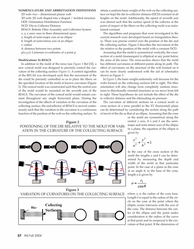
Modifications To RFACSIn addition to the mold of the torso (see Figure 2 Ref [3]), a
new conical mold was designed to precisely control the cur-vature of the collecting surface (Figure 1). A control algorithmof the RFCAS was developed such that the movement of thedie could be precisely controlled so as to place the fibers onthe specified location of the mold at known curvature (Figure2). The conical mold was constructed such that the central axisof the mold would be mounted on the seventh axis of theRFACS. The curvature of the conical mold would remain con-stant throughout any single horizontal plane. During theinvestigation of the effects of variation in the curvature of thecollecting surface, the end-effector of RFACS is moved contin-uously such that the variation in the curvature is a continuousfunction of the position of the web on the collecting surface. To
obtain a uniform basis weight of the web on the collecting sur-face we kept the die-to-collector distance (DCD) constant at allheights on the mold. Additionally, the speed of seventh axiswas altered such that the surface speed of the collector at thepoint of impact of the fibers on the collecting mold was main-tained constant.
The algorithms and programs that were investigated in thecurrent research were developed based on triangulation theo-ry. There was precise control over the position of the die andthe collecting surface. Figure 2 describes the movement of thedie relative to the position of the mold with a constant DCD.
Assuming that the mold is symmetrical vertically, the cross-section of a mold (mannequin) is elliptical at any point belowthe arms of the torso. The cross-section shows that the moldhas different curvatures at different points along its path. Theeffect of curvatures on the structure of the web formed on itcan be more clearly understood with the aid of schematicsshown in Figure 3.
In Figure 3, the basis weight uniformity will decrease for thewebs formed on the collecting surfaces left to right. The fiberorientation will also change from completely random struc-tures to directionally oriented structures as we move from leftto right. These hypotheses do not include the effect of the dieto collector distance and the attenuating air pressure.
The curvature of different sections on a conical mold orcross section of a torso parallel to the XY (horizontal) planecan be determined by considering the section along the pathof travel of the die as that of an ellipse. Assuming that the cone
or the mold are symmetrical along thecentral z axis, if a and b are the semi-major and semi-minor axes of the ellipsein a plane, the equation of the ellipse isgiven by
In the case of the cross section of themold the lengths a and b can be deter-mined by measuring the depth andwidth of the mold at that particularpoint. In the case of a plane in the coneat an angle θ, to the base of the cone,length a is given by
where r2 is the radius of the cone base.Length b is equal to the radius of the cir-cle on the cone at the point where theelliptic center intersects with the axis ofthe cone. The distance between the cen-ter of the ellipse and the point underconsideration is the radius of the curveat that point and its reciprocal is the cur-vature at that point. If the dimensions of
37 INJ Fall 2004
Figure 2POSITIONING OF THE DIE RELATIVE TO THE MOLD FOR VARI-
ATION IN THE CURVATURE OF THE COLLECTING SURFACE.
Figure 3VARIATION OF CURVATURES ON THE COLLECTING SURFACE

the cone or the mold cannot be determined by regular mea-surement, the coordinates of the center and the point under atwhich the curvature has to be considered can be determinedby triangulation, explained in detail in the succeeding sec-tions.
Analytical Mesurement Of CurvatureAssuming that there is axial symmetry on the mold, along
the z–axis in the xz-plane, a curve in 3D space can be analyzedas a curve in a 2D plane. Analytically, the curvature can bedetermined if the co-ordinates of three points on the curve, in2D space, are known. In the case of a curve in 3D space the co-ordinates of four points are required. The distance betweentwo points in 3D space is known to abide by the followingrelationship:
The distance between the center of the circle and a point onthe curve is the radius of the curve and is a constant for an arcthat is a part of the circle.
For a given set of four co-ordinates (p1-p4), which lie on thearc of a curve in 3D space, the equation and hence the curva-ture of the arc passing through those four co-ordinates can bedetermined. If p1 = (x1, y1, z1), p2 = (x2, y2, z2), p3 = (x3, y3, z3), p4
= (x4, y4, z4) are the four coordinates on the same curve, thecenter pc = (xc, yc, zc), of this curve can be determined by solv-ing the distance equations of the four coordinates with thecenter of the curve.
The simultaneous equations that are formed are:
Solution of these simultaneous equations yields the uniqueco-ordinates (xc, yc, zc) of the center of the arc and hence theradius and curvature of this arc can be determined. The coor-dinates of the different points on the mold can be determinedwith reference to a universal coordinate system using theposition of the end effector of RFAC system as discussed byFarer et al [3].
Materials and MethodsPolypropylene (PP) meltblown samples were produced
using PP resin with a nominal melt-flow-rate (MFR) of 1200(IV = 0.8), on the Robotic Fiber Assembly and Control Systems(RFACS). Fabrics for evaluation were formed directly onto theconical mold described earlier. The die (which is 7.62 cm widewith total of 90 holes in a single row) attached to the end effec-tor of the robot made one to and fro motion to form the webstructure on the conical mold. The meltblowing equipmentspecifications used are previously reported [4].
The process parameters that were used to produce the fab-rics are given below.
Take-up Speed (surface speed of the mold): 6.09 m/min Die-to-Collector-Distance (DCD): 15.24 cmPolymer Throughput Rate: 3.7 x10⁻²g/min/holeAttenuating Air Pressure: 1.4 barFiber Stream Approach Angle (see definition on Figure 1 of
reference [4]): 90O
Curvature of the Collecting Surface: 10 m-1, 7.69 m-1, 6.58 m-1,5.43 m-1, 4.97 m-1, 4.66 m-1, 4.07 m-1, 3.50 m-1, 2.85 m-1, and 1.95m-1
All of the image analysis work that is reported in thisresearch was conducted using image analysis software devel-oped by Nonwovens Cooperative Research Center [7]. Theorientation distribution of the webs formed determined onthe images of the web captured at a magnification of unity.This gives the global ODF of the fibers in the web, rather thanthe local orientation that will be obtained at higher magnifi-cation. The image that is thus captured is then analyzed usingFast Fourier Transform to determine the distribution of fibersin various orientation angles as described elsewhere [10]. Theanisotropy parameter gives a one-dimensional interpretationof the ODF from the frequency distribution of the ODF. Theequations and description of determining the anisotropyparameter has been discussed by Kim et al [7].
The diameter of the fibers was measured on SEM images ofthe webs obtained at 500X. The SEM images were obtainedon a Hitachi ESEM S3200 in the environmental mode.Multiple samples of the images were obtained and eachimage of the web contained at least 20 fibers. The diameterswere measured using the manual measurement option in the
image analysis software. The manual scale in thesoftware was calibrated using the scale on theSEM image. A straight line across the image wasdrawn randomly and the diameters of all fibers,which intersected the straight line, were mea-sured. Values obtained from multiple images of
the same web were combined and grouped in two-microme-ter ranges.
The test sample used to determine the pore size wasabout 5 cm in diameter, but the effective size of the samplethat was subjected to the airflow was 1.25 cm in diameter.The sample was saturated with Porewick‚, a fluorocarbonsolution with a surface tension of 16 dynes/cm. The satu-rated sample was loaded into the test chamber and subject-ed to an increasing airflow through the sample (detaileddescription in reference 12). As the airflow was increasedthrough the sample the solution was expelled from thepores. The samples were initially tested to determine themaximum air pressure needed to expel all the solution fromthe pores. The maximum pressure needed was determinedto be less than 0.7 bar and hence the maximum on the sys-tem was set to 0.7 bar. The pore size measurements wereperformed on five different samples that were randomly cutfrom each fiberweb produced.
38 INJ Fall 2004

Results and DiscussionsThe ODF and the anisotropy parameter of the webs formed
at different curvatures on the mold are given in Figure 4 andFigure 5 respectively. For a given rotational speed of the collec-tor, as the curvature of the collecting surface decreases, the sur-face speed of the collecting surface increases. This, in an idealcondition, would lead to the preferential orientation of thefibers in the direction of the tangential direction of the rotatingsurface. To overcome the issue of change in surface speedalong the curvature of the collecting surface, the RFACS wasprogrammed such that the relative surface speed of the moldwould be close to constant. At constant surface speed the basisweight of the web does not vary significantly (Table 1).
Hence, the variation in the fiber arrangement is significant-ly due to the curvature of the collecting surface. As the curva-ture increases some of the fibers will travel a longer distanceto reach the collecting surface (Figure 3). The fibers at highcurvatures travel along the longer path parallel to the tangentof the curve. The attenuating force on the fiber at this point isthe drag and elongation forces exerted on them as they travelalong a path parallel to the tangent on the collector surface [8,14]. As the path for travel is longer when the curvatureincreases (Figure 3), the fiber experiences the drag force for alonger duration leading to the formation of finer fibers. These
fibers will be further forced to orient themselves in the direc-tion of the velocity vector at the point on the curve. This leads
to more fibers orienting in the directionof rotation of the curve leading togreater anisotropy in the web as thecurvature increases. The curvature ofthe collecting surface for the web has asignificant influence on the frequencydistribution of the fibers in the web. Athigh curvatures the anisotropy para-meter of the web develops a plateau(Figure 5). It indicates that within theexperimental range, further increase inthe curvature will not increase the pref-erential orientation of the fibers in themachine direction of the web. A statisti-cal analysis of the data indicates thatthe ODF of the web is also influencedby the orientation angle under consid-eration (F-value of 485.81 at Pr. > F = 0).It implies that there is an interactionbetween the orientation angle and thecurvature of the collecting surface onthe % frequency of fibers in a particularorientation.
The average pore size and the averagefiber diameter of the web are given inFigure 6. As the curvature of the collect-ing surface increases, the average poresize of the web decreases and the fiberdiameter decreases. A decrease in thefiber diameter decreases the pore sizeof the web [7, 12]. An increase in thecurvature increases the orientation of
39 INJ Fall 2004
Table 1BASIS WEIGHT OF WEBS PRODUCED AT
DIFFERENT CURVATURES (AVERAGE AND STANDARD ERROR FROM 5
SAMPLES OF 5.08 CM X 10.16 CM)
Figure 4ODF FOR WEBS COLLECTED AT DIFFERENT CURVATURES
(THROUGHPUT: 3.7 X 10⁻² G/MIN/HOLE, ATTENUATING AIRPRESSURE: 1.4 BAR, TAKE-UP SPEED: 6.09 M/MIN; APPROACH
ANGLE: 90 DEGREE)

the fibers in the machine direction (along the velocity vector)of the collecting surface. As more fibers are parallelized, thefiber cover increases due to less fiber overlapping. Thisreduces the effective pore diameter. The cumulative frequen-cy (Figure 7) of the distribution of pore sizes has a wider range
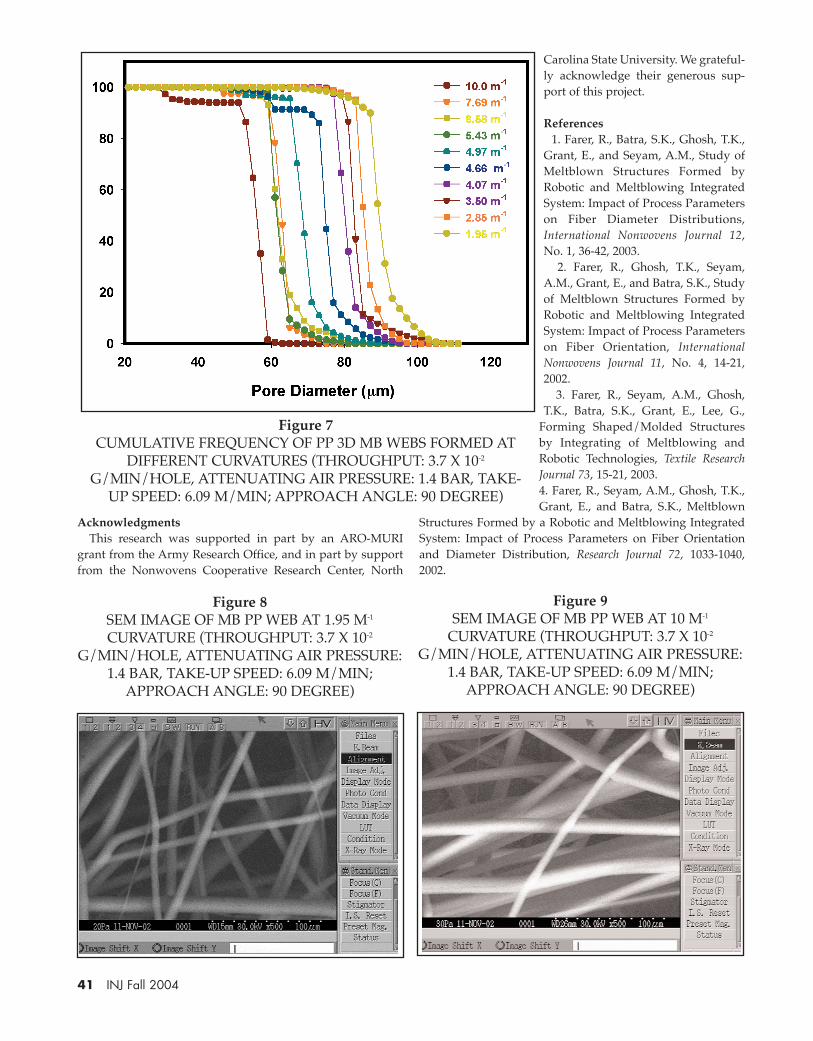
at low curvatures, (more random fiber arrange-ment) while at high curvatures the distributionrange is narrower. SEM images of the webs pro-duced at 1.95 m-1 and 10 m-1 curvature are shown inFigures 8 and 9. It is obvious from the images thatwebs produced at higher curvatures have smallerpore size. The Chi-square test conducted on thepore and fiber diameter distributions are summa-rized in Table 2. The analyses imply that the porediameter distributions and fiber diameter distribu-tions for the various webs tested are significantlydifferent from each other, and that the fiber diame-ter and pore diameter are significantly affected bythe curvature of the collecting surface.
ConclusionsAn increase in the curvature of the collecting sur-face affects the fiber alignment in the web signifi-cantly. An increase in the curvature causes thefibers in the web to be more oriented in themachine direction due to increase in the force act-ing on the fibers at the point of contact. Further, anincrease in the curvature leads to the formation offiner fibers. The increase in the drag force on thefibers causes the attenuation of the fibers. A largerpercentage of the fibers in the web have smallerdiameters as the curvature of the collecting surfaceincreases. As the curvature increases, the formationof finer pores in the web is the combined effect offiner fibers that are highly oriented in the machinedirection. The distribution of the pores in the webgets broader as the curvature of the collecting sur-face decreases.An understanding of the effects of the curvature ofthe collecting surface on the structure of the webcan be utilized to design the structure of the web tomeet the requirements of specific end uses. Thebasis weight uniformity of the web on the 3D struc-ture can be controlled by maintaining a uniform
surface speed on the collecting surface. The structure of theweb thus formed can be altered by changing the variousprocess parameters to produce the specific web structure sodesired.
40 INJ Fall 2004
Figure 5ANISOTROPY PARAMETER FOR WEBS COLLECTED AT
DIFFERENT CURVATURES (THROUGHPUT: 3.7 X 10⁻²
G/MIN/HOLE, ATTENUATING AIR PRESSURE: 1.4 BAR,TAKE-UP SPEED: 6.09 M/MIN; APPROACH ANGLE: 90DEGREE, WITH STANDARD ERROR OF 5 SAMPLES)
Table 2CHI-SQUARE AND ITS PROBABILITY
FOR THE FIBER AND PORE DIAMETER DISTRIBUTIONS OF WEBS
FORMED AT DIFFERENT CURVATURES
Figure 6AVERAGE PORE DIAMETER AND FIBER DIAMETER OF
WEBS OBTAINED AT DIFFERENT CURVATURES(THROUGHPUT: 3.7 X 10⁻² G/MIN/HOLE,
ATTENUATING AIR PRESSURE: 1.4 BAR, TAKE-UPSPEED: 6.09 M/MIN; APPROACH ANGLE: 90 DEGREE,
WITH STANDARD ERROR OF 5 SAMPLES)
AcknowledgmentsThis research was supported in part by an ARO-MURI
grant from the Army Research Office, and in part by supportfrom the Nonwovens Cooperative Research Center, North
Carolina State University. We grateful-ly acknowledge their generous sup-port of this project.
References1. Farer, R., Batra, S.K., Ghosh, T.K.,
Grant, E., and Seyam, A.M., Study ofMeltblown Structures Formed byRobotic and Meltblowing IntegratedSystem: Impact of Process Parameterson Fiber Diameter Distributions,International Nonwovens Journal 12,No. 1, 36-42, 2003.
2. Farer, R., Ghosh, T.K., Seyam,A.M., Grant, E., and Batra, S.K., Studyof Meltblown Structures Formed byRobotic and Meltblowing IntegratedSystem: Impact of Process Parameterson Fiber Orientation, InternationalNonwovens Journal 11, No. 4, 14-21,2002.
3. Farer, R., Seyam, A.M., Ghosh,T.K., Batra, S.K., Grant, E., Lee, G.,
Forming Shaped/Molded Structuresby Integrating of Meltblowing andRobotic Technologies, Textile ResearchJournal 73, 15-21, 2003.4. Farer, R., Seyam, A.M., Ghosh, T.K.,Grant, E., and Batra, S.K., Meltblown
Structures Formed by a Robotic and Meltblowing IntegratedSystem: Impact of Process Parameters on Fiber Orientationand Diameter Distribution, Research Journal 72, 1033-1040,2002.
41 INJ Fall 2004
Figure 7CUMULATIVE FREQUENCY OF PP 3D MB WEBS FORMED AT
DIFFERENT CURVATURES (THROUGHPUT: 3.7 X 10⁻²
G/MIN/HOLE, ATTENUATING AIR PRESSURE: 1.4 BAR, TAKE-UP SPEED: 6.09 M/MIN; APPROACH ANGLE: 90 DEGREE)
Figure 8SEM IMAGE OF MB PP WEB AT 1.95 M-1
CURVATURE (THROUGHPUT: 3.7 X 10⁻²
G/MIN/HOLE, ATTENUATING AIR PRESSURE:1.4 BAR, TAKE-UP SPEED: 6.09 M/MIN;
APPROACH ANGLE: 90 DEGREE)
Figure 9SEM IMAGE OF MB PP WEB AT 10 M-1
CURVATURE (THROUGHPUT: 3.7 X 10⁻²
G/MIN/HOLE, ATTENUATING AIR PRESSURE:1.4 BAR, TAKE-UP SPEED: 6.09 M/MIN;
APPROACH ANGLE: 90 DEGREE)

5. Griesbach, H, L., R. D. Pike; S. W. Gwaltney; R. L. Levy;L. H. Sawyer; R. M. Shane; P. A. Sasse; “Method for makingshaped nonwoven fabric”, U. S. Patent 5,575894, 1996.
6. Griesbach, H, L., R. D. Pike; S. W. Gwaltney; R. L. Levy;L. H. Sawyer; R. M. Shane; P. A. Sasse; “Shaped nonwovenfabric”, U. S. Patent 5643653, 1997.
7. Kim, H. S. and B. Pourdeyhimi., “A note on the effect offiber diameter, fiber crimp and fiber orientation on pore sizein thin webs”, International Nonwovens Journal 9, No. 4, 15-19,2000.
8. Malkan, S. R. and L. C. Wadsworth, “Polymer LaidSystems – Nonwovens: Theory, Process, Performance andTesting”, TAPPI Press, Atlanta, GA, 171-192, 1993.
9. Miura. Y., and J. Hosoka, “Electrochemical Process in theMolding of Nonwoven Structures”, Textile Research Journal 49,685-690, 1979.
10. Pourdeyhimi, B, Davis, H., and Dent, R., MeasuringFiber Orientation in Nonwovens Part III: Fourier Transform,Textile Research Journal 67, 143 - 151, 1997.
11. Shambaugh, R. L., A Macroscopic View of theMeltblowing Process for Producing Microfibers, NonwovenTechnology Today, Miller Freeman Publication, San Francisco,CA, 41-54, 1989.
12. Velu, Y. K., Ghosh, T. K., and Seyam, A. M., MeltblownStructures formed by a robotic and meltblowing integratedsystem: Impact of process parameters on the Pore Size., TextileResearch Journal 73, 971-979, 2003.
13. Velu, Y. K., Farer, R. R., Ghosh. T.K., and Seyam, A. M.,Formation of Shaped/ Molded Meltblowing NonwovenStructures, Journal of Textile and Apparel, Technology andManagement, 1 No 1, 2000 (http://www.tx.ncsu.edu/jtatm)
14. Yin, H., Z. Yan, and R. R. Bressee, “Experimental Studyof the Meltblowing Process”, International Nonwovens Journal8, No. 1, 130-139, 1999. — INJ
42 INJ Fall 2004