Megan’s Treadmill Final Design Report
117
Team Megan’s Treadmill | Final Design Report Megan’s Treadmill Final Design Report M.E. Senior Project Fall 2016-Spring 2017 Sponsor Michael Lara Special Olympics, San Luis Obispo County [email protected] Advisor Sarah Harding Professor, Mechanical Engineering Department [email protected] Team Daniel Byrne Michael Peck Eddie Ruano [email protected] Team Megan’s Treadmill
Transcript of Megan’s Treadmill Final Design Report

Team Megan’s Treadmill | Final Design Report
Megan’s Treadmill
Final Design Report
M.E. Senior Project Fall 2016-Spring 2017
Sponsor
Michael Lara
Special Olympics, San Luis Obispo County
Advisor
Sarah Harding
Professor, Mechanical Engineering Department
Team
Daniel Byrne
Michael Peck
Eddie Ruano
Team Megan’s Treadmill

Team Megan’s Treadmill | Final Design Report
STATEMENT OF DISCLAIMER
This project is the result of a class assignment; thus, it has been graded and accepted as fulfillment of the
course requirements. Acceptance does not imply technical accuracy or reliability. Any use of information
in this report is done at the risk of the user. These risks may include catastrophic failure of the device or
infringement of patent or copyright laws. California Polytechnic State University, San Luis Obispo and
its staff cannot be held liable for any use or misuse of this project.

Team Megan’s Treadmill | Final Design Report
Table of Contents Chapter Title Page
Title Page i
Statement of Disclaimer ii
Table of Contents iii
List of Figures iv
List of Tables vi
Executive Summary vii
1 Introduction 1
2 Background 1
[2.1] Benefits of Physical Activity Benefits of routine exercise for the visually impaired 1
[2.2] Donation of Treadmills Details on the donation of Desmo Model Treadmill 1
[2.3] Market Comparison Research and comparison to commercially available solutions 2
[2.4] Handheld Controllers Preliminary research on handheld controllers 4
[2.5] Extra Features Research on other features available 5
3 Objectives 5
[3.1] Customer Requirements The range of requirements desired from the sponsor/customer 5
[3.2] Quality Function Deployment The method used to develop and rate specifications 6
[3.3] Discussion of Specifications List of engineering specifications tailored to project 7
4 Design Development 8
[4.1] Concept Generation Methods and results from ideation 8
[4.2] Idea Selection Decision process for narrowing down ideas 12
[4.3] Technical Content Overview of top design 17
5 Detailed Design Phase 21
[5.1] Controller Assembly Description of grips and control functions 22
[5.2] Railing System Description of side and sliding rails 25
[5.3] Tactile Positioning System Description of the material placed on the treads 29
[5.4] Electronics Systems Description of DESI and electronic components 30
6 Manufacturing and Assembly 39
[6.1] Mechanical Systems Details of the railing and controller assemblies 39
[6.2] Electrical Systems Details of the code, electronic components, and wiring 43
7 Safety Considerations 48
8 Testing 49
9 Cost Analysis 52
10 Maintenance and Repair Considerations 53
11 Management Plan 54
12 Conclusion 55
13 Works Cited 56
14 Appendices 57

Team Megan’s Treadmill | Final Design Report
List of Figures
Figure 1: Woodway Desmo model treadmill ........................................................................................... 02
Figure 2: Cybex 625T Total Access treadmill ......................................................................................... 03
Figure 3: LiteGait Gatekeeper GK2200T treadmill ................................................................................. 03
Figure 4: LiteGait harness ........................................................................................................................ 03
Figure 5: LiteGait handheld remote ......................................................................................................... 04
Figure 6: Flipper universal remote ........................................................................................................... 04
Figure 7: Sony PlayStation 4 controller ................................................................................................... 04
Figure 8: Critical specifications and their respective functions ............................................................... 08
Figure 9: Prototyped baton....................................................................................................................... 10
Figure 10: Sketch of two-handed controller ............................................................................................ 10
Figure 11: Added material on treadmill for sensory feedback ................................................................ 11
Figure 12: Sketch of trackpad feedback system ...................................................................................... 11
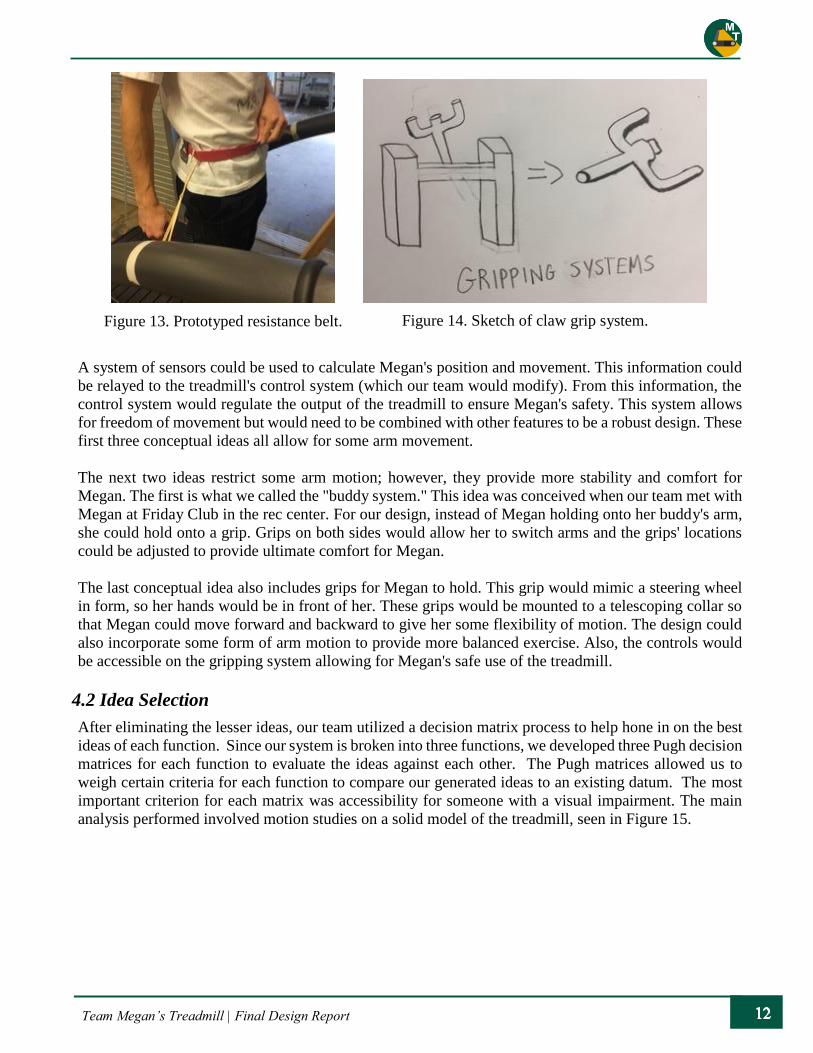
Figure 13: Prototyped resistance belt ....................................................................................................... 12
Figure 14: Sketch of claw grip system ..................................................................................................... 12
Figure 15: SolidWorks model of treadmill used for reference ................................................................ 13
Figure 16: SolidWorks model of preliminary design system .................................................................. 18
Figure 17: Frame diagram of Woodway Desmo treadmill ...................................................................... 19
Figure 18: Upper rail diagram of Woodway ............................................................................................ 20
Figure 19: ESI Corp main interface unit .................................................................................................. 20
Figure 20: ESI Corp brushless servo motor control unit ......................................................................... 20
Figure 21: Raspberry Pi 3 Model B ......................................................................................................... 21
Figure 22: Solid model of the treadmill for the detailed design .............................................................. 22
Figure 23: Controller assembly ................................................................................................................ 23
Figure 24: Alternate gripping system ...................................................................................................... 24
Figure 25: Two-button input and rotary switch ....................................................................................... 25
Figure 26: Railing system assembly ........................................................................................................ 25
Figure 27: T-Slots loading cases .............................................................................................................. 27
Figure 28: Cross section of T-Slot ........................................................................................................... 28
Figure 29: Sliding rail configuration........................................................................................................ 28
Figure 30: Silicone bumpers positioning ................................................................................................. 30
Figure 31: Simplified model of existing electrical system ...................................................................... 31
Figure 32: Breakdown of interface board: methods of entry ................................................................... 32
Figure 33: Location of various sensors on the railing assembly .............................................................. 33
Figure 34: DESI modes of operation ....................................................................................................... 35
Figure 35: Subsystem relationships after DESI insertion ........................................................................ 35
Figure 36: DESI voice commands data flow ........................................................................................... 37
Figure 37: Raspberry PiCam and ribbon attachment cable ..................................................................... 38
Figure 38: Caster foot vs. base foot for rail mounting ............................................................................. 39
Figure 39: Barebones railing system........................................................................................................ 40
Figure 40: Mounting for handlebars ........................................................................................................ 40
Figure 41: Sliding rail assembly .............................................................................................................. 41
Figure 42: Proximity sensor mounting case............................................................................................. 41
Figure 43: Conductive Tape..................................................................................................................... 41
Figure 44: Implemented control panel inputs .......................................................................................... 42
Figure 45: Tactile Feedback bumpers glued to treads ............................................................................. 42

Team Megan’s Treadmill | Final Design Report
Figure 46: Detailed design 3-D model from CDR and FDR ................................................................... 43
Figure 47: Oscilloscope capture of speed up command .......................................................................... 44
Figure 48: Unknown periodic control signal sent to main interface module ........................................... 44
Figure 49: Molex connection on the front of the Woodway display board ............................................. 43
Figure 50: Checking the readings from the Woodway treadmill to replicate commands ....................... 43
Figure 51: The electronic control input flow ........................................................................................... 43
Team Megan’s Treadmill | Final Design Report
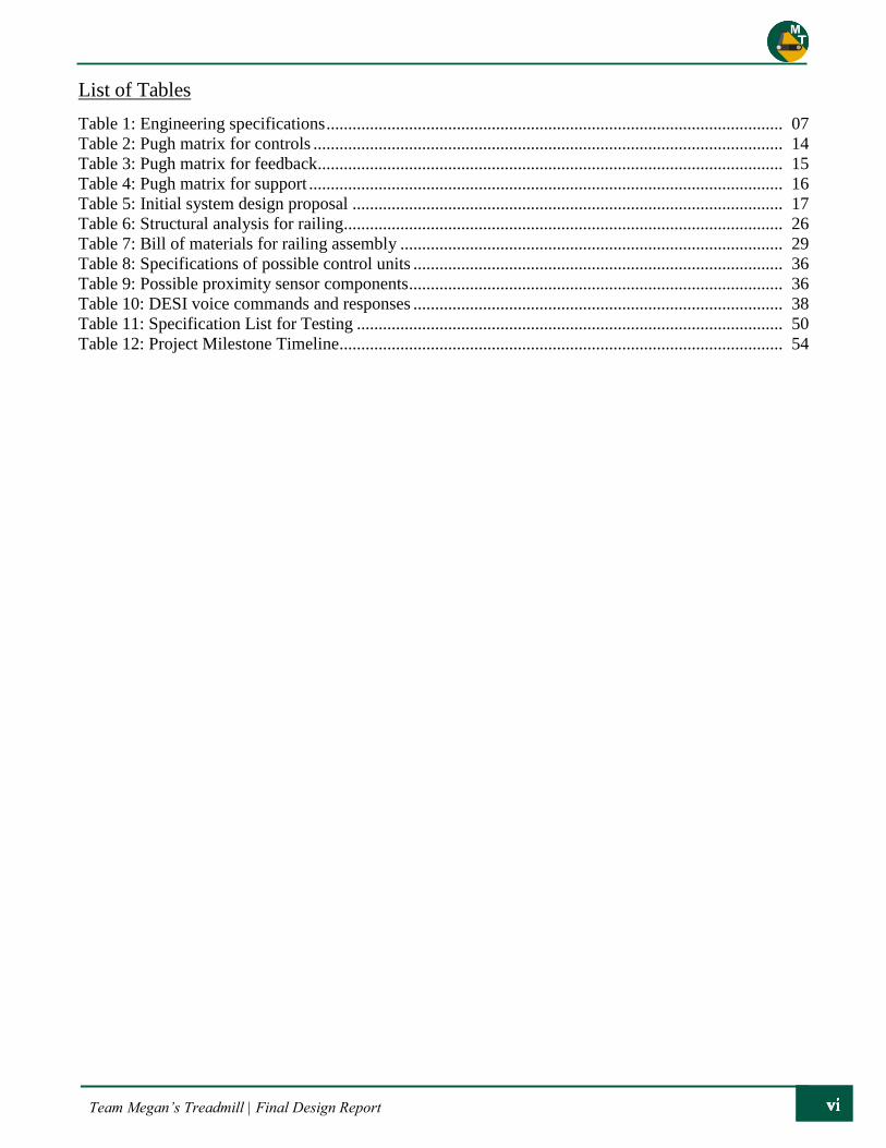
List of Tables
Table 1: Engineering specifications ......................................................................................................... 07
Table 2: Pugh matrix for controls ............................................................................................................ 14
Table 3: Pugh matrix for feedback........................................................................................................... 15
Table 4: Pugh matrix for support ............................................................................................................. 16
Table 5: Initial system design proposal ................................................................................................... 17
Table 6: Structural analysis for railing ..................................................................................................... 26
Table 7: Bill of materials for railing assembly ........................................................................................ 29
Table 8: Specifications of possible control units ..................................................................................... 36
Table 9: Possible proximity sensor components ...................................................................................... 36
Table 10: DESI voice commands and responses ..................................................................................... 38
Table 11: Specification List for Testing .................................................................................................. 50
Table 12: Project Milestone Timeline ...................................................................................................... 54

Team Megan’s Treadmill | Final Design Report
Executive Summary
This project, known as “Megan’s Treadmill,” was brought to the California Polytechnic State University
(Cal Poly) mechanical engineering senior project class for the 2016 – 2017 school year by Michael Lara.
Michael, the sports manager for San Luis Obispo County Special Olympics, has been sponsoring senior
projects at Cal Poly for nine years. This project revolves around Megan, a 21-year-old Special Olympian
in the local San Luis Obispo area who loves to move. Due to a visual impairment, Megan is limited in
the amount of time she can be active, as she relies on the help of a partner when she exercises. The goal
of this project was to adapt a standard treadmill to provide a safe and accessible environment for Megan
to exercise independently.
During our team’s design development phase, we identified three functions that our design had to
incorporate to fully solve the problem: controls, feedback, and support. All the components of our final
design contribute to one of these function categories.
The new control system was designed to be simple, intuitive, and accessible to Megan. To organize all
the possible functions, controls were separated into primary and secondary groups. Primary controls
consist of the commands essential to operation, including turning the treadmill on and off, pausing, and
changing speeds. These commands are given through physical inputs located on the control panel, as they
provide quick response and tactile feedback. There are two buttons (on/off and pause) and a rotary switch
(speed levels). Secondary controls include the nonessential commands that add to the workout
experience. The Amazon Alexa system was integrated to allow Megan to use voice commands to receive
various data readouts (speed, distance travel, time of workout) and control music.
The feedback systems provide information about the operation of the treadmill and Megan’s status. Our
team implemented tactile feedback to help Megan stay centered on the treads and auditory feedback to
inform her of the treadmill’s status. There is also a sensor grid providing information of Megan’s status
to the control unit. With this information, the control unit can implement the correct protocols for the
given situation.
The support system allows Megan to physically interact with the treadmill safely. The railing system is
bolted to a plywood base to provide strength and stability. The side rails extend along the entire treadmill
to provide support for Megan during operation and as she gets on and off the treadmill. There are also
multiple gripping surfaces for Megan to hold while exercising to ensure comfort and safety.
To address the mechanical and electrical aspects associated with this project, multiple engineering
disciplines were necessary. To this end, our team consisted of two mechanical engineers and one
computer engineer. The different knowledge bases of our team assisted in producing a versatile and
robust design. The mechanical and electrical components of our design were integrated to function
cooperatively as an independent system. The final product contains both this new system and the original
Woodway treadmill, creating a brand-new workout experience.
Team Megan’s Treadmill | Final Design Report
1. Introduction
Megan is a 21-year-old Special Olympian in the local San Luis Obispo area who loves to move. Due to
a visual impairment, Megan is limited in the amount of time she can be active, as she relies on the help
of a partner when she exercises. For example, during the school year, Megan participates in the Friday
Club in the local recreation center where she teams up with a kinesiology student to obtain physical
activity. She also competes every year in the Special Olympics held at Cuesta College. Megan races in
the 50- and 100-meter dash holding a baton attached to a rope as a guide. Her other source of training is
on a treadmill; however, she is dependent on a guide to help her walk safely. While she enjoys this,
Megan would like to be able to exercise safely without relying on assistance.
Michael Lara, the sports manager for San Luis Obispo County Special Olympics, has been sponsoring
senior projects at California Polytechnic State University (Cal Poly) for nine years. Mr. Lara wanted to
help Megan increase her physical activity and find more independence, so he brought this project, known
as “Megan’s Treadmill,” to the mechanical engineering senior project class. The goal of this project was
to adapt a treadmill to provide a safe and accessible environment for Megan to exercise independently.
Our team consisted of three senior engineering students attending Cal Poly: Daniel Byrne (ME), Michael
Peck (ME), and Eddie Ruano (CPE). The different knowledge bases of our team assisted in producing a
versatile and robust design. This final design report documents the full design process for this project,
from start to finish. In this report, our team will highlight the many steps we took to produce our final
detailed design, as well as the process of turning this design into a fully functional product.
2. Background
2.1 Benefits of Physical Activity
Routine physical activity promotes a healthy mental state with reduced stress and balanced mood.
Individuals with disabilities who get consistent physical activity tend to have an improved quality of life,
balance, and muscle strength1. The recommended amount of weekly physical activity is two hours;
however, achieving this goal can prove difficult for various reasons. An individual with a disability might
find themselves in need of direct supervision because of poor accessibility or concerns of safety, but this
should not be a deterrent for anyone wishing to improve their quality of life. As such, Special Olympics
advocates a philosophy and mission to help those with intellectual disabilities discover new abilities,
skills, and strengths through awareness and opportunity.
2.2 Donation of Treadmills
Michael Lara and Special Olympics managed to secure a donation of two Desmo Model treadmills from
Cal Poly’s recreation center for this project. This donation aided in keeping the overall cost of the project
low and provided a base structure from which our team could add to and adapt to shape our final product.
Being industrial-grade treadmills, they are reliable in their design; however, they lack the accessibility
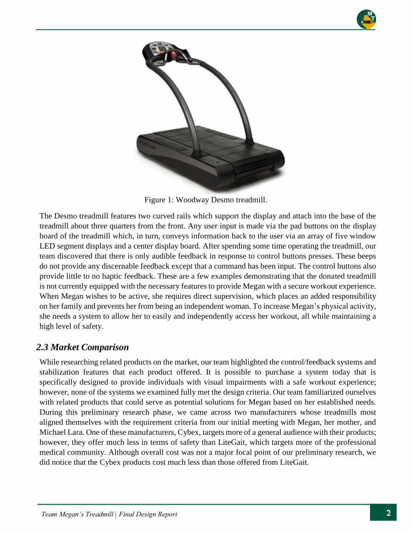
and safety features needed to accommodate Megan. The Woodway Desmo Model treadmill with the
upgraded Personal Trainer Display is shown in Figure 1, and its specifications and other information can
be found in Appendix A. Further details on the operation of the treadmill are available in section 4.3
Technical Content.
Team Megan’s Treadmill | Final Design Report
The Desmo treadmill features two curved rails which support the display and attach into the base of the
treadmill about three quarters from the front. Any user input is made via the pad buttons on the display
board of the treadmill which, in turn, conveys information back to the user via an array of five window
LED segment displays and a center display board. After spending some time operating the treadmill, our
team discovered that there is only audible feedback in response to control buttons presses. These beeps
do not provide any discernable feedback except that a command has been input. The control buttons also
provide little to no haptic feedback. These are a few examples demonstrating that the donated treadmill
is not currently equipped with the necessary features to provide Megan with a secure workout experience.
When Megan wishes to be active, she requires direct supervision, which places an added responsibility
on her family and prevents her from being an independent woman. To increase Megan’s physical activity,
she needs a system to allow her to easily and independently access her workout, all while maintaining a
high level of safety.
2.3 Market Comparison
While researching related products on the market, our team highlighted the control/feedback systems and
stabilization features that each product offered. It is possible to purchase a system today that is
specifically designed to provide individuals with visual impairments with a safe workout experience;
however, none of the systems we examined fully met the design criteria. Our team familiarized ourselves
with related products that could serve as potential solutions for Megan based on her established needs.
During this preliminary research phase, we came across two manufacturers whose treadmills most
aligned themselves with the requirement criteria from our initial meeting with Megan, her mother, and
Michael Lara. One of these manufacturers, Cybex, targets more of a general audience with their products;
however, they offer much less in terms of safety than LiteGait, which targets more of the professional
medical community. Although overall cost was not a major focal point of our preliminary research, we
did notice that the Cybex products cost much less than those offered from LiteGait.
Figure 1: Woodway Desmo treadmill.
Team Megan’s Treadmill | Final Design Report
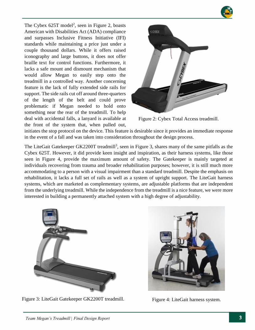
The Cybex 625T model2, seen in Figure 2, boasts
American with Disabilities Act (ADA) compliance
and surpasses Inclusive Fitness Initiative (IFI)
standards while maintaining a price just under a
couple thousand dollars. While it offers raised
iconography and large buttons, it does not offer
braille text for control functions. Furthermore, it
lacks a safe mount and dismount mechanism that
would allow Megan to easily step onto the
treadmill in a controlled way. Another concerning
feature is the lack of fully extended side rails for
support. The side rails cut off around three-quarters
of the length of the belt and could prove
problematic if Megan needed to hold onto
something near the rear of the treadmill. To help
deal with accidental falls, a lanyard is available at
the front of the system that, when pulled out,
initiates the stop protocol on the device. This feature is desirable since it provides an immediate response
in the event of a fall and was taken into consideration throughout the design process.
The LiteGait Gatekeeper GK2200T treadmill3, seen in Figure 3, shares many of the same pitfalls as the
Cybex 625T. However, it did provide keen insight and inspiration, as their harness systems, like those
seen in Figure 4, provide the maximum amount of safety. The Gatekeeper is mainly targeted at
individuals recovering from trauma and broader rehabilitation purposes; however, it is still much more
accommodating to a person with a visual impairment than a standard treadmill. Despite the emphasis on
rehabilitation, it lacks a full set of rails as well as a system of upright support. The LiteGait harness
systems, which are marketed as complementary systems, are adjustable platforms that are independent
from the underlying treadmill. While the independence from the treadmill is a nice feature, we were more
interested in building a permanently attached system with a high degree of adjustability.
Figure 2: Cybex Total Access treadmill.
Figure 3: LiteGait Gatekeeper GK2200T treadmill. Figure 4: LiteGait harness system.
Team Megan’s Treadmill | Final Design Report
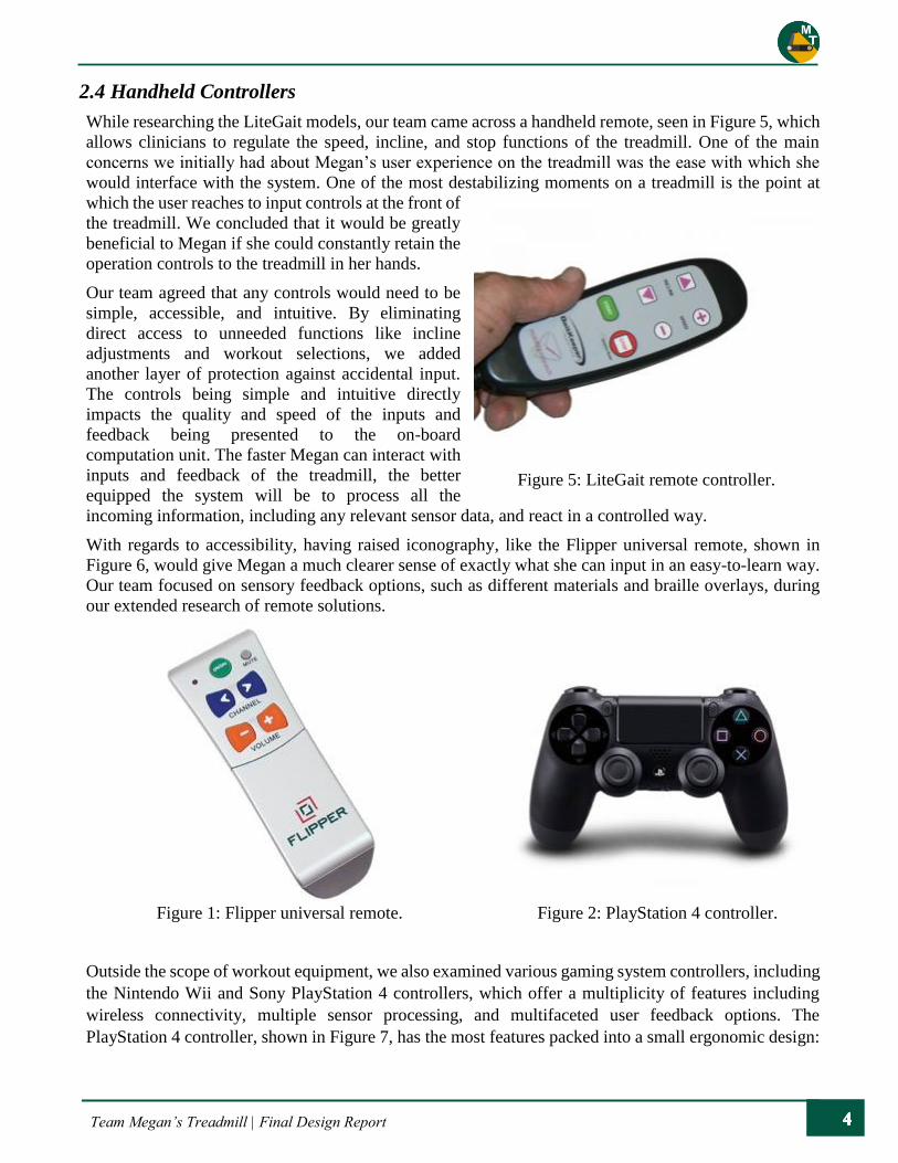
2.4 Handheld Controllers
While researching the LiteGait models, our team came across a handheld remote, seen in Figure 5, which
allows clinicians to regulate the speed, incline, and stop functions of the treadmill. One of the main
concerns we initially had about Megan’s user experience on the treadmill was the ease with which she
would interface with the system. One of the most destabilizing moments on a treadmill is the point at
which the user reaches to input controls at the front of
the treadmill. We concluded that it would be greatly
beneficial to Megan if she could constantly retain the
operation controls to the treadmill in her hands.
Our team agreed that any controls would need to be
simple, accessible, and intuitive. By eliminating
direct access to unneeded functions like incline
adjustments and workout selections, we added
another layer of protection against accidental input.
The controls being simple and intuitive directly
impacts the quality and speed of the inputs and
feedback being presented to the on-board
computation unit. The faster Megan can interact with
inputs and feedback of the treadmill, the better
equipped the system will be to process all the
incoming information, including any relevant sensor data, and react in a controlled way.
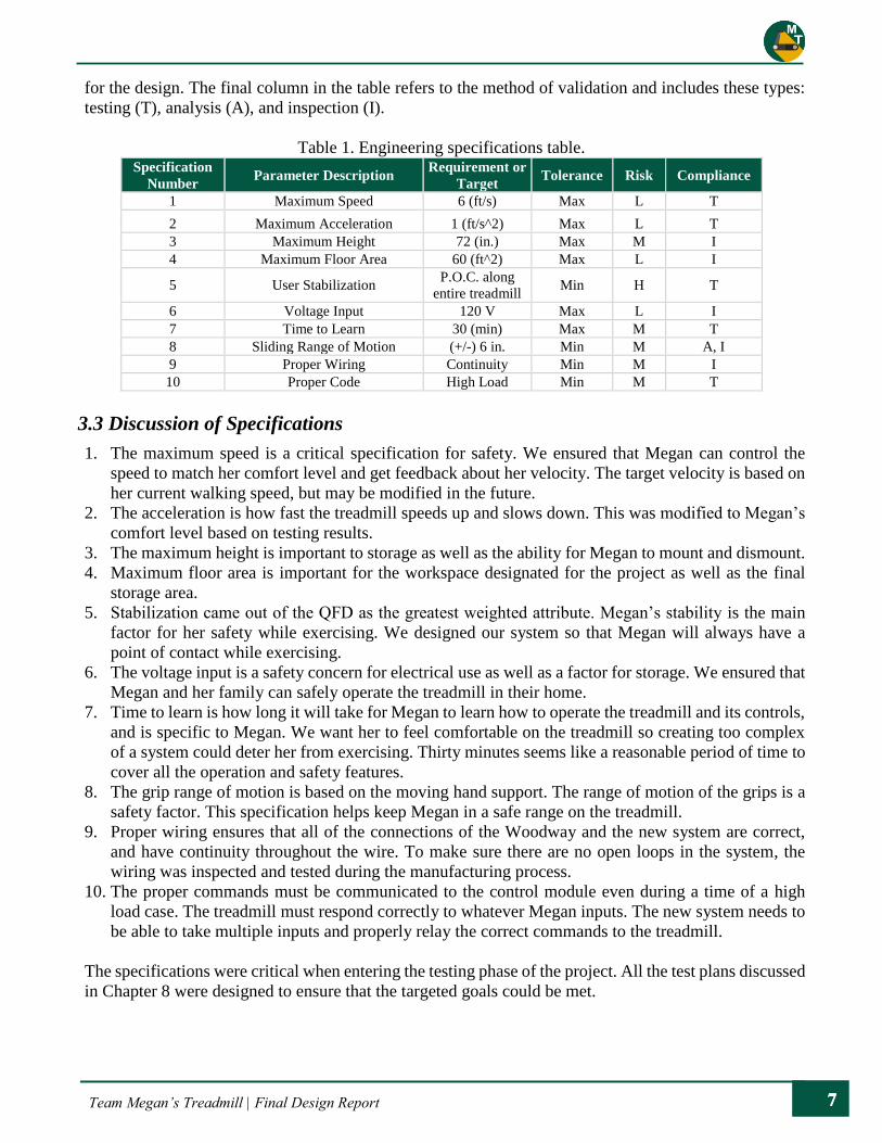
With regards to accessibility, having raised iconography, like the Flipper universal remote, shown in
Figure 6, would give Megan a much clearer sense of exactly what she can input in an easy-to-learn way.
Our team focused on sensory feedback options, such as different materials and braille overlays, during
our extended research of remote solutions.
Outside the scope of workout equipment, we also examined various gaming system controllers, including
the Nintendo Wii and Sony PlayStation 4 controllers, which offer a multiplicity of features including
wireless connectivity, multiple sensor processing, and multifaceted user feedback options. The
PlayStation 4 controller, shown in Figure 7, has the most features packed into a small ergonomic design:
Figure 5: LiteGait remote controller.
Figure 1: Flipper universal remote. Figure 2: PlayStation 4 controller.

Team Megan’s Treadmill | Final Design Report
programmable vibration patterns, onboard speaker for direct audible feedback, and Bluetooth
connectivity for wireless handling.
Another example of a product that has been adapted for people with visual impairments is the system
implemented at some crosswalks. Many cross walks now use vibration and a high-pitch beeping noise to
notify pedestrians that it is safe to cross the road4. Some streets even have a voice stating which street is
safe to cross at the intersection. These modes of feedback are extremely useful to someone with a visual
impairment because they do not have to rely on the typical visual traffic signals to safely arrive at their
destination.
The Desmo treadmill currently has controls for incline functions, different programmed workouts, and
other features that do not necessarily correlate with Megan’s needs. While we do not want to remove
these functionalities and features, we want to restrict the ability to inadvertently trigger these during
Megan’s use of the treadmill.
2.5 Extra Features
In addition to the remote, the sensor data provided on the LiteGait also piqued our interest because it
allowed the clinician to view and track the following user information: speed, cadence, stride and step
time, stride and step length, and so on. Although the Gatekeeper treadmill only used this data for logging
and clinician analysis, it could also be processed in real time. Processing proximity data would allow the
treadmill to offer a checks and balances approach to Megan’s input and offer yet another layer of error
protection.
The possibility of alerts and notifications for Megan’s family was discussed with Michael Lara and
Megan’s mother. We researched real time video streaming options and found that the implementation of
such a system would be reliant on the connectivity of the treadmill. Lightweight systems like the
Raspberry Pi would allow this type of communication to be implemented using built-in tools.
More details on the feasibility of these features which fall outside the main scope of the project, including
Braille Note connectivity, are discussed in greater detail in Chapter 4. Not all of the features discussed in
this section were included in the final product.
3. Objectives
Megan loves to walk and be active, and she wants to be able to use a treadmill on her own. The primary
goal of this project is to provide a safe and accessible environment for Megan to exercise on a treadmill.
This is a satisfactory goal, but to create the best design that truly solves the problem, we needed to
discover what was necessary for a successful product. To do this, our team met with Megan, her mother,
Sonya, and Michael Lara. We then came up with a list of customer requirements that our design should
encompass. All the requirements are designed to ensure Megan’s safety and give her independence while
exercising. In this section, we will summarize this list of requirements, how we developed them into
specifications that can be measured, and how they affected the designed solution.
3.1 Customer Requirements
After our first formal meeting and interview with Megan, her mother, and Michael, our team identified
the following as the customer’s requirements:
● Limit the maximum speed of the treadmill.
● Implement a procedure to stop the moving belt under special circumstances.

Team Megan’s Treadmill | Final Design Report
● Ensure there is an accessible and safe way for Megan to get on and off the treadmill.
● Implement protection in the event Megan does fall.
● Incorporate input controls that are accessible to individuals with a visual impairment.
● Incorporate a system that gives feedback which allows Megan to understand what the treadmill is
doing.
● The design should allow Megan to independently operate and adjust settings, etc.
● There should be little or no restriction on Megan’s movement to provide a pleasant and natural
experience.
● The design of Megan’s grip location should be comfortable and natural.
● Incorporate a way to log statistics such as elapsed time, total miles walked, etc. and make them
available to Megan and her family.
● The design should include a means of upper body exercise for Megan while walking on the
treadmill.
● The adaptations to the treadmill should be relatively small so the treadmill can be stored/used in a
space such as a bedroom.
● The adaptations to the treadmill should not affect the ability to transport the treadmill.
● The design should be versatile or adaptable so that the restrictions on maximum speed, etc. can
scale to match Megan’s fitness and capabilities.
Our team used these customer requirements to develop engineering specifications which can be measured
and tested to ensure the design meets the needs listed above. This was accomplished using a process
called Quality Function Deployment (QFD) which will be explained next.
3.2 Quality Function Deployment
Our team used a quality function deployment diagram to transform our customer requirements into
engineering specifications. Our team’s QFD diagram can be seen in Appendix B. The diagram ensures
that every requirement is accounted for in the specifications and that every specification is necessary to
fulfill the customer needs. A relative weight was calculated for each specification based on the
conjunction of two factors. First, we assigned a number (1-5 in our case) to each requirement which
represents the initial weight/importance of the requirement. Second, these weights were modified based
on the dependency or relationship between the requirements and each specification. So, the more an
engineering specification fulfills the customer requirements, the higher relative weight or importance of
the specification.
From the QFD diagram, we found that the specifications with the greatest importance are Megan’s
stabilization, some safety features such as the maximum allowable speed, and Megan’s ability to operate
the treadmill independently. These factors guided our work throughout the design phase. Quality
Function Deployment also allows current products or solutions to be measured against the needs and
specifications that have been identified. From this analysis, we concluded that the accessible treadmills
and LiteGait harness systems provide many great features but ultimately fail to provide a safe
environment that encourages autonomous use for Megan. The goal of our design was to incorporate the
good features of these alternatives and correct the shortcomings.
From our QFD diagram, our team created a specification table (Table 1). This table lists each
specification, their maximum or minimum allowable value, their assessed risk, and how we ensured the
final product complies with these specifications. The risk refers to the risk that each specification could
not be met in the final design. The options for risk are low (L), medium (M), or high (H). Megan’s
stabilization, or her ability to walk comfortably and smoothly, is the highest risk and our biggest concern
Team Megan’s Treadmill | Final Design Report
for the design. The final column in the table refers to the method of validation and includes these types:
testing (T), analysis (A), and inspection (I).
Table 1. Engineering specifications table. Specification
Number Parameter Description
Requirement or
Target Tolerance Risk Compliance
1 Maximum Speed 6 (ft/s) Max L T
2 Maximum Acceleration 1 (ft/s^2) Max L T
3 Maximum Height 72 (in.) Max M I
4 Maximum Floor Area 60 (ft^2) Max L I
5 User Stabilization P.O.C. along
entire treadmill Min H T
6 Voltage Input 120 V Max L I
7 Time to Learn 30 (min) Max M T
8 Sliding Range of Motion (+/-) 6 in. Min M A, I
9 Proper Wiring Continuity Min M I
10 Proper Code High Load Min M T
3.3 Discussion of Specifications
1. The maximum speed is a critical specification for safety. We ensured that Megan can control the
speed to match her comfort level and get feedback about her velocity. The target velocity is based on
her current walking speed, but may be modified in the future.
2. The acceleration is how fast the treadmill speeds up and slows down. This was modified to Megan’s
comfort level based on testing results.
3. The maximum height is important to storage as well as the ability for Megan to mount and dismount.
4. Maximum floor area is important for the workspace designated for the project as well as the final
storage area.
5. Stabilization came out of the QFD as the greatest weighted attribute. Megan’s stability is the main
factor for her safety while exercising. We designed our system so that Megan will always have a
point of contact while exercising.
6. The voltage input is a safety concern for electrical use as well as a factor for storage. We ensured that
Megan and her family can safely operate the treadmill in their home.
7. Time to learn is how long it will take for Megan to learn how to operate the treadmill and its controls,
and is specific to Megan. We want her to feel comfortable on the treadmill so creating too complex
of a system could deter her from exercising. Thirty minutes seems like a reasonable period of time to
cover all the operation and safety features.
8. The grip range of motion is based on the moving hand support. The range of motion of the grips is a
safety factor. This specification helps keep Megan in a safe range on the treadmill.
9. Proper wiring ensures that all of the connections of the Woodway and the new system are correct,
and have continuity throughout the wire. To make sure there are no open loops in the system, the
wiring was inspected and tested during the manufacturing process.
10. The proper commands must be communicated to the control module even during a time of a high
load case. The treadmill must respond correctly to whatever Megan inputs. The new system needs to
be able to take multiple inputs and properly relay the correct commands to the treadmill.
The specifications were critical when entering the testing phase of the project. All the test plans discussed
in Chapter 8 were designed to ensure that the targeted goals could be met.
Team Megan’s Treadmill | Final Design Report
4. Design Development
To understand our final product, this report includes all the stages of our design process. Because of this,
many aspects from our preliminary and detailed designs (Chapters 4 and 5) were altered, added to, or
eliminated in the final product for feasibility or improved quality. The information of this chapter will
provide insight into our team’s thought process and the progression of design aspects throughout
development of the project.
This project was unique in that we had a singular customer, Megan. This means that any decisions that
were made needed to keep her needs as the priority. To start off the project we wanted to get to know
Megan’s personality and her walking style. Due to Megan’s participation in Cal Poly’s Friday Club, we
had a simple line of communication. Our team recorded video of Megan on the treadmill to gain a better
understanding of her walking/running pattern. This helped us conduct some physical testing and analysis
needed throughout the manufacturing and testing process. Another distinctive part of this project was the
modification of a Woodway treadmill. The overall design was built upon the existing platform. Because
the treadmills were already donated, we conducted initial testing on the treadmill to help with the design
process. Our team continued to work with Megan and the treadmill as we moved through each phase of
the project.
Based on the background research and specifications outlined in our QFD, the overall design of this
project focuses on two main criteria: safety and independence. Based on these criteria, our team
determined the most important specifications to develop related functions, as seen in Figure 8.
Figure 8. Critical specifications and their respective functions.
The three subsystems that we identified were controls, feedback, and support. Each of these systems
assist Megan in safely interacting with the treadmill while promoting an independent workout
environment. Our team focused on these three categories as we generated ideas for our conceptual design.
4.1 Concept Generation
To identify the best design, our team used a variety of ideation methods to generate ideas to solve the
problem. During this idea generation stage, no ideas were excluded, regardless of their feasibility. This
lack of judgement allowed our team to be creative and find a wide variety of solutions, which positively
impacted our final conceptual design.
The first ideation methods our team used were brain-sketching and brainstorming. Brain-sketching calls
for each team member to draw an aspect of the design. After five minutes, we passed our drawings to
another teammate, who made additions to the original drawing. This method provided the opportunity

Team Megan’s Treadmill | Final Design Report
for one idea to spark another and develop into something new. Next, we completed a brainstorming
session in which we wrote all ideas that came to mind on sticky notes. This provided a free-flowing
environment which allowed our minds to wander to different parts of the design. These methods
prevented any judgement being passed on the ideas because they were done individually and in silence.
Our team was then able to look back at the large variety of ideas we generated and start to categorize
them.
After the initial ideation sessions, we started to focus on categories of ideas for the different functions
that our product would have to perform. Our team created classifications such as control methods,
feedback from the treadmill, systems to prevent falling, and modes for mounting and dismounting the
treadmill. We took all our ideas and sorted them into these categories to help us compare them. This
method also allowed our team to employ a different ideation approach by concentrating on individual
focused parts of the design.
Once our team had generated as many ideas as possible for each category, we began to narrow them
down by eliminating those that were not feasible. We then created a morphological table with the
remaining ideas listed in their categories. By choosing one idea from each category, our team "built"
different, complete systems that could serve as our design. Lastly, our team created physical prototypes
to help evaluate some of our preliminary concepts. The results of this process will be discussed more in
the following chapter.
As mentioned previously, our team split up our design into three functions that would deliver a successful
product for Megan. The following sections highlight some of the conceptual ideas that were produced
for each of these functions.
Control Ideas
The first controller concept was a remote-control system, like one used for a television or the remote used
in the LiteGait system. The inspiration for this idea came from Megan's participation in the Special
Olympics where she holds a baton as a guide while she runs. This remote controller could be a substitute
for the baton as it provides familiarity and a way for Megan to control the treadmill. This remote would
serve as an accessible controller for someone with a visual impairment by using a mixture of geometries,
texture and braille. A prototyped version of this can be seen in Figure 9.
The remote controller idea was bridged to another idea, where the controller would be part of a mounted
system which Megan could hold onto. This system could be implemented as a one- or two-handed system.
The one-handed approach would allow Megan to always have free motion of one arm, while the two-
handed system would provide the possibility of having more controls or a more intuitive and simple
design. Sketches of the controller-mounted ideas can be seen in Figure 10.

Team Megan’s Treadmill | Final Design Report
Figure 9. Prototyped baton. Figure 10. Sketch of two-handed controller.
Another idea our team generated was the use of elliptical poles, adding aspects of an elliptical machine
to the treadmill. These poles would provide support for Megan to hold onto without needing an actual
control system as the machine would be self-powered. This is a simpler interface that limits the output of
the treadmill to match Megan's output, thus keeping her safe. This idea was very appealing because it
added another layer of exercise for Megan.
Our team's last main idea for the controls system was a system of "smart sensors." These sensors would
be located on grips and along the treadmill and would receive data on how Megan was moving. This
could provide the treadmill with a kinematic and kinetic profile of Megan, and the data would be sent to
a control system. This system would ideally change the treadmill's output to adapt to Megan's immediate
needs.
Feedback Ideas
The first two ideas for feedback systems were audible; one providing a voice, which gives the status of
the treadmill, and the other using sound effects to signal what the treadmill is doing. The voice feedback
would state important statistics, such as the speed of the treadmill or time spent exercising, or whether
the treadmill was speeding up or slowing down. The signaling by sound effects would work in a similar
way by using different noises, tones, or intensities to distinguish exactly what the treadmill was doing.
Vibration would provide direct physical feedback to Megan to indicate the treadmill's motion. This would
operate similarly to the noise feedback, as the vibrations would differ based on the changes of the
treadmill. For instance, the vibration could lose intensity over time to match the treadmill's decreasing
speed, thus, providing intuitive feedback to Megan.
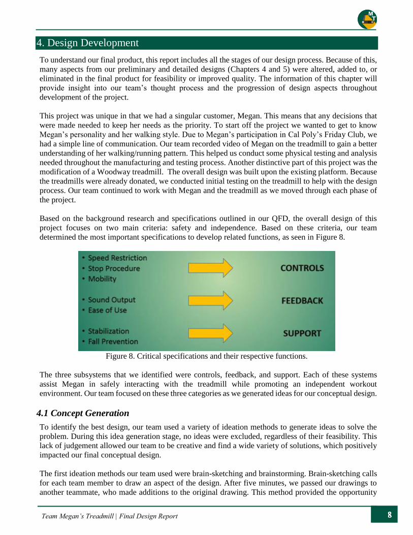
The treads of the treadmill could also be modified to provide feedback. Our team's idea was to add
material on the outer sides of the treads. If Megan were to step on this material, she would know she was
walking near the outside edges of the treadmill, and she would be able to correct her position by moving
back to the center. The amount of material, its positioning, and its properties (such as firmness) could be
optimized so it was comfortable to walk on, while providing obvious feedback of Megan's location. This
method was prototyped, with string and foam, and proved to be very informative, as seen in Figure 11.
Team Megan’s Treadmill | Final Design Report
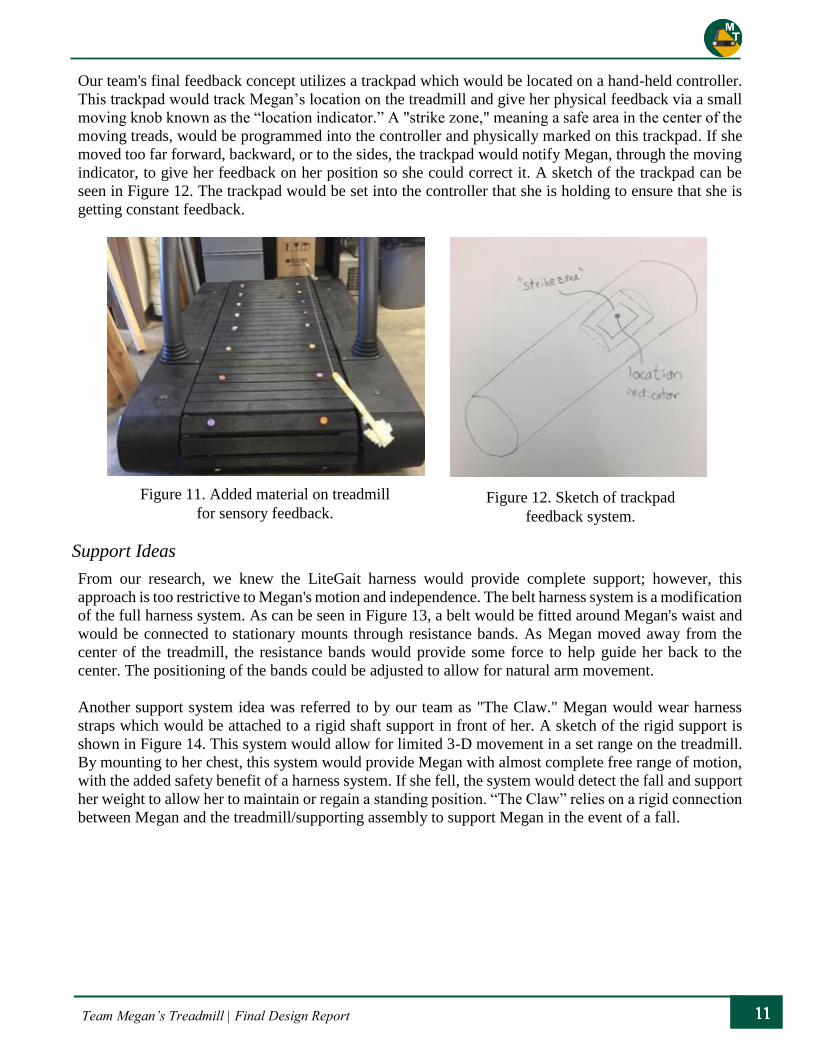
Our team's final feedback concept utilizes a trackpad which would be located on a hand-held controller.
This trackpad would track Megan’s location on the treadmill and give her physical feedback via a small
moving knob known as the “location indicator.” A "strike zone," meaning a safe area in the center of the
moving treads, would be programmed into the controller and physically marked on this trackpad. If she
moved too far forward, backward, or to the sides, the trackpad would notify Megan, through the moving
indicator, to give her feedback on her position so she could correct it. A sketch of the trackpad can be
seen in Figure 12. The trackpad would be set into the controller that she is holding to ensure that she is
getting constant feedback.
Support Ideas
From our research, we knew the LiteGait harness would provide complete support; however, this
approach is too restrictive to Megan's motion and independence. The belt harness system is a modification
of the full harness system. As can be seen in Figure 13, a belt would be fitted around Megan's waist and
would be connected to stationary mounts through resistance bands. As Megan moved away from the
center of the treadmill, the resistance bands would provide some force to help guide her back to the
center. The positioning of the bands could be adjusted to allow for natural arm movement.
Another support system idea was referred to by our team as "The Claw." Megan would wear harness
straps which would be attached to a rigid shaft support in front of her. A sketch of the rigid support is
shown in Figure 14. This system would allow for limited 3-D movement in a set range on the treadmill.
By mounting to her chest, this system would provide Megan with almost complete free range of motion,
with the added safety benefit of a harness system. If she fell, the system would detect the fall and support
her weight to allow her to maintain or regain a standing position. “The Claw” relies on a rigid connection
between Megan and the treadmill/supporting assembly to support Megan in the event of a fall.
Figure 11. Added material on treadmill
for sensory feedback. Figure 12. Sketch of trackpad
feedback system.
Team Megan’s Treadmill | Final Design Report
A system of sensors could be used to calculate Megan's position and movement. This information could
be relayed to the treadmill's control system (which our team would modify). From this information, the
control system would regulate the output of the treadmill to ensure Megan's safety. This system allows
for freedom of movement but would need to be combined with other features to be a robust design. These
first three conceptual ideas all allow for some arm movement.
The next two ideas restrict some arm motion; however, they provide more stability and comfort for
Megan. The first is what we called the "buddy system." This idea was conceived when our team met with
Megan at Friday Club in the rec center. For our design, instead of Megan holding onto her buddy's arm,
she could hold onto a grip. Grips on both sides would allow her to switch arms and the grips' locations
could be adjusted to provide ultimate comfort for Megan.
The last conceptual idea also includes grips for Megan to hold. This grip would mimic a steering wheel
in form, so her hands would be in front of her. These grips would be mounted to a telescoping collar so
that Megan could move forward and backward to give her some flexibility of motion. The design could
also incorporate some form of arm motion to provide more balanced exercise. Also, the controls would
be accessible on the gripping system allowing for Megan's safe use of the treadmill.
4.2 Idea Selection
After eliminating the lesser ideas, our team utilized a decision matrix process to help hone in on the best
ideas of each function. Since our system is broken into three functions, we developed three Pugh decision
matrices for each function to evaluate the ideas against each other. The Pugh matrices allowed us to
weigh certain criteria for each function to compare our generated ideas to an existing datum. The most
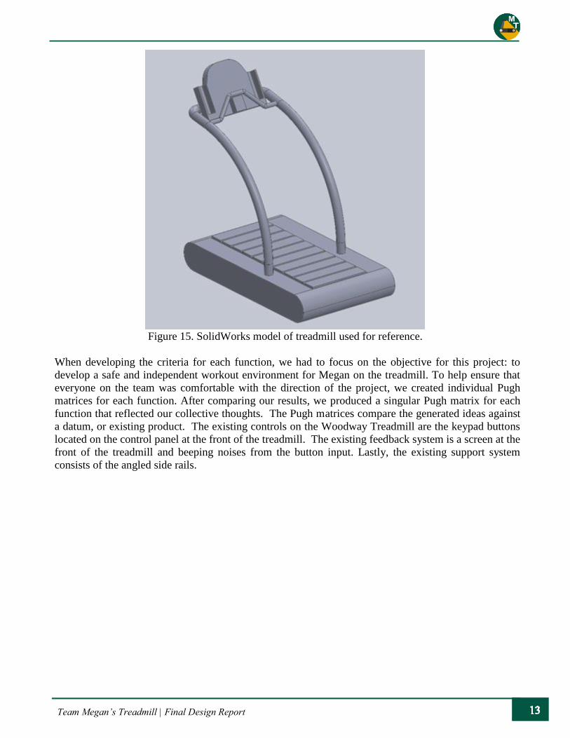
important criterion for each matrix was accessibility for someone with a visual impairment. The main
analysis performed involved motion studies on a solid model of the treadmill, seen in Figure 15.
Figure 13. Prototyped resistance belt. Figure 14. Sketch of claw grip system.
Team Megan’s Treadmill | Final Design Report
Figure 15. SolidWorks model of treadmill used for reference.
When developing the criteria for each function, we had to focus on the objective for this project: to
develop a safe and independent workout environment for Megan on the treadmill. To help ensure that
everyone on the team was comfortable with the direction of the project, we created individual Pugh
matrices for each function. After comparing our results, we produced a singular Pugh matrix for each
function that reflected our collective thoughts. The Pugh matrices compare the generated ideas against
a datum, or existing product. The existing controls on the Woodway Treadmill are the keypad buttons
located on the control panel at the front of the treadmill. The existing feedback system is a screen at the
front of the treadmill and beeping noises from the button input. Lastly, the existing support system
consists of the angled side rails.

Team Megan’s Treadmill | Final Design Report
Controls Selection
Table 2 overviews the Pugh decision matrix for the controls system, which compared the baton, two-
handed mounted controls, one-handed mounted controls, smart sensors, and elliptical poles to a datum
of keypad buttons. The primary, secondary, and redundant system are marked in the matrix to designate
the order of the ranking. The highest weighted design considerations were the accessibility of the controls
for someone with a visual impairment, ergonomics, and simplicity to design/incorporate. While all of the
alternatives came in close rating, the highest rated designs were the baton and two-handed system, with
smart sensors coming in close behind. The highest ratings for these were driven by their associated
feedback methods, as well as their ergonomics. The lowest rated design was the elliptical pole setup due
to the need to reconfigure the treadmill to be self-powered. Both the baton and two-handed mounted
controller system provide great ease of use since the controls are so accessible. Our final design
implemented the more cautious, mounted controller as it provides support and some freedom of motion.
Table 2. Pugh matrix for controls system.
Controls Pugh Matrix
Solution Alternatives
Key Criteria Import
ance
Rat
ing
Key
pad
Butt
ons
Bat
on
Tw
o H
ands
One
Han
d
Sm
art
Contr
ols
Ell
ipti
cal
Pole
s
Accessible to a visual impairment 5 + + + + +
Automatic Feedback 2 S + S + +
Number of Control Surfaces 1 + + S - -
Simplicity to Incorporate 3 S S + - -
Time to Learn 1 + S + + S
Ergonomics 4 S + S S S
Non-Restrictive 3 + - - + -
Sum of Positives 4 4 3 4 2
Sum of Negatives 0 1 1 2 3
Sum of Sames 3 2 3 1 2
Weighted Sum of Positives 10 12 9 11 7
Weighted Sum of Negatives 0 3 3 4 7
TOTALS 10 9 6 7 0
Primary System
Secondary System
Redundant System
Team Megan’s Treadmill | Final Design Report
Feedback Selection
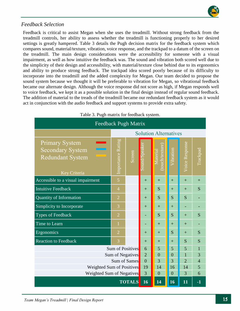
Feedback is critical to assist Megan when she uses the treadmill. Without strong feedback from the
treadmill controls, her ability to assess whether the treadmill is functioning properly to her desired
settings is greatly hampered. Table 3 details the Pugh decision matrix for the feedback system which
compares sound, material/texture, vibration, voice response, and the trackpad to a datum of the screen on
the treadmill. The main design considerations were the accessibility for someone with a visual
impairment, as well as how intuitive the feedback was. The sound and vibration both scored well due to
the simplicity of their design and accessibility, with material/texture close behind due to its ergonomics
and ability to produce strong feedback. The trackpad idea scored poorly because of its difficulty to
incorporate into the treadmill and the added complexity for Megan. Our team decided to propose the
sound system because we thought it will be preferable to vibration for Megan, so vibrational feedback
became our alternate design. Although the voice response did not score as high, if Megan responds well
to voice feedback, we kept it as a possible solution in the final design instead of regular sound feedback.
The addition of material to the treads of the treadmill became our redundant feedback system as it would
act in conjunction with the audio feedback and support systems to provide extra safety.
Table 3. Pugh matrix for feedback system.
Feedback Pugh Matrix
Solution Alternatives
Key Criteria Import
ance
Rat
ing
Scr
een
Sound/S
pea
ker
Mat
eria
l
(touch
/tex
ture
)
Vib
rati
on
Voic
e R
esponse
Tra
ckp
ad
Accessible to a visual impairment 5 + + + + +
Intuitive Feedback 4 + S + + S
Quantity of Information 2 + S S S -
Simplicity to Incorporate 3 + + + - -
Types of Feedback 2 - S S + S
Time to Learn 1 - + + + -
Ergonomics 2 + + S + S
Reaction to Feedback 3 + + + S S
Sum of Positives 6 5 5 5 1
Sum of Negatives 2 0 0 1 3
Sum of Sames 0 3 3 2 4
Weighted Sum of Positives 19 14 16 14 5
Weighted Sum of Negatives 3 0 0 3 6
TOTALS 16 14 16 11 -1
Primary System
Secondary System
Redundant System
Team Megan’s Treadmill | Final Design Report
Support Selection
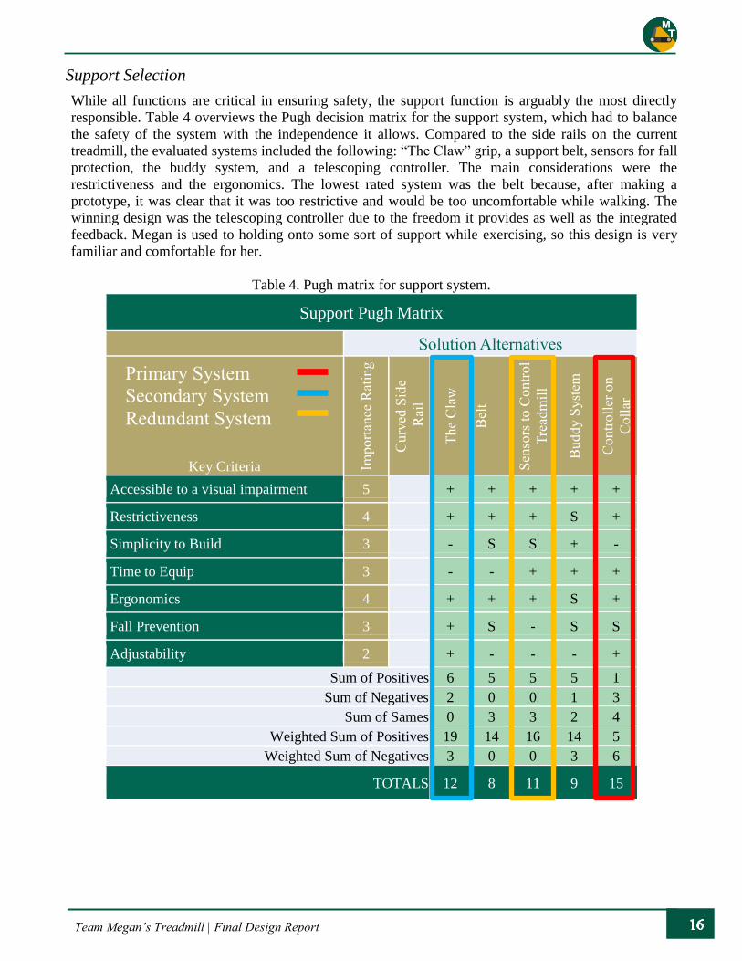
While all functions are critical in ensuring safety, the support function is arguably the most directly
responsible. Table 4 overviews the Pugh decision matrix for the support system, which had to balance
the safety of the system with the independence it allows. Compared to the side rails on the current
treadmill, the evaluated systems included the following: “The Claw” grip, a support belt, sensors for fall
protection, the buddy system, and a telescoping controller. The main considerations were the
restrictiveness and the ergonomics. The lowest rated system was the belt because, after making a
prototype, it was clear that it was too restrictive and would be too uncomfortable while walking. The
winning design was the telescoping controller due to the freedom it provides as well as the integrated
feedback. Megan is used to holding onto some sort of support while exercising, so this design is very
familiar and comfortable for her.
Table 4. Pugh matrix for support system.
Support Pugh Matrix
Solution Alternatives
Key Criteria Import
ance
Rat
ing
Curv
ed S
ide
Rai
l
The
Cla
w
Bel
t
Sen
sors
to C
ontr
ol
Tre
adm
ill
Buddy S
yst
em
Contr
oll
er o
n
Coll
ar
Accessible to a visual impairment 5 + + + + +
Restrictiveness 4 + + + S +
Simplicity to Build 3 - S S + -
Time to Equip 3 - - + + +
Ergonomics 4 + + + S +
Fall Prevention 3 + S - S S
Adjustability 2 + - - - +
Sum of Positives 6 5 5 5 1
Sum of Negatives 2 0 0 1 3
Sum of Sames 0 3 3 2 4
Weighted Sum of Positives 19 14 16 14 5
Weighted Sum of Negatives 3 0 0 3 6
TOTALS 12 8 11 9 15
Primary System
Secondary System
Redundant System
Team Megan’s Treadmill | Final Design Report
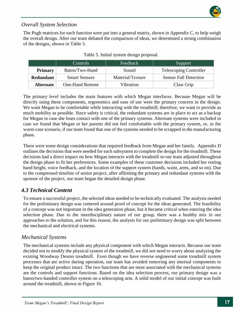
Overall System Selection
The Pugh matrices for each function were put into a general matrix, shown in Appendix C, to help weigh
the overall design. After our team debated the comparison of ideas, we determined a strong combination
of the designs, shown in Table 5.
Table 5. Initial system design proposal.
Controls Feedback Support
Primary Baton/Two-Hand Sound Telescoping Controller
Redundant Smart Sensors Material/Texture Sensor Fall Detection
Alternate One-Hand Remote Vibration Claw Grip
The primary level includes the main features with which Megan interfaces. Because Megan will be
directly using these components, ergonomics and ease of use were the primary concern in the design.
We want Megan to be comfortable while interacting with the treadmill; therefore, we want to provide as
much mobility as possible. Since safety is critical, the redundant systems are in place to act as a backup
for Megan in case she loses contact with one of the primary systems. Alternate systems were included in
case we found that Megan or her parents did not feel comfortable with the primary system, or, in the
worst-case scenario, if our team found that one of the systems needed to be scrapped in the manufacturing
phase.
There were some design considerations that required feedback from Megan and her family. Appendix D
outlines the decisions that were needed for each subsystem to complete the design for the treadmill. These
decisions had a direct impact on how Megan interacts with the treadmill so our team adjusted throughout
the design phase to fit her preferences. Some examples of these customer decisions included her resting
hand height, voice feedback, and the location of the support system (hands, waist, arms, and so on). Due
to the compressed timeline of senior project, after affirming the primary and redundant systems with the
sponsor of the project, our team began the detailed design phase.
4.3 Technical Content
To ensure a successful project, the selected ideas needed to be technically evaluated. The analysis needed
for the preliminary design was centered around proof of concept for the ideas generated. The feasibility
of a concept was not important in the idea generation phase, but it became critical when entering the idea
selection phase. Due to the interdisciplinary nature of our group, there was a healthy mix in our
approaches to the solution, and for this reason, the analysis for our preliminary design was split between
the mechanical and electrical systems.
Mechanical Systems
The mechanical systems include any physical component with which Megan interacts. Because our team
decided not to modify the physical system of the treadmill, we did not need to worry about analyzing the
existing Woodway Desmo treadmill. Even though we have reverse engineered some treadmill system
processes that are active during operation, our team has avoided removing any internal components to
keep the original product intact. The two functions that are most associated with the mechanical systems
are the controls and support functions. Based on the idea selection process, our primary design was a
baton/two-handed controller system on a telescoping arm. A solid model of our initial concept was built
around the treadmill, shown in Figure 16.

Team Megan’s Treadmill | Final Design Report
Figure 16. SolidWorks model of preliminary design system.
Figure 16 shows the various systems that were included in the preliminary design to help Megan while
on the treadmill. In this design, the added side rails are positioned on the inside of the existing side bars,
along the track, and are at waist height for Megan to hold while exercising. Like most rail systems, the
side rails were specified to be made mostly of metal. They wouldn’t need to carry an extremely large
load, but there could be little to no deflection if Megan put her full weight on the rails. The side rails
would also need to be able to support the controller and any other additional features. While the side rails
are important in helping Megan move along the treadmill, the primary support system is the telescoping
controller. This controller is designed to have linear motion along the treadmill, preventing Megan from
swaying to the side while on the treadmill. To ensure that Megan is in a safe area on the treadmill, the
telescoping arm design has a limited range of motion. If Megan is walking slower than the treadmill’s
speed, she will begin to drift toward the back of the treadmill. Once the arm extends to its maximum
allowable range, a slowing command engages to help Megan return to the centered location on the
treadmill. While Megan will be getting feedback from the controller and sound system, this design calls
for some form of material feedback be mounted to the bottom bar of the side rails. There are different
materials, such as a brush or foam, that could be implemented to keep Megan in line on the treadmill.
Material could also be added onto the treads with either an adhesive or pin.
In this preliminary design, the side rails are mounted to the ground to provide a stable base for support.
Using standard tubing, the side railing could be cut and joined to create a support system specifically
designed for Megan. The telescoping arm should have a resistance to motion away from the designated
"safe zone" on the treadmill. A spring could be used to pull the telescoping arm back to a neutral state.
Also, the treadmill would be alerted by a sensor mounted to the telescoping arm if Megan goes too far
back on the treadmill, and a protocol would be triggered to help correct this.
Since safety is a key concern in this project, possible safety hazards are outlined in a safety hazard
checklist, seen in Appendix E. This checklist has been updated to reflect the safety hazards associated
with our detailed design. Every aspect of the design is built in to help protect Megan while she interacts
with the treadmill. Life cycle of the treadmill is not a concern because Woodway offers a warranty for
Support
Rails
Controller
Feedback
System
Telescoping
Arm Step

Team Megan’s Treadmill | Final Design Report
150,000 miles of use on their treadmills. Since the main design is being placed on an external system, the
loading on the treadmill itself will not be significant; however, the railing system will be analyzed for
any possible loading scenarios. The main analysis needed for mechanical systems are tolerance fits and
kinematic studies.
Computer & Electrical Systems
Interfacing with the existing electrical systems of the treadmill was crucial to the success of this project
as time constraints did not allow for an overhaul of electrical controllers. Initial analysis of the internals
of the treadmill provided us with a broad understanding of the control systems. The main driveshaft
shown in green in Figure 17 is operated by a 110 Volt, 2 horsepower, brushless servo motor. The use of
a brushless motor provides improved efficiency and lifespan, but also requires that a separate drive board
controller be interfaced; this onboard drive controller will remain on the system.
The brushless servo motor controller receives an
analog input from an electronic interfacing unit
that regulates the overall state of the treadmill,
as well as serves as the main computational unit.
Shown in red on the diagram in Figure 17, it lies
directly next to the servo motor controller and is
also custom manufactured by ESI Electronic
Product Corp. for Woodway USA.
Because of the custom nature of the board,
extensive testing and reverse engineering was
needed to ultimately discover its full
functionality. Research into the ESI Electronic
Product Corp yielded only that the Connecticut
based company specializes in development of
fitness equipment-based boards. Although time
consuming, it is possible to reverse engineer and
decipher the analog signal patterns needed to
operate the brushless servo. The board itself
likely takes care of the precise timing needed to
ensure smooth operation as well as constant
torque from the brushless servo motor.
The signals of focus are those coming from the main interface unit, shown in blue in Figure 17, which
acts as the primary computational unit for the treadmill.
Figure 17. Frame diagram of
Woodway Desmo treadmill.

Team Megan’s Treadmill | Final Design Report
When a user activates the treadmill from the user
interface shown in red in Figure 18, the input travels
down the side rails and into the 8-bit AVR based
interfacing unit where it is processed. Feedback is
then returned via a communication protocol such as
RS232 to the user interface logic board, which then
visually displays state information to the runner.
Information such as current speed, and incline are
presented on one of the five separate seven-segment
displays and central liquid crystal display.
The main interfacing unit that receives this input is
shown in Figure 19, and we can see that the board is
also made by ESI Electronic Prodcut Corp. They
also developed the motor controller shown in Figure
20. This led our team to believe that ESI was
responsible for the complete implementation of the
computational aspect of the Desmo Treadmill. Since
both the main interface unit and the motor controller
driver were produced by the same company, we
assumed that the protocols involved in the
communication of these devices was strictly
proprietary in nature. This is directly opposed to the
open source based design we implemented.
Preliminary Interface Plan
To accommodate the new inclusive controls and proposed sensors, a system with strong computing power
is necessary. Due to its small size, small economic impact, and broad support, our team selected the
Raspberry Pi 3 Rev. B microcontroller, shown in Figure 21 with specifications in Appendix F, for our
main computational system.
Using the GPIO pins, electrical relays, and a possibly smaller AVR based microcontroller to interface
with the existing system on the treadmill, sensor data can be analyzed and the treadmill can be controlled
Figure 18. Upper rail diagram of Woodway
Desmo treadmill.
Figure 19. ESI Corp main interface unit. Figure 20. ESI Corp brushless servo
motor control unit.
Team Megan’s Treadmill | Final Design Report
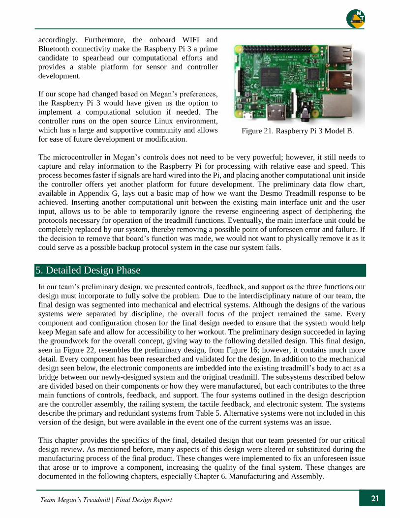
accordingly. Furthermore, the onboard WIFI and
Bluetooth connectivity make the Raspberry Pi 3 a prime
candidate to spearhead our computational efforts and
provides a stable platform for sensor and controller
development.
If our scope had changed based on Megan’s preferences,
the Raspberry Pi 3 would have given us the option to
implement a computational solution if needed. The
controller runs on the open source Linux environment,
which has a large and supportive community and allows
for ease of future development or modification.
The microcontroller in Megan’s controls does not need to be very powerful; however, it still needs to
capture and relay information to the Raspberry Pi for processing with relative ease and speed. This
process becomes faster if signals are hard wired into the Pi, and placing another computational unit inside
the controller offers yet another platform for future development. The preliminary data flow chart,
available in Appendix G, lays out a basic map of how we want the Desmo Treadmill response to be
achieved. Inserting another computational unit between the existing main interface unit and the user
input, allows us to be able to temporarily ignore the reverse engineering aspect of deciphering the
protocols necessary for operation of the treadmill functions. Eventually, the main interface unit could be
completely replaced by our system, thereby removing a possible point of unforeseen error and failure. If
the decision to remove that board’s function was made, we would not want to physically remove it as it
could serve as a possible backup protocol system in the case our system fails.
5. Detailed Design Phase
In our team’s preliminary design, we presented controls, feedback, and support as the three functions our
design must incorporate to fully solve the problem. Due to the interdisciplinary nature of our team, the
final design was segmented into mechanical and electrical systems. Although the designs of the various
systems were separated by discipline, the overall focus of the project remained the same. Every
component and configuration chosen for the final design needed to ensure that the system would help
keep Megan safe and allow for accessibility to her workout. The preliminary design succeeded in laying
the groundwork for the overall concept, giving way to the following detailed design. This final design,
seen in Figure 22, resembles the preliminary design, from Figure 16; however, it contains much more
detail. Every component has been researched and validated for the design. In addition to the mechanical
design seen below, the electronic components are imbedded into the existing treadmill’s body to act as a
bridge between our newly-designed system and the original treadmill. The subsystems described below
are divided based on their components or how they were manufactured, but each contributes to the three
main functions of controls, feedback, and support. The four systems outlined in the design description
are the controller assembly, the railing system, the tactile feedback, and electronic system. The systems
describe the primary and redundant systems from Table 5. Alternative systems were not included in this
version of the design, but were available in the event one of the current systems was an issue.
This chapter provides the specifics of the final, detailed design that our team presented for our critical
design review. As mentioned before, many aspects of this design were altered or substituted during the
manufacturing process of the final product. These changes were implemented to fix an unforeseen issue
that arose or to improve a component, increasing the quality of the final system. These changes are
documented in the following chapters, especially Chapter 6. Manufacturing and Assembly.
Figure 21. Raspberry Pi 3 Model B.

Team Megan’s Treadmill | Final Design Report
Figure 22. The solid model of the treadmill for the detailed design.
5.1 Controller Assembly
The controller assembly, seen in Figure 23, consists of the main gripping system and the control panel,
which contains the input controls. The primary system from Table 5 is a two-handed controller; however,
we updated the system to have a two-handed grip with a control box in the center. The control panel was
designed with extra space in the event it was desired to add more inputs. Both these systems were to be
attached to the horizontal rail spanning the width of the treadmill. The controller assembly is the
subsystem that Megan will be directly interfacing with most of the time; therefore, it was crucial that we
optimized it for her.
Support
Rails
Caster
Feet
Handlebars
Feedback
System
Sliding Arm
Control
Panel

Team Megan’s Treadmill | Final Design Report
Figure 23. The controller assembly of our detailed design consists of the gripping system and the control
panel.
5.1.1 Details
In the conceptual design phase, the controller assembly was general, incorporating only the concepts of
an ergonomic gripping system and accessible controls. The detailed design provides more specific
information and contains an alternate solution for the gripping system. The primary design utilizes road
bike handlebars for Megan to hold while exercising, and the backup design is a custom, angled bar grip.
The primary design of the handlebars was implemented in the final product, but both designs are
discussed in the following section. In the detailed design, the control panel is centered on and attached to
the horizontal rail. It contains a two-button switch (start and stop) located on the left side and a rotary
switch located on the right (speed level selection). Braille labels are designed to mark the buttons and
rotary switch, allowing Megan to understand the purpose of each input. This will be very helpful when
she is getting familiar with the controls. The control panel was designed to be attached with brackets
while the gripping system would be welded to plates slotted into the horizontal rail.
5.1.2 Analysis
As mentioned before, Megan will be interfacing constantly with the controller assembly, so it must be
ergonomic and accessible. Specifically, the gripping system was designed to be comfortable for Megan’s
hands and overall upper-body posture. Our team measured Megan’s hand to compare to anthropometric
data to determine the optimal size of the diameter of the grips. The data consists of five main
measurements of the hand including the total hand length and width, and finger length. This data and
Megan’s personal measurements can be found in Appendix H. Precise measurements are hard to obtain;
however, Megan’s hand size falls somewhere between the 5th and 50th percentiles5. The maximum grip
diameter for females of the 5th percentile is 43 millimeters or about 1.69 inches. Based on this data, our
team proposed a diameter size of the grips between 1 and 1.5 inches, which is smaller than the maximum
grip size for the 5th percentile. On the other hand, we wanted to ensure the grip was not too small as that
would force Megan to squeeze tightly to obtain a secure grip. The road bike handlebars are made of
tubing slightly less than 1 inch in diameter; however, the addition of grip tape increases this measurement
and was found to be comfortable to Megan.
Team Megan’s Treadmill | Final Design Report
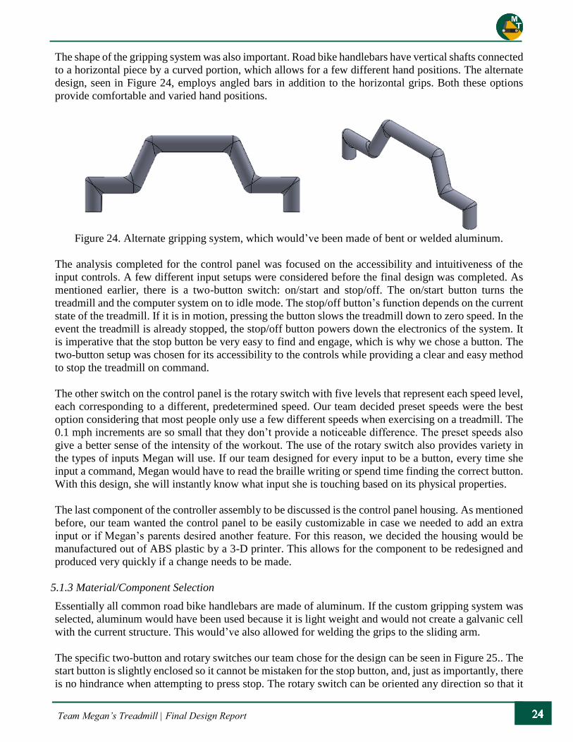
The shape of the gripping system was also important. Road bike handlebars have vertical shafts connected
to a horizontal piece by a curved portion, which allows for a few different hand positions. The alternate
design, seen in Figure 24, employs angled bars in addition to the horizontal grips. Both these options
provide comfortable and varied hand positions.
Figure 24. Alternate gripping system, which would’ve been made of bent or welded aluminum.
The analysis completed for the control panel was focused on the accessibility and intuitiveness of the
input controls. A few different input setups were considered before the final design was completed. As
mentioned earlier, there is a two-button switch: on/start and stop/off. The on/start button turns the
treadmill and the computer system on to idle mode. The stop/off button’s function depends on the current
state of the treadmill. If it is in motion, pressing the button slows the treadmill down to zero speed. In the
event the treadmill is already stopped, the stop/off button powers down the electronics of the system. It
is imperative that the stop button be very easy to find and engage, which is why we chose a button. The
two-button setup was chosen for its accessibility to the controls while providing a clear and easy method
to stop the treadmill on command.
The other switch on the control panel is the rotary switch with five levels that represent each speed level,
each corresponding to a different, predetermined speed. Our team decided preset speeds were the best
option considering that most people only use a few different speeds when exercising on a treadmill. The
0.1 mph increments are so small that they don’t provide a noticeable difference. The preset speeds also
give a better sense of the intensity of the workout. The use of the rotary switch also provides variety in
the types of inputs Megan will use. If our team designed for every input to be a button, every time she
input a command, Megan would have to read the braille writing or spend time finding the correct button.
With this design, she will instantly know what input she is touching based on its physical properties.
The last component of the controller assembly to be discussed is the control panel housing. As mentioned
before, our team wanted the control panel to be easily customizable in case we needed to add an extra
input or if Megan’s parents desired another feature. For this reason, we decided the housing would be
manufactured out of ABS plastic by a 3-D printer. This allows for the component to be redesigned and
produced very quickly if a change needs to be made.
5.1.3 Material/Component Selection
Essentially all common road bike handlebars are made of aluminum. If the custom gripping system was
selected, aluminum would have been used because it is light weight and would not create a galvanic cell
with the current structure. This would’ve also allowed for welding the grips to the sliding arm.
The specific two-button and rotary switches our team chose for the design can be seen in Figure 25.. The
start button is slightly enclosed so it cannot be mistaken for the stop button, and, just as importantly, there
is no hindrance when attempting to press stop. The rotary switch can be oriented any direction so that it

Team Megan’s Treadmill | Final Design Report
will be most intuitive for Megan. As explained in the last section, the control panel housing will be made
with ABS plastic. There is no need for this controller housing to be made of a stronger material because
it won’t be taking any significant loads, and ABS is ideal because of the low cost and specific stiffness.
Figure 25. The two-button input and rotary switch specified in the detailed design of the control panel.
5.2 Railing Assembly
Shown in Figure 26, the railing assembly is the main component that makes up the primary structure of
the support system. The Woodway Desmo treadmill does have side rails equipped; however, they are not
comfortable to grip for an extended period. The side railing’s two primary goals are helping Megan keep
her balance and providing different feedback to Megan and the on-board computer. The railing system
is designed to be fixed to the ground to provide a sturdy frame to assist Megan’s balance throughout her
workout. While the side rails remain fixed, the middle bar is free to move in one dimension along the
treadmill.
Figure 26. Solidworks assembly of the detailed design of the railing system.

Team Megan’s Treadmill | Final Design Report
5.2.1 Details
The treadmill is approximately 70” long, 38” wide and 62” tall. The new side rails extend past the length
of the treadmill and are placed in between the treadmill’s existing side rails at a distance of approximately
24” apart. Based on measurements of Megan’s elbow and hand positions while on the treadmill, an initial
height for the bars was set at 48” from the ground (the treadmill base is approximately 9” tall). The side
rails, made from T-Slot Aluminum, are a straight forward design focused on supporting Megan. The
more complex system is the sliding controller. The initial design for the sliding component was a
stationary bar rigidly connected to the side rails with a controller attached to a telescoping arm that moved
forward and backward. This method was replaced with a middle bar that slides along the side rails, with
the controller assembly rigidly attached.
5.2.2 Analysis
The two main features analyzed for the railing system were the tolerances for the assembly and the
identification of a proper linear telescoping method for the controller. Initially, the railing system was
going to use telescoping structural square tubing to provide a sturdy frame at a low cost; however, there
were a few problems with this method. The initial analysis performed looked at the structural strength of
the square tubing. A static load, using a conservative estimate of Megan’s weight multiplied by a safety
factor of two was applied. Due to the small load, this test passed with a large margin of safety, as seen in
Table 6.
Table 6. Initial structural analysis of square structural tubing.
Material 1018 CD Units
Outer Section Length (a) 1.5 in
Inner Section Length (b) 1.25 in
Length of Tubing (l) 12 in
Ultimate Strength (Fult) 53700 psi
Young's Modulus (E) 2.97E+07 psi
Shear Modulus (G) 1.16E+07 psi
Area Moment of Inertia (I) 0.2184 in^4
Section Modulus (Z) 0.2912 in^3
Radius of Gyration 0.5637 in
Cross Section Area (A) 0.6875 in^2
Case 1: Pure Axial Loading
Applied Load (P) 150 lbf
Safety Factor (FS) 2 -
Axial Stress 3600 psi
Axial Deflection (d) 0.00018 in
Case 2: Applied Moment
Moment (M) 225 lbf-in
Transverse Stress 12361 psi
Transverse Deflection (y) 0.0266 in
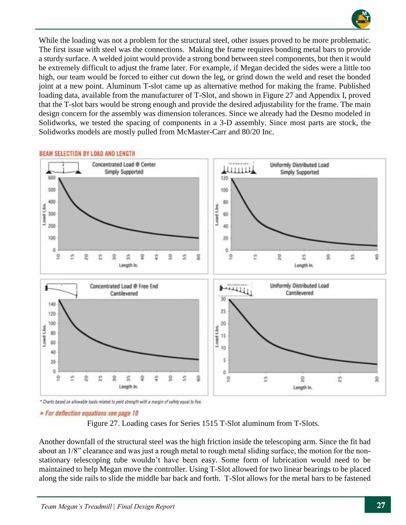
Team Megan’s Treadmill | Final Design Report
While the loading was not a problem for the structural steel, other issues proved to be more problematic.
The first issue with steel was the connections. Making the frame requires bonding metal bars to provide
a sturdy surface. A welded joint would provide a strong bond between steel components, but then it would
be extremely difficult to adjust the frame later. For example, if Megan decided the sides were a little too
high, our team would be forced to either cut down the leg, or grind down the weld and reset the bonded
joint at a new point. Aluminum T-slot came up as alternative method for making the frame. Published
loading data, available from the manufacturer of T-Slot, and shown in Figure 27 and Appendix I, proved
that the T-slot bars would be strong enough and provide the desired adjustability for the frame. The main
design concern for the assembly was dimension tolerances. Since we already had the Desmo modeled in
Solidworks, we tested the spacing of components in a 3-D assembly. Since most parts are stock, the
Solidworks models are mostly pulled from McMaster-Carr and 80/20 Inc.
Figure 27. Loading cases for Series 1515 T-Slot aluminum from T-Slots.
Another downfall of the structural steel was the high friction inside the telescoping arm. Since the fit had
about an 1/8” clearance and was just a rough metal to rough metal sliding surface, the motion for the non-
stationary telescoping tube wouldn’t have been easy. Some form of lubrication would need to be
maintained to help Megan move the controller. Using T-Slot allowed for two linear bearings to be placed
along the side rails to slide the middle bar back and forth. T-Slot allows for the metal bars to be fastened

Team Megan’s Treadmill | Final Design Report
together due to an extrusion along the edges. The cross section of a T-Slot bar can be seen in Figure 28.
A 1.5-inch width square bar was selected based on the measurements of Megan’s hand, and because it
compared to the grips on the current treadmill. The measurements were also compared to the published
grip sizing for Megan’s hand size.5
Figure 28. Cross section of aluminum T-Slot.
The next component analyzed for the detailed design was the sliding arm, which allows Megan to move
fluidly along the treadmill, while giving the treadmill feedback of Megan’s location on the treadmill. The
sliding assembly is mounted to the side rails in two places. There are two bearings positioned on each
side rail: one that is stationary and one that slides. The middle bar is fastened to the two moving, linear
bearings that are free to move along the side rails. The original design utilized linear gas springs to help
restrict the movement of the linear bearings, as seen in Figure 29. Once the linear bearings were installed,
we found the gas springs to be unnecessary because of the natural resistance between the T-Slot and
linear bearings.
Figure 29. Detailed design of the sliding arm configuration with linear speed limiters.

Team Megan’s Treadmill | Final Design Report
5.2.3 Material/Component Selection
For our detailed design, the frame was specified to be built with aluminum T-Slot extrusions. All the
brackets, linear bearings, and mounting equipment were to be made of aluminum as well. The exception
to the aluminum are the zinc-coated steel fasteners and the stainless steel linear speed limiter. Zinc coated
steel and stainless steel do not typically corrode with aluminum under standard atmospheric conditions,
and the treadmill will ultimately remain in a stable home environment. The 15 series (1.5” x 1.5” cross
section) grade of T-Slot was chosen over the 10 series (1.00”x1.00” cross section) because it is stronger
and provides an easier grip size for Megan. Plastic T-Slot covers were inserted along the railing to provide
a smooth surface for Megan to hold onto. An exploded assembly of the mechanical components, from
the Critical Design phase, for the rail system can be seen in and in Appendix J.
The fasteners for the T-Slot are specified in the catalog, but are generally a 5/16”-18 thread. One
component that was not confirmed in this detailed design was the base leveling foot. The treadmill will
ultimately go to Megan’s home; however, the exact location and its conditions were uncertain at this
stage. The selection of this component will be discussed in Chapter 6.
5.3 Tactile Positioning Feedback System
The tactile positioning feedback system was designed based on the ideation concept of material feedback
as a redundant system. The concept was renamed to more accurately describe the system and its function.
With Megan holding onto the grips with both hands, there is very little chance of lateral motion towards
the sides of the treadmill. If she is only using one hand to hold on though, this chance increases. The side
rails are present to help ensure Megan does not step off the side of the treads; however, the tactile
positioning feedback system was designed as a redundant safety system to alert Megan as to her position
on the treadmill.
5.3.1 Details
There were many attributes of this system that were researched and evaluated to find the best solution.
These aspects included the type of material, the amount of the material, where it is located on the treads,
its firmness, and how it could be attached. Some physical testing was completed to estimate the optimal
positioning of the material. We determined that every other tread would have a bumper 2 in. from either
ends of the tread. This may seem to provide very little room for error; however, the width of each tread
is only 20 in. When walking on a treadmill, lateral motion is not very natural so to traverse more than 2
in. laterally in a single step is extremely unlikely. The positioning of the material on each tread can be
seen in Figure 30.
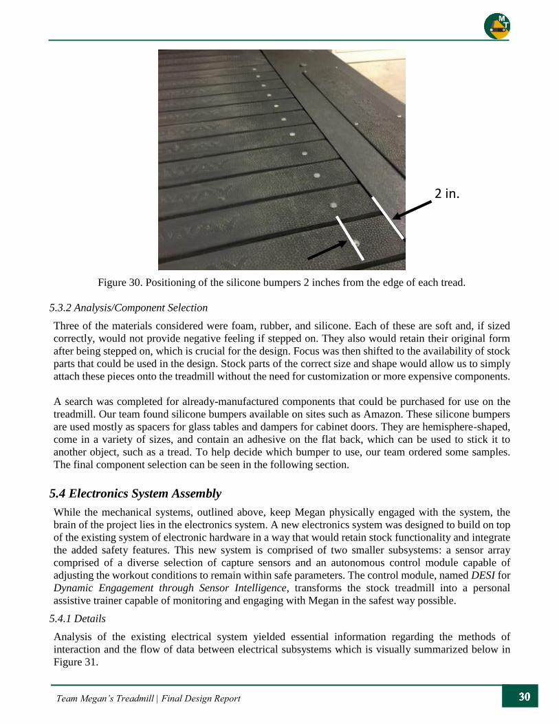
Team Megan’s Treadmill | Final Design Report
Figure 30. Positioning of the silicone bumpers 2 inches from the edge of each tread.
5.3.2 Analysis/Component Selection
Three of the materials considered were foam, rubber, and silicone. Each of these are soft and, if sized
correctly, would not provide negative feeling if stepped on. They also would retain their original form
after being stepped on, which is crucial for the design. Focus was then shifted to the availability of stock
parts that could be used in the design. Stock parts of the correct size and shape would allow us to simply
attach these pieces onto the treadmill without the need for customization or more expensive components.
A search was completed for already-manufactured components that could be purchased for use on the
treadmill. Our team found silicone bumpers available on sites such as Amazon. These silicone bumpers
are used mostly as spacers for glass tables and dampers for cabinet doors. They are hemisphere-shaped,
come in a variety of sizes, and contain an adhesive on the flat back, which can be used to stick it to
another object, such as a tread. To help decide which bumper to use, our team ordered some samples.
The final component selection can be seen in the following section.
5.4 Electronics System Assembly
While the mechanical systems, outlined above, keep Megan physically engaged with the system, the
brain of the project lies in the electronics system. A new electronics system was designed to build on top
of the existing system of electronic hardware in a way that would retain stock functionality and integrate
the added safety features. This new system is comprised of two smaller subsystems: a sensor array
comprised of a diverse selection of capture sensors and an autonomous control module capable of
adjusting the workout conditions to remain within safe parameters. The control module, named DESI for
Dynamic Engagement through Sensor Intelligence, transforms the stock treadmill into a personal
assistive trainer capable of monitoring and engaging with Megan in the safest way possible.
5.4.1 Details
Analysis of the existing electrical system yielded essential information regarding the methods of
interaction and the flow of data between electrical subsystems which is visually summarized below in
Figure 31.
2 in.

Team Megan’s Treadmill | Final Design Report
As mentioned in Section 4.3 Computer & Electrical Systems, the existing electrical system uses three
logic boards to perform all tasks associated with basic operation. The lines of communication used to
relay information between the boards were traced and probed to gather necessary information regarding
electrical compatibility. Since the schematics of the logic boards are not available for reference, special
attention was placed into identifying places where access would be the safest and most viable option.
Three methods of entry, visually shown in Figure 32, were found in the existing system, of which the J10
connection was deemed the best injection site since the communications across that line were still not yet
acted upon by the main interface. This meant that an external source could route these communication
signals to its location and reinterpret them in a manner of the source’s choosing before sending them back
emulating the original user interface panel. A second control interface, DESI, is designed to employ this
technique to operate the treadmill autonomously using real time sensor data to provide the safest possible
workout environment for Megan. A key detail going forward, however, is the possibility that the DB9
port, shown in blue in Figure 32, could be a more viable option for command injection into the main
interface unit. While this is still not yet fully confirmed, if authentication is not performed by the main
interface unit at the site during the RS232 handshake, then a USB to Serial adapter would be a simpler
and more cost-effective option. Regardless, both methods of entry achieve the same purpose and are
considered as substitutable protocols moving forward.
Figure 31: A simplified model of the existing electrical system.

Team Megan’s Treadmill | Final Design Report
To summarize, the new electronics system assembly consists of two core subsystems and a smaller
optional subsystem, which allow for seamless integration into the existing hardware of the treadmill.
DESI: Dynamic Engagement through Sensor Intelligence
The core component of the electronics system assembly is the central control unit which, through
continuous sensor readings and user input, provides a safe workout experience for Megan.
Sensor Grid:
The variety of sensors provides the necessary information to DESI to operate the treadmill. The sensor
grid gathers information about Megan’s status on the treadmill, and gives feedback to the central control
unit.
Gate Module:
This key component allows us to control the source of the input location from either the stock user
interface or directly from the DESI communication. It also acts as a buffer and signal booster as DESI is
not able to produce high voltage swings like those seen on the RS232 protocol.
5.4.2 Analysis
DESI: Dynamic Engagement through Sensor Intelligence
Many treadmill accidents occur when the user loses track of their position on the treadmill, leading to a
temporary vertigo, or fails to keep up with the selected speed. The latter is then compounded by the
inability to reach the speed controls usually placed at the front of a treadmill, as is the case with our
Woodway Desmo.
Figure 32. Breakdown of interface board: methods of entry.

Team Megan’s Treadmill | Final Design Report
The mechanical systems and controller eliminate this source of instability by restricting lateral movement
and by keeping Megan within range of the controls. However, we still believe the safest location for
Megan is in the first 20 cm of drift backward, allowable by the sliding arm. One solution is the constant
readjustment of speed in the situation where too much backward drift was detected. Since the system is
to be as self-sustaining as possible, a way the new control module could perform this constant checking
and correcting was developed.
Although far from being considered artificial intelligence, the programming behind DESI was inspired
by the actions of Megan’s supervisors during her workouts and the idea of introducing self-responsive
feedback loop that would drive the system to a point of assured safety. Twin ultrasonic sensors statically
positioned on each sliding arm capture the distance traveled in the negative Y direction as shown in
Figure 33. Using this distance, DESI can then decide whether Megan is in a stable region or has traveled
too far towards the end of the treadmill. Furthermore, if the distance is deemed to fall into this region, a
correction of speed is directly issued to the main interface unit. After this correction is issued, DESI
probes the sensors again to check if there was an improvement in location and reissues another correction
until the speed is lowered enough to where Megan can reenter the safe zone of operation.
Figure 33. Detailed design location of various sensors on the railing assembly.
The speed adjustment loop relies on the sensor data provided by the ultrasonic sensors to be accurate, or
unnecessary interruptions of speed will occur when corrupt data is received: hence, why two sensors are
used instead of one. Validity checks are performed on inputs as they are received to ascertain that the
error between both distances received are within an acceptable bound.
Handlebars Handlebars Capacitive
Sensors
Proximity
Sensors
Proximity
Sensors Microphone/
Camera
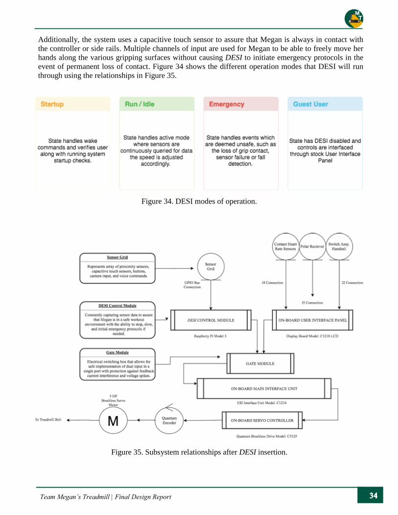
Team Megan’s Treadmill | Final Design Report
Additionally, the system uses a capacitive touch sensor to assure that Megan is always in contact with
the controller or side rails. Multiple channels of input are used for Megan to be able to freely move her
hands along the various gripping surfaces without causing DESI to initiate emergency protocols in the
event of permanent loss of contact. Figure 34 shows the different operation modes that DESI will run
through using the relationships in Figure 35.
Figure 35. Subsystem relationships after DESI insertion.
Figure 34. DESI modes of operation.
Team Megan’s Treadmill | Final Design Report
Sensor Grid:
For DESI to accurately determine the belt speed and workout conditions, it relies on a grid of sensors that
continuously capture and relay data. Two ultrasonic proximity sensors mounted on the railing assembly
monitor the distance that Megan has traveled backward from the natural resting position of the rails.
Capacitive grip sensors mounted to the inside of Megan’s contact points on the gripping surfaces give
insight to the presence of Megan and vitals such as temperature and heartrate. These sensors also act as
an emergency stop. as loss of contact immediately terminates the workout and places the system in
emergency mode. Although the camera that monitors Megan is only active in emergency mode, it too
can be queried by DESI and could provide feedback such as motion detection.
With the current stock treadmill, when the user enters a command on the user interface unit (Figure. 18,
Red), that command triggers the logic board within that subsystem. This subsystem finds the location
and function of the command entered and then stores the status of the treadmill in its local memory.
Concurrently, a series of electrical signals are issued down a 7-pin cable directly into the J10 port
connection on the main interface unit where it gets translated and acted upon. This process of
communication must remain intact if we wish to retain all stock functionality. Accordingly, a special
module called GATE is necessary to act as a “high-tech crossing guard” in that it will only allow input
from one line to enter the main interface unit at any given time. After analyzing all incoming input, DESI
either issues a correction to the speed of the belt, however minute it might be. To accomplish this, DESI
translates the correction command into a series of electrical signals that exactly matches what the stock
board would issue for that same command.
This allows us to maintain all stock functionality as a default, in case guest users wish to use the treadmill
system, and minimizes errors since the existing onboard error system would check the incoming input a
second time after acceptance.
5.4.3 Component Selection
Control Unit Platform Selection
As mentioned in the preliminary interface plan, the chosen platform for the central control unit needs to
be one with more computing power than the average microcontroller. After looking for cheaper
alternatives, it was clear that the Raspberry Pi 3 module was the best choice when considering stock
onboard features, available support, and portability with respect to cost. Table 8 demonstrates the
favorability of the Raspberry Pi 3 module in contrast to other platforms taken into consideration.

Team Megan’s Treadmill | Final Design Report
Table 8. Specifications of various possible control units.
As with most generic developer chipsets, the Raspberry Pi 3 is bundled with a large selection of external
features such as an onboard WIFI receiver and four available USB 2.0, which gives us a large integration
set for only $40. Other boards such as the BeagleBone have built in analog to digital converters, which
would have been useful during integration of the sensors, but it offers less in terms of community support.
Proximity Sensor Selection
The DESI control system requires constant knowledge of where Megan is positioned on the treadmill to
accurately and safely maintain a workout state. There are multiple ways in gaining this information such
as using an infrared or ultrasonic sensor. The SR04 ultrasonic sensor was selected for its acceptable
accuracy and superior price point.
Table 9. Possible electronic proximity sensor components.
Sharp IR MaxBotix EZ0 SR04 MaxBotix EZ1
Cost $20.00 $29.95 $6.95 $49.95
Accuracy 71% 87% 67% 99%
Type IR Ultrasonic Ultrasonic Ultrasonic
BeagleBone
Black Intel Galileo Raspberry Pi 3 Arduino Yun
Cost $55.00 $79.95 $39.95 $44.95
Support Forums Intel Forums RPi Foundation
Arduino
Community
CPU ARM v7 Intel Quark1000 ARM v7 ATMega32u
Speed 1.0 GHz 400 MHz 1.2 GHz 400 MHz
Inputs 57 34 30 25
USB 1 1 4 1
Memory 512 MB 256 MB 512 MB 128 MB
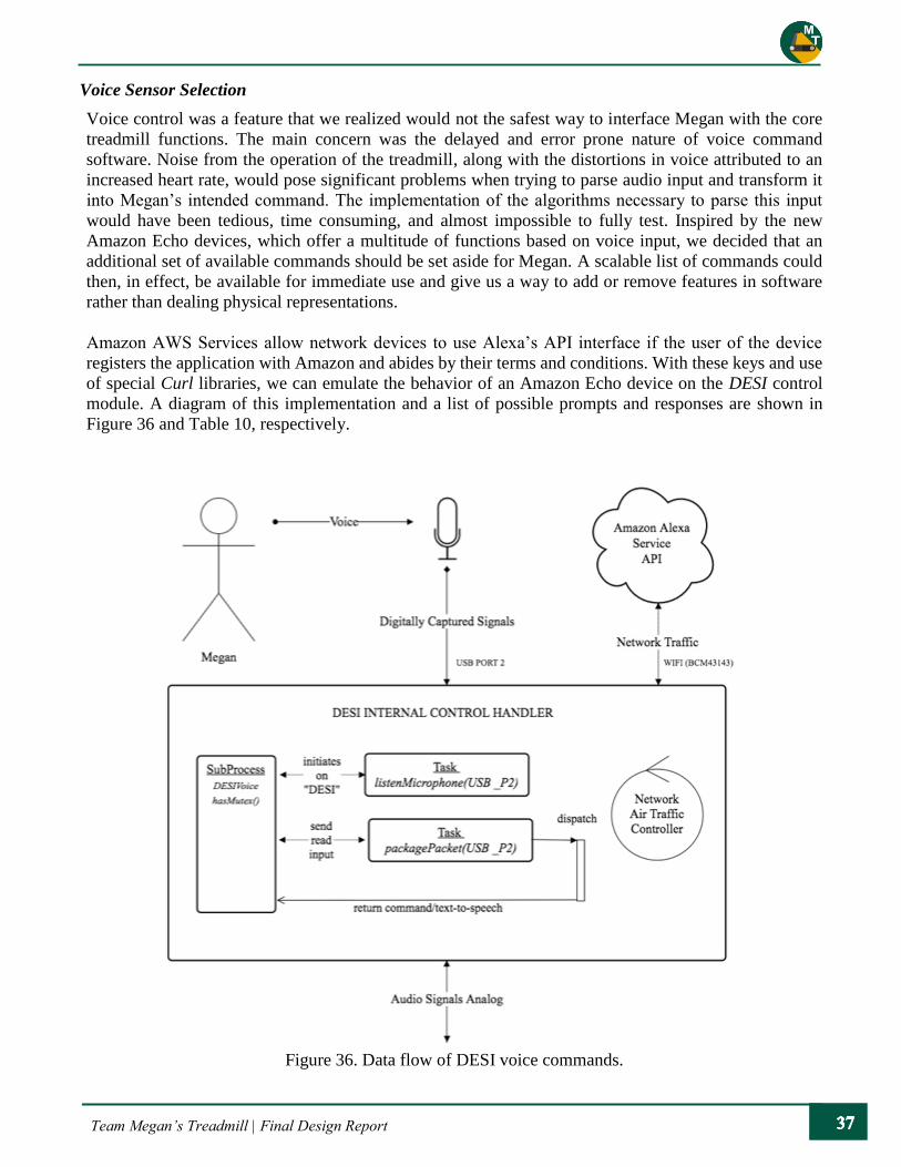
Team Megan’s Treadmill | Final Design Report
Voice Sensor Selection
Voice control was a feature that we realized would not the safest way to interface Megan with the core
treadmill functions. The main concern was the delayed and error prone nature of voice command
software. Noise from the operation of the treadmill, along with the distortions in voice attributed to an
increased heart rate, would pose significant problems when trying to parse audio input and transform it
into Megan’s intended command. The implementation of the algorithms necessary to parse this input
would have been tedious, time consuming, and almost impossible to fully test. Inspired by the new
Amazon Echo devices, which offer a multitude of functions based on voice input, we decided that an
additional set of available commands should be set aside for Megan. A scalable list of commands could
then, in effect, be available for immediate use and give us a way to add or remove features in software
rather than dealing physical representations.
Amazon AWS Services allow network devices to use Alexa’s API interface if the user of the device
registers the application with Amazon and abides by their terms and conditions. With these keys and use
of special Curl libraries, we can emulate the behavior of an Amazon Echo device on the DESI control
module. A diagram of this implementation and a list of possible prompts and responses are shown in
Figure 36 and Table 10, respectively.
Figure 36. Data flow of DESI voice commands.

Team Megan’s Treadmill | Final Design Report
Table 10. List of DESI voice commands and responses.
Commands Variations Action
“Hello” Hey, Hi, Howdy, Greetings,
What’s Up Replies to asker, “Hello.”
“How fast am I going” How fast, Say Speed Replies to asker:
[Current Speed]
“How far have I traveled” How far, Say distance Replies to asker:
[Current Distance Travelled]
“Play music” Music, tunes, jams Replies to asker: “Okay”
[Actions Music Library Task]
Camera Feed Selection
Although the camera system is only activated when Megan’s parents activate the camera or the treadmill
enters emergency mode, it was still essential to choose a system that is reliable and efficient when
capturing data. Video capture and relay is a memory and processing heavy operation, and the less we
load on the DESI handler, the smoother the sensor loop feedback performs. Because of this, the native
Raspberry PiCam, shown in Figure 37, was chosen to be the visual capture unit. Since the Raspberry Pi
3 has a Camera specific port built into it, as well as the driver built into the underlying operating system,
the use of an external library and is not needed. This means less overhead for the DESI Handler and more
efficiency in the overall system.
Capacitive Sensor Selection
To detect Megan’s presence on the treadmill, we needed a way to verify she was gripping the controls
with her hands. Initially, we believed that the proximity sensors would perform that task; however, after
noticing problems in the way the SR-04 sensors handled detecting clothing and moving objects, we opted
for a direct line of communication to her hands. A capacitive sensor would allow us to detect current
flow out of a set of 12 channels along the gripping surfaces to verify that Megan’s contact with the support
system. Availability of this type of sensor is limited, but the MPR121 by Adafruit is the most efficient
and cost effective at $7.95.
Figure 37. The Raspberry PiCam and ribbon attachment cable.

Team Megan’s Treadmill | Final Design Report
6. Manufacturing and Assembly
As discussed in the previous two chapters, many aspects of the detailed design were changed during the
manufacturing phase. As our team worked through the implementation of our various systems, it became
clear that some adjustments and adaptations were necessary to produce the best product possible. As with
the other phases of this project, the fabrication was divided between the mechanical and electrical
systems, culminating in the integration of the two. The realization of our final product and the major
changes are highlighted in this chapter.
6.1 Mechanical Systems
The first step in the mechanical process was to assemble the aluminum T-Slot to form the rails along the
treadmill. The T-Slot was cut to length before being shipped and was validated when the parts arrived.
All the rails were laid out to check for proper clearance with the existing treadmill and were then joined
together using fasteners for the T-Slot. The original design had the rails sitting on caster feet; however,
when the rails were put together, it was clear that the caster feet did not provide the needed stability to
support Megan safely while on the treadmill. The caster feet were replaced with base feet that were bolted
down to a ¾” thick plywood base, which sits underneath the treadmill. The weight of the treadmill ensures
that the plywood provides a stable and rigid base. The plywood was then painted black for aesthetics and
to help detect any future cracks or chips in the wood. The difference between the two mounting bases
can be seen in Figure 38.
Figure 38. The difference between the original caster foot (left) and the implemented base foot bolted
down to plywood (right).
Once the vertical supports were established, the horizontal bars were placed along the treadmill and
fastened with T-Slot specific bolts and nuts. Cross bars were added for increased stability, and one linear
bearing was placed on each rail. A picture of the barebones model can be seen in Figure 39.
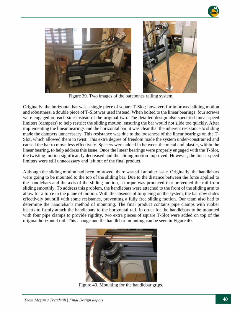
Team Megan’s Treadmill | Final Design Report
Figure 39. Two images of the barebones railing system.
Originally, the horizontal bar was a single piece of square T-Slot; however, for improved sliding motion
and robustness, a double piece of T-Slot was used instead. When bolted to the linear bearings, four screws
were engaged on each side instead of the original two. The detailed design also specified linear speed
limiters (dampers) to help restrict the sliding motion, ensuring the bar would not slide too quickly. After
implementing the linear bearings and the horizontal bar, it was clear that the inherent resistance to sliding
made the dampers unnecessary. This resistance was due to the looseness of the linear bearings on the T-
Slot, which allowed them to twist. This extra degree of freedom made the system under-constrained and
caused the bar to move less effectively. Spacers were added in between the metal and plastic, within the
linear bearing, to help address this issue. Once the linear bearings were properly engaged with the T-Slot,
the twisting motion significantly decreased and the sliding motion improved. However, the linear speed
limiters were still unnecessary and left out of the final product.
Although the sliding motion had been improved, there was still another issue. Originally, the handlebars
were going to be mounted to the top of the sliding bar. Due to the distance between the force applied to
the handlebars and the axis of the sliding motion, a torque was produced that prevented the rail from
sliding smoothly. To address this problem, the handlebars were attached to the front of the sliding arm to
allow for a force in the plane of motion. With the absence of torqueing on the system, the bar now slides
effectively but still with some resistance, preventing a fully free sliding motion. Our team also had to
determine the handlebar’s method of mounting. The final product contains pipe clamps with rubber
inserts to firmly attach the handlebars to the horizontal rail. In order for the handlebars to be mounted
with four pipe clamps to provide rigidity, two extra pieces of square T-Slot were added on top of the
original horizontal rail. This change and the handlebar mounting can be seen in Figure 40.
Figure 40. Mounting for the handlebar grips.
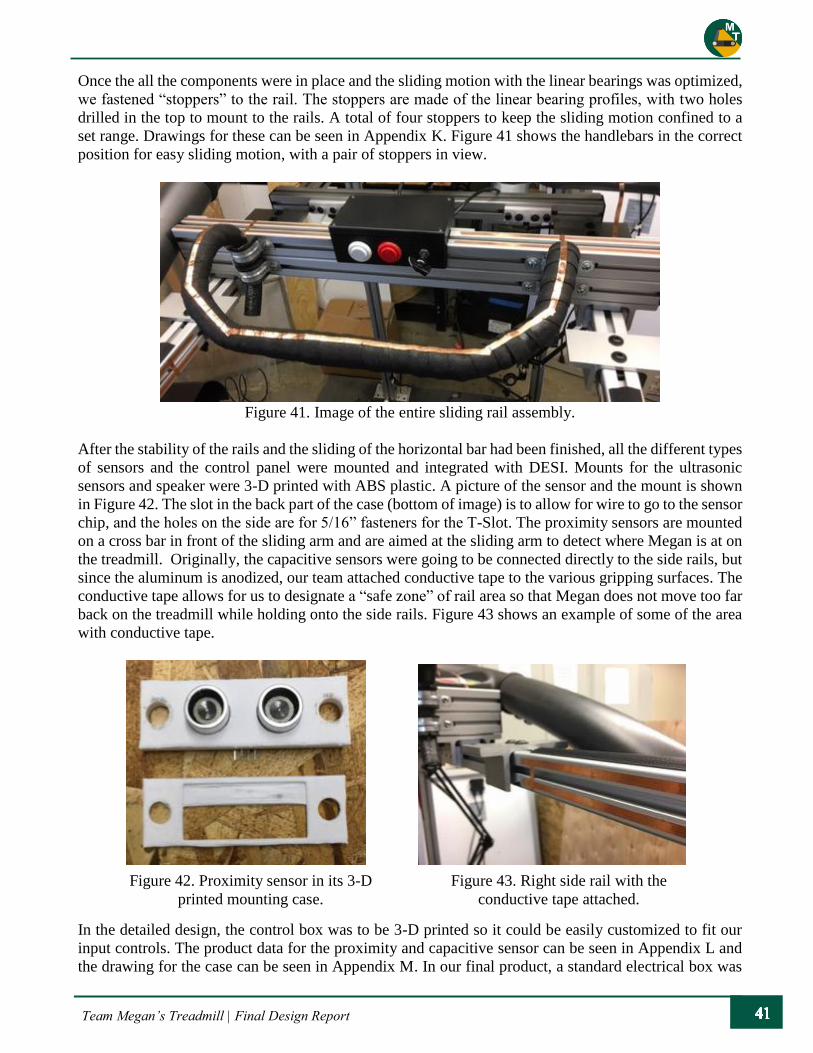
Team Megan’s Treadmill | Final Design Report
Once the all the components were in place and the sliding motion with the linear bearings was optimized,
we fastened “stoppers” to the rail. The stoppers are made of the linear bearing profiles, with two holes
drilled in the top to mount to the rails. A total of four stoppers to keep the sliding motion confined to a
set range. Drawings for these can be seen in Appendix K. Figure 41 shows the handlebars in the correct
position for easy sliding motion, with a pair of stoppers in view.
Figure 41. Image of the entire sliding rail assembly.
After the stability of the rails and the sliding of the horizontal bar had been finished, all the different types
of sensors and the control panel were mounted and integrated with DESI. Mounts for the ultrasonic
sensors and speaker were 3-D printed with ABS plastic. A picture of the sensor and the mount is shown
in Figure 42. The slot in the back part of the case (bottom of image) is to allow for wire to go to the sensor
chip, and the holes on the side are for 5/16” fasteners for the T-Slot. The proximity sensors are mounted
on a cross bar in front of the sliding arm and are aimed at the sliding arm to detect where Megan is at on
the treadmill. Originally, the capacitive sensors were going to be connected directly to the side rails, but
since the aluminum is anodized, our team attached conductive tape to the various gripping surfaces. The
conductive tape allows for us to designate a “safe zone” of rail area so that Megan does not move too far
back on the treadmill while holding onto the side rails. Figure 43 shows an example of some of the area
with conductive tape.
In the detailed design, the control box was to be 3-D printed so it could be easily customized to fit our
input controls. The product data for the proximity and capacitive sensor can be seen in Appendix L and
the drawing for the case can be seen in Appendix M. In our final product, a standard electrical box was
Figure 42. Proximity sensor in its 3-D
printed mounting case.
Figure 43. Right side rail with the
conductive tape attached.
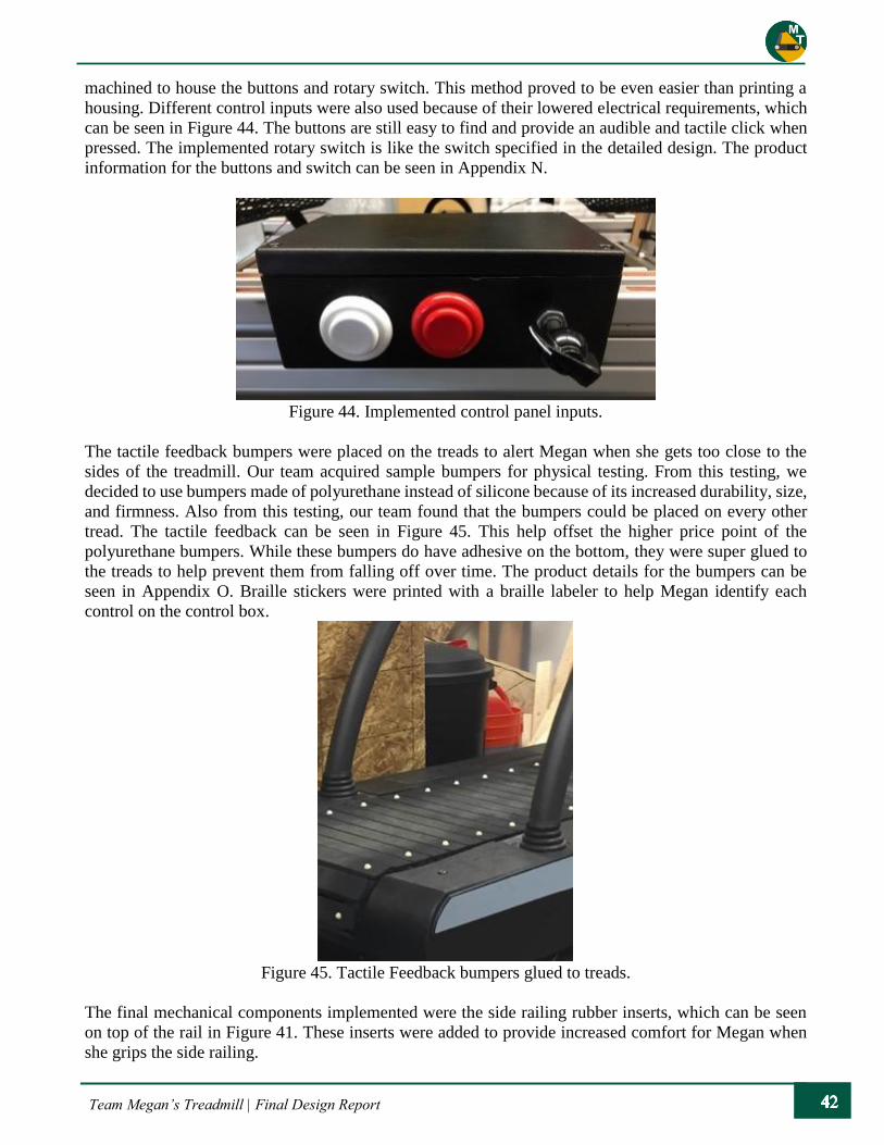
Team Megan’s Treadmill | Final Design Report
machined to house the buttons and rotary switch. This method proved to be even easier than printing a
housing. Different control inputs were also used because of their lowered electrical requirements, which
can be seen in Figure 44. The buttons are still easy to find and provide an audible and tactile click when
pressed. The implemented rotary switch is like the switch specified in the detailed design. The product
information for the buttons and switch can be seen in Appendix N.
Figure 44. Implemented control panel inputs.
The tactile feedback bumpers were placed on the treads to alert Megan when she gets too close to the
sides of the treadmill. Our team acquired sample bumpers for physical testing. From this testing, we
decided to use bumpers made of polyurethane instead of silicone because of its increased durability, size,
and firmness. Also from this testing, our team found that the bumpers could be placed on every other
tread. The tactile feedback can be seen in Figure 45. This help offset the higher price point of the
polyurethane bumpers. While these bumpers do have adhesive on the bottom, they were super glued to
the treads to help prevent them from falling off over time. The product details for the bumpers can be
seen in Appendix O. Braille stickers were printed with a braille labeler to help Megan identify each
control on the control box.
Figure 45. Tactile Feedback bumpers glued to treads.
The final mechanical components implemented were the side railing rubber inserts, which can be seen
on top of the rail in Figure 41. These inserts were added to provide increased comfort for Megan when
she grips the side railing.
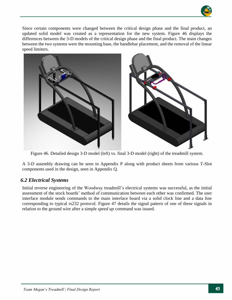
Team Megan’s Treadmill | Final Design Report
Since certain components were changed between the critical design phase and the final product, an
updated solid model was created as a representation for the new system. Figure 46 displays the
differences between the 3-D models of the critical design phase and the final product. The main changes
between the two systems were the mounting base, the handlebar placement, and the removal of the linear
speed limiters.
Figure 46. Detailed design 3-D model (left) vs. final 3-D model (right) of the treadmill system.
A 3-D assembly drawing can be seen in Appendix P along with product sheets from various T-Slot
components used in the design, seen in Appendix Q.
6.2 Electrical Systems
Initial reverse engineering of the Woodway treadmill’s electrical systems was successful, as the initial
assessment of the stock boards’ method of communication between each other was confirmed. The user
interface module sends commands to the main interface board via a solid clock line and a data line
corresponding to typical rs232 protocol. Figure 47 details the signal pattern of one of these signals in
relation to the ground wire after a simple speed up command was issued.

Team Megan’s Treadmill | Final Design Report
The signals coming from the user interface board were measured with a Rigol DS1054Z, 50 MHz
oscilloscope, and they revealed that a swing voltage of around 10 volts DC was being used. This was
concerning because it was much higher than the normal operating voltage of the Raspberry Pi 3 module.
Furthermore, as more signals were analyzed, our team encountered abnormalities in the pattern of sending
and receiving signals. Figure 48 shows a strange signal pulse that was periodically sent to the main
interface board even when no command had been issued. Since it did not increase or decrease in relation
to different speeds, we ruled out any typical application of the signal such as pulse-width modulation or
status code sending. After a few weeks spent analyzing these signals with no real progress, a decision
was made to fall back to a secondary method of accessing the controls of the treadmill.
6.2.1 Wired Systems
The decision to access the controls through a secondary method was not based solely on the inability to
confirm the purpose of the signals discovered on the oscilloscope. Special precautions and circuitry were
Figure 47. Oscilloscope capture of speed up command.
Figure 48. Unknown periodic control signal sent to main interface module.

Team Megan’s Treadmill | Final Design Report
necessary to step down the high voltage signals to those which were safe for the Raspberry Pi 3 module
to read and recreate. Research into voltage level converters was performed to evaluate whether variations
of fast-switching modules would be enough to step down signals to a voltage low enough to safely enter
the Raspberry Pi 3 general purpose input/output pins (GPIO pins).
Additionally, after searching for procedural documents relevant to the use of serial on the Raspberry Pi
3 module, our team found that modifying libraries and creating the code to make the necessary tweaks
would be excessive, tedious, and error prone.
Our team transitioned to the secondary method of access into the treadmill’s controls, being sure not to
disturb the robust functionality of the stock treadmill.
\
The exposed user interface board with the J14 connector, uncoupled from the touchpad controls,
remained on the treadmill throughout the wiring process. These pins were divided into groups of high
voltages capping at 3.3 volts, pins directly tied to ground, and one specific pin with a periodic signal.
This pin was later confirmed to control the keypad logic on the stock touchpad of the treadmill. As seen
on the computer board, these pins are traced upward and taken directly underneath the resistive touch
LCD screen. These pins also attach to a set of pins on the backside of the board. Figure 49 shows the
molex connector, which exposed certain patterns of pins that were attached to the connector on the front
of the board. Following these connections, we discovered that the rail controls were directly tied to these
pins, and that they reacted to simple state changes from low voltage when pressed and active high voltage
when released.
Figure 49. Molex connection on the front of the Woodway display board.
Because of the simplicity of the button design, our team tested numerous combinations of pins and
produced a library of nearly every possible relationship between pin short combinations and their
corresponding button input on the control panel. For instance, when the top pin, Pin 14, was attached to
Pin 13 via a 56 ohm resistor, the command for start was read and the treadmill activated. Eventually,
every command was reverse engineered and discovered to be rudimentary in terms of complexity. This
method of sending information to the treadmill was far more beneficial to our goals since error checking

Team Megan’s Treadmill | Final Design Report
would be performed at the Woodway board and our own logic. Also, this method eliminated the need to
create a converter to translate the signals provided by our hardware to those needed by the treadmill.
The next step was achieving full automation of commands with the use a multiple channel relay board.
The SainSmart 16 channel relay board was chosen to act as a buffer between the Raspberry Pi 3 module
and the user interface board. The board uses 12 volts external power and could tie into 16 different
combinations of pin arrangements. We focused on the primary commands needed for the project and left
all other commands as secondary feature commands that would be built upon if extra time was available.
Each channel on the SainSmart relay board is completely isolated from the trigger circuitry. This acts as
a line of defense for the Raspberry Pi 3 module, as any voltage surges from the user interface board would
not negatively affect the main operation of the DESI code. One issue with the board was that the 16 pins,
which act as signal triggers for the relays, were operating at a voltage of 5 volts through a regulator
capable of supplying up to 3 amps. The pins were also active low. This means that the signal controlling
the pins needed to be close to 0 volts, and the pins were going to be needed to handle the surge of current
coming from the activation of these pins when a relay was triggered. Since the GPIO pins operate at a
strict voltage of 3.3 volts, level shifters were researched and applied to safely regulate the voltage at both
ends of the nodes.
6.2.2 System Interfacing
Megan’s family stressed that they also wished to retain normal functionality to ensure that the treadmill
was operational by members of the family beside Megan. Because of this request, the touch controls will
remain fully operational and will work in conjunction with the onboard controllers on DESI. This was
accomplished by forking the input wires, as shown in Figure 50, and tying one end of the wires to the
relay switchboard and the other back into the touch pad controls’ bus line.
Figure 50. Checking the readings from the Woodway treadmill to replicate commands.
The control box contains a rotary switch that is initially set to have five different speed levels. There are
additional slots that can be utilized on the rotary switch, and, in the future, Megan’s family could add
different speed settings. Currently the initial position is set to speed “0,” where the treadmill does not
move. The other four positions contain the four speed levels, ranging from 2.0 to 3.5 mph. The Raspberry
Pi, relay board, and other electrical components sit in a junction box with a power input at the front of
the treadmill.
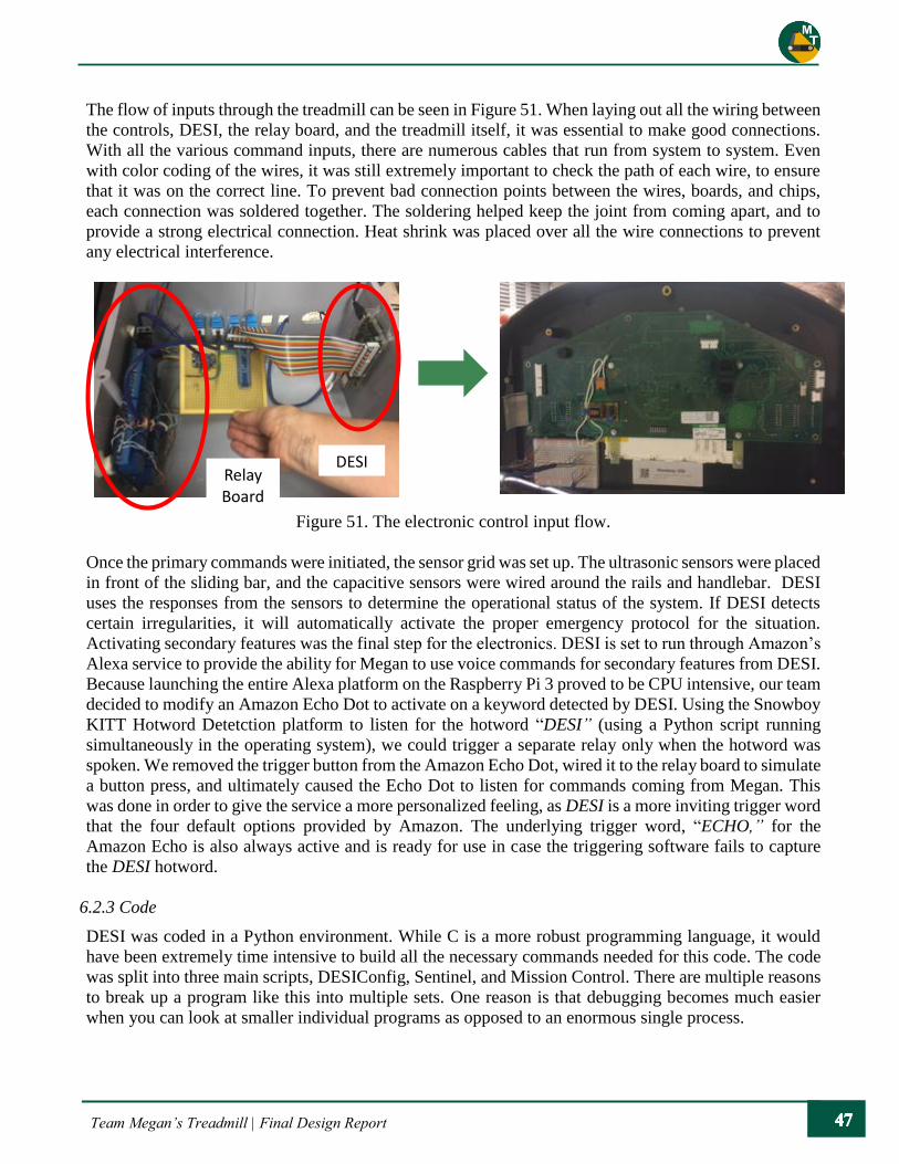
Team Megan’s Treadmill | Final Design Report
The flow of inputs through the treadmill can be seen in Figure 51. When laying out all the wiring between
the controls, DESI, the relay board, and the treadmill itself, it was essential to make good connections.
With all the various command inputs, there are numerous cables that run from system to system. Even
with color coding of the wires, it was still extremely important to check the path of each wire, to ensure
that it was on the correct line. To prevent bad connection points between the wires, boards, and chips,
each connection was soldered together. The soldering helped keep the joint from coming apart, and to
provide a strong electrical connection. Heat shrink was placed over all the wire connections to prevent
any electrical interference.
Figure 51. The electronic control input flow.
Once the primary commands were initiated, the sensor grid was set up. The ultrasonic sensors were placed
in front of the sliding bar, and the capacitive sensors were wired around the rails and handlebar. DESI
uses the responses from the sensors to determine the operational status of the system. If DESI detects
certain irregularities, it will automatically activate the proper emergency protocol for the situation.
Activating secondary features was the final step for the electronics. DESI is set to run through Amazon’s
Alexa service to provide the ability for Megan to use voice commands for secondary features from DESI.
Because launching the entire Alexa platform on the Raspberry Pi 3 proved to be CPU intensive, our team
decided to modify an Amazon Echo Dot to activate on a keyword detected by DESI. Using the Snowboy
KITT Hotword Detetction platform to listen for the hotword “DESI” (using a Python script running
simultaneously in the operating system), we could trigger a separate relay only when the hotword was
spoken. We removed the trigger button from the Amazon Echo Dot, wired it to the relay board to simulate
a button press, and ultimately caused the Echo Dot to listen for commands coming from Megan. This
was done in order to give the service a more personalized feeling, as DESI is a more inviting trigger word
that the four default options provided by Amazon. The underlying trigger word, “ECHO,” for the
Amazon Echo is also always active and is ready for use in case the triggering software fails to capture
the DESI hotword.
6.2.3 Code
DESI was coded in a Python environment. While C is a more robust programming language, it would
have been extremely time intensive to build all the necessary commands needed for this code. The code
was split into three main scripts, DESIConfig, Sentinel, and Mission Control. There are multiple reasons
to break up a program like this into multiple sets. One reason is that debugging becomes much easier
when you can look at smaller individual programs as opposed to an enormous single process.
Relay Board
DESI

Team Megan’s Treadmill | Final Design Report
DESI is the main program that has all the pin allocations and paths for the treadmill responses. This
basically acts as the translator between the control box, relay board, and Woodway computer. DESI also
regulates the feedback to Megan based on the inputs sent from the Raspberry Pi to the Woodway. The
relays are initiated based on the control input from the user. Sentinel’s main function is to check for any
errors while the treadmill is in operation. To help make the code robust, our team ensured that the
programming was structured in a multi-level system.
The highest tiers are protected by functions working at lower tiers. Drivers are imbedded in the system
to collect and store data from the sensor outputs, which are then routed to the higher-tiered programs.
Sentinel ensures that all the functions, running throughout the various programs, are operating in a proper
and efficient manner. For example, to stop multiple audio feedback responses from overlapping at the
same time, Sentinel utilizes a “mute speech” function.
Mission Control is another script that was created to help optimize the workload of the program. While
DESI maps out the commands and Sentinel checks the commands, Mission Control operates the system.
Mission Control is where the states for the dynamic sensor controls are located. The proximity and
capacitive sensor logic is all based in Mission Control. While all the code is critical in the operation of
the treadmill and DESI, Mission Control provides the direct link to the states of the treadmill based on
the inputs from the user and sensors. While DESIConfig, Sentinel, and Mission Control are the main
programs running within the system, there are other important, low-level functions that run through the
computers of the system.
As the creator and implementer of these computer and electrical systems, Eddie Ruano has much more
information on the technical details. Because this senior project was based in the mechanical engineering
department, much of the detail, including the code itself, was excluded.
7. Safety Considerations
Safety has been of the utmost concern during all stages of the design and manufacturing processes. The
safety concerns that are present in the system have been addressed, and the methods our team used to
mitigate these issues will be discussed. The safety hazard checklist discussed in chapter 4 was relevant
in making the safety decisions.
The first set of safety considerations involves Megan’s interaction with the treadmill. One of the primary
concerns is Megan’s ease of getting on and off the treadmill, so, in a previous design, a step was included
at the back of the treadmill. However, through testing with Megan, it was decided that the side rails were
sufficient support. The side rails reach past the end of the treadmill so Megan has support before she even
interacts with the actual treadmill. The biggest safety concern is Megan’s loss of balance while
exercising. To mitigate this risk, many safety measures were implemented: the main gripping system, the
full-length side rails, and the stop button. In the event Megan falls, the emergency stop procedure, induced
by information provided by the capacitive sensors, turns off the treadmill to prevent further injury. The
last safety concern is Megan’s transition from holding the main grips to holding the side rails, and vice
versa. As a part of Megan’s introduction to the treadmill system, she will be coached on the process of
transferring hand positions. As Megan becomes familiar with the system, this process will be second
nature for her.
The next set of considerations relates to the mechanical design. The first concern was the stability of the
side rails: they cannot deflect significantly from any force Megan could produce. The base feet mounted
to the plywood base provides a very stable base, and the T-slot was sized to take any loads Megan could

Team Megan’s Treadmill | Final Design Report
produce. Testing of this safety concern is discussed in the following chapter. Another area of concern is
the presence of pinch points due to the sliding rail assembly. Earlier designs contained compression
springs (located on the front side of the sliding rail) and speed reducers (located on the back side of the
sliding rail); since these components were eliminated, so were their pinch points. There is wiring running
to the control panel and the capacitive sensors, which Megan could potentially catch her hand on. To
mitigate this possibility, the wiring is run in sheathing and is tucked away in the grooves of the T-Slot as
much as possible.
The last set of safety considerations revolve around the electrical and computer systems. Loss of
feedback, providing incorrect feedback, and the full shutdown or failure of one of these systems are
concerns that need to be addressed. Our team has thoroughly tested any scenario that we could foresee
be encountered and have ensured that the electrical and computer systems operate correctly. As a final
precaution, we have implemented automatic shutdown protocols in the event a system does fail.
8. Testing
The controls, feedback, and support systems were all tested extensively to ensure that the treadmill
operates at peak performance and Megan’s workouts are safe and enjoyable. Each function had various
methods of testing.
Controls
The controls were tested for irregular triggering, which occurs when a change of state happens. Once this
was accomplished, we performed a stress test in which unlikely transitions and inputs were performed to
try and break the DESI listening software. Interference testing was then performed to assure that external
presses on the touchpad would not hamper our ability to communicate with the treadmill via the relay
board.
Feedback
The proximity sensors were tested and calibrated to ensure accurate data of Megan’s location is provided
to DESI. The capacitive sensors were tested in sections; each section was based on a different point of
contact independent of other points. The audible feedback of the included speaker was tested to ensure
that DESI’s response and the volume and power levels were appropriate.
Support
The stability and sturdiness of the rails were tested qualitatively by our team. Though not perfectly rigid,
the horizontal rails are able to support approximately 200 pounds at any point without a noticeable
deflection. The sliding arm was confirmed to have a range of motion of 10 inches.
Based on the specifications outlined in Section 3.2, a test plan was created to validate that the criteria are
satisfied by the final product. An outline of the plan can be seen in Table 11. Some of the test plans focus
on gathering quantitative datum while others focus on qualitative data. Qualitative data was taken for
more ergonomic features on the treadmill, like stabilization and time to learn. The test results, along with
the DVP&R can be seen in Appendix R. An important aspect of the time to learn specification is the
operator’s manual, which can be seen in Appendix S.

Team Megan’s Treadmill | Final Design Report
Table 11. Specification List for Testing
SPECIFICATION TEST PLAN
MAX SPEED
1. Take measurements of treadmill track length
2. Make a visible mark on one of the treads (bright foam pad)
3. Set treadmill to desired speed controls
4. Have 2 people recording time/how many passes the mark makes over
1-2 minutes.
5. Convert the distance covered over the speed to calculate an average
velocity
6. Compare to desired speed input
MAX
ACCELERATION
1. Confirm velocity settings
2. Have treadmill start from rest and go up to various speeds
3. Have user gauge how appropriate accelerations are set
- Team member does preliminary testing, then confirm with
Megan’s family
4. Modify the change in speed ratio to desired acceleration
MAX HEIGHT
1. Have rail posts bolted to wooden platform.
2. Adjust horizontal bars to user preference
3. Ensure clearance with existing treadmill structure
MAX FLOOR
AREA
1. Check final area so that treadmill safely fit on the plywood base area,
and the plywood base would fit in the final location for the treadmill.
USER
STABILIZATION
1. Identify all joints in system
2. Apply approximately 200 pounds to worst case loading areas
3. Check for deflections (linear and angular)
4. Look for any high sources of stress concentrations
5. Perform a torque check on fasteners to ensure they are fully tightened
down
VOLTAGE INPUT
1. Identify all sources of voltage input within system
2. Use voltmeter to determine the largest voltage areas
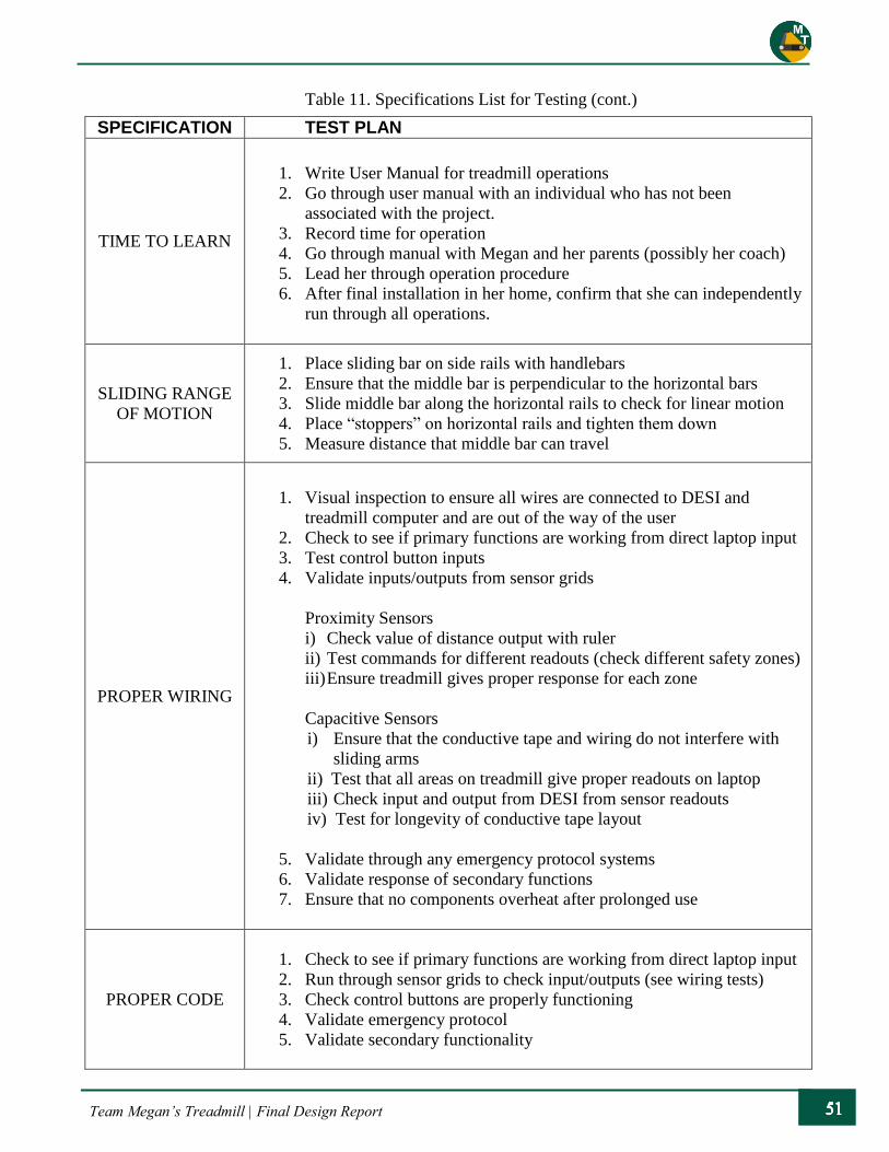
Team Megan’s Treadmill | Final Design Report
Table 11. Specifications List for Testing (cont.)
SPECIFICATION TEST PLAN
TIME TO LEARN
1. Write User Manual for treadmill operations
2. Go through user manual with an individual who has not been
associated with the project.
3. Record time for operation
4. Go through manual with Megan and her parents (possibly her coach)
5. Lead her through operation procedure
6. After final installation in her home, confirm that she can independently
run through all operations.
SLIDING RANGE
OF MOTION
1. Place sliding bar on side rails with handlebars
2. Ensure that the middle bar is perpendicular to the horizontal bars
3. Slide middle bar along the horizontal rails to check for linear motion
4. Place “stoppers” on horizontal rails and tighten them down
5. Measure distance that middle bar can travel
PROPER WIRING
1. Visual inspection to ensure all wires are connected to DESI and
treadmill computer and are out of the way of the user
2. Check to see if primary functions are working from direct laptop input
3. Test control button inputs
4. Validate inputs/outputs from sensor grids
Proximity Sensors
i) Check value of distance output with ruler
ii) Test commands for different readouts (check different safety zones)
iii) Ensure treadmill gives proper response for each zone
Capacitive Sensors
i) Ensure that the conductive tape and wiring do not interfere with
sliding arms
ii) Test that all areas on treadmill give proper readouts on laptop
iii) Check input and output from DESI from sensor readouts
iv) Test for longevity of conductive tape layout
5. Validate through any emergency protocol systems
6. Validate response of secondary functions
7. Ensure that no components overheat after prolonged use
PROPER CODE
1. Check to see if primary functions are working from direct laptop input
2. Run through sensor grids to check input/outputs (see wiring tests)
3. Check control buttons are properly functioning
4. Validate emergency protocol
5. Validate secondary functionality

Team Megan’s Treadmill | Final Design Report
The first phase of testing evaluated the basic functions and overall quality of the design. Our team
analyzed the accessibility and ergonomics of the process of entering and exiting the treadmill. The
responses to input commands and the audio feedback system were monitored in this phase to ensure they
functioned for every possible scenario. The second phase of testing included assessment of the motion of
the horizontal rail. Our team monitored and evaluated DESI’s response to the linear motion of the rail to
ensure the response was appropriate.
When developing the proper software and algorithms for our DESI controller, we adopted the
Incremental Build & Test philosophy which advised small implementations followed by rigorous testing.
Large programming builds such as this one require multiple layers of abstraction and algorithm
development; therefore, it was in our best interest to build from the lowest level of software to higher-
level language implementations.
The lower level code that communicates with each sensor from the sensor array is written in a with
debugging fashion, in which print data and error failure codes, mapped to each individual failure point,
are left in the final compile. Usually when launching a firmware, the debugging information is removed
to improve the speed and size of the system and the file system footprint; however, such debugging trace
calls posed no serious speed reduction for DESI.
Upper level error handling is a more structured protocol regarding the chaining of actions implemented
when a specific error happens. While in low level error handling, the error is simply passed up the data
flow chain, upper level error handlers must identify the error and act accordingly. If we deemed the error
of great importance or hindrance to the safe operation of the treadmill, it was immediately sent to the
Emergency State until fixed.
9. Cost Analysis
This project received funding for $1000.00 through the CP Connect Fund at Cal Poly. The CP Connect
Fund’s goal is to “create opportunities for donors, faculty and students to collaborate on interdisciplinary
educational projects by facilitating access to: potential projects, resources, relevant information,
connections with corporate partners, and the interdisciplinary community of Cal Poly.”6 While cost
played a large factor when choosing components, the first concern was quality. Since this product is
going into full use at Megan’s home, it was critical that we did not cut corners on components unless the
alternative product provided equal or improved quality. The bill of materials, shown in Appendices T
and U, is broken into mechanical and electrical component sections to help maintain the original budget.
The mechanical components in the controller assembly played a minor part of the budget; however, they
were critical in the overall design. The buttons, switch, and control box are stock parts that were
purchased through Amazon. Our team also had access to a personal 3-D printer off-campus which was
used to prototype and manufacture certain parts, such as the proximity sensor mounts. The road bike
handlebars were bought second-hand at a discounted rate.
All the rails were made of T-Slot, which is more expensive than general structural steel tubing. We used
T-Slot because it provided acceptable material qualities and a superior fastening method allowing for
adjustments throughout the build. The total length of T-Slot needed for the side rails and middle bar was
approximately 400” (33’). At $0.53 an inch, the T-Slot cost was a significant part of the budget. The
other significant costs came from the linear bearings, used for the sliding arm. Fortunately, multiple
distributors offer student discounts, which greatly reduced the price7. The rail system is a critical part of
the overall focus to keep Megan both safe and independent while operating the treadmill, which is why
Team Megan’s Treadmill | Final Design Report
we allowed it to absorb a significant portion of the budget. Stock parts were chosen to save money, ease
the manufacturing process, and allow for easier repair, if necessary.
The tactile feedback was a small portion of the budget. There are 60 treads on the Woodway treadmill,
so a total of 60 bumpers were used. A total of 80 bumpers were ordered, so there are extra in the event
some of them fall off. This design’s ability to be repaired, or replaced, is cost effective and robust.
Appendix T shows the bill of materials for the mechanical systems.
The electronic systems components are broken into three categories: the control unit, the sensor grid, and
the feedback module. A breakdown of costs for the electrical components can be seen in Appendix U.
The three “big ticket” items are the Raspberry Pi 3 Module, the Raspberry Pi camera, and the microphone.
Another key component was the Amazon Echo, which provided the secondary voice control features. All
the electrical components can be found through Amazon and Adafruit. Some of the materials, including
wire and soldering materials are included as initial estimates for cost and may be adjusted for the final
product.
The cost estimate from the critical design phase was approximately $600, which was an underestimate
of the actual cost of the project. There were multiple costs that proved necessary after entering the
manufacturing phase. The main costs came from adding stability to the rails with new base feet and extra
cross bars of aluminum T-Slot. Other miscellaneous costs for the mechanical systems included a plywood
base, paint for the wood, clamps for the handlebars, and a few other smaller items used for prototyping
and testing. The actual overall cost of the project was approximately $980 which was still within the
$1000.00 CP Connect fund.
10. Maintenance and Repair Considerations
A new Woodway Desmo treadmill warranty lasts ten years for the frame, five years for the drive, motor,
and belt, and three years for the rest of the components. Since the treadmill was donated by Cal Poly’s
Recreation Center, the warranty from Woodway has been voided, but it did go through a full-service
inspection by from a Woodway-certified technician, Roberto Espinosa. He checked the treadmill to
ensure it was properly working before releasing it to our group for the project. Roberto has been an
extremely helpful resource for information about the maintenance and internal workings of the treadmill
and has provided guidance of how to integrate our new system with the treadmill. We have performed a
full inspection of the treadmill and additional systems during the Hardware Testing Review as well as
before delivering it to Megan’s home.
A full user and maintenance manual for the new components has been provided to Megan and her family
to assist them with operations. This includes the operating procedure for the treadmill and any required
maintenance for the system. Woodway’s maintenance manual and user guide for the Desmo treadmill
has also be provided to Megan’s family.
As discussed in the cost analysis, stock parts were chosen to save money, ease the manufacturing process,
and allow for simple repairs in the future. The only custom parts designed for this project are the holes
in the junction box and the proximity sensor cases. It is very unlikely that these components will fail;
however, if they do, the engineering drawings for the components will be included in the repair
guidelines. This will allow for an inexpensive replacement for any damaged components.

Team Megan’s Treadmill | Final Design Report
11. Management Plan
The project was a full team collaboration; however, each team member managed certain subsystems for
the duration of the project. The titles and responsibilities for each team member were subject to change
as the year progressed and the project evolved. These leadership roles were critical to ensure an even
division of labor as well as optimal efficiency throughout the project.
Eddie Ruano - Research & Electronics System Lead Eddie was the lone computer engineer of the team and had experience in programming and electronic
component design. The research lead was responsible for compiling any research that was collected
throughout this project. The role of electronics system lead involved heading up design and procurement
of any electronic systems throughout the project as well as overviewing the necessary computer
programming.
Daniel Byrne - Controller Design & Communications Lead The controller design lead oversaw the development of the interface between the user and the treadmill
system, including the points of contact and control inputs. This position also included the responsibility
of ensuring the final product was accessible and ergonomic for the user. The communications lead
oversaw communicating with the sponsor, the client, and any external sources related to the project.
Michael Peck – Rail System Design & Project Management Lead The rail system design lead oversaw the development of the support system that directly provides a safe
workout environment. This position also supervised the computer modeling and bill of materials of the
system and overall progress of manufacturing. The project manager’s role was to track the progress of
the team throughout the year as well as keep track of funds for the project.
Our team was held to certain deadlines for the project. This project started with ideation and ended with
testing of the final manufactured product; by the end of Spring Quarter the project was complete. Table
12 displays an outline of critical dates and milestones for the project.
Table 12. Project milestone timeline
Milestone Data
Project Proposal October 25, 2016
Preliminary Design Review November 15, 2016
Critical Design Review February 7, 2017
Manufacturing and Test Review March 16, 2017
Senior Project Expo June 2, 2017
A more detailed breakdown of our team’s design process for the year can be found in Appendix V. The
Gantt chart summarizes all the phases of this project, from ideation through testing. Our team used this
schedule as a reference of time frame for the project to help stay on track.

Team Megan’s Treadmill | Final Design Report
12. Conclusion
Our team’s final system fulfills all the criteria specified during the preliminary stages of this project, and
we believe it achieves the goal of providing Megan with a safe and independent workout environment.
One of the interesting aspects of this project is the integration of both mechanical and electrical
components into a cohesive, independent system. The final product contains both this new system and
the original Woodway treadmill, creating a brand-new workout experience.
Due to constraints on time and resources, some compromises were made throughout the timeline of this
project, but our team is very proud of the final product we developed through Senior Project. When
looking back at the preliminary design, it is remarkable how much the design has evolved. Throughout
the process, many challenges arose; however, our team met those challenges head on. Senior Project has
truly been a culminating educational experience to our college career. We hope that this treadmill system
and DESI can help Megan enjoy her workouts and continue to have a happy and healthy lifestyle!
Team Megan’s Treadmill | Final Design Report
13. Works Cited
1 Bartlo, Pamela, and Penelope J. Klein. “Physical Activity Benefits and Needs in Adults with
Intellectual Disabilities: Systematic Review of the Literature.” American Journal on Intellectual
and Developmental Disabilities 116.3 (2011): 220-32. Web. 2 Cybex Total Access Treadmill. Cybex Research Institute. http://www.cybexintl.com/total-access-
treadmill.aspx Accessed 24 October 2016. 3 LiteGait Treadmills. LiteGait Rehab Solutions. http://litegait.com/products/treadmills. Accessed 24
October 2016. 4 Accessible Pedestrian Signals, A Guide to Best Practices, "Understanding how Blind Pedestrians
Cross at Signalized Intersections." http://apsguide.org/appendix_d_understanding.cfm. Accessed
17 November 2016. 5. Ease of Use Assistant, Georgia Tech Research Institute, “Hand Anthropometry.
http://usability.gtri.gatech.edu/eou_info/hand_anthro.php. Accessed 8 February 17. 6. Cal Poly College of Engineering. CP Connect, https://cpconnect.calpoly.edu/ Accessed 8 February
17. 7. Tslots, By Futura Industries, T-Slotted Aluminum Extrusion, http://www.tslots.com/. Accessed 8
February 17.
Team Megan’s Treadmill | Final Design Report
14. Appendices
Appendix A: Woodway Treadmill – Desmo Product Information
Appendix B: Quality Function Deployment
Appendix C: Pugh Matrix for Overall System
Appendix D: Decision Flowchart for Megan’s Family and Michael Lara
Appendix E: Safety Hazard Checklist
Appendix F: Raspberry Pi 3 Specifications
Appendix G: Computational Data Flow Chart
Appendix H: Megan’s Traced Handprint with Measurements
Appendix I: T-Slots Vendor Loading Data for Railing
Appendix J: Exploded Assembly of Rail System from CDR
Appendix K: 2-D Drawings for Stopper
Appendix L: Product Description Sheet - Proximity & Capacitive Sensors
Appendix M: 2-D Drawing for Proximity Sensor Case
Appendix N: Product Description Sheet – Button and Rotary Switch
Appendix O: Product Description Sheet –Bumpers
Appendix P: 3-D Assembly Drawings for Final System
Appendix Q: Product Description Sheet – T-Slot Components
Appendix R: Test Results & DVP&R
Appendix S: Operator’s Manual
Appendix T: Bill of Materials for Mechanical Systems
Appendix U: Bill of Materials for Electrical Systems
Appendix V: Full Year Gantt Chart

Team Megan’s Treadmill | Final Design Report
Appendix A: Woodway Treadmill - Desmo Product Information

Team Megan’s Treadmill | Final Design Report
Appendix B: Quality Function Deployment

Team Megan’s Treadmill | Final Design Report
Appendix C: Pugh Matrix for Overall System
Pugh Matrix – System Level
Solution Alternatives
Key Criteria Import
ance
Rat
ing
Ori
gin
al T
read
mil
l
Pri
mar
y
Red
undan
t
Sec
ondar
y
Accessible/Effective Controls 5 + - S
Accessible/Effective Feedback 5 + + +
Freedom of Movement 2 S + S
Simplicity to Design/Build/Test 4 S - +
Time to Learn 1 + - S
Ergonomics 4 + + S
Ease of Use (Independence) 3 + S +
Level of Safety 5 S + -
Versatility/Adaptability 1 - - -
Sum of Positives 5 4 3
Sum of Negatives 1 4 2
Sum of Sames 3 1 4
Weighted Sum of Positives 18 16 12
Weighted Sum of Negatives 0 10 5
TOTALS 18 6 7
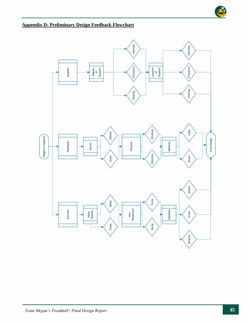
Team Megan’s Treadmill | Final Design Report
Appendix D: Preliminary Design Feedback Flowchart

Team Megan’s Treadmill | Final Design Report
Appendix E1: Safety Hazard Checklist
MEGAN’S TREADMILL Sarah Harding
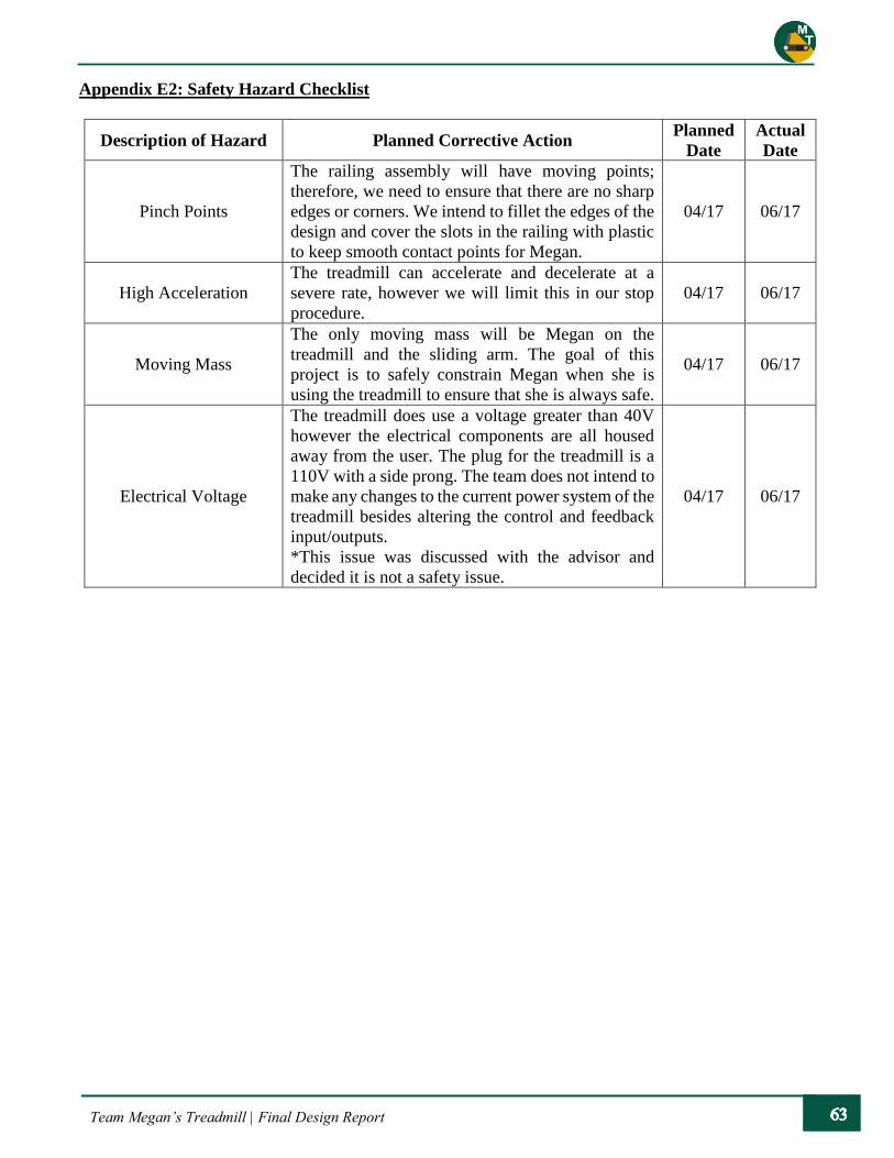
Team Megan’s Treadmill | Final Design Report
Appendix E2: Safety Hazard Checklist
Description of Hazard Planned Corrective Action Planned
Date
Actual
Date
Pinch Points
The railing assembly will have moving points;
therefore, we need to ensure that there are no sharp
edges or corners. We intend to fillet the edges of the
design and cover the slots in the railing with plastic
to keep smooth contact points for Megan.
04/17 06/17
High Acceleration
The treadmill can accelerate and decelerate at a
severe rate, however we will limit this in our stop
procedure.
04/17 06/17
Moving Mass
The only moving mass will be Megan on the
treadmill and the sliding arm. The goal of this
project is to safely constrain Megan when she is
using the treadmill to ensure that she is always safe.
04/17 06/17
Electrical Voltage
The treadmill does use a voltage greater than 40V
however the electrical components are all housed
away from the user. The plug for the treadmill is a
110V with a side prong. The team does not intend to
make any changes to the current power system of the
treadmill besides altering the control and feedback
input/outputs.
*This issue was discussed with the advisor and
decided it is not a safety issue.
04/17 06/17

Team Megan’s Treadmill | Final Design Report
Appendix F: Raspberry Pi 3 Specifications

Team Megan’s Treadmill | Final Design Report
Appendix G: Computational Data Flow Chart

Team Megan’s Treadmill | Final Design Report
Appendix H: Megan’s Traced Handprint with Measurements

Team Megan’s Treadmill | Final Design Report
Appendix I: TSLOTS Vendor Loading Data for Railing
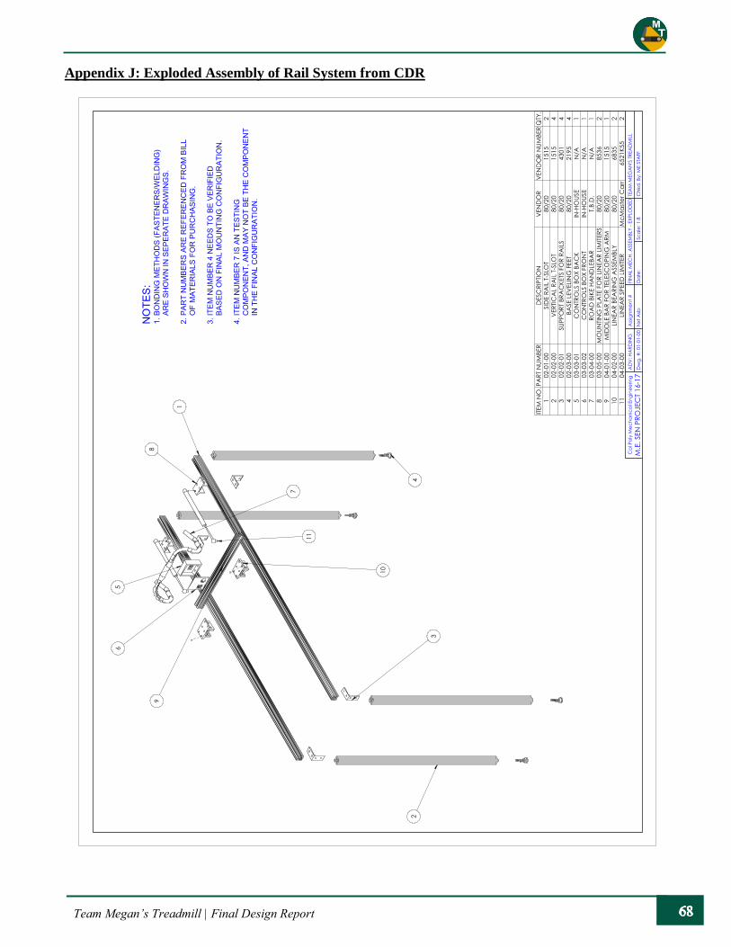
Team Megan’s Treadmill | Final Design Report
Appendix J: Exploded Assembly of Rail System from CDR
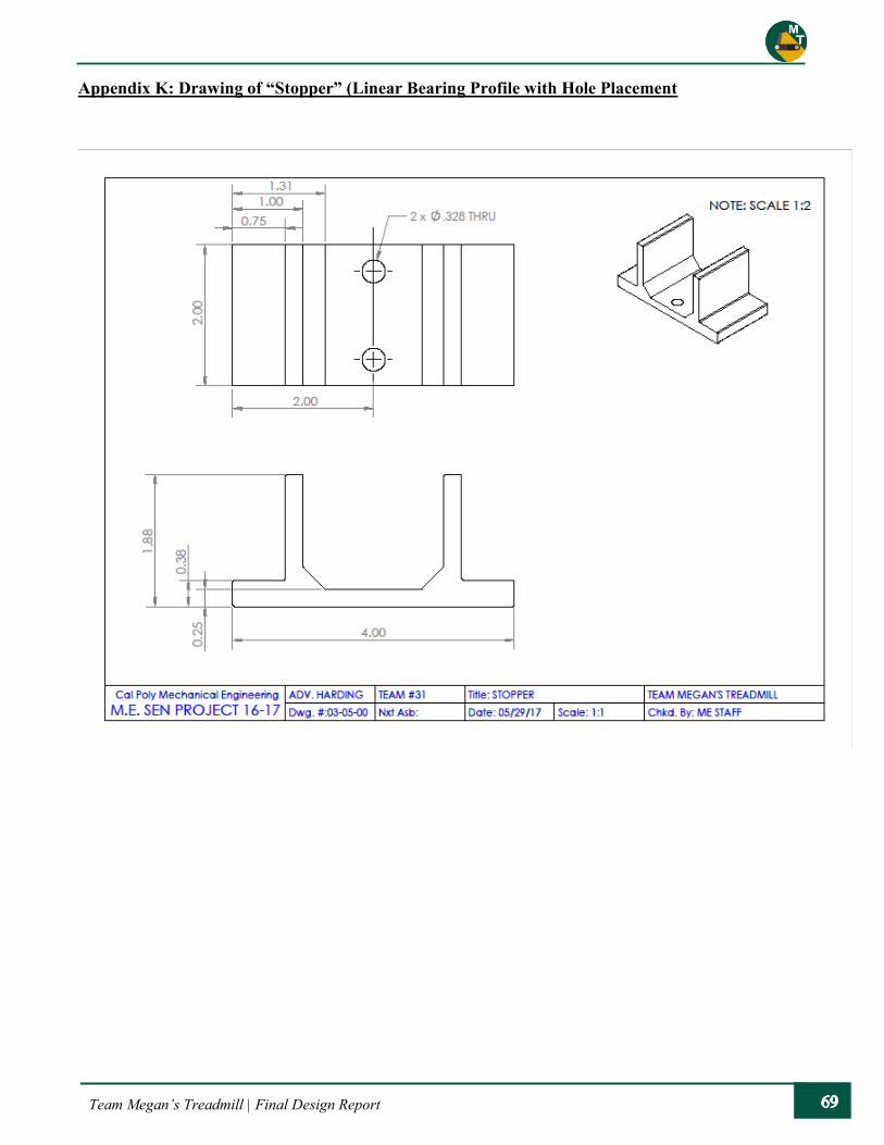
Team Megan’s Treadmill | Final Design Report
Appendix K: Drawing of “Stopper” (Linear Bearing Profile with Hole Placement

Team Megan’s Treadmill | Final Design Report
Appendix L1: Product Data Sheet for Proximity Sensor (1)
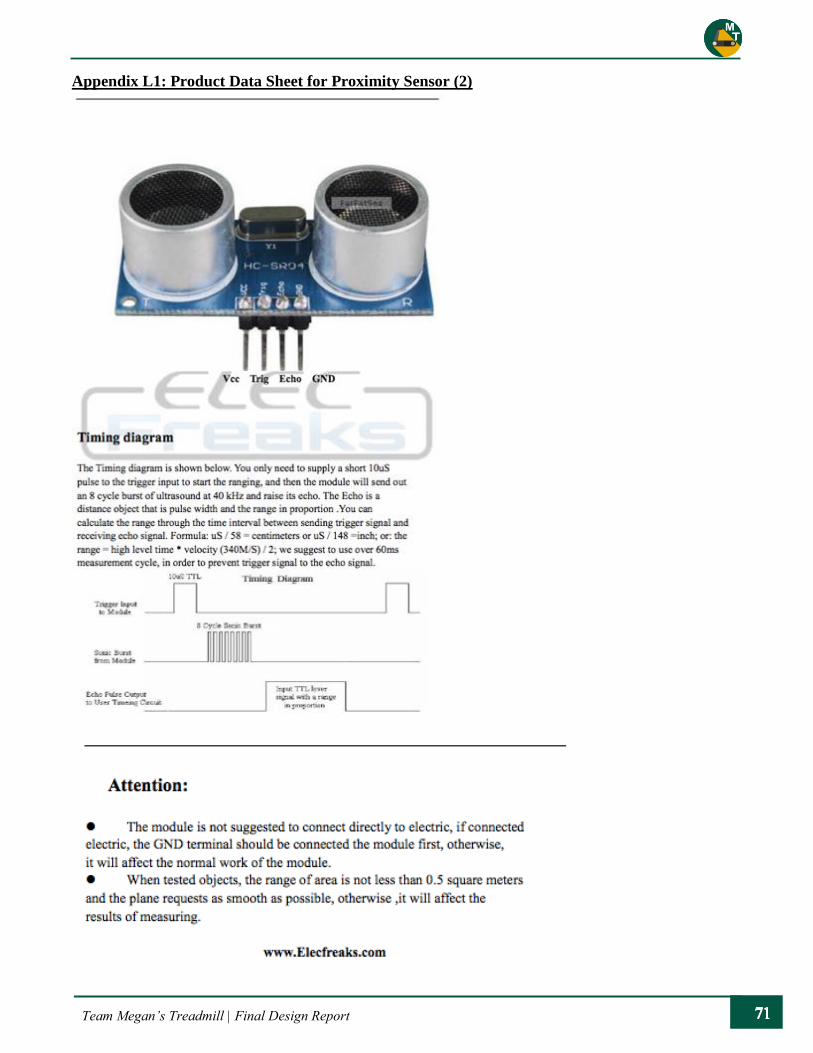
Team Megan’s Treadmill | Final Design Report
Appendix L1: Product Data Sheet for Proximity Sensor (2)

Team Megan’s Treadmill | Final Design Report
Appendix L2: Product Data Sheet for Capacitive Sensor
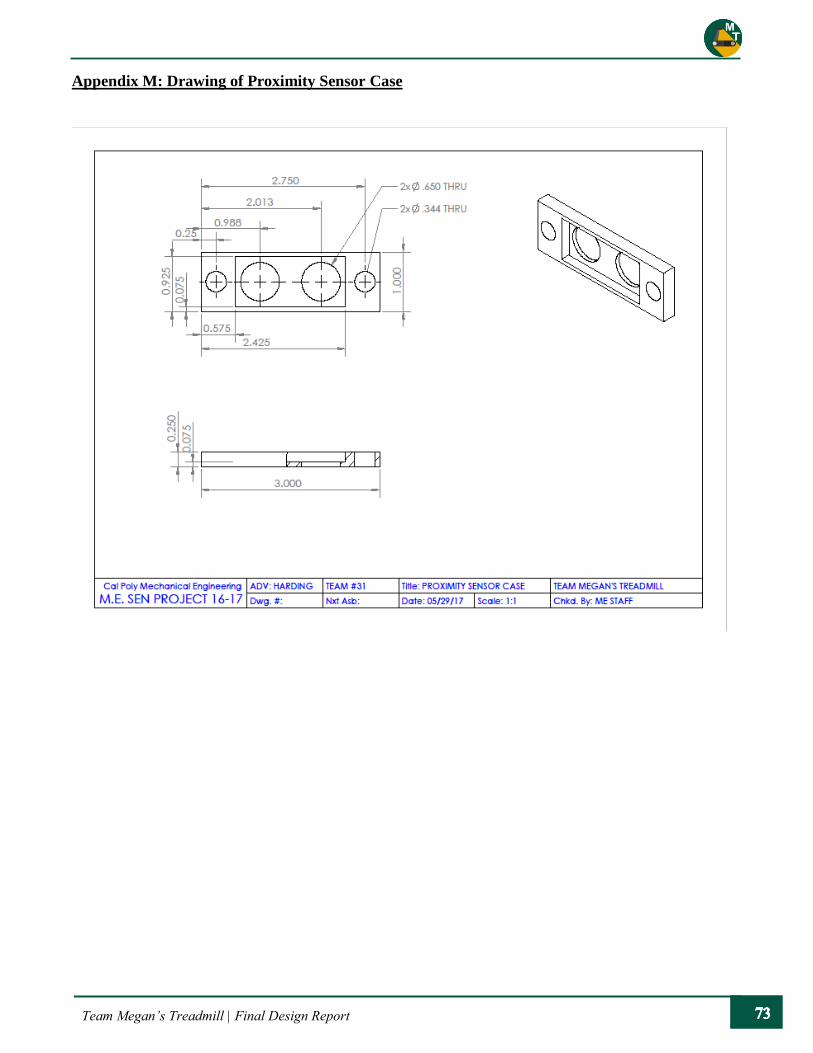
Team Megan’s Treadmill | Final Design Report
Appendix M: Drawing of Proximity Sensor Case
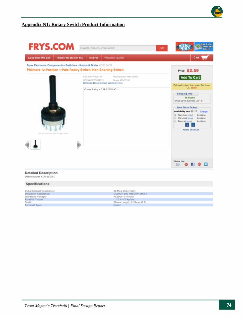
Team Megan’s Treadmill | Final Design Report
Appendix N1: Rotary Switch Product Information

Team Megan’s Treadmill | Final Design Report
Appendix N2: Electronic Button for Control Panel – Product Information
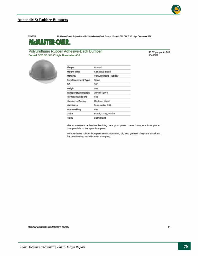
Team Megan’s Treadmill | Final Design Report
Appendix S: Rubber Bumpers

Team Megan’s Treadmill | Final Design Report
Appendix P: Assembly of Final Rail System

Team Megan’s Treadmill | Final Design Report
Appendix Q1: Drawing of Base Feet
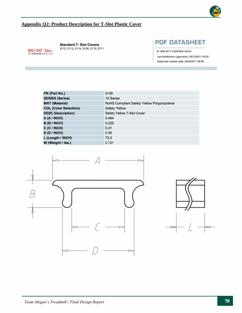
Team Megan’s Treadmill | Final Design Report
Appendix Q2: Product Description for T-Slot Plastic Cover
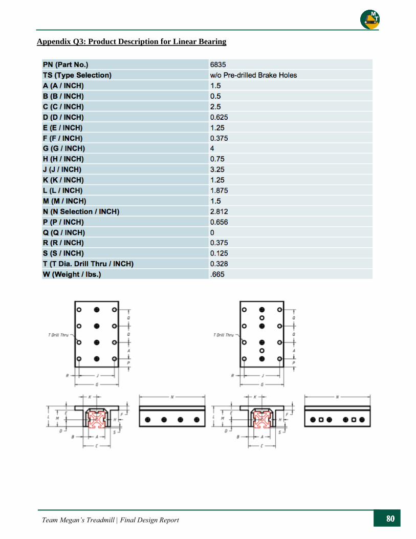
Team Megan’s Treadmill | Final Design Report
Appendix Q3: Product Description for Linear Bearing
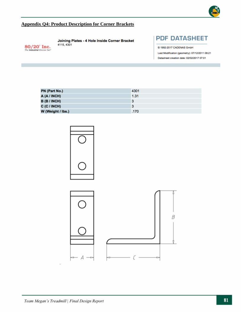
Team Megan’s Treadmill | Final Design Report
Appendix Q4: Product Description for Corner Brackets
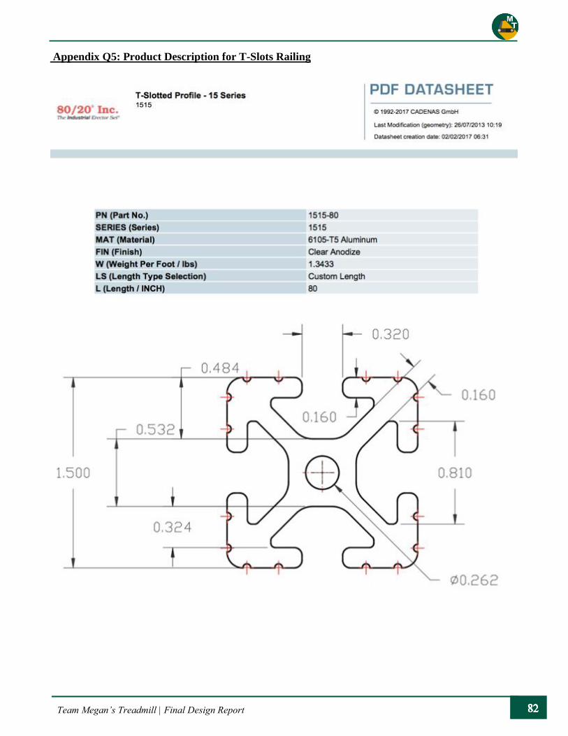
Team Megan’s Treadmill | Final Design Report
Appendix Q5: Product Description for T-Slots Railing

Team Megan’s Treadmill | Final Design Report
Appendix Q6: Double T-Slot Extrusion
NUMBERPART
Information in this drawing is provided for reference only.
http://www.mcmaster.com
3"
1 1/2" 0.262"
0.32"
0.16"
1.5"0.75"
0.81" 2 ft.
47065T109Aluminum
T-Slotted Framing© 2015 McMaster-Carr Supply Company
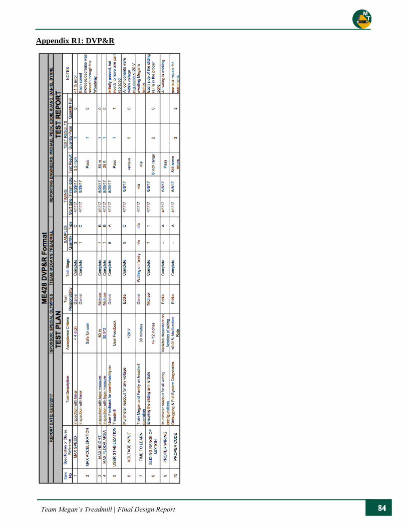
Team Megan’s Treadmill | Final Design Report
Appendix R1: DVP&R

Team Megan’s Treadmill | Final Design Report
Appendix R2: TEST SHEET – MAX SPEED
GOAL: To determine the maximum speed that the treadmill will reach with
DESI’S Control System
DATE: 6/8/17
PARTICIPANTS: Daniel Byrne, Michael Peck, Eddie Ruano
Equipment: iPhone Timer
STEPS: 1. Take measurements of treadmill track length:
21in/9 treads * 60 treads = 140”
2. Make a visible mark on one of the treads (bright foam pad)
3. Set treadmill to maximum speed setting – 3.5 mph = 61.60 in/min
4. Have 2 people recording time/how many passes the mark makes over approximately 1 minute,
three times.
Time of test interval Number of passes Comments
TEST
1
Recorder 1 58.97 seconds 26.0
Recorder 2 59.15 seconds 26.0
TEST
2
Recorder 1 60.34 seconds 26.5
Recorder 2 59.45 seconds 26.5
TEST
3
Recorder 1 61.21 seconds 26.0
Recorder 2 60.45 seconds 27.0
AVERAGES: 59.93 seconds 26.3
5. Use the number of passes, length of track, and time of the test interval to calculate an average
velocity:
Velocity = Number of Passes * Length of Track / Time of Test Interval
Velocity = (26.3 passes) * (140 in/pass) / (59.93 seconds) = 61.52 in/s
6. Compare to desired speed input:
% DIFFERENCE = (DESIRED VALUE – ACTUAL VALUE) / DESIRED VALUE * 100%
% DIFFERENCE = (61.60 – 61.52) / 61.60 *100 = 0.137 % error

Team Megan’s Treadmill | Final Design Report
Appendix R3: TEST SHEET – MAX ACCELERATION
GOAL: To determine the maximum acceleration that the treadmill will reach
with DESI’S Control System
DATE: 6/8/17
PARTICIPANTS: Daniel Byrne, Michael Peck, Eddie Ruano
Equipment: Control System
STEPS: 1. Confirm Velocity Settings
2. Outline possible speed changes
There are 5 speed settings (0 being off, 4 being maximum)
3. Go through extreme speed changes to get a qualitative reaction to the acceleration between
speeds.
Observations
Speed 0 -> 1
This sets the treadmill to 2.0 mph. The treadmill takes about a second to
start speeding up. It gets to 2.0 mph in a comfortable time.
Speed 1 -> 2
Very smooth transition between neighboring speeds when speeding up
Speed 0 -> 4
Speed 4 is 3.5 mph. The increase in speed is quick, but there is a decent
lead in time to allow the user to catch up to the main speed.
Speed 1 -> 0
The pause from 2.0 mph to 0 is not abrupt. It takes about 1.5 second
from hitting the pause button to coming to a complete stop.
Speed 2 -> 1
Very smooth transition between neighboring speeds when slowing down
Speed 4 -> 0
It takes approximately 2 seconds from hitting the pause button to being
at a complete stop. This motion feels very reasonable.
4. Adjust accelerations based on user reaction
- Typical treadmill accelerations were acceptable.
- Megan’s family was comfortable with current treadmill transitions, and we did not interfere
with any of the accelerations.
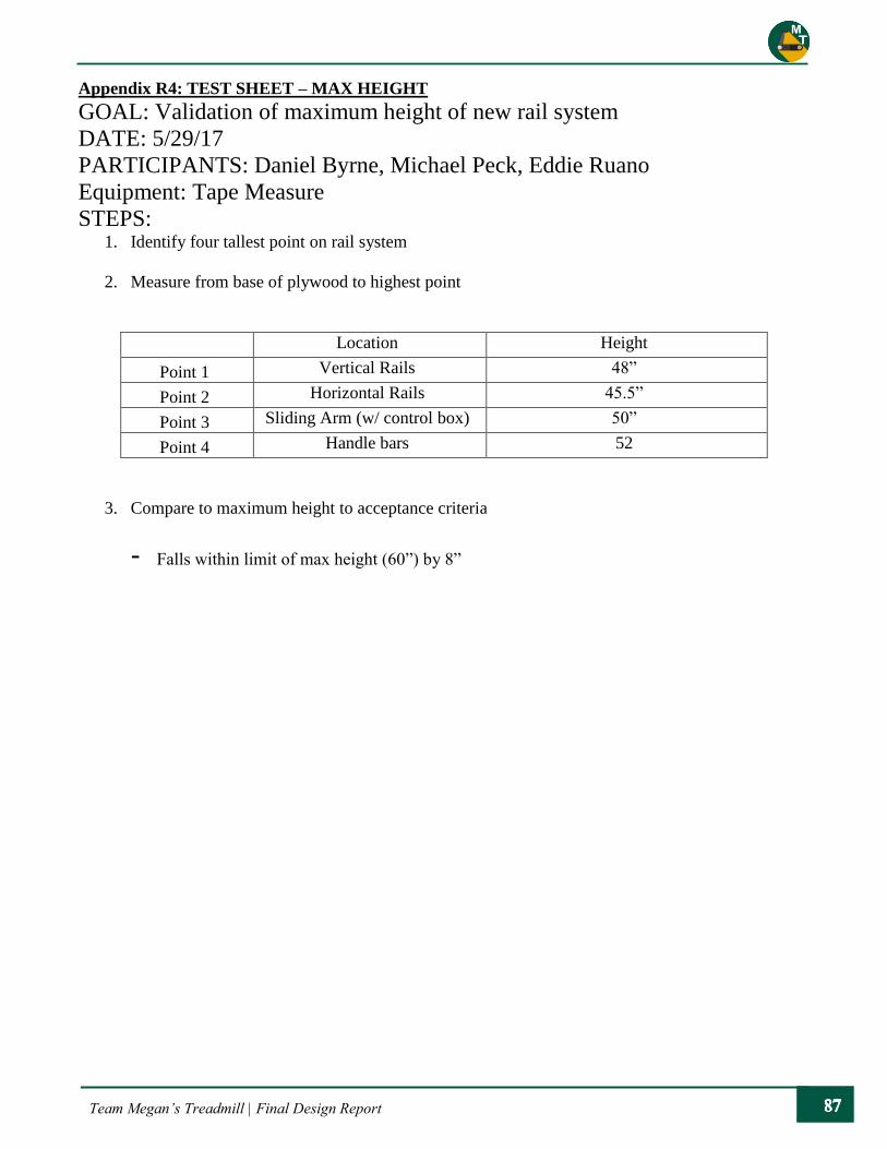
Team Megan’s Treadmill | Final Design Report
Appendix R4: TEST SHEET – MAX HEIGHT
GOAL: Validation of maximum height of new rail system
DATE: 5/29/17
PARTICIPANTS: Daniel Byrne, Michael Peck, Eddie Ruano
Equipment: Tape Measure
STEPS: 1. Identify four tallest point on rail system
2. Measure from base of plywood to highest point
Location Height
Point 1 Vertical Rails 48”
Point 2 Horizontal Rails 45.5”
Point 3 Sliding Arm (w/ control box) 50”
Point 4 Handle bars 52
3. Compare to maximum height to acceptance criteria
- Falls within limit of max height (60”) by 8”

Team Megan’s Treadmill | Final Design Report
Appendix R5: TEST SHEET – MAX FLOOR AREA
GOAL: Validation of maximum floor area of entire system
DATE: 5/29/17
PARTICIPANTS: Daniel Byrne, Michael Peck, Eddie Ruano
Equipment: Tape Measure
STEPS: 1. Identify maximum dimensions
2. Measure sides of plywood
Location Length
Side 1 Bottom 48”
Side 2 Left 90”
Side 3 Top 48”
Side 4 Right 90”
3. Calculate Floor Area
Area = Max Length 1 * Max Length 2
= 48” x 96” = 4320 in^2 = 30 ft^2
4. Compare to acceptance criteria
Exactly equal to criteria
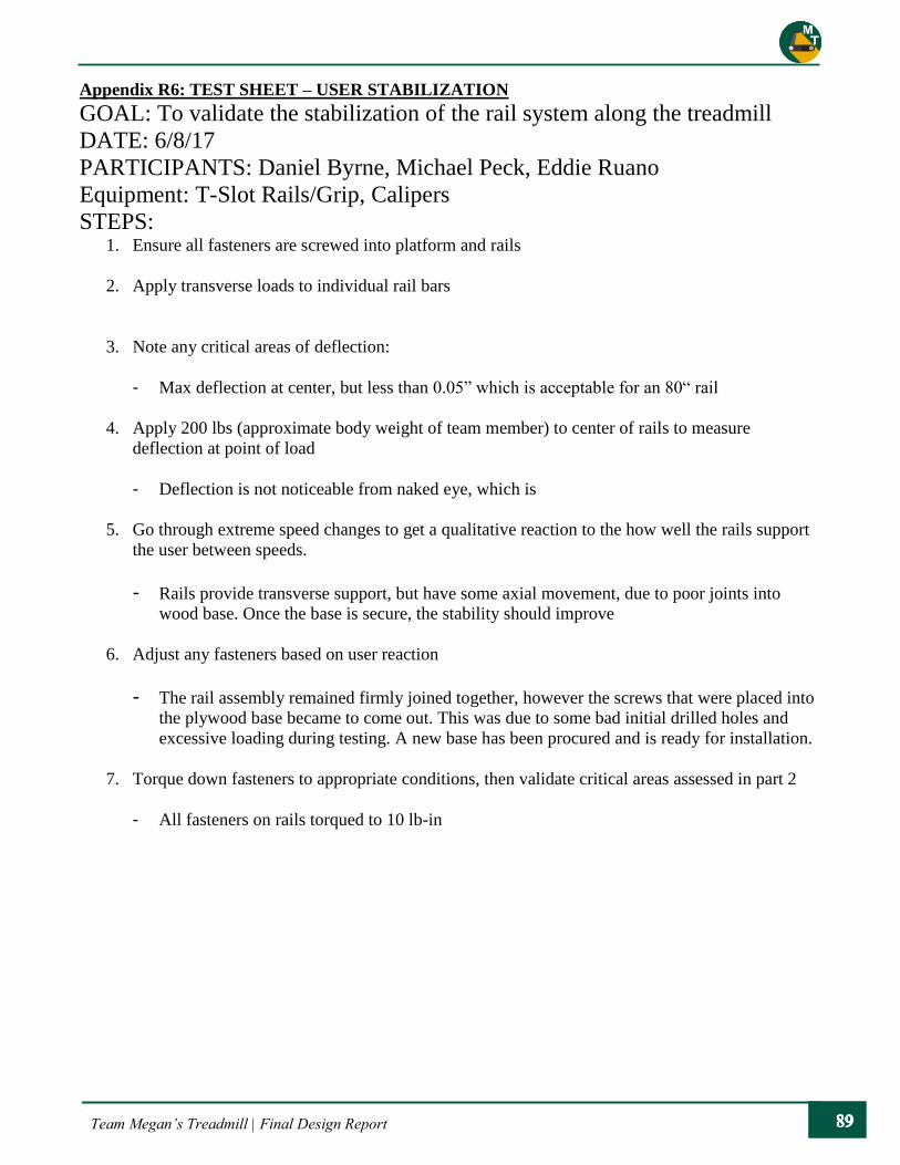
Team Megan’s Treadmill | Final Design Report
Appendix R6: TEST SHEET – USER STABILIZATION
GOAL: To validate the stabilization of the rail system along the treadmill
DATE: 6/8/17
PARTICIPANTS: Daniel Byrne, Michael Peck, Eddie Ruano
Equipment: T-Slot Rails/Grip, Calipers
STEPS: 1. Ensure all fasteners are screwed into platform and rails
2. Apply transverse loads to individual rail bars
3. Note any critical areas of deflection:
- Max deflection at center, but less than 0.05” which is acceptable for an 80“ rail
4. Apply 200 lbs (approximate body weight of team member) to center of rails to measure
deflection at point of load
- Deflection is not noticeable from naked eye, which is
5. Go through extreme speed changes to get a qualitative reaction to the how well the rails support
the user between speeds.
- Rails provide transverse support, but have some axial movement, due to poor joints into
wood base. Once the base is secure, the stability should improve
6. Adjust any fasteners based on user reaction
- The rail assembly remained firmly joined together, however the screws that were placed into
the plywood base became to come out. This was due to some bad initial drilled holes and
excessive loading during testing. A new base has been procured and is ready for installation.
7. Torque down fasteners to appropriate conditions, then validate critical areas assessed in part 2
- All fasteners on rails torqued to 10 lb-in

Team Megan’s Treadmill | Final Design Report
Appendix R7: TEST SHEET – VOLTAGE INPUT
GOAL: Ensure that voltage levels are at proper readings in critical
components of the treadmill/DESI
DATE: 6/8/17
PARTICIPANTS: Daniel Byrne, Michael Peck, Eddie Ruano
Equipment: Multi-meter
STEPS: 1. Isolate critical voltage areas
2. Measure voltage readings at the critical areas for various load conditions
Area Voltage Reading Allowable Voltage
Power Supply 110 V (AC) 110 V (AC)
Raspberry Pi 5 V (DC) 5V
Relay Board 12 V (DC) 12 V
Speaker 5 V (DC) 5 V (DC)
Woodway Board 16 V (DC) 16 V (DC)
3. Compare max readings to acceptance criteria
- All zones pass acceptance criteria

Team Megan’s Treadmill | Final Design Report
Appendix R8: TEST SHEET – TIME TO LEARN
GOAL: To make sure that the components in the system are intuitive, the time
it takes for Megan and her family to learn the operation of the
treadmill will be assessed
DATE: 6/8/17
PARTICIPANTS: Daniel Byrne, Michael Peck, Eddie Ruano
Equipment: Timer, User’s Manual
STEPS: 1. Bring in someone who hasn’t been involved with the project
2. Run them through the treadmill operations to see how long it takes for them to operate all
treadmill functions on their own
TIME: 30 minutes
3. Introduce Megan and her family to the treadmill and DESI
4. Allow them to look through the User’s Manual
5. Assist Megan with the physical characteristics of the treadmill
6. Demonstrate the functionality of the treadmill
7. Have the family try to operate the treadmill with our help
8. Have the family operate the treadmill with no assistance from the team
- This will happen upon delivery of the treadmill
TOTAL TIME: TBD

Team Megan’s Treadmill | Final Design Report
Appendix R9: TEST SHEET – SLIDING RANGE OF MOTION
GOAL: Validation of the sliding arm of the rail system
DATE: 6/8/17
PARTICIPANTS: Daniel Byrne, Michael Peck, Eddie Ruano
Equipment: Tape Measure
STEPS: 1. Install slider “stoppers”
2. Measure distance between the centerline of each pair of “stoppers” on each rail:
- 8”
3. Measure distance from front of treadmill to the fully extended sliding arm:
- 25”
4. Compare distances to acceptance criteria - Pass
5. Go through extreme speed changes to get a qualitative reaction to the how well the rails support
the user between speeds.
- Sliding rail holds up for all speeds in ranage
6. Make any adjustments and note changes to fasteners on sliding arm or horizontal rails to ease
sliding motion
- Once the handlebar was adjusted to the front of the sliding rail, the linear motion has been
relatively smooth. There is still some resistance, but that internal resistance has allowed for
some

Team Megan’s Treadmill | Final Design Report
Appendix R10: TEST SHEET – PROPER WIRING/CODE
GOAL: Validation of the control system/sensor grid
DATE: 6/8/17
PARTICIPANTS: Daniel Byrne, Michael Peck, Eddie Ruano
Equipment: Control Systems/Sensor grids, Tape Measurer
STEPS: 1. Ensure that DESI is getting correct response from IR Proximity sensors by validating readout
with physical measurements of proximity with tape measurer within 5%.
Proximity Sensor Reading Physical Measurement Pass/Fail
5.04 cm 5.0 cm Pass
8.45 cm 8.375 cm Pass
13.84 cm 13.75 cm Pass
2. Test capacitive tape on aluminum handlebar and grip by ensuring that DESI gets a proper
response when someone is in contact/not in contact with the system
- Constant resistance throughout capacitive sensor under 200 ohms
- Red wire – 34 ohms
- Blue wire – 21 ohms
- Green wire – 132 ohms
3. Validate the “turn on” and “turn off” process of DESI by using the switches on the control box
- Start down and Shutdown procedures are fully operational from beginning to end
4. Starting at zero, go through each possible speed change to ensure that treadmill adjusts to
changes in speed.
Pass/Fail
1 up increments Pass
2 up increments Pass
3 up increments Pass
4 up increments Pass
1 down increments Pass
2 down increments Pass
3 down increments Pass
4 down increments Pass
5. Run through test multiple times and note any times that system deviates from planned routine
- There are still certain bugs that need to be worked out before delivery of the system:
a) Pause features are not 100% accurate
b) Capacitive sensors on handlebars can lag on readings
Team Megan’s Treadmill | Final Design Report
c) Switching speeds when the treadmill is pause mode does not always update in DESI
d) Shutdown procedure is still not active 100% of the time
- Proposed solutions:
a) Go through code and find out which cases the pause is failing in
b) Add additional nodes to capcitive grid to make picking up touch easier on capacitor
c) Updating logic in code for when the treadmill is paused
d) Go through shutdown procedure and determine where code is failing
6. Use voice commands for secondary features
- Music playlists – Through Pandora
- Speed Readout – Not currently fully operational
- Distance Traveled – Not currently fully operational
- Time of Workout – Not currently fully operational

Team Megan’s Treadmill | Final Design Report
Appendix S: Operator’s Manual
Megan’s Treadmill
User Manual
M.E. Senior Project Fall 2016-Spring 2017
Sponsor
Michael Lara
Special Olympics, San Luis Obispo County
Faculty Advisor
Sarah Harding
Professor, Mechanical Engineering Department
Team Members
Daniel Byrne
Michael Peck
Eddie Ruano
Team Megan’s Treadmill

Team Megan’s Treadmill | Final Design Report
Table of Contents Article Title Page
Title Page i
Table of Contents ii
1 Introduction 1
2 Treadmill Operation 1
[2.1] Overview of Railing Details on the components of the railing system 1
[2.2] Overview of Controls Details on the primary and secondary controls 1
[2.3] Startup Process description of turning on DESI and the treadmill 2
[2.4] Changing Speeds Process description of changing speed levels 4
[2.5] Voice Commands Process description of using the secondary controls 4
[2.6] Stopping/Shutdown Procedure Process description of using stopping the treadmill 4
3 Maintenance 5
[3.1] Railing System Maintenance practices for the railing system 6
[3.2] Tactile Feedback System Maintenance practices for the tactile bumpers 7
[3.3] Electrical System Maintenance practices for the electrical components 7
4 Troubleshooting 7
[5.1] Sensor Failure Methods of troubleshooting sensor failure 7
[5.2] Sliding Rails Methods of troubleshooting sliding rails 8

Team Megan’s Treadmill | Final Design Report
1. Introduction
This document is intended to provide information on the operation and maintenance of the Woodway
Desmo treadmill and the new mechanical and electrical systems integrated with the treadmill. Our team’s
focus was to develop a product to give Megan a pleasant workout in a safe environment. Since Woodway,
the developer of the treadmill, has published a great deal of information on general maintenance of the
treadmill, the user manual will mostly focus on the operation and maintenance of the systems designed
by our team. Because Megan will be the primary user of the treadmill, the default settings on the treadmill
are set to her preferences. Our goal has been to make a system that is as intuitive and easy to use as
possible. One of the most exciting features of the treadmill is the dynamic sensor grid, which adds an
extra layer of safety to the treadmill. We hope that Megan will enjoy this system and continue exercising
for many years to come!
Final Product
2. Treadmill Operations
2.1 Overview of Railing
The rails along the treadmill are designed to provide stability for Megan as she gets onto the treadmill,
during operation, and as she gets off. The rails are made of aluminum T-Slot, which provides for
adjustable settings. The rails contain four base feet mounted to a sheet of plywood to provide a strong
and stable base. Each base foot is attached with four 5/16” hex head screws and washers. The posts are
positioned with two at the front and back of the treadmill with about two feet of spacing between them.

Team Megan’s Treadmill | Final Design Report
There are two 80-inch rails that extend the length of the treadmill and attach to the vertical rails. The
sliding component, integrated between the side rails, is in place to allow for Megan to walk naturally at
a comfortable speed and move back and forth along the treadmill, within a safe range of approximately
10 inches. The handlebars and control box are mounted to the sliding arm for Megan to operate the
treadmill comfortably.
The treadmill also has two sets of bumpers near the edges of the treads to provide tactile feedback to the
Megan. If Megan starts to walk too close to the edge of the treadmill, she will feel the bumps along the
edge and can readjust toward the center.
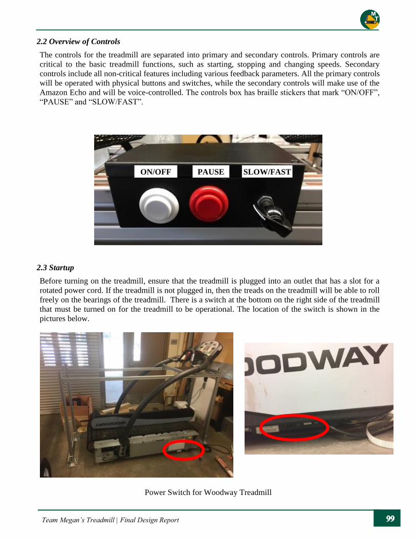
Team Megan’s Treadmill | Final Design Report
2.2 Overview of Controls
The controls for the treadmill are separated into primary and secondary controls. Primary controls are
critical to the basic treadmill functions, such as starting, stopping and changing speeds. Secondary
controls include all non-critical features including various feedback parameters. All the primary controls
will be operated with physical buttons and switches, while the secondary controls will make use of the
Amazon Echo and will be voice-controlled. The controls box has braille stickers that mark “ON/OFF”,
“PAUSE” and “SLOW/FAST”.
2.3 Startup
Before turning on the treadmill, ensure that the treadmill is plugged into an outlet that has a slot for a
rotated power cord. If the treadmill is not plugged in, then the treads on the treadmill will be able to roll
freely on the bearings of the treadmill. There is a switch at the bottom on the right side of the treadmill
that must be turned on for the treadmill to be operational. The location of the switch is shown in the
pictures below.
Power Switch for Woodway Treadmill
ON/OFF PAUSE SLOW/FAST
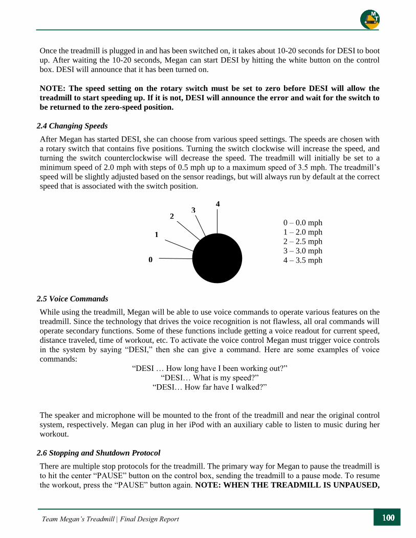
Team Megan’s Treadmill | Final Design Report
Once the treadmill is plugged in and has been switched on, it takes about 10-20 seconds for DESI to boot
up. After waiting the 10-20 seconds, Megan can start DESI by hitting the white button on the control
box. DESI will announce that it has been turned on.
NOTE: The speed setting on the rotary switch must be set to zero before DESI will allow the
treadmill to start speeding up. If it is not, DESI will announce the error and wait for the switch to
be returned to the zero-speed position.
2.4 Changing Speeds
After Megan has started DESI, she can choose from various speed settings. The speeds are chosen with
a rotary switch that contains five positions. Turning the switch clockwise will increase the speed, and
turning the switch counterclockwise will decrease the speed. The treadmill will initially be set to a
minimum speed of 2.0 mph with steps of 0.5 mph up to a maximum speed of 3.5 mph. The treadmill’s
speed will be slightly adjusted based on the sensor readings, but will always run by default at the correct
speed that is associated with the switch position.
2.5 Voice Commands
While using the treadmill, Megan will be able to use voice commands to operate various features on the
treadmill. Since the technology that drives the voice recognition is not flawless, all oral commands will
operate secondary functions. Some of these functions include getting a voice readout for current speed,
distance traveled, time of workout, etc. To activate the voice control Megan must trigger voice controls
in the system by saying “DESI,” then she can give a command. Here are some examples of voice
commands:
“DESI … How long have I been working out?”
“DESI… What is my speed?”
“DESI… How far have I walked?”
The speaker and microphone will be mounted to the front of the treadmill and near the original control
system, respectively. Megan can plug in her iPod with an auxiliary cable to listen to music during her
workout.
2.6 Stopping and Shutdown Protocol
There are multiple stop protocols for the treadmill. The primary way for Megan to pause the treadmill is
to hit the center “PAUSE” button on the control box, sending the treadmill to a pause mode. To resume
the workout, press the “PAUSE” button again. NOTE: WHEN THE TREADMILL IS UNPAUSED,
0
1
2 3
4
0 – 0.0 mph
1 – 2.0 mph
2 – 2.5 mph
3 – 3.0 mph
4 – 3.5 mph

Team Megan’s Treadmill | Final Design Report
IT WILL RETURN TO THE SPEED SETTING IT WAS ON BEFORE PAUSING! DESI will
announce the speed of the treadmill every time the user changes speeds.
When Megan is done with her workout, she must pause the treadmill and set rotary switch to the zero
position (the order is not important). Once DESI has completely stopped, Megan can turn off the system
by hitting the ON/OFF button once. DESI will announce that the system is turning off.
There are also multiple emergency stop protocols built into DESI. The dynamic sensor grid has inputs
from ultrasonic proximity sensors and capacitive sensors placed around the rail system seen below.
The proximity sensors are fixed to a stationary cross bar, located in front of the sliding rail, and are set to
detect the sliding rail’s location along its constrained path. If the sensors detect that Megan has been in
the fully extended position for more than a few seconds, the treadmill will slow down in small increments,
until Megan is able to keep pace closer to the front. If Megan remains at the back of her range of motion
for a certain period of time, the treadmill will pause to allow her to reset the speed setting.
The other key sensor on the treadmill is the capacitive sensor. A conductive copper tape has been attached
at all the gripping surfaces to ensure that there is always a point of contact for Megan while using the
treadmill. If the sensors detect that Megan is not in contact with any of these surfaces, an emergency stop
protocol will go into effect. Depending on the speed of the treadmill, DESI will end all the operations on
the treadmill within seconds and notify an emergency contact to assist Megan. This will activate a camera
feed of the treadmill to be sent to a desired phone for viewing.
3. Maintenance
The Woodway treadmill has a 100,000-mile warranty. The treadmill still has a significant lifetime left,
and has been recently inspected and cleared by a certified Woodway from Cal Poly. There is some simple
maintenance for the Desmo model treadmill that is specified by Woodway. See Attachment 1 for
Woodway’s User Manual to get the full details on maintenance of the treadmill. All of the 5/16” screws
that are put on the T-Slot are rated to 10 ft-lb of torque; however, if you are not in possession of a torque
wrench, hand tighten the fasteners all the way down to ensure none of the joints are loose. It is
recommended that the rails are inspected every 2-3 months to check for any loose joints. The fasteners
on the T-Slot require a 3/16” Hex Key for adjustments.

Team Megan’s Treadmill | Final Design Report
3.1 Railing System
The rails are made entirely from aluminum T-Slot. Most of the components have been anodized, which
means that they are resistant to rust and minor surface damages. Over time, it is likely that the parts will
endure cosmetic scratches; however, that will not affect the performance or quality of the overall system.
The rails are set on base feet that are fastened down to a ¾” plywood base with 5/16” lag screws with
hex-heads.
One of the main reasons the T-Slot was chosen for the rail system was for adjustability. The rails can be
moved up and down for various heights. If Megan ever feels uncomfortable with the current position, the
horizontal rails can be lowered along the vertical posts by loosening the fasteners, moving the rails to the
desired height, and tightening the fasteners back down. The fasteners for all of the rails are 5/16” screws,
which are tightened into nuts placed inside the T-Slot. There are two cross bars along the rails for added
stabilization. Since there is a grip inserted in the back half of the side rails, if the sliding linear bearings
need to be removed, it is necessary to remove the cross bars at the front of the treadmill. All the T-Slot
pieces have plastic caps on the end, which are held in place with push-in fasteners.
The sliding arm is placed on two linear bearings that sit on each horizontal rail. The control box and
handlebar sit on top of the sliding arm to provide an extended zone of operation for Megan on the
treadmill. The sliding rail can be taken off the linear bearings by removing the fasteners on the bottom of
the bearings. Note that these fasteners are not tightened down all the way to allow for easier movement
along the rails.
The sliding arm is limited by two stoppers that are fastened onto the horizontal rails. If Megan wants to
adjust the range of the sliding arm, the stoppers can be moved by loosening the fasteners and sliding them
along the horizontal rail. There is a handlebar that is set on the front of the sliding arm. This handlebar is
set in line with the linear bearings to help for a smooth sliding motion as Megan moves along the
treadmill. If Megan wants to work out without the sliding arm, it is possible to lock the arm by completely
restricting the motion with the stoppers.
END CAP WITH
PUSH IN FASTENER
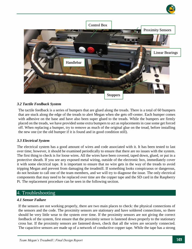
Team Megan’s Treadmill | Final Design Report
3.2 Tactile Feedback System
The tactile feedback is a series of bumpers that are glued along the treads. There is a total of 60 bumpers
that are stuck along the edge of the treads to alert Megan when she gets off-center. Each bumper comes
with adhesive on the base and have also been super glued to the treads. While the bumpers are firmly
placed on the treads, we have provided some extra bumpers to act as replacements in case some get forced
off. When replacing a bumper, try to remove as much of the original glue on the tread, before installing
the new one (or the old bumper if it is found and in good condition still).
3.3 Electrical System
The electrical system has a good amount of wires and code associated with it. It has been tested to last
over time; however, it should be examined periodically to ensure that there are no issues with the system.
The first thing to check is for loose wires. All the wires have been covered, taped down, glued, or put in a
protective sheath. If you see any exposed metal wiring, outside of the electronic box, immediately cover
it with some electrical tape. It is important to ensure that no wire gets in the way of the treads to avoid
tripping Megan and prevent from damaging the treadmill. If something looks conspicuous or dangerous,
do not hesitate to call one of the team members, and we will try to diagnose the issue. The only electrical
components that may need to be replaced over time are the copper tape and the SD card in the Raspberry
Pi. The replacement procedure can be seen in the following section.
4. Troubleshooting
4.1 Sensor Failure
If the sensors are not working properly, there are two main places to check: the physical connections of
the sensors and the code. The proximity sensors are stationary and have soldered connections, so there
should be very little wear to the system over time. If the proximity sensors are not giving the correct
feedback of the system, first ensure that the proximity sensor is fastened down properly to the stationary
cross bar. If the proximity sensors are fastened down, check that all the wires are securely connected.
The capacitive sensors are made up of a network of conductive copper tape. While the tape has a strong
Proximity Sensors
Control Box
Linear Bearings
Stoppers
Handlebar

Team Megan’s Treadmill | Final Design Report
adhesive, it is possible that over time the tape may peel. With a multimeter, it is possible to check if the
connection is maintained by checking the resistance from one end of the tape to another. If you do not
have a multimeter, a visual inspection should be sufficient in finding a break in the line. If there is a gap
between the copper tape, all you need to do is patch over the missing area to reconnect the circuit.
If there are no obvious signs of damaged wire or tape, it is possible that there is a problem with the
Raspberry Pi. We have attached a spare copy of DESI on an SD card that is located inside the electronics
box. All you need to do is turn off the system, switch out the SD cards, and let the system boot up. The
extra SD is just a backup, so please notify one of the members on the team if you end up switching it out.
4.2 Sliding Rail
If the sliding bar begins to catch along the rails there are a few possible ways to change the system. If the
bar is rotating too much, the fasteners on the bottom of the linear bearings may be too loose. The fasteners
use a 1/4” Hex-Key. Lightly tighten all the fasteners on each linear bearing to help keep the track in-line.
SD CARD
SLOT

Team Megan’s Treadmill | Final Design Report
If the side rails do not look parallel, then it may be necessary to adjust the end of the rails. To adjust the
side rail, loosen the fasteners that connect the side rail to the bracket on the vertical rail and realign the
horizontal rail.
Linear Bearing
Fasteners

Team Megan’s Treadmill | Final Design Report
Appendix T: Bill of Materials for Mechanical Systems

Team Megan’s Treadmill | Final Design Report
Appendix U: Bill of Material for Electrical Systems
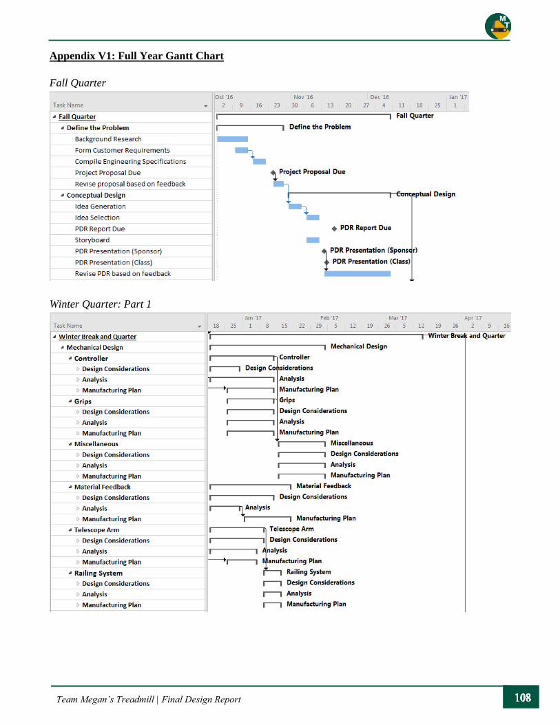
Team Megan’s Treadmill | Final Design Report
Appendix V1: Full Year Gantt Chart
Fall Quarter
Winter Quarter: Part 1
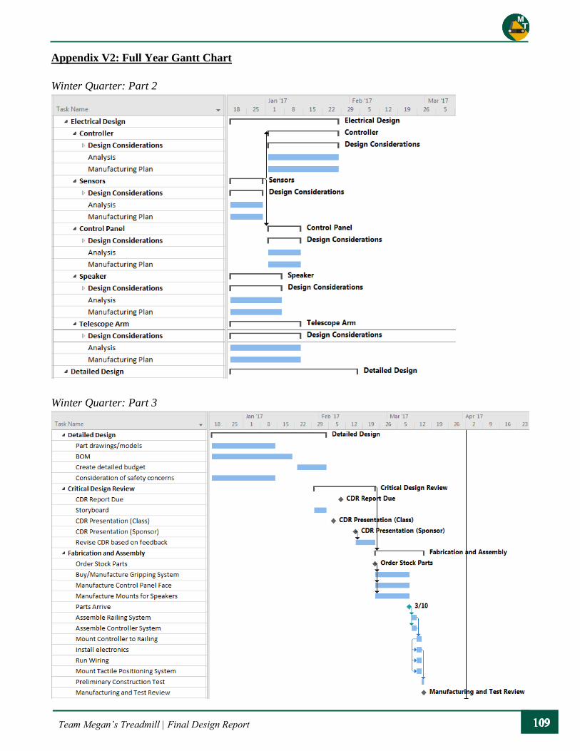
Team Megan’s Treadmill | Final Design Report
Appendix V2: Full Year Gantt Chart
Winter Quarter: Part 2
Winter Quarter: Part 3
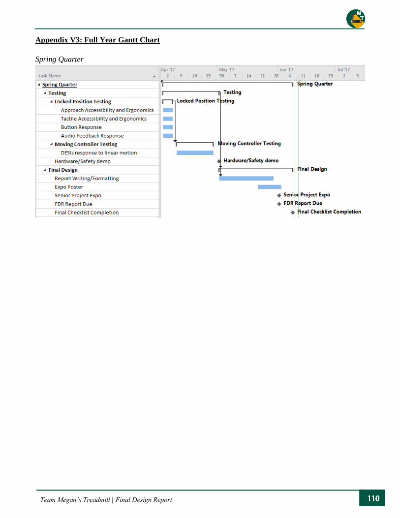
Team Megan’s Treadmill | Final Design Report
Appendix V3: Full Year Gantt Chart
Spring Quarter