MEET THE JOB SPECIFICATION FROM THE CUSTOMER the ...
16
MEET THE JOB SPECIFICATION FROM THE CUSTOMER the evaluation of a high wear resisting tool steel for a progressive die for the production of components of safety belts A. Wong Ngai Cheong Metal Industries Sdn Bhd Lot 41730 Bt 14, Jalan Puchong, 47100 Puchong, Selangor, Malaysia P.K.Thay Bohlasia Steels Sdn Bhd No. 9 Jalan SU 25, Taman Industri Selayang Utama, 68100, Selayang, Selangor, Malaysia W. Furtner B¨ ohler International GmbH Nordwestbahnstraße 12-14, A-1201 Wien, Austria H. Makovec, H. Eder, F. Russ B¨ ohler Edelstahl GmbH Mariazeller Straße 25, P.O. Box 96, A-8605 Kapfenberg, Austria 1285
Transcript of MEET THE JOB SPECIFICATION FROM THE CUSTOMER the ...

MEET THE JOB SPECIFICATION FROM THECUSTOMER
the evaluation of a high wear resisting tool steel fora progressive die for the production of components ofsafety belts
A. WongNgai Cheong Metal Industries Sdn Bhd
Lot 41730 Bt 14, Jalan Puchong,
47100 Puchong, Selangor, Malaysia
P.K.ThayBohlasia Steels Sdn Bhd
No. 9 Jalan SU 25, Taman Industri Selayang Utama,
68100, Selayang, Selangor, Malaysia
W. FurtnerBohler International GmbH
Nordwestbahnstraße 12-14,
A-1201 Wien, Austria
H. Makovec, H. Eder, F. RussBohler Edelstahl GmbH
Mariazeller Straße 25, P.O. Box 96,
A-8605 Kapfenberg, Austria
1285

1286 6TH INTERNATIONAL TOOLING CONFERENCE
Abstract For the production of components for safety belts in compliance with QS 9000and SPC control up to CPK >1.33, proper tool design and materials are de-manded. To fulfil the stamping requirement like no burr, no tear, 100% sharpedge on the locking tooth the progressive die construction (length 1500 mm)especially the position of the main and sub guides is important.
The output of 45 pieces per minute (two components will be produced atthe same time by using waste area of the strip) needs high performance pressesand tools. The monitoring of the process FMEA, the evaluation of cuttingedge geometric condition including frequency of grinding and service leadsto a tabulation of production records, SPC control data and CPK value. Thepaper discusses tool design, influence of processes, tool material selection,especially the results with BOHLER K190 MICROCLEAN and introducesthe next generation of frame die.
Keywords: Progressive die, tooling, die design, wear resistance, toughness, compressivestrength, stamping, press machines, knuckle link motion, crank link motiongeometric
INTRODUCTION
Increasing demand on quality and consistency placed on the productionof frame components for automotive safety belts (Fig. 1, R27frame) has ledto special focus on compliance with QS9000 and SPC control upto CPK >1.33.
This translates, in production terms, into extremely stringent stampingoperation that produces frame products with no burrs, no tear, and 100%sharp edge finish on the locking teeth at the gear area of the frame.
The progressive tooling for the production of this frame component hasto achieve an output of 45 pieces of frames per minute with twoparts beingproduced at the same time, one using the waste area of the metal strip.
Furthermore, the following criteria have also be taken intoconsiderationduring die design and construction:
1 high production quantity on HARD raw material, QSTE 550;
2 fine cut edge finish on the stamped components;
3 to achieve good consistency on the significant characteristic (SC) andcritical characteristic (CC) as specified by the customer;
4 to maintain a competitive price on the components producedto supportthe customer on their global purchasing program

Meet the Job Specification from the Customer 1287
Figure 1. Safety belt frames and strip (a), and after assembly (b).
The construction of the progressive tooling with a length ofover 1.500 mmwhich has to ensure the above targets are achieved would require carefulselection of tool materials, tool accessories, and the choice of an appropriatepress machine for the stamping and forming operations.
DIE DESIGN AND CONSTRUCTION
In order to ensure high and consistent quality on the frame componentsproduced on a mass production basis, the design of the tooling is based onthe major criteria described in the following paragraphs.
DIE CONSTRUCTION
The type of die construction for the components of this seat belt productis basically "progressive" in nature, Fig. 2, except for thelast process ofassembling the tie bars to the frame which requires a single process crimpingtool. Due to the frame and reinforce plate, the progressive tool has a dielength of 1.6 m and 0.8 m. Modular systems were used to ease thehandlingof process control and for easy model change and maintenance.
SPRING FORCE
The frame design demands fine cut finish on the edges, high clampingforce has thus become a major consideration to bring about high enoughforce to prevent the movement of the sheet metal during cutting.

1288 6TH INTERNATIONAL TOOLING CONFERENCE
Figure 2. Schematics of die construction, die clearance, and safety belt frame.
Low clamping force will result in the movement of the sheet metal duringcutting operation, and this would lead to:
1 tearing of sheet metal on the cutting edges instead of a control shearfinish;
2 shorter tool life caused by higher friction of sheet metal on the cuttingedges;
The bending of the frame into U-shape was done with a roller bending-upfriction-free process, which requires a high clamping force, otherwise, agood flatness and perpendicularity on the base of the bendingarea, and thusthe concentricity of the holes between the two sides would not be achieved.
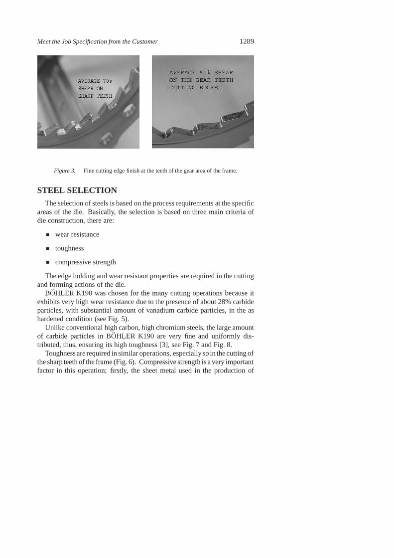
The stamping operation needs to perform a fine cutting edge finish onthe entire gear area frame (Fig. 3). However, the type of press use in thiscase is not a fine blanking press (long bolster area need to be used on theprogressive die). The fine cutting edge finish was achieved via a multipleshaving process with 2% shear clearance, with guiding elements of 14 µmpairing classification. The clamping force used in this operation was 40%(with N2 gas spring force of about 100 tonnes) that of the cutting force.
Meet the Job Specification from the Customer 1289
Figure 3. Fine cutting edge finish at the teeth of the gear area of the frame.
STEEL SELECTION
The selection of steels is based on the process requirementsat the specificareas of the die. Basically, the selection is based on three main criteria ofdie construction, there are:
wear resistance
toughness
compressive strength
The edge holding and wear resistant properties are requiredin the cuttingand forming actions of the die.
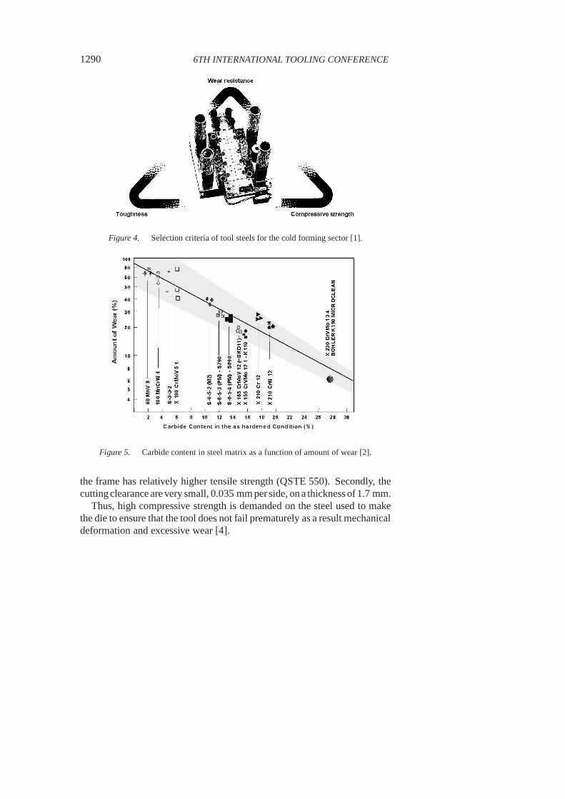
BOHLER K190 was chosen for the many cutting operations because itexhibits very high wear resistance due to the presence of about 28% carbideparticles, with substantial amount of vanadium carbide particles, in the ashardened condition (see Fig. 5).
Unlike conventional high carbon, high chromium steels, thelarge amountof carbide particles in BOHLER K190 are very fine and uniformly dis-tributed, thus, ensuring its high toughness [3], see Fig. 7 and Fig. 8.
Toughness are required in similar operations, especially so in the cutting ofthe sharp teeth of the frame (Fig. 6). Compressive strength is a very importantfactor in this operation; firstly, the sheet metal used in theproduction of
1290 6TH INTERNATIONAL TOOLING CONFERENCE
Figure 4. Selection criteria of tool steels for the cold forming sector [1].
Figure 5. Carbide content in steel matrix as a function of amount of wear [2].
the frame has relatively higher tensile strength (QSTE 550). Secondly, thecuttingclearance are very small, 0.035 mm per side, ona thickness of 1.7 mm.
Thus, high compressive strength is demanded on the steel used to makethe die to ensure that the tool does not fail prematurely as a result mechanicaldeformation and excessive wear [4].

Meet the Job Specification from the Customer 1291
Figure 6. Punch and die for cutting the sharp teeth of the frame.
BOHLER K340 was chosen for its high adhesive wear resistance and itsexcellent suitability to PVD coating.
Figure 7. BOHLER K190 exhibits high level of toughness [1].
BOHLER K340 was used mainly in the forming and bending operationswhere the area of contact between the tool and the sheet metalwas large. This

1292 6TH INTERNATIONAL TOOLING CONFERENCE
Figure 8. The compressive strength of BOHLER K190 is comparable to that of high speedsteels [4].
contact tends to give rise to adhesive wear. The adhesive wear resistance ofBOHLER K340 is relatively higher than conventional 12% chromium steel[5] as shown in Fig. 9. The high adhesive wear resistance of BOHLER K340is achieved by the special alloying of aluminium and niobium.
The adhesive wear resistance of K340 in this particular operation is fur-ther enhanced by PVD coating. K340 responds exceptionally well to PVDcoating; this may be attributed to the presence of aluminiumin its matrixand also its hardness retention property at high temperatures.
Table 1. Summary of tool steels used in the construction of the progressive die
Steel C Si Mn Cr Mo V Others
BOHLER K190 MICROCLEAN 2.30 0.40 0.40 12.50 1.10 4.00 —BOHLER K340 ISODUR 1.10 0.90 0.40 8.30 2.10 0.50 +Al, +NbBOHLER K110 1.55 0.25 0.35 11.80 0.80 0.95 —

Meet the Job Specification from the Customer 1293
Figure 9. Adhesive wear resistance of BOHLER K340 [4].
PROGRESSIVE DIE SAFETY FEATURE
The demand on the production of a large quantity of products on a singletool, and the need to share special and expensive press machine with otherproducts, scheduling of production becomes very importantto avoid unnec-essary downtime. Also, tool and press machine failure due toaccident mustbe avoided. Thus, safety features in the progressive die assembly has animportant roll in minimising the down time caused by mishandling duringbusy production schedules.
1 A misfeed pilot with a photo sensor is used to monitor the feedingduring the progressive run.
2 At the end of the progressive die where the finished parts areejected,a mis-eject sensor is installed.
3 At certain critical areas along the progressive die, stroke-end limitsensors with sensitivity between 2 and 50 µm are installed tomonitorthe average gap of the die close position. Any deviation fromthesetting caused by the presence of shearing chips or scraps, or otherforeign objects will trigger the sensors and stop the press.
4 A load cell is also installed in the press to monitor all the forces used atthe various stages of the operation. This not only allows force analysis

1294 6TH INTERNATIONAL TOOLING CONFERENCE
to be done on every stage during the try out adjustment and calibration,but also safeguard the tooling from unexpected and excessive loadduring the progressive operation.
SELECTION OF PRESS MACHINE
In the selection of the right press machine for the stamping of the seat-beltframe, the criteria as summarised in Table 2 were considered.
Table 2. Summary of features of the press machine
Press Characteristics Requirements
Press Force The frame product requires a 300-tonne pressPress Bolster Minimum 2-meter bolster in this caseSlide Stroke Slide stroke is related to the finish product height after drawing,
forming or bending. A simple rule of thump is the minimum slideopening height has to be at least 2 X’s product height.(A slide opening height of 100 mm was used in this case.)
Stroke per minute The rate of the frame production is 45 strokes per minutePress Frame H-Frame press was used
OPERATIONS AND RESULTS
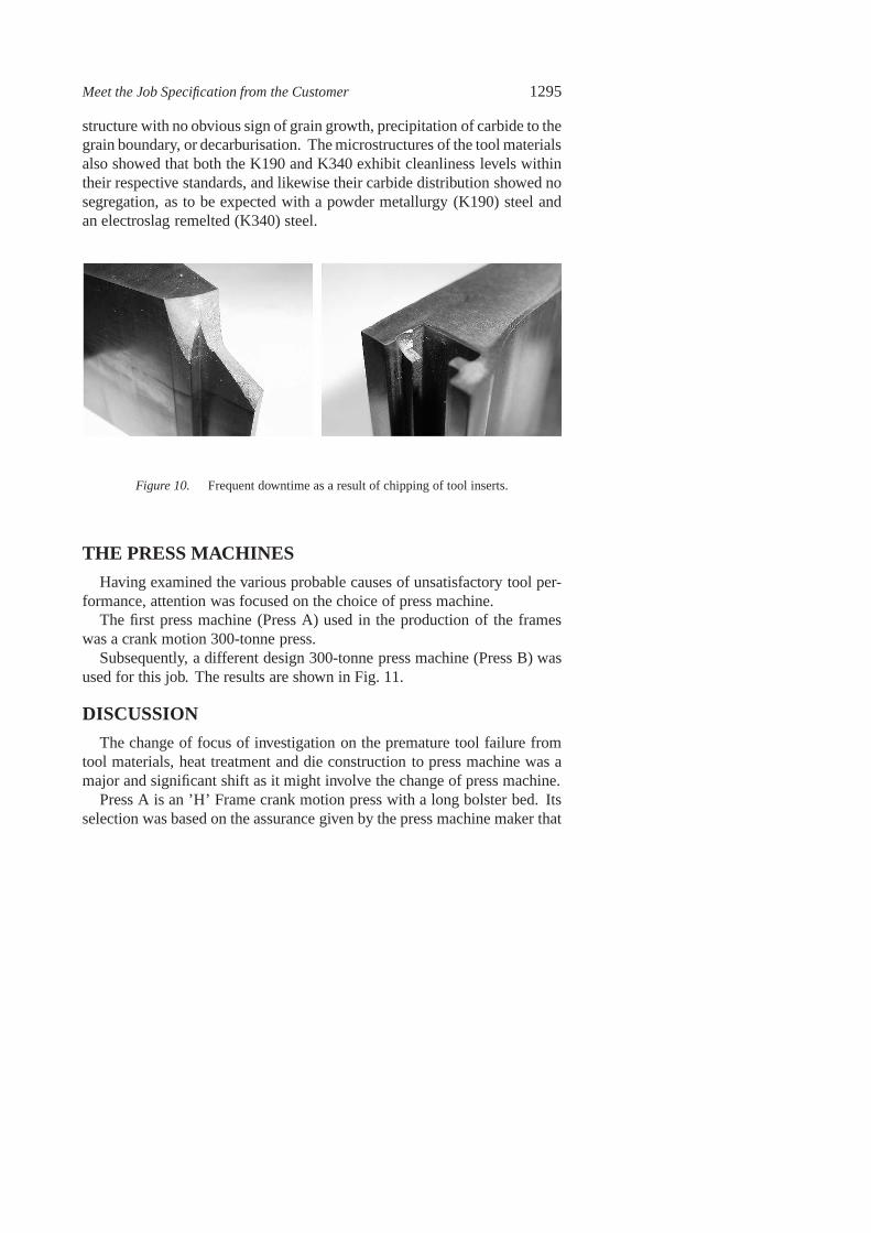
The try-outs and sampling of the R27 frame production went smoothly;however, during the production run, unexpected and frequent tool breakageand excessive tool wear were encountered, Fig. 10.
QUALITY OF HEAT TREATMENT AND STEELS
An investigation was launched to look into this problem starting with thefeeding of the coil, tool setup and operation, the quality ofheat treatmentand tool materials, and also the press machine.
The feeding of the coil into the progressive tool was due to the initialinexperience in the handling of high tensile coil and it was overcome withpractice.
Metallurgical investigation was carried out to determine if heat treatmentand/or tool material might have been the problem. Observation of the mi-crostructures revealed that the structures were that of a proper heat treated
Meet the Job Specification from the Customer 1295
structure with no obvious sign of grain growth, precipitation of carbide to thegrain boundary, or decarburisation. The microstructures of the tool materialsalso showed that both the K190 and K340 exhibit cleanliness levels withintheir respective standards, and likewise their carbide distribution showed nosegregation, as to be expected with a powder metallurgy (K190) steel andan electroslag remelted (K340) steel.
Figure 10. Frequent downtime as a result of chipping of tool inserts.
THE PRESS MACHINES
Having examined the various probable causes of unsatisfactory tool per-formance, attention was focused on the choice of press machine.
The first press machine (Press A) used in the production of theframeswas a crank motion 300-tonne press.
Subsequently, a different design 300-tonne press machine (Press B) wasused for this job. The results are shown in Fig. 11.
DISCUSSION
The change of focus of investigation on the premature tool failure fromtool materials, heat treatment and die construction to press machine was amajor and significant shift as it might involve the change of press machine.
Press A is an ’H’ Frame crank motion press with a long bolster bed. Itsselection was based on the assurance given by the press machine maker that
1296 6TH INTERNATIONAL TOOLING CONFERENCE
it was capable of carrying out the specified job. The shorter delivery time ofthe machine also played a very crucial role in choosing this machine.
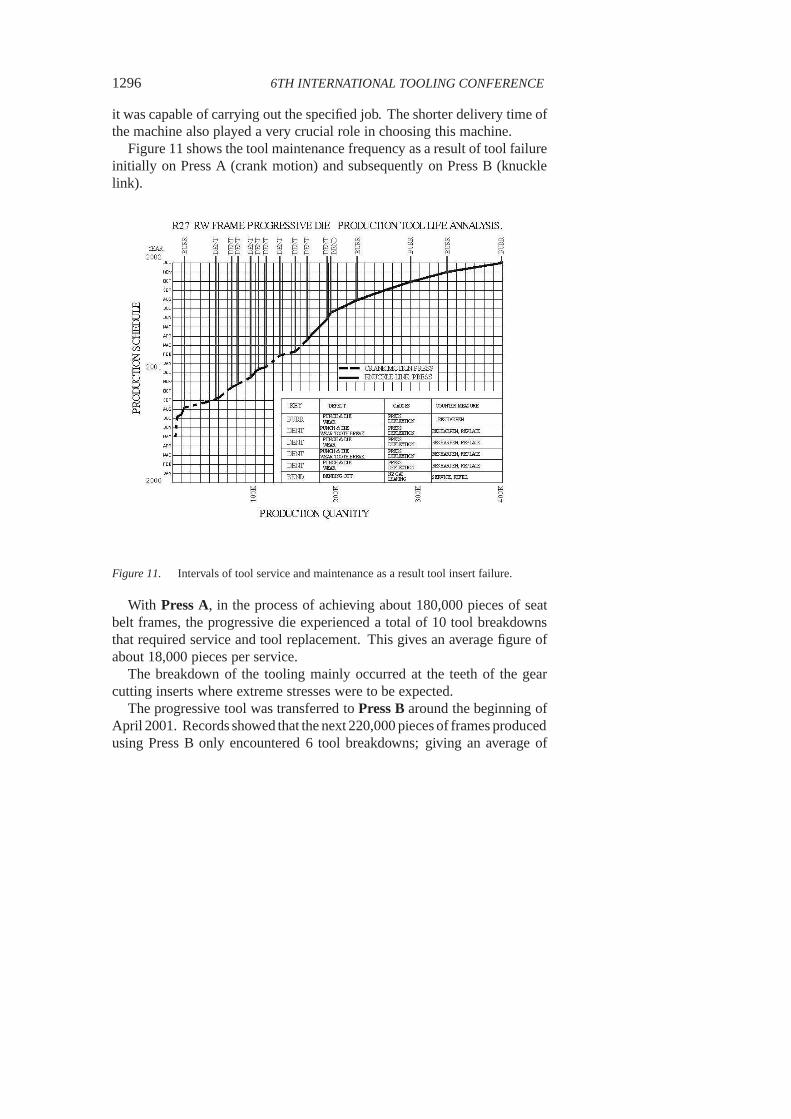
Figure 11 shows the tool maintenance frequency as a result oftool failureinitially on Press A (crank motion) and subsequently on Press B (knucklelink).
Figure 11. Intervals of tool service and maintenance as a result tool insert failure.
With Press A, in the process of achieving about 180,000 pieces of seatbelt frames, the progressive die experienced a total of 10 tool breakdownsthat required service and tool replacement. This gives an average figure ofabout 18,000 pieces per service.
The breakdown of the tooling mainly occurred at the teeth of the gearcutting inserts where extreme stresses were to be expected.
The progressive tool was transferred toPress B around the beginning ofApril 2001. Records showed that the next 220,000 pieces of frames producedusing Press B only encountered 6 tool breakdowns; giving an average of

Meet the Job Specification from the Customer 1297
about 36,000 pieces per service. The progressive die is currently running at45 strokes per minute. This change is very significant as the frequency ofservice was halved as a result of changing the press, not the tooling.
Press A has a long bolster bed, and it was suspected that the deflectionof the bolster bed during close die position might have been an importantfactor in influencing the performance of the tool.
A measurement was taken and it was found that the deflection atthe centrewas 0.900 mm (Fig. 12). This deflection obviously would be transferred tothe die that the bolster bed supposed to support.
Figure 12. Schematics of bolster deflection of crank and knuckle link motion presses.
Press B is specifically designed and developed for parts thatrequire finecutting edge finish and cold forging process. It incorporates a knuckle andlink motion that allows it a 30s holding time (Fig. 13) beforeand after thebottom dead centre (BDC). Figure 14 shows a knuckle link motion press inoperation.
The bolster design of Press B was much stronger. It was a single-piececasting, and the deflection of the bolster bed under a maximumload of 300tonnes in a close die position was only 0.030 mm (Fig. 12) at the centre.

1298 6TH INTERNATIONAL TOOLING CONFERENCE
Figure 13. Motion curves of crank and knuckle link presses [6].
Figure 14. Press B – Knuckle link motion press in operation.
CONCLUSION
The case study above points to the fact that despite the use ofbest possibletool materials with special attention on tool design, the tooling may still

Meet the Job Specification from the Customer 1299
Figure 15. The three basic elements of influence in press work.
perform well below expectation if the quality of the press machine is notsatisfactory.
In the construction of the progressive die, both electroslag remelted (ESR)and powder metallurgical quality steel grades were used at the most criticaland severely stressed areas to ensure minimum unscheduled downtime dueto tool material failure.
To achieve greater production efficiency, it can be concluded that threebasic elements: die design, material selection, and press machines mustwork harmoniously and compliment each other (Fig. 15).
ACKNOWLEDGMENTS
The authors wish to thank Autoliv Asia Pacific and Ngai CheongMetalIndustries Sdn Bhd for their permission in allowing the publication of thiscase study.
REFERENCES
[1] E. PUTZGRUBER and H. MAKOVEC, Bohler Edelstahl Internal Circular, 1993.
[2] B. HRIBERNIK, G. HACKL, H. LENGER, Anwendungsmoglichkeiten von pulver-metallurgisch hergestellten Werkzeugstahlen, BHM 134 (1989), p.338-341.
[3] C. TORNBERG and P. BILLGREN, Proceedings of the 1st International High SpeedSteel Conference, Leoben, 26 - 28 Mar, 1990, edited by G. Hackl and B. Hribernik(Klampfer, Weiz, 1990), p. 108.

1300 6TH INTERNATIONAL TOOLING CONFERENCE
[4] Bohler Edelstahl Technical Data (2001), p. 15.
[5] H. SCHWEIGER, H. LENGER, A. STIX, Proceedings of the 4th International Con-ference on Tooling, Bochum, 11 - 13 Sep, 1996, edited by H. Berns, H. Hinz, M.Hucklenbroich, (Verlag Schurmann + Klagges, Bochum, 1996), p. 109.
[6] Patec Technical Data, p. 3.