MEDO LA BLOWER - CWWScwws.com.au/nitto la80 manual.pdf · 1 MEDO blowers are OILLESS. Never...
12
This instruction manual should be read and understood thoroughly before any installation and maintenance work is executed. After reading this instruction manual, please keep it handy for reference. MEDO LA BLOWER INSTRUCTION MANUAL INSTALLATION & MAINTENANCE LA-28B/ LA-45B LA-60B/ LA-80B LA-100/ LA-120
-
Upload
truongduong -
Category
Documents
-
view
217 -
download
0
Transcript of MEDO LA BLOWER - CWWScwws.com.au/nitto la80 manual.pdf · 1 MEDO blowers are OILLESS. Never...

This instruction manual should be read and understood thoroughlybefore any installation and maintenance work is executed.
After reading this instruction manual, please keep it handy for reference.
MEDO LA BLOWERINSTRUCTION MANUAL
INSTALLATION & MAINTENANCE
LA-28B/ LA-45B
LA-60B/ LA-80B
LA-100/ LA-120
1. Model and Specifications
2. Dimensions
3. Safety Instruction
4. Installation (Septic tank application)
5. Maintenance
Parts List
Parts List
Parts List
(LA-28B LA 45B/ - )
(LA-60B LA 80B/ - )
(LA-100 LA 120/ - )
CONTENTS
2
2
3
4
5
8
9
10
1

L=207mmW=182mmH=205mmD=18mmOD
L=307mmW=190mmH=208mmD=18mmOD
L=408mmW=210mmH=232mmD=26mmAD
Model LA 28B- -LA 45B -LA 60B -LA 80B -LA 100 -LA 120
Standard Voltage * 230V AC
Rated Frequency 50Hz
Rated Pressure 110mbar 150mbar 180mbar
Operating Pressure50 - 180mbar 100 - 200mbar 100 - 250mbar
0,05 - 0,18 bar 0,1 - 0,2 bar 0,1 - 0,25 bar
Rated Airflow 28l/min. 45l/min. 60l/min. 80l/min. 100l/min. 120l/min.
Power Consumption 29 W 47 W 64 W 86 W 100 W 130 W
Weight 2.9kg 3.0kg 5.0kg 5.3kg 9.4kg 9.4kg
* The unit must only be operated at the voltage as indicated on the outer casing of the blower.
2. Dimensions
Label
Label
LA-28B/LA-45B
LA-60B/LA-80B
Label
LA-100/LA-120
D
D
HH
H
L
L
L W
W
W
D
2
1. Model and Specifications
AD
L=305mmW=214mmH=188mmD=18mmAD
IP Class 55 55 55 55 55 55
3
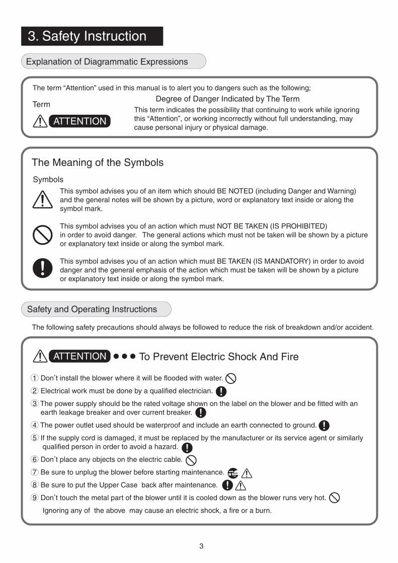
The term “Attention” used in this manual is to alert you to dangers such as the following;
Degree of Danger Indicated by The TermThis term indicates the possibility that continuing to work while ignoringthis “Attention”, or working incorrectly without full understanding, maycause personal injury or physical damage.
The Meaning of the Symbols
SymbolsThis symbol advises you of an item which should BE NOTED (including Danger and Warning)and the general notes will be shown by a picture, word or explanatory text inside or along thesymbol mark.
This symbol advises you of an action which must NOT BE TAKEN (IS PROHIBITED)in order to avoid danger. The general actions which must not be taken will be shown by a pictureor explanatory text inside or along the symbol mark.
This symbol advises you of an action which must BE TAKEN (IS MANDATORY) in order to avoiddanger and the general emphasis of the action which must be taken will be shown by a pictureor explanatory text inside or along the symbol mark.
The following safety precautions should always be followed to reduce the risk of breakdown and/or accident.
To Prevent Electric Shock And Fire
1 Don,t install the blower where it will be flooded with water.
2 Electrical work must be done by a qualified electrician.
3 The power supply should be the rated voltage shown on the label on the blower and be fitted with anearth leakage breaker and over current breaker.
4 The power outlet used should be waterproof and include an earth connected to ground.
5 If the supply cord is damaged, it must be replaced by the manufacturer or its service agent or similarlyqualified person in order to avoid a hazard.
6 Don,t place any objects on the electric cable.
7 Be sure to unplug the blower before starting maintenance.
8 Be sure to put the Upper Case back after maintenance.
9 Don,t touch the metal part of the blower until it is cooled down as the blower runs very hot.
Ignoring any of the above may cause an electric shock, a fire or a burn.
ATTENTION
3. Safety Instruction
Explanation of Diagrammatic Expressions
ATTENTION
Term
Safety and Operating Instructions

1. Installation site selection
Install our blower near the septic tank.If the pipeline is long, the sewage treatment may not perform well due to an insufficient airflow.Install in a place which is convenient for maintenance.Don
,t install over a manhole or on soft ground.
Avoid areas where wind-blown leaves and dust gathers.Install in a well ventilated place.Install at least 30cm away from the wall of a house.Installation in the shade is recommended to suppress heat generation of the blower.Doninstalled over the water level ot the sewage tank/aquarium to avoid any backflow of the water.If the blower is installed under the water level a backflow valve must be used.
,t install the blower where it will be flooded with water. Make sure that the blower is
Don,t install where there is excess moisture or humidity.
2. Method of Installation
The base should be made of concrete strong enough to bear the weight and block vibration fromthe blower.The base should be at least 10cm above the ground level and 5cm larger than the externaldimensions of the blower.Provide a separate power outlet to be only used for the blower.Electrical work must be done by a qualified electrician.The power supply should be the rated voltage shown on the label on the blower and be fitted withan earth leakage breaker and over-current breaker.The power outlet used should be waterproof and include an earth connected to ground.Place the blower horizontally on the base.A soft rubber hose must be used for connection between the air outlet of the blower and the pipe.The rubber hose must be fastened with hose clamps.When making the connection, level the air outlet and the pipe to ensure the hose is not kinked orblocked.Before starting the operation of the blower, ensure that the water level in the septic tank isappropriate and the valves on the pipeline are properly opened.
3. Start operation
Insert the power plug into the power outlet with full contact so that the plug itself does not wobble.Incomplete connection may cause an electric shock or a fire.After starting operation ensure that there is;
No air leakage from the hose and the pipe connection.No abnormal noise from the blower.No vibration transmitted to the ground due to strained piping.
4
Blower
Blower
Base
Base
Water tank or Pond
Hose
Hose
Water level
Air outlet of BlowerHose clamp
Hose clamp
Aerobic SewageTreatment Tank
Earth Leakage BreakerOver Current Breaker
Waterproof PowerOutlet with grounding
Power Distribution Line
4. Installation (Septic Tank Application)
1
1
2
345
678910
11
2345678
9

3. Safety Instruction
1. Cautions1 MEDO blowers are OILLESS. Never lubricate them.2 All blowers have already been precisely adjusted. Never disassemble them.
(Do not try to loosen the Hex. bolts on the Endcap)
2. Replacement of Filter Element1 Be sure to unplug the blower before starting the replacement work.2 Loosen the Bind Screw 1 and remove the Filter Cover 4 .3 Remove the Filter Element(s) 5 from the Upper Case 6 and replace with new
One(s). At the same time, clean the air inlet of the Filter Cover 4 and the UpperCase 6 .
4 Assemble the Filter Cover 4 with the Filter Cover Gasket 3 securely positioned.5 Mount the Filter Cover 4 to the Upper Case 6 , then tighten with the Bind Screw(s) 1 .6 Time to replace the Filter Element
It is recommended that the Filter Element(s) is cleaned or replaced with new one(s)depending on the extent of its deterioration as determined by the atomospheric conditionsaround the application. The filter element(s) should be checked every three monthsand should be replaced jearly.
3. Replacement of Piston Set Assy1 Be sure to unplug the blower before starting the maintenance work.2 Remove the Upper Case 6 , loosen all the Hex. Bolts 9 on the Headcover 10 and remove it. In
case it is hard to remove the Headcover 10 insert a flat head screwdriver to the slot(s) on theedge of the Headcover 10 and twist the screwdriver gently to open.
3 Take out the Piston Set Assy(s).4 Replace all Piston Set Assys, Gasket A 11 and Gasket B 12 with new ones.
Be sure to keep the Teflon Seal of the Piston 13 away from any dust, swarf,water, oil or grease. Try not to touch the Teflon Seal of the Piston 13 with your fingers.
5 Insert the Piston Set Assy(s) into the Pump Body. Install Gasket A 11 on theHeadcover 10 and Gasket B 12 on the Pump Body, then fasten the Headcover 10with the Hex. Bolts 9 .Tighten the Hex. Bolts 9 evenly and alternately then gradually fully tighten.
6 Before putting the Upper Case 6 back, start the blower and check if there is anyair along the Headcover 10 or the Nozzle Seal(s)leakage 33 by briefly blocking the air outlet.In case there is an air along the Headcover 10 , re-position Gasket A 11 andleakageGasket B 12 then re-fasten the Hex Bolts 9 . In case there is an air along the NozzleleakageSeal(s) 33 chec k if the nozzle seal is installed on the airtank properly and press the pump bodydown to allow the outlet port of the Headcover to catch the Nozzle Seal(s) correctly.
7 Put the Upper Case 6 back after installing GasketC 8 on the Bottom Caseproperly. Fasten the Bind Screws/Torx Screws 7 evenlyand alternately.
8
5
5. Maintenance (Refer the sketches on the next page)
Slot
Teflon Seal
Piston
Piston Set Assembly replacement periodIt is suggested that the Piston Set Assembly is replacedevery 24 months resp. after 20.000 h depending on theextent of the blower´s pressure and airflow deterioration.There is a groove on each Teflon Seal of the Pistonindicating the degree of wear. If one or both grooves areworn away, replacement of the Piston Set Assembly isrecommended.

6
Bind Screw
Torx Screw
Torx Screw
19 Spring
19 Spring
19 Spring
18 Spring Seat
18 Spring Seat
13 Piston
13 Piston
13 Piston
12 Gasket B
12 Gasket B
12 Gasket B
12 Gasket B
11 Gasket A
11 Gasket A
11 Gasket A
10 Headcover
10 Headcover
10 Headcover
9 Hex Bolt
9 Hex Bolt
8 Gasket C
8 Gasket C
8 Gasket C
7 Bind Screw
7Torx Screw
6 Upper Case
6 Upper Case
6 Upper Case
5 Filter Element
5 Filter Element
5 Filter Element
4 Filter Cover
4 Filter Cover
4 Filter Cover
3 Filter Cover Gasket
3 Filter Cover Gasket
3 Filter Cover Gasket
1 Bind Screw
1 Bind Screw
7 Bind Screw
1 Bind Screw
29 Hex Bolt
32 Nozzle Seal
32 Nozzle Seal
33 Nozzle Seal
Air Outlet
Blower Body
Blower Body
Bottom Case
Bottom Case
Bottom Case
Never loosen these four (4) Hex.Bolts on the Endcap.
Outlet Port
Outlet Port
Outlet Port
Slot for screwdriver
Slot for screwdriver
Slot forscrewdriver
Never loosen these eight (8) Hex.Bolts on the Endcap.
Blower Body
Air Outlet
Air Outlet
Piston Set A'ssy
Never loosen these twelve (12) Hex.Bolts on the Endcap.
Piston Set A'ssy
Piston Set A'ssy
LA 28B/ LA 45B- -
LA 60-A / LA 80A-
LA 100/ LA 120- -
LA-60B/LA-80B

4. Purchasing suggestion for the maintenance parts
1 Filter Element
Model Part No. Quantity
LA 28B/LA 45B/LA 100/LA 120- - - - LB02369 10pcs.set
LA 60B/LA 80B- - LB03937 10pcs.set
2 Repair Parts Kit
Model Part No. Quantity
LA 28B- LB01288 1 set
LA 45B- LB03514 1 set
LA 60B- LB03519 1 set
LA 80B- LB03517 1 set
LA 100/LA 120- - LB04151 1 set
3 Contents of Repair Parts Kit
Parts Included LA 28B/LA 45B- - LA 60B/LA 80B- - LA 100/LA 120- -
5 Filter Element 1 1 2
11 Gasket A 1 2 3
12 Gasket B 1 2 3
13 Piston 1 2 3
18 Spring Seat 1 2 3
19 Spring 1 2 3
7
Piston BossSpring Spring Seat
Grease
Teflon Seal
Piston sectional view
Cautions
Locat the spring into the piston by rotating it clockwise.Check that grease is present on the convex face of the spring seat.( If no grease is present, please contact your supplier)Never use standard grease as it may cause a malfunction.Keep the Teflon Seal away from any dust, swarf, water, oil or grease.

No. Part Name LA28B Q'ty LA45B Q'ty No. Part Name LA28B Q'ty LA45B Q'ty
1 Bind Screw LP30581 1 LP30581 1
2 Seal Washer LP30635 2 LP30635 2
3 Filter Cover Gasket LQ02607 2 LQ02607 2
4 Filter Cover LQ02575 1 LQ02575 1
5 Filter Element LQ02605 1 LQ02605 1
6 Upper Case LB02937 1 LB02937 1
7 Bind Screw UL LP30581 4 LP30581 4
Torx Screw CE LQ03082 4 LQ03082 4
8 Gasket C LQ02601 1 LQ02601 1
9 Hex Bolt LP31316 4 LP31316 4
10 Headcover LQ02567 1 LQ02063 1
11 Gasket A LQ01043 1 LQ01043 1
12 Gasket B LQ01042 1 LQ01042 1
13 Piston LA70625 1 LB03132 1
Piston Sub Assy LA70626 1 LB03133 1
Inlet Valve LP30916 1 LP30916 1
Valve Retainer A LP11548 1 LP11548 1
CS Ring LP12948 1 LP12948 1
18 Spring Seat LP12155 1 LP12155 1
19 Spring LP30620 1 LQ02743 1
20 Housing LB03184 1 LB03184 1
SE Ring LP12475 2 LP12475 2
Valve Retainer B LP13735 2 LP13735 2
23 Outlet Valve LP10359 2 LP10359 2
24 Screw 5 x 20 LP12599 2 LP12599 2
25 Insulation Bush LP10355 2 LP10355 2
26 Rear Cylinder LA71843 1 LA71843 1
27 Field Core Assy P LB01536 1 LB03466 1
Field Core Assy Q
Field Core Assy E LB04038 1 LB04028 1
28 Endcap LQ01052 1 LQ02892 1
29 Hex Bolt LP31316 4 LP31316 4
30 Rubber Feet LQ04256 4 LQ04256 4
31 Cable Assy UK LB05341 1 LB05341 1
Cable Assy D LB05307 1 LB05307 1
Cable Assy A
Cable Assy J LQ01037 1 LQ01037 1
Cable Assy UL LB04770 1 LB04770 1
32 Nozzle Seal LQ02598 1 LQ02598 1
33 Air Tank Assy LB02987 1 LB02987 1
34 Joint Hose LQ02602 1 LQ02602 1
35 Bottom Case LB02938 1 LB02938 1
36 Cushion
37 Rubber Plug
OPTION
38 Hose Assy
LA97475 LB03185
22
21
17
16
15
14
8
12345
678
1819
1314
1516
179
1211
10
30
31
32
33 34
30
3538
20
232221
2625
27
2829
24
Exploded View LA-28B LA 45B/ -
Parts List

LA97475 LB03185
9
Parts List
Exploded ViewLA-60B LA 80B/ -
No. Part Name LA-60B Q'ty LA-80B Q'ty No. Part Name Q'ty LA-80B Q'ty
1 Bind Screw LP30581 1 LP30581 1 22 Endcap 1 LQ03767 1
2 Seal Washer LP30635 2 LP30635 2 Endcap (Thermal) 1 LQ05321 1
3 Filter Cover Gasket LQ02607 2 LQ02607 2 23 Hex Bolt 8 LP31316 8
4 Filter Cover LB06202 1 LB06202 1 24 Rubber Feet 4 LQ05143 4
5 Filter Element LQ02730 1 LQ02730 1 25 Cable Assy UK 1 LB05341 1
6 Upper Case LB06203 1 LB06203 1 Cable Assy D 1 LB05307 1
7 Bind Screw UL LP30581 6 LP30581 6 Cable Assy A 1 LB06463 1
Torx Screw CE LQ03082 6 LQ03082 6 Cable Assy J 1 LB00914 1
8 Gasket C LQ05144 1 LQ05144 1 Cable Assy UL 1 LB04770 1
9 Hex Bolt LP31316 6 LP31316 6 26 Bottom Case 1 LB06205 1
10 Headcover Assy LB06207 1 LB06207 1 27 Joint Hose 1 LQ05142 1
11 Gasket A LQ01043 2 LQ01043 2 28 Clamp 2 LP13171 2
12 Gasket B LQ01042 2 LQ01042 2
13 Piston Assy LB03132 2 LB03132 2 29
14 Spring LP30585 2 LQ02743 2
15 Spring Seat LP12155 2 LP12155 2
16 Housing Assy LB03184 2 LB03184 2
17 Rubber Plug LQ03775 1 LQ03775 1
18 Rear Cylinder LB02443 2 LB02443 2
19 Insulation Bush LP10355 4 LP10355 4
20 Screw 5 x 20 LP12599 4 LP12599 4
21 Field Core Assy P LB04901 1 LB04905 1
Field Core Assy Q LB05126 1 LB05134 1
Field Core Assy E LB05099 1 LB05048 1
LA97475 LB03185
LP13171
OPTION
Hose Assy
LB00914
LB04770
LQ05142
LA-60B
LP31316
LQ05143
LQ03767
LQ05321
LB05341
LB05307
LB06463
LB06205

LA100 LA120 LA100 LA120
LP30581 2 LP30581 2
LP30635 4 LP30635 4
LQ03101 2 LQ03101 2
LB30769 1 LB30769 1
LQ02605 2 LQ02605 2
LB03763 1 LB03763 1
LP30581 8 LP30581 8
LQ03082 8 LQ03082 8
LQ03091 1 LQ03091 1
LP31316 12 LP31316 12
LB03834 1 LB03834 1
LQ01399 3 LQ01399 3
LQ01400 3 LQ01400 3
LB03779 3 LB03779 3
LB03780 3 LB03780 3
LQ03230 3 LQ03230 3
LP11548 3 LP11548 3
LP12948 3 LP12948 3
LP10357 3 LP10357 3
LQ03117 3 LQ03117 3
LB03778 3 LB03778 3
LP12475 6 LP12475 6
LP13735 6 LP13735 6
LP10359 6 LP10359 6
LP12599 6 LP12599 6
LP10355 6 LP10355 6
LB01415 3 LB01415 3
LB04855 1 LB04909 1
LB04280 1
LB04180 1 LB04171 1
LQ03108 1 LQ03108 1
LP31316 12 LP31316 12
LQ03089 6 LQ03089 6
LB05341 1 LB05341 1
LB05307 1 LB05307 1
LB05220 1
LQ01037 1 LQ01037 1
LB04770 1 LB04770 1
LQ02598 2 LQ02598 2
LB03771 1 LB03771 1
LQ03096 1 LQ03096 1
LB03762 1 LB03762 1
LQ03112 1 LQ03112 1
LB04119 LB03965 LB01070
No. Part Name Q'ty Q'ty No. Part Name Q'ty Q'ty
1 Bind Screw
2 Seal Washer
3 Filter Cover Gasket
4 Filter Cover
5 Filter Element
6 Upper Case
7 Bind Screw UL
Torx Screw CE
8 Gasket C
9 Hex Bolt
10 Headcover
11 Gasket A
12 Gasket B
13 Piston
Piston Sub Assy
Inlet Valve
Valve Retainer A
CS Ring
18 Spring Seat
19 Spring
20 Housing
SE Ring
Valve Retainer B
23 Outlet Valve
24 Screw 5 x 20
25 Insulation Bush
26 Rear Cylinder
27 Field Core Assy P
Field Core Assy Q
Field Core Assy E
28 Endcap
29 Hex Bolt
30 Rubber Feet
31 Cable Assy UK
Cable Assy D
Cable Assy A
Cable Assy J
Cable Assy UL
32 Nozzle Seal
33 Air Tank Assy
34 Joint Hose
35 Bottom Case
36 Cushion
37 Rubber Plug
Hose Assy
OPTION
38
22
21
17
16
15
14
10
LA-100 LA 120/ -
1415
1918
23
2625
24
27
29
2830
3233
34
36
35
38
22 2021
31
30
1316
17
1112
10
9
8
5
1
23
4
6
7
Parts List
Exploded View

11
LERCHENSTR.47,71144 STEINENBRONN, GERMANYTEL(07157)22436, 22705 FAX(07157)22437