Medium Pressure Valves, Fittings and Tubing fileu Six different valve body patterns, with choice of...
14
Factory MAXIMATOR GmbH Walkenrieder Str. 15 Telephon: ++49 5586 / 80 30 D-37449 Zorge / Germany Facsimile: ++49 5586 / 8 03 30 40 Internet www.maximator.de eMail: [email protected] 1 All technical and dimensional information subject to change. All general Terms and Conditions of sale, including limitations of our liability, apply to all products and services sold. 3999.1823 – DSB 09/2010 Medium Pressure Index Valves . . . . . . . . . . . . . . . . . . . . . . . 2-4 Fittings . . . . . . . . . . . . . . . . . . . . . . 5-6 Anti-Vibration Collet Gland Assemblies . . . . . . . . . . . . . . . . . . . . . 7 Tubing . . . . . . . . . . . . . . . . . . . . . . . . . 8 Coned and Threaded Nipples . . . . . . . 9 Check Valves . . . . . . . . . . . . . . . . . 10-11 Line Filters . . . . . . . . . . . . . . . . . . . . 12 Safety Head Assemblies and Rupture Discs . . . . . . . . . . . . . 13-14 MAXIMATOR has been designing and manufacturing high pressure equipment for more than thirty years and has a worldwide reputation for quality and reli- ability, backed by one of the best service organizations in the industry. Medium Pressure Valves feature: u Rising stem design. u 316 L (1.4404) wetted parts for excellent corrosion resistance. u Metal-to-metal seating achieves bubble-tight shut-off, longer stem and seat life, greater durability for repeated open and close cycles. u PTFE and carbon packing with metal back-up rings offers reliable stem to body sealing. u Non-rotating stem prevents stem to seat galling. u Stem sleeve and packing gland materials have been selected to achieve optimum thread cycle life and reduced handle torque. All stem sleeve threads are rolled, assuring smooth operation. u Safety weep holes for all pressure connections and packing area. u Six different valve body patterns, with choice of vee or regulating type stem tip. MAXIMATOR offers a complete line of medium pressure fittings, tubing, check valves, line filters, anti-vibration fittings and safety head assemblies. All medium pressure valves and fittings use the medium pressure style connection. This coned and threaded connection features orifice sizes to match the high flow characteristics of the medium pressure valve, fitting and tubing line. Note: When selecting multiple items, the pressure rating would be that of the lowest rated component. Medium Pressure Valves, Fittings and Tubing Pressures to 21,000 psi (1,500 bar)
Transcript of Medium Pressure Valves, Fittings and Tubing fileu Six different valve body patterns, with choice of...

Factory MAXIMATOR GmbH Walkenrieder Str. 15 Telephon: ++49 5586 / 80 30 D-37449 Zorge / Germany Facsimile: ++49 5586 / 8 03 30 40Internet www.maximator.de eMail: [email protected]
1
All technical and dimensional information subject to change. All general Terms and Conditions of sale, including limitations of our liability, apply to all products and services sold.
3999.1823 – DSB 09/2010
Medium Pressure Index
Valves . . . . . . . . . . . . . . . . . . . . . . . 2-4
Fittings . . . . . . . . . . . . . . . . . . . . . . 5-6
Anti-Vibration Collet GlandAssemblies . . . . . . . . . . . . . . . . . . . . . 7
Tubing. . . . . . . . . . . . . . . . . . . . . . . . . 8
Coned and Threaded Nipples . . . . . . . 9
Check Valves. . . . . . . . . . . . . . . . . 10-11
Line Filters . . . . . . . . . . . . . . . . . . . . 12
Safety Head Assemblies and Rupture Discs. . . . . . . . . . . . . 13-14
MAXIMATOR has been designing and manufacturing high pressure equipment for more than thirty years and has a worldwide reputation for quality and reli-ability, backed by one of the best service organizations in the industry.
Medium Pressure Valves feature:
u Rising stem design.
u 316 L (1.4404) wetted parts for excellent corrosion resistance.
u Metal-to-metal seating achieves bubble-tight shut-off, longer stem and seat life, greater durability for repeated open and close cycles.
u PTFE and carbon packing with metal back-up rings offers reliable stem to body sealing.
u Non-rotating stem prevents stem to seat galling.
u Stem sleeve and packing gland materials have been selected to achieve optimum thread cycle life and reduced handle torque. All stem sleeve threads are rolled, assuring smooth operation.
u Safety weep holes for all pressure connections and packing area.
u Six different valve body patterns, with choice of vee or regulating type stem tip.
MAXIMATOR offers a complete line of medium pressure fi ttings, tubing, check valves, line fi lters, anti-vibration fi ttings and safety head assemblies. All medium pressure valves and fi ttings use the medium pressure style connection. This coned and threaded connection features orifi ce sizes to match the high fl ow characteristics of the medium pressure valve, fi tting and tubing line.
Note: When selecting multiple items, the pressure rating would be that of the lowest rated component.
Medium Pressure Valves, Fittings and TubingPressures to 21,000 psi (1,500 bar)

2
All technical and dimensional information subject to change. All general Terms and Conditions of sale, including limitations of our liability, apply to all products and services sold.
3999.1823 – DSB 09/20
MAXIMATOR medium pressure valves with metal to metal seats have a high level of safety and reliability under adverse operating conditions. These valves may be used both with gases and liquids.
Traceability is ensured through extensively documented data (batch number, maximum pressure, material number, type designation). All medium pressure valves include glands and collars.
7
6
5
4
3
2
1
010 20 30 40 50 60 70 80 90 100
Num
ber
of
turn
s o
pen
% of rated Cv
Regulating Stem
Vee Stem
Flow Coeffi cient Reference Curves (Cv)
Ordering InformationTypical catalog number: 21V4MO71
21V 4M 07 1 OPTIONS
Valve Series
O.D. Tube Size
Stem Type Body Pattern Extreme temperature option, see below. 21V 4M – 1/4”
6M – 3/8”9M – 9/16”12M – 3/4
16M – 1
07 – VEE stem08 – REGULATING stem (tapered tip for regulating and shutoff)87 – VEE stem with replaceable seat88 – REGULATING stem with replaceable seat
1 – two-way straight2 – two-way angle3 – three-way, two on pressure4 – three-way, one on pressure5 – three-way, two-stem manifold
Special Designs for Extreme Temperatures Standard valves are supplied with Tefl on/Carbon packing and may be operated to 450°F (230°C). High temperature packing and/or extended stuffi ng box are available for ser-vice from -423°F to 1200°F (-217°C to 650°C) by adding the following suffi xes to catalog order number.
- TG standard valve with tefl on glass packing to 600°F (315°C).
- GY standard valve with graphite braided yarn packing to 800°F (425°C).
- HT extended stuffi ng box valve with graphite braided yarn packing to 1200°F (650°C).
- B standard valve with cryogenic trim materials and Tefl on packing to -100°F (-73°C).
- LT extended stuffi ng box valve with tefl on packing and cryogenic trim materials to -423°F (-2 °C).
Repair KitsConsult your MAXIMATOR representative for repair kits and valve bodies. Refer to the Tools and Installation section for proper maintenance procedures.
Positive Locking Device
316 SS Valve Body available in six patterns
AdjustablePacking
Coned and Threaded Tubing
Connections Metal to Metal Seating
Anti-ExtrusionSeal Rings
Non-Rotating Stem(Vee & Regulating Designs)
Low Friction Packing Gland
AnodizedAluminumHandle
Valve Shown: 21V9MO71
* Cv values shown are for 2-way straight pattern vee stem valves. For 2-way angle patterns, increase the Cv value by 50%.
** See page 2 in the Technical Section for Pressure/Temperature Rating Chart.
O.D. Size in. (mm)
Connection Type
Orifi ce Size in. (mm)
Rated Cv*
Pressure/Temp. Ratingpsi @ R.T. (bar)**
1/4 (6.35) 4MF 0.125 (3.2) 0.31 21,000 (1,500)
3/8 (9.53) 6MF 0.219 (5.6) 0.75 21,000 (1,500)
9/16 (14.29) 9MF 0.312 (7.9) 1.30 21,000 (1,500)
3/4 (19.05) 12MF 0.438 (11.1) 2.50 21,000 (1,500)
1 (25.4) 16MF 0.562 (14.3) 4.40 21,000 (1,500)
Medium Pressure ValvesPressures to 21,000 psi (1,500 bar)

All technical and dimensional information subject to change. All general Terms and Conditions
of sale, including limitations of our liability, apply to all products and services sold.
3999.1823 – DSB 09/2010
Valve PatternCatalog
Number
Stem
Type
O.D.
Tube
in.
Orifi ce
in.
(mm)
Dimensions in. (mm) Valve
Panel
Hole
Block
Thick-
nessA B C D E F H I J K
2-Way Straight
21V4M071 Vee1/4
0.106
(2.7)
4.61
(117)
2.01
(51)
1.62
(41.1)
0.22
(5.6)
0.37
(9.5)
1.24
(31.5)
2.95
(75)
1.19
(30.2)
2.01
(51)
0.75
(19.1)
0.79
(20.1)21V4M081 Reg
21V6M071 Vee3/8
0.201
(5.1)
4.61
(117)
2.01
(51)
1.62
(41.1)
0.22
(5.6)
0.37
(9.5)
1.24
(31.5)
2.95
(75)
1.19
(30.2)
2.01
(51)
0.75
(19.1)
0.79
(20.1)21V6M081 Reg
21V9M071 Vee9/16
0.307
(7.8)
5.87
(149)
2.88
(73.2)
2.38
(60.5)
0.37
(9.5)
0.45
(11.5)
1.38
(35)
3.94
(100)
1.75
(44.5)
2.50
(63.5)
1.00
(25.4)
1.02
(25.9)21V9M081 Reg
21V12M071 Vee3/4
0.438
(11.1)
7.05
(179)
3.74
(95)
3.00
(76)
0.43
(11)
0.63
(16)
1.76
(44.7)
10.31
(262)
2.25
(57.2)
3.00
(76)
1.25
(31.8)
1.38
(35)21V12M081 Reg
21V16M071 Vee
10.562
(14.3)
8.98
(228)
4.65
(118)
3.75
(95.3)
0.53
(13.5)
1.13
(28.7)
2.50
(63.5)
10.31
(262)
2.81
(71.4)
4.13
(105)
1.62
(41.1)
1.77
(45)21V16M081 Reg
2-Way Angle
21V4M072 Vee1/4
0.106
(2.7)
5.00
(127)
2.43
(61.7)
1.19
(30.2)
0.22
(5.6)
0.37
(9.5)
1.24
(31.5)
2.95
(75)
1.00
(25.4)
2.01
(51)
0.75
(19.1)
0.79
(20.1)21V4M082 Reg
21V6M072 Vee3/8
0.201
(5.1)
5.00
(127)
2.43
(61.7)
1.19
(30.2)
0.22
(5.6)
0.37
(9.5)
1.24
(31.5)
2.95
(75)
1.00
(25.4)
2.01
(51)
0.75
(19.1)
0.79
(20.1)21V6M082 Reg
21V9M072 Vee9/16
0.307
(7.8)
6.36
(161.5)
3.38
(85.9)
1.75
(44.5)
0.37
(9.5)
0.45
(11.5)
1.38
(35)
3.94
(100)
1.25
(31.8)
2.50
(63.5)
1.00
(25.4)
1.02
(25.9)21V9M082 Reg
21V12M072 Vee3/4
0.438
(11.1)
7.56
(192)
4.25
(108)
2.25
(57.2)
0.43
(11)
0.63
(16)
1.76
(44.7)
10.31
(262)
1.50
(38)
3.00
(76)
1.25
(31.8)
1.38
(35)21V12M082 Reg
21V16M072 Vee
10.562
(14.3)
9.45
(240)
5.12
(130)
2.81
(71.4)
0.53
(13.5)
1.13
(28.7)
2.50
(63.5)
10.31
(262)
2.07
(52.5)
4.13
(105)
1.62
(41.1)
1.77
(45)21V16M082 Reg
3-Way / 2 on Pressure
21V4M073 Vee1/4
0.106
(2.7)
5.20
(132)
2.62
(66.5)
1.62
(41.1)
0.22
(5.6)
0.37
(9.5)
1.24
(31.5)
2.95
(75)
1.00
(25.4)
2.01
(51)
1.19
(30.2)
0.75
(19.1)
0.79
(20.1)21V4M083 Reg
21V6M073 Vee3/8
0.201
(5.1)
5.20
(132)
2.62
(66.5)
1.62
(41.1)
0.22
(5.6)
0.37
(9.5)
1.24
(31.5)
2.95
(75)
1.00
(25.4)
2.01
(51)
1.19
(30.2)
0.75
(19.1)
0.79
(20.1)21V6M083 Reg
21V9M073 Vee9/16
0.307
(7.8)
6.60
(167.6)
3.62
(92)
2.38
(60.5)
0.37
(9.5)
0.45
(11.5)
1.38
(35)
3.94
(100)
1.25
(31.8)
2.50
(63.5)
1.75
(44.5)
1.00
(25.4)
1.02
(25.9)21V9M083 Reg
21V12M073 Vee3/4
0.438
(11.1)
7.97
(201)
4.63
(117.5)
3.00
(76)
0.43
(11)
0.63
(16)
1.76
(44.7)
10.31
(262)
1.50
(38)
3.00
(76)
2.25
(57.2)
1.25
(31.8)
1.38
(35)21V12M083 Reg
21V16M073 Vee
10.562
(14.3)
10.20
(259)
5.87
(149)
3.75
(95.3)
0.53
(13.5)
1.13
(28.7)
2.50
(63.5)
10.31
(262)
2.07
(52.5)
4.13
(105)
2.81
(71.4)
1.62
(41.1)
1.77
(45)21V16M083 Reg
3
Pressures to 21,000 psi (1,500 bar)
Medium Pressure Valves
G - Panel mounting screw thread size 10-24 UNC (screw included).All dimensions are for reference only and are subject to change.
HF
G
D
EI
J
A
CB
H
AB
GEC
IJ
D
FH
F
GE
K
C
J
I
A
B
D

4
All technical and dimensional information subject to change. All general Terms and Conditions of sale, including limitations of our liability, apply to all products and services sold.
3999.1823 – DSB 09/2010
3-Way / 1 on Pressure21V4M074 Vee
1/45.00
(127)
2.43
(61.7)
1.19
(30.2)
0.22
(5.6)
0.37
(9.5)
1.24
(31.5)
2.95
(75)
1.00
(25.4)
2.01
(51)
0.75
(19.1)
0.79
(20.1)21V4M084 Reg
21V6M074 Vee3/8
5.00
(127)
2.43
(61.7)
1.19
(30.2)
0.22
(5.6)
0.37
(9.5)
1.24
(31.5)
2.95
(75)
1.00
(25.4)
2.01
(51)
0.75
(19.1)
0.79
(20.1)21V6M084 Reg
21V9M074 Vee9/16
3.38
(85.9)
1.75
(44.5)
1.38
(35)
3.94
(100)
1.25
(31.8)
2.50
(63.5)
1.00
(25.4)
1.02
(25.9)21V9M084 Reg
21V12M074 Vee3/4
0.438
(11.1)
7.56
(192)
4.25
(108)
2.25
(57.2)
0.43
(11)
0.63
(16)
1.76
(44.7)
10.31
(262)
1.50
(38)
3.00
(76)
1.25
(31.8)
1.38
(35)21V12M084 Reg
21V16M074 Vee1
0.562
(14.3)
9.53
(242)
2.81
(71.4)
0.53
(13.5)
1.13
(28.7)
2.50
(63.5)
10.31
(262)
2.07
(52.5)
4.13
(105)
1.62
(41.1)
1.77
(45)21V16M084 Reg
3-Way / 2-Stem Manifold21V4M075 Vee
1/48.54
(217)
3.39
(86)
1.69
(43)
0.22
(5.6)
0.37
(9.5)
1.24
(31.5)
2.95
(75)
1.00
(25.4)
2.01
(51)
1.19
(30.2)
0.75
(19.1)
0.79
(20.1)21V4M085 Reg
21V6M075 Vee3/8
8.54
(217)
3.39
(86)
1.69
(43)
0.22
(5.6)
0.37
(9.5)
1.24
(31.5)
2.95
(75)
1.00
(25.4)
2.01
(51)
1.19
(30.2)
0.75
(19.1)
0.79
(20.1)21V6M085 Reg
21V9M075 Vee9/16
5.12
(130)
2.56
(65)
1.38
(35)
3.94
(100)
1.25
(31.8)
2.50
(63.5)
1.75
(44.5)
1.00
(25.4)
1.02
(25.9)21V9M085 Reg
21V12M075 Vee3/4
0.438
(11.1)
13.07
(332)
6.50
(165)
3.25
(82.5)
0.43
(11)
0.63
(16)
1.76
(44.7)
10.31
(262)
1.50
(38)
3.00
(76)
2.25
(57.2)
1.25
(31.8)
1.38
(35)21V12M085 Reg
21V16M075 Vee1
0.562
(14.3)
16.18
(411)
7.52
(191)
3.76
(95.5)
0.53
(13.5)
1.13
(28.7)
2.50
(63.5)
10.31
(262)
2.07
(52.5)
4.13
(105)
2.81
(71.4)
1.62
(41.1)
1.77
(45)21V16M085 Reg
2-Way Angle / Replaceable Seat21V4M872 Vee
1/44.84
(123)
2.25
(57.2)
1.19
(30.2)
0.22
(5.6)
0.37
(9.5)
1.24
(31.5)
2.95
(75)
1.00
(25.4)
2.01
(51)
0.75
(19.1)
0.79
(20.1)21V4M882 Reg
21V6M872 Vee3/8
4.84
(123)
2.25
(57.2)
1.19
(30.2)
0.22
(5.6)
0.37
(9.5)
1.24
(31.5)
2.95
(75)
1.00
(25.4)
2.01
(51)
0.75
(19.1)
0.79
(20.1)21V6M882 Reg
21V9M872 Vee9/16
3.21
(81.5)
1.75
(44.5)
1.38
(35)
3.94
(100)
1.25
(31.8)
2.50
(63.5)
1.00
(25.4)
1.02
(25.9)21V9M882 Reg
21V12M872 Vee3/4
0.438
(11.1)
7.56
(192)
4.25
(108)
2.25
(57.2)
0.43
(11)
0.63
(16)
1.76
(44.7)
10.31
(262)
1.50
(38)
3.00
(76)
1.25
(31.8)
1.38
(35)21V12M882 Reg
21V16M872 Vee1
0.562
(14.3)
9.57
(243)
5.25
(133.3)
2.81
(71.4)
0.53
(13.5)
1.13
(28.7)
2.50
(63.5)
10.31
(262)
2.07
(52.5)
4.13
(105)
1.62
(41.1)
1.77
(45)21V16M882 Reg
G - Panel mounting screw thread size 10-24 UNC (screw included).All dimensions are for reference only and are subject to change.
Valve Pattern Catalog Number
Stem Type
O.D. Tube in.
Orifi ce in.
(mm)
Dimensions in. (mm) ValvePanelHole
Block Thick-nessA B C D E F H I J K
HF
GEC
JI
AB
D
HF
G
EK
CBA
K
I
D
J
HF
GEC
AB
JI
D
0,106
(2.7)
0,106
(2.7)
0,106
(2.7)
0.201
(5.1)
0.201
(5.1)
0.201
(5.1)
0.307
(7.8)
0.307
(7.8)
0.307
(7.8)
6.34
(161)
11.1
(282)
6.65
(169)
0.37
(9.5)
0.37
(9.5)
0.37
(9.5)
5.20
(132)
0.45
(11.5)
0.45
(11.5)
0.45
(11.5)
Pressures to 21,000 psi (1,500 bar)
Medium Pressure Valves

5
All technical and dimensional information subject to change. All general Terms and Conditions of sale, including limitations of our liability, apply to all products and services sold.
3999.1823 – DSB 09/20
Tubing Sizein. (mm)
Gland Collar Plug Tubing Cap
1/4 (6.35) 21G4M 21C4M 21P4M 21TC4M
3/8 (9.53) 21G6M 21C6M 21P6M 21TC6M
9/16 (14.29) 21G9M 21C9M 21P9M 21TC9M
3/4 (19.05) 21G12M 21C12M 21P12M 21TC12M
1 (25.4) 21G16M 21C16M 21P16M 21TC16M
Elbow
21L4M 4MF 1/40.75
(19.1)
1.10
(28)
1.54
(39.1)
0.75
(19.1)
0.49
(12.5)
0.49
(12.5)
0.22
(5.6)
0.63
(16)
21L6M 6MF 3/81.00
(25.4)
1.38
(35)
2.00
(50.8)
1.00
(25.4)
0.63
(16)
0.63
(16)
0.26
(6.6)
0.79
(20.1)
21L9M 9MF 9/161.25
(31.8)
1.75
(44.5)
2.50
(63.5)
1.25
(31.8)
0.84
(21.3)
0.84
(21.3)
0.33
(8.4)
1.02
(25.9)
21L12M 12MF 3/41.50
(38.1)
2.25
(57.2)
3.00
(76)
1.50
(38.1)
1.00
(25.4)
1.00
(25.4)
0.35
(8.9)
1.38
(35)
21L16M 16MF 12.06
(52.3)
3.00
(76)
4.13
(105)
2.06
(52.3)
1.38
(35)
1.38
(35)
0.53
(13.5)
1.77
(45)
Tee
21T4M 4MF 1/40.75
(19.1)
1.10
(28)
1.54
(39.1)
0.75
(19.1)
0.49
(12.5)
0.49
(12.5)
0.22
(5.6)
0.63
(16)
21T6M 6MF 3/81.00
(25.4)
1.38
(35)
2.00
(50.8)
1.00
(25.4)
0.63
(16)
0.63
(16)
0.26
(6.6)
0.79
(20.1)
21T9M 9MF 9/161.25
(31.8)
1.75
(44.5)
2.50
(63.5)
1.25
(31.8)
0.84
(21.3)
0.84
(21.3)
0.33
(8.4)
1.02
(25.9)
21T12M 12MF 3/41.50
(38.1)
2.25
(57.2)
3.00
(76)
1.50
(38.1)
1.00
(25.4)
1.00
(25.4)
0.35
(8.9)
1.38
(35)
21T16M 16MF 12.06
(52.3)
3.00
(76)
4.13
(105)
2.06
(52.3)
1.38
(35)
1.38
(35)
0.53
(13.5)
1.77
(45)
All dimensions are for reference only and are subject to change.
See page 2 in the Technical Section for pressure/temperature rating chart.
MAXIMATOR medium pressure fi ttings are designed with the large orifi ce for use with the 21V series medium pressure valves and me-dium pressure tubing. All medium pressure fi ttings have coned and threaded type connections. Mounting holes are standard on all el-bows, tees, and crosses.
Connection ComponentsAll medium pressure fi ttings are supplied with glands and collars. Refer to the adjacent chart for ordering any of the connection components individually. When using the plug, the collar is not needed.
Fitting Pattern Catalog Number
Connection Type
O.D. Tube Size in.
Orifi ce in.
(mm)
Dimensions in. (mm) Block Thick-nessA B C D E F G
D E
AF
C
B
G
F
EDB
AC
G
Medium Pressure FittingsPressures to 21,000 psi (1,500 bar)
0.106
(2.7)
0.201
(5.1)
0.307
(7.8)
0.438
(11.1)
0.562
(14.3)
0.106
(2.7)
0.201
(5.1)
0.307
(7.8)
0.562
(14.3)
0.438
(11.1)

6
All technical and dimensional information subject to change. All general Terms and Conditions of sale, including limitations of our liability, apply to all products and services sold.
3999.1823 – DSB 09/20
Medium Pressure FittingsPressures to 21,000 psi (1,500 bar)
Cross
21X4M 4MF 1/40.77
(19.5)
1.54
(39.1)
1.54
(39.1)
0.77
(19.5)
0.49
(12.5)
0.98
(25)
0.22
(5.6)
0.63
(16)
21X6M 6MF 3/81.00
(25.4)
2.00
(50.8)
2.00
(50.8)
1.00
(25.4)
0.63
(16)
1.26
(32)
0.26
(6.6)
0.79
(20.1)
21X9M 9MF 9/161.25
(31.8)
2.50
(63.5)
2.50
(63.5)
1.25
(31.8)
0.84
(21.3)
1.67
(42.6)
0.33
(8.4)
1.02
(25.9)
21X12M 12MF 3/41.50
(38.1)
3.00
(76)
3.00
(76)
1.50
(38.1)
1.00
(25.4)
2.00
(50.8)
0.35
(8.9)
1.38
(35)
21X16M 16MF 12.06
(52.3)
4.13
(105)
4.13
(105)
2.06
(52.3)
1.38
(35)
2.76
(70)
0.53
(13.5)
1.77
(45)
Straight Coupling / Union Coupling21F4M
4MF 1/41.62
(41.1)
0.69
(17.5)
Straight Coupling
21UF4M Union Coupling
21F6M6MF 3/8
1.75
(44.5)
0.88
(22.3)
Straight Coupling
21UF6M Union Coupling
21F9M9MF 9/16
2.12
(53.8)
1.06
(27)
Straight Coupling
21UF9M Union Coupling
21F12M12MF 3/4
2.50
(63.5)
1.44
(36.5)
Straight Coupling
21UF12M Union Coupling
21F16M16MF 1
3.50
(88.9)
2.00
(50.8)
Straight Coupling
21UF16M Union Coupling
Bulkhead Coupling
21BF4M 4MF 1/41.88
(47.8)
1.06
(27)
1.06
(27)
0.81
(20.6)
0.67
(17)
21BF6M 6MF 3/82.01
(51)
1.06
(27)
1.06
(27)
0.94
(23.9)
0.39
(9.9)
21BF9M 9MF 9/162.38
(60.5)
1.44
(36.5)
1.44
(36.5)
1.12
(28.5)
0.39
(9.9)
21BF12M 12MF 3/42.81
(71.4)
1.62
(41.3)
1.62
(41.3)
1.37
(34.8)
0.47
(11.9)
21BF16M 16MF 13.54
(89.9)
2.00
(50.8)
2.00
(50.8)
1.68
(42.6)
0.51
(13)
Fitting Pattern Catalog Number
Connection Type
O.D. Tube
Size in.
Orifi ce in.
(mm)
Dimensions in. (mm) Block Thick-nessA B C D E F G
F
DB
AC
G
E
A
B
All dimensions are for reference only and are subject to change.
See page 2 in the Technical Section for pressure/temperature rating chart.
0.106
(2.7)
0.106
(2.7)
0.106
(2.7)
0.201
(5.1)
0.201
(5.1)
0.307
(7.8)
0.307
(7.8)
0.307
(7.8)
0.438
(11.1)
0.438
(11.1)
0.562
(14.3)
0.562
(14.3)
0.562
(14.3)
Straight Coupling
Union Coupling
0.201
(5.1)
0.438
(11.1)

7
All technical and dimensional information subject to change. All general Terms and Conditions of sale, including limitations of our liability, apply to all products and services sold.
3999.1823 – DSB 09/2010
MAXIMATOR anti-vibration collet gland assemblies are for use in applications where there could be extreme external mechanical vibrations or shock in tubing lines. These collet gland assemblies are interchangeable with the standard medium pressure coned and threaded tube connections.
In a normal coned and threaded tube connection, any external mechanical loading on the tubing lines, valves or fi ttings would be concentrated on the fi rst thread of the tube. This can cause failure of the tube at this thinner cross-section. The anti-vibration collet gland assembly grips the tube behind the connection, supporting the tube at the full cross-section and straight area, moving the loading away from the threaded area.
The back part of the assembly has a gland nut that, when tightened properly, compresses a split collet on the tube, providing the benefi cial gripping action.
All anti-vibration collet gland assemblies come with a Molyb-denum Disulfi de Coating to guard against galling of the stain-less components.
Gland Pattern Catalog Number Part O.D. Tubing Size in.
Dimensions in. (mm)
A B (Hex.) C (Hex.)
21AVA4M Complete Assembly
1/41.27
(32.2)0.50
(12,7)0.62
(15.7)
21AVB4M Collet Body
21AVC4M Slotted Collet
21AVG4M Gland Nut
21AVA6M Complete Assembly
3/81.54
(39.1)0.62
(15.7)0.81
(20.6)
21AVB6M Collet Body
21AVC6M Slotted Collet
21AVG6M Gland Nut
21AVA9M Complete Assembly
9/161.82
(46.2)0.94
(23.9)0.94
(23.9)
21AVB9M Collet Body
21AVC9M Slotted Collet
21AVG9M Gland Nut
21AVA12M Complete Assembly
3/42.01 (51)
1.19(30.2)
1.25(31.8)
21AVB12M Collet Body
21AVC12M Slotted Collet
21AVG12M Gland Nut
21AVA16M Complete Assembly
12.44(62)
1.38(35)
1.50(38.1)
21AVB16M Collet Body
21AVC16M Slotted Collet
21AVG16M Gland Nut
All dimensions are for reference only and subject to change.
Anti-Vibration Collet Gland AssemblyPressures to 21,000 psi (1,500 bar)

8
All technical and dimensional information subject to change. All general Terms and Conditions of sale, including limitations of our liability, apply to all products and services sold.
3999.1823 – DSB 09/2010
Catalog Number Tube Material
Fits Connection
Type
Tube Size in. (mm) Working Pressure psi (bar)
O.D. I.D.-325 to 100°F
(-198°C to 37°C)200°F(93°C)
400°F(204°C)
600°F(315°C)
800°F(426°C)
21TU4M-316 316SS4MF 1/4
0.109
(2.77)
21,000
(1,500)
18,900
(1,300)
17,430
(1,200)
15,960
(1,100)
15,120
(1,040)21TU4M-304 304SS
21TU6M-316 316SS6MF 3/8
0.203
(5.17)
21,000
(1,500)
18,900
(1,300)
17,430
(1,200)
15,960
(1,100)
15,120
(1,040)21TU6M-304 304SS
21TU9M-316 316SS9MF 9/16
0.312
(7.93)
21,000
(1,500)
18,900
(1,300)
17,430
(1,200)
15,960
(1,100)
15,120
(1,040)21TU9M-304 304SS
15TU9M-316 316SS9MF 9/16
0.359
(9.12)
15,200
(1,050)
13,680
(940)
12,616
(870)
11,552
(790)
10,944
(750)15TU9M-304 304SS
21TU12M-316 316SS
12MF 3/4
0.438
(11.13)
21,000
(1,500)
18,900
(1,300)
17,430
(1,200)
15,960
(1,100)
15,120
(1,040)
15TU12M-316 316SS0.516
(13.11)
15,200
(1,050)
13,680
(940)
12,616
(870)
11,552
(790)
10,944
(750)
21TU16M-316 316SS
16MF 1
0.562
(14.27)
21,000
(1,500)
18,900
(1,300)
17,430
(1,200)
15,960
(1,100)
15,120
(1,040)
15TU16M-316 316SS0.688
(17.48)
15,200
(1,050)
13,680
(940)
12,616
(870)
11,552
(790)
10,944
(750)
MAXIMATOR offers a line of cold drawn thick wall tubing, with fl ow areas to compliment the large orifi ce medium pressure valves and fi ttings. This tubing is made under strict manufacturing and quality control standards and inspections, with dimensional tolerances to match the requirements of the medium pressure coned and threaded connections.
The standard materials are 304 and 316 stainless steels. Other materials may be provided on special request, depending on the specifi c material, diameters and lengths.
Tubing Tolerances
Normal Tubing Sizein. (mm)
Tolerance O.D.in. (mm)
1/4 (6.35) 0.248 / 0.243 (6.299 / 6.172)
3/8 (9.53) 0.370 / 0.365 (9.398 / 9.271)
9/16 (14.29) 0.557 / 0.552 (14.147 / 14.021)
3/4 (19.05) 0.745 / 0.740 (18.923 / 18.796)
1 (25.4) 0.995 / 0.990 (25.273 / 25.174)
All dimensions are for reference only and subject to change.
Medium Pressure TubingPressures to 21,000 psi (1,500 bar)

9
All technical and dimensional information subject to change. All general Terms and Conditions of sale, including limitations of our liability, apply to all products and services sold.
3999.1823 – DSB 09/2010
Catalog Numbers are 316 Stainless Steel material Fits Con-
nection Type
Tube Sizein. (mm)
Working Pressure at 100°F psi (bar)
2.75” (69.85) Length
3” (76.2)Length
4” (101.6)Length
6” (152.4)Length
8” (203.2)Length
10” (254)Length
12” (304.8)Length O.D. I.D.
21N4M-2.75-316 21N4M-3-316 21N4M-4-316 21N4M-6-316 21N4M-8-316 21N4M-10-316 21N4M-12-316 4MF 1/40.109
(2.77)
21,000
(1,500)
21N6M-3-316 21N6M-4-316 21N6M-6-316 21N6M-8-316 21N6M-10-316 21N6M-12-316 6MF 3/80.203
(5.17)
21,000
(1,500)
21N9M-4-316 21N9M-6-316 21N9M-8-316 21N9M-10-316 21N9M-12-316 9MF 9/160.312
(7.93)
21,000
(1,500)
15N9M-4-316 15N9M-6-316 15N9M-8-316 15N9M-10-316 15N9M-12-316 9MF 9/160.359
(9.12)
15,200
(1,050)
21N12M-6-316 21N12M-8-316 21N12M-10-316 21N12M-12-316 12MF 3/40.438
(11.13)
21,000
(1,500)
15N12M-6-316 15N12M-8-316 15N12M-10-316 15N12M-12-316 12MF 3/40.516
(13.11)
15,200
(1,050)
21N16M-6-316 21N16M-8-316 21N16M-10-316 21N16M-12-316 16MF 10.562
(14.27)
21,000
(1,500)
15N16M-6-316 15N16M-8-316 15N16M-10-316 15N16M-12-316 16MF 10.688
(17.48)
15,200
(1,050)
MAXIMATOR offers a line of coned and threaded medium pressure tube nipples in a variety of lengths for all standard tube sizes.
The coned and threaded medium pressure tube nipples are available in 316 stainless steel.
They are also available in the 15,200 psi (1,050 bar) or 21,000 psi (1,500 bar) versions for the 9/16”, 3/4” and 1” OD tube sizes. See chart below for ordering information.
Special length coned and threaded nipples are available upon request. Consult MAXIMATOR for availability and price.
Standard nipples are not supplied with glands and collars, see Fittings on page 4 for these components.
See adjacent Tubing page 6, for pressure/temperature rating chart.
All dimensions are for reference only and subject to change.
Coned and Threaded NipplesPressures to 21,000 psi (1,500 bar)

10
All technical and dimensional information subject to change. All general Terms and Conditions of sale, including limitations of our liability, apply to all products and services sold.
3999.1823 – DSB 09/20
O-Ring Check Valves
Valve Pattern Catalog Number Connection Type
Pressure Rating
psi (bar)
Orifi cein. (mm) Rated (Cv)
Dimensions in. (mm)
A (Hex.) B
O-Ring Check Valves
21OC4M 4MF21,000
(1,500)0.28
0.88
(22.3)
2.91
(73.9)
21OC6M 6MF21,000
(1,500)0.84
1.06
(27)
3.31
(84.1)
21OC9M 9MF21,000
(1,500)2.30
1.44
(36.5)
21OC12M 12MF21,000
(1,500)4.70
2.00
(50.8)
21OC16M 16MF21,000
(1,500)7.40
2.00
(50.8)
6.57
(166.9)
CAUTION: FREQUENT INSPECTIONS of O-Rings are necessary to ensure proper service of the check valve. O-Rings have shown satisfactory service life in testing, however different service conditions may lead to variations in cycle and shelf life.
All dimensions are for reference only and subject to change.
Check ValvesPressures to 21,000 psi (1,500 bar)
B
A
0.106
(2.7)
0.201
(5.1)
0.307
(7.8)
4.29
(109)
0.438
(11.1)
5.46
(138.7)
0.562
(14.3)
O-Ring Check Valves
MAXIMATOR o-ring check valves provide high quality
directional fl ow control and tight shutoff for liquids and gases.
All check valves are supplied with glands and collars. These
check valves are not to be used as a relief device. The opening
pressure of the O-Ring Check Valves is approx. 10 psi (1.5 bar).
Materials:
Body, cover, poppet, cover gland: 316 stainless steel
Spring: 300 series stainless steel
O-ring: Viton “A” [-4°F to 392°F(-20°C to 200°C)]
11
All technical and dimensional information subject to change. All general Terms and Conditions of sale, including limitations of our liability, apply to all products and services sold.
3999.1823 – DSB 09/2010
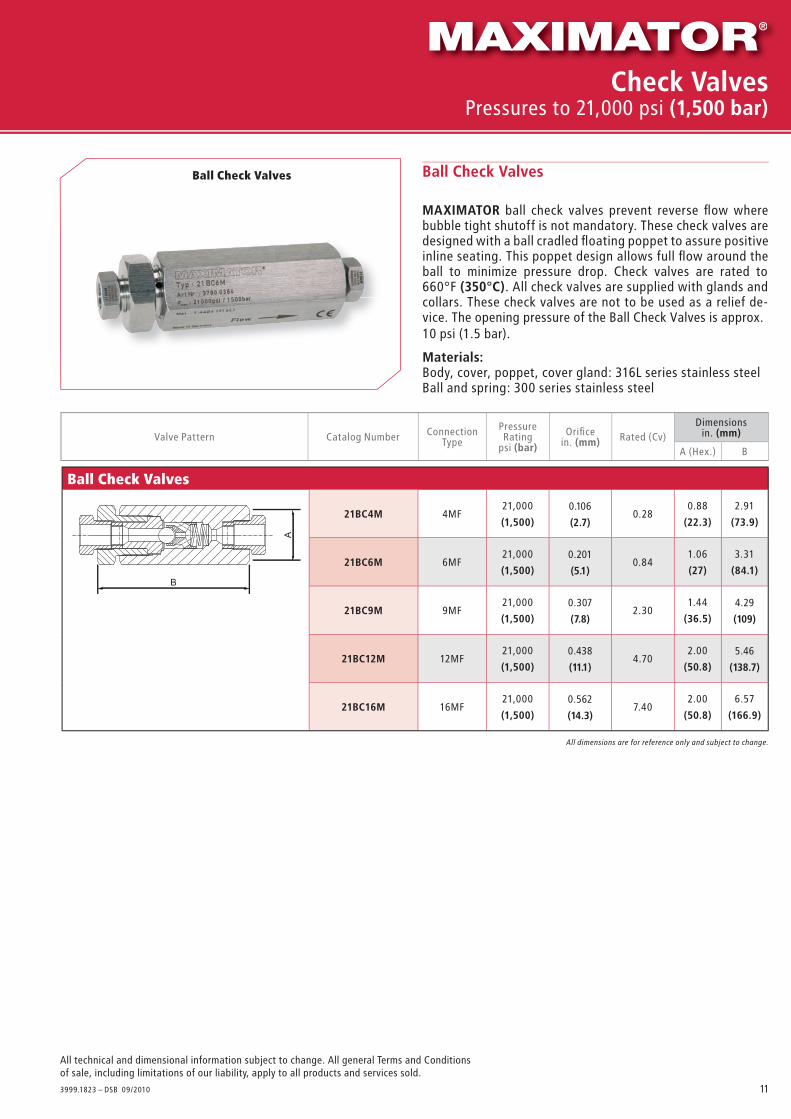
Ball Check Valves
MAXIMATOR ball check valves prevent reverse fl ow where bubble tight shutoff is not mandatory. These check valves are designed with a ball cradled fl oating poppet to assure positive inline seating. This poppet design allows full fl ow around theball to minimize pressure drop. Check valves are rated to 660°F (350°C). All check valves are supplied with glands and collars. These check valves are not to be used as a relief de-vice. The opening pressure of the Ball Check Valves is approx. 10 psi (1.5 bar).
Materials Body, cover, poppet, cover gland: 316L series stainless steelBall and spring: 300 series stainless steel
Ball Check Valves
Valve Pattern Catalog Number Connection Type
Pressure Rating
psi (bar)
Orifi cein. (mm) Rated (Cv)
Dimensions in. (mm)
A (Hex.) B
All dimensions are for reference only and subject to change.
Ball Check Valves
21BC4M 4MF21,000
(1,500)0.28
0.88
(22.3)
2.91
(73.9)
21BC6M 6MF21,000
(1,500)0.84
1.06
(27)
3.31
(84.1)
21BC9M 9MF21,000
(1,500)2.30
1.44
(36.5)
21BC12M 12MF21,000
(1,500)4.70
2.00
(50.8)
21BC16M 16MF21,000
(1,500)7.40
2.00
(50.8)
6.57
(166.9)
B
A
Check ValvesPressures to 21,000 psi (1,500 bar)
0.106
(2.7)
0.201
(5.1)
0.307
(7.8)
4.29
(109)
0.438
(11.1)
5.46
(138.7)
0.562
(14.3)

12
All technical and dimensional information subject to change. All general Terms and Conditions of sale, including limitations of our liability, apply to all products and services sold.
3999.1823 – DSB 09/20
Cup-Type Line Filters21CF4M-5
21,000
(1,500)
54MF
0.82
(530)
2.38
(60.5)
2.87
(72.9)
0.88
(22.3)21CF4M-30 3021CF4M-56 5621CF6M-5
21,000
(1,500)
56MF
0.82
(530)
2.83
(71.8)
3.35
(85.1)
1.06
(27)21CF6M-30 3021CF6M-56 5621CF9M-5
21,000
(1,500)
59MF
1.55
(1,000)
3.63
(92.2)
4.33
(110)
1.44
(36.5)21CF9M-30 3021CF9M-56 5621CF12M-5
21,0005
12MF6.14
(3,960)
5.75
(146)
6.57
(166.9)
2.00
(50.8)21CF12M-30 3021CF12M-56 5621CF16M-5 21,000
(1,500)
516MF
6.14
(3,960)
5.75
(146)
6.57
(166.9)
2.00
(50.8)21CF16M-30 3021CF16M-56 56
Dual-Disc Line Filters
MAXIMATOR dual-disc line fi lters are used to fi lter process fl uids in high pressure systems. This design helps remove the large particles fi rst through a coarse primary disc, which then allows a secondary disc to provide a smaller micron fi ltration. These fi lter elements are designed to withstand pressure surges without cracking, fl aking, or rupturing. Filter elements come standard in the following micron sizes: 5/8, 8/30, 30/56 (secondary/primary). Filters are rated for temperatures -60˚F to 660˚F (-50°C to 350°C). All line fi lters come with glands and collars.
MaterialsBody cover, cover gland: 316L series stainless steel Element: 316 stainless steel
Cup-Type Line Filters
MAXIMATOR cup-type line fi lters are used when maximum fi ltration surface area and a single micron size element is preferred. This design increases the fi lter area as much as 6 times the area of the disc type fi lter, and will permit higher fl ow rates with a lower pressure drop, and longer intervals between element changes. Filter elements come standard in 5, 30, or 56 micron sizes and are easily replaced. Filters are rated for temperatures -60˚F to 660˚F (-50°C to 350°C). All line fi lters come with glands and collars.
Materials: Body, cover, cover gland: 316L series stainless steel Element: 316 stainless steel
Dual-Disc Line Filters
Cup-Type Line Filters
It is recommended that all fl uids entering a high pressure system be thoroughly cleaned. Maximator fi lters are designed to remove small amounts of process particles. Pressure differential should not exceed 1000 psi across the fi lter elements.
Catalog Number Pressure Rating psi (bar)
Orifi ce in. (mm) Micron Size Connection Type Filter Element
Area in.2 (mm)2
Dimensions in. (mm)
A B C (Hex.)
Dual-Disc Line Filters21DF9M - 5/8 21,000
(1,500)
5/89MF
0.25
(160)
2.68
(68.1)
4.96
(126)
1.44
(36.5)21DF9M - 8/30 8/30
21DF9M - 30/56 30/56
All dimensions for reference only and are subject to change.
A
B
C
A
B
C
Line FiltersPressures to 21,000 psi (1,500 bar)
0.265
(6.5)
0.106
(2.7)
0.201
(5.1)
0.307
(7.8)
(1,500)
0.438
(11.1)
0.562
(14.3)

13
All technical and dimensional information subject to change. All general Terms and Conditions of sale, including limitations of our liability, apply to all products and services sold.
3999.1823 – DSB 09/2007
21SH4M 4MF21,000
(1,500)
20
(30)
1.06
(27)
0.88
(22.3)
2.48
(63)
0.109
(2.8)
0.250
(6.3)
21SH6M 6MF21,000
(1,500)
30
(40)
1.06
(27)
0.88
(22.3)
2.72
(69.1)
0.203
(5.1)
0.250
(6.3)
21SH9M 9MF21,000
(1,500)
55
(75)
1.06
(27)
0.88
(22.3)
2.51
(63.7)
0.250
(6.3)
21SH12M 12MF21,000
(1,500)
90
(120)
1.19
(30.2)
0.88
(22.3)
2.72
(69.1)
0.250
(6.3)
21SH16M 16MF21,000
(1,500)
150
(200)
1.44
(36.6)
0.88
(22.3)
2.72
(69.1)
0.250
(6.3)
MAXIMATOR safety head assemblies are used to provide over-pressure protection to high pressure systems. These safety head assemblies are to be used with the appropri-ate 1/4” angular rupture disc listed in the chart below.
Safety Head AssemblyCatalog Number
without Disc
Fits Connection Type
Pressure Rating psi (bar)
Body Torque ft - lbs.(Nm)
Dimensions in. (mm)
A(Hex.)
B(Hex.)
C(LG.)
D(I.D.)
E(I.D.)
Safety Head Assembly
All dimensions for reference only and are subject to change.
Safety Head AssemblyPressures to 21,000 psi (1,500 bar)
0.255
(6.5)
0.255
(6.5)
0.255
(6.5)
Repture disc
(not included)
Body
Hold-down
ring Hold-down
nut
3/8 NPT
Female
connection

14
All technical and dimensional information subject to change. All general Terms and Conditions of sale, including limitations of our liability, apply to all products and services sold.
3999.1823 – DSB 09/2010
1/4" Angular Rupture Discs
RD-55005,335 - 5,830
(367.9-402.1)
RD-60005,820 - 6,360
(401.4-438.6)
RD-65006,305 - 6,890
(434.8-475.2)
RD-70006,790 - 7,420
(468.3 - 511.7)
RD-75007,275 - 7,950
(501.7-548.3)
RD-80007,760 - 8,480
(535.2 - 584.8)
RD-85008,245 - 9,010
(568.6 - 621.4)
RD-90008,730 - 9,540
(602.1 - 657.9)
RD-95009,215 - 10,070
(635.5 - 694.5)
RD-100009,700 - 10,600
(669 - 731)
RD-1100010,670 -11,660
(735.9 - 804.1)
RD-1000970 - 1,060
(66.9-73.1)
RD-12001,164 - 1,272
(80.3-87.7)
RD-15001,455 - 1,590
(99.7-109.7)
RD-17501,697 - 1,855
(117-127.9)
RD-20001,940 - 2,120
(133.8-146.2)
RD-25002,425 - 2,650
(167.2-182.8)
RD-30002,910 - 3,180
(200.7-219.3)
RD-35003,395 - 3,710
(234.1-255.9)
RD-40003,880 - 4,240
(267.6-292.4)
RD-45004,365 - 4,770
(301-329)
RD-50004,850 - 5,300
(334.5-365.5)
RD-1200011,640 - 12,720
(802.8 - 877.2)
RD-1300012,610 - 13,780
(869.7 - 950.3)
RD-1400013,580 - 14,840
(936.6 - 1023.4)
RD-1500014,550 - 15,900
(1,003.4 - 1,096.6)
RD-1600015,520 - 16,960
(1,070.3 - 1,169.7)
RD-1700016,490 - 18,020
(1,137.2 - 1,242.8)
RD-1800017,460 - 19,080
(1,204.1 - 1,315.9)
RD-1900018,430 - 20,140
(1,271 - 1,389)
RD-2000019,400 - 21,200
(1,337.9 - 1,462.1)
RD-2100020,370 - 22,260
(1,404.8 - 1,535.2)
RD-2200021,340 - 23,320
(1,471.7 - 1,608.3)
Catalog Number Pressure rangepsi (bar)Catalog Number Pressure range
psi (bar)Catalog Number Pressure rangepsi (bar)
Rupture Discs are individually packed and marked type plate.
1/4“ angular seat rupture discs are designed to be used with the safety
head assemblies that are shown above. Minimum rupture disc pressure
ratings should be at least 110% of system operating pressure. The
standard material is stainless steel. The pressure ranges indicated in
the table below are at room temperature (72°F).Other materials and
pressure ranges are available upon request.