
Medium Intensity Installation Manual - Dialight No: 9100-127-2967-99, Rev. B Release Date: 11/20/17...
32
Document No: 9100-127-2967-99, Rev. B Release Date: 11/20/17 1501 Route 34 South, Farmingdale, NJ 07727 Tel: (732) 919-3119 Fax: (732) 751-5778 www.dialight.com DO NOT let any supply cords touch hot surfaces higher than cord ratings. DO NOT mount near gas or electric heaters Equipment should be mounted in locations and at heights where it will not be subjected to tampering by unauthorized personnel. The use of accessory equipment not recommended by the manufacturer may cause unsafe conditions. DO NOT use this equipment for other than intended use. DO take pictures: Installation Photos Required for Warranty Coverage. (All electrical connections, bonding, system support and grounding) DO NOT look into the Infrared (IR) LEDs. These five IR LEDs on top of the unit (if applicable) will not appear to be ON, but can be verified using most digital cameras. SAVE THESE INSTRUCTIONS!! The operation and maintenance must be carried out by authorized personnel. Repairs and Installation must only be carried out by a qualified electrician. Only genuine Dialight replacement parts must be used when unforeseen repairs are required. Observe the national safety rules and regulations during installation! Earth Grounding is required throughout the install process. Failure to do so could void all warranties! No alterations should be done without agreement from Dialight Corp. Alterations other than written in this manual will void all warranties. Medium Intensity Installation Manual READ AND FOLLOW ALL SAFETY INSTRUCTIONS
Transcript of Medium Intensity Installation Manual - Dialight No: 9100-127-2967-99, Rev. B Release Date: 11/20/17...

Document No: 9100-127-2967-99, Rev. B
Release Date: 11/20/17
1501 Route 34 South, Farmingdale, NJ 07727
Tel: (732) 919-3119 Fax: (732) 751-5778 www.dialight.com
DO NOT let any supply cords touch hot surfaces higher than cord ratings.
DO NOT mount near gas or electric heaters
Equipment should be mounted in locations and at heights where it will not be subjected to tampering by unauthorized personnel.
The use of accessory equipment not recommended by the manufacturer may cause unsafe conditions.
DO NOT use this equipment for other than intended use.
DO take pictures: Installation Photos Required for Warranty Coverage. (All electrical connections, bonding, system support and grounding)
DO NOT look into the Infrared (IR) LEDs. These five IR LEDs on top of the unit (if applicable) will not appear to be ON, but can be verified using most digital cameras.
SAVE THESE INSTRUCTIONS!!
The operation and maintenance must be carried out by authorized personnel.
Repairs and Installation must only be carried out by a qualified electrician.
Only genuine Dialight replacement parts must be used when unforeseen repairs are required.
Observe the national safety rules and regulations during installation!
Earth Grounding is required throughout the install process. Failure to do so could void all warranties!
No alterations should be done without agreement from Dialight Corp. Alterations other than written in this manual will void all warranties.
Medium Intensity Installation Manual READ AND FOLLOW ALL SAFETY INSTRUCTIONS

Document No: 9100-127-2967-99, Rev. B
Release Date: 11/20/17
1501 Route 34 South, Farmingdale, NJ 07727
Tel: (732) 919-3119 Fax: (732) 751-5778 www.dialight.com
Introduction: This manual is for installing the Dual Strobe system or Dual Strobe + IR (Infrared) system. Covered in this manual is the following information.
Notice and warnings
Environmental Specifications
Installing the Controller and the pre drilled holes
Dimensions of the Controller
Securing the cables to the structure
Connection of either AC or DC input voltages
Connection of the Side lights and calibration
Photocell connections
Flash Head connections
Proper bonding of the Strobe cable
Mounting the Flash Head Not included in this manual: Refer to the quick start manual for the below information
System overview
Installation Tips and requirements
System Descriptions
RS485 Communication Connections
Installing the RS485 to additional power supplies
Controller layouts
Navigating the LCD Display o LCD startup display screens o Setup Screens (Configuration) o Main Menu Screens o Manual Lighting inspection test
Controller Status LED’s Dry contact connections Controller electrical Parameters Resetting, ext. sync option, and serial numbers Replacement part numbers Display Events and Alarm Descriptions
Alarm list and possible causes

Document No: 9100-127-2967-99, Rev. B
Release Date: 11/20/17
1501 Route 34 South, Farmingdale, NJ 07727
Tel: (732) 919-3119 Fax: (732) 751-5778 www.dialight.com
Notice and Warnings:
This manual contains important information regarding the proper installation, operation,
and maintenance of this product. Before using the product, read and understand all
instructions, cautions, notes and warnings, as well as all of the labels affixed to the
product. Failure to do so could result in personal injury or damage to equipment and/or
void the product warranty.
FAILURE TO LEAVE THE ENCLOSURES FREE FROM DEBRIS UPON COMPLETION OF
INSTALLATION MAY CAUSE SHORT CIRCUITS AND VOID THE SYSTEM WARRANTY
FAILURE TO TIGHTEN DOWN CLAMP WASHERS WILL MAKE INTERNAL COMPONENTS
VULNERABLE TO SURGE OR LIGHTNING DAMAGE AND VOID THE SYSTEM WARRANTY
FAILURE TO PROPERLY BOND THE EARTH GROUND WIRE TO THE JUNCTION BOX WILL
RESULT IN EVENTUAL LIGHTNING DAMAGE OF THIS SYSTEM. TO AVOID WARRANTY
NULLIFICATION, FOLLOW THE DIRECTIONS IN THEIR ENTIRETY.
CAUTION: ONLY APPROVED PHOTOCELLS CAN BE USED WITH THIS SYSTEM
WARNING: FAILURE TO PROPERLY BOND THE FLASH HEADS AND POWER SUPPLY
ENCLOSURES TO THE TOWER STRUCTURE WILL RESULT IN EVENTUAL LIGHTNING
DAMAGE OF THIS SYSTEM. THE SYSTEM’S WARRANTY SHALL BE VOID IF ALL FLASH
HEADS AND POWER SUPPLY ENCLOSURES ARE NOT PROPERLY BONDED TO THE TOWER
STRUCTURE. TO AVOID WARRANTY NULLIFICATION, FOLLOW THE DIRECTIONS IN
THEIR ENTIRETY.
CAUTION: NEVER LOOK AT THE FRONT OF A FLASH HEAD WHILE THE SYSTEM IS
ENERGIZED. THE FLASH HEAD COULD START FLASHING CAUSING TEMPORARY
BLINDNESS WHICH WOULD BE DANGEROUS AT HIGH ELEVATIONS.
FAILURE TO SET UP SYSTEM CORRECTLY DURING START UP WILL RESULT IN THE
TOWER HAVING TO BE CLIMBED AGAIN TO PERFORM TROUBLESHOOTING.
DO NOT LOOK AT THE INFRARED (IR) LEDs WHILE THE UNIT IS ON. THESE 5 IR LEDs
ON THE TOP OF THE UNIT (IF APPLICABLE) WILL NOT APPEAR TO BE ON, BUT CAN BE
VERIFIED USING MOST DIGITAL CAMERAS.

Document No: 9100-127-2967-99, Rev. B
Release Date: 11/20/17
1501 Route 34 South, Farmingdale, NJ 07727
Tel: (732) 919-3119 Fax: (732) 751-5778 www.dialight.com
USE PROPER METHODS OF LIFTING AND CARRYING TO PROTECT AGAINST INJURY.
FOLLOW THE RECOMMENDATIONS BELOW TO ENSURE ENCLOSURES ARE HANDLED
IN A SAFE MANNER:
BASED ON FACILITY SAFETY REQUIREMENTS DETERMINE IF THE ENCLOSURE
REQUIRES TEAM LIFTING
BEND AT THE KNEES AND MAKE SURE YOUR BACK IS STRAIGHT BEFORE
LIFTING
LIFT WITH YOUR LEGS AND NOT YOUR BACK
KEEP THE ENCLOSURE CLOSE TO YOUR BODY WHILE CARRYING
KEEP YOUR BACK STRAIGHT WHEN LOWERING
Environmental Specifications Operating Temperature Range: -40°C to +55°C
IP66, Suitable for outdoor use
Pollution degree: P1
Equipment is intended to be installed at an altitude of 2000m or less

Document No: 9100-127-2967-99, Rev. B
Release Date: 11/20/17
1501 Route 34 South, Farmingdale, NJ 07727
Tel: (732) 919-3119 Fax: (732) 751-5778 www.dialight.com
System Overview
POWER SUPPLY / CONTROLLER
L-865 / L-864 PHOTOCELL GPS
(OPTIONAL)
RTO L-810
QTY. 3
TYPICAL TOWER CONFIGURATION
E1
AC

Document No: 9100-127-2967-99, Rev. B
Release Date: 11/20/17
1501 Route 34 South, Farmingdale, NJ 07727
Tel: (732) 919-3119 Fax: (732) 751-5778 www.dialight.com
Installation Tips and Requirements The D1xW-CTR-4x9 Power Supply / Controller are housed in a NEMA4X rated outdoor enclosure and can be installed either outside or in a shelter. If installed outside on or near the structure; the installer must consider water ingress and proper earth grounding to reduce the risk of premature failures. For the Mains cable, it is recommended that the electrician or installer calculate the wire requirements based on the system being installed. It is recommended that no install utilizes less than 14AWG 600V cable with at least a 90ºC temperature rating. See electrical parameters in the quick start manual for further information. It is recommended that the lighting system be on its own breaker adequately rated for the system’s power consumption. The breaker MUST be rated for at least 20% higher than the systems total current draw. During installation proper grounding techniques must be utilized. The system has built in Lightning and RF immunity at each section, but for it to be effective proper ground connection techniques must be used. Cable specifications NOTE: Cables for monitoring and AC or DC Input cable are not supplied. Specification for Input cable: Requires 3 conductors for both the AC input and the DC input version. Earth Ground is required in the controllers. A minimum of 14AWG is to be used. Bonding ground wire when required is to be 6AWG Individual wires can be used but must be routed through conduit or seal tight. Specification for RS485 Cable: Requires 3 conductors of 18AWG, drain wire plus a braid for adequate grounding. NOTE: Only required for systems that have more than one D1xW such as an E2 structure. Specification for Photocell Cable: 3 conductors of 18AWG. Colors are Red, Black and Green Specification for 48Vdc L810 Side Marker Cable: 3 conductors of 18AWG For structures that require more than 2 levels of side lights larger diameter cable is required. Colors are Red, Black and Green Specification for AC L810 Side Marker Cable: 3 conductors of 16AWG For structures that require more than 2 levels of side lights larger diameter cable is required. Colors are Black, White and Green

Document No: 9100-127-2967-99, Rev. B
Release Date: 11/20/17
1501 Route 34 South, Farmingdale, NJ 07727
Tel: (732) 919-3119 Fax: (732) 751-5778 www.dialight.com
Specification for the 4 conductor Flash head cable 4 Conductors of 14 AWG with foil and braid. 630feet maximum distance Colors are Red, Red with black stripe, White and White with black stripe NOTE: Stripes are always for the negative connection NOTE: Failure to meet any of the above cable requirements could void all factory warranties. If in doubt please contact your sales representative or www.Dialight.com. All cables that extend up the structure must be adequately secured to the structure with the use of ¾” filament tape and 2” black all weather tape. NOTE: The cable should be ran on the inside of the structure leg when possible. NOTE: Cables that run along the structure require taping/securing and must be done in 5’ increments.

Document No: 9100-127-2967-99, Rev. B
Release Date: 11/20/17
1501 Route 34 South, Farmingdale, NJ 07727
Tel: (732) 919-3119 Fax: (732) 751-5778 www.dialight.com
Typical Triangular Tower Configuration of an A1 or E1 System

Document No: 9100-127-2967-99, Rev. B
Release Date: 11/20/17
1501 Route 34 South, Farmingdale, NJ 07727
Tel: (732) 919-3119 Fax: (732) 751-5778 www.dialight.com
Typical Wiring Diagram for a E1 or A1 Structure NOTE: The flash head cable does NOT have any splices

Document No: 9100-127-2967-99, Rev. B
Release Date: 11/20/17
1501 Route 34 South, Farmingdale, NJ 07727
Tel: (732) 919-3119 Fax: (732) 751-5778 www.dialight.com
Tower Configurations for installing side lights Typically triangular towers require 3 side lights (A3) Square towers typically require 4 side lights. NOTE: For 4 side lights the junction may require an additional hole to be drilled. Each level of the side lights requires 1 junction box at the light level (B)
L810 Side light Junction Boxes in the Installation As shown in Detail “B” above in ‘Typical Triangular Tower Configuration of an E1 System’. Junction boxes are only used for connecting the side lights. There are no electronics located in the boxes. All junction boxes must be grounded and secure to the structure and cannot be floating off the structure.
WARNING: When bonding to the structure, paint and or debris must be cleaned.
WARNING: When grounding to a painted structure the paint must be removed.
Additional ground cable using 6AWG solid can be added from the Junction box enclosure to the structure. Not supplied
Document No: 9100-127-2967-99, Rev. B
Release Date: 11/20/17
1501 Route 34 South, Farmingdale, NJ 07727
Tel: (732) 919-3119 Fax: (732) 751-5778 www.dialight.com
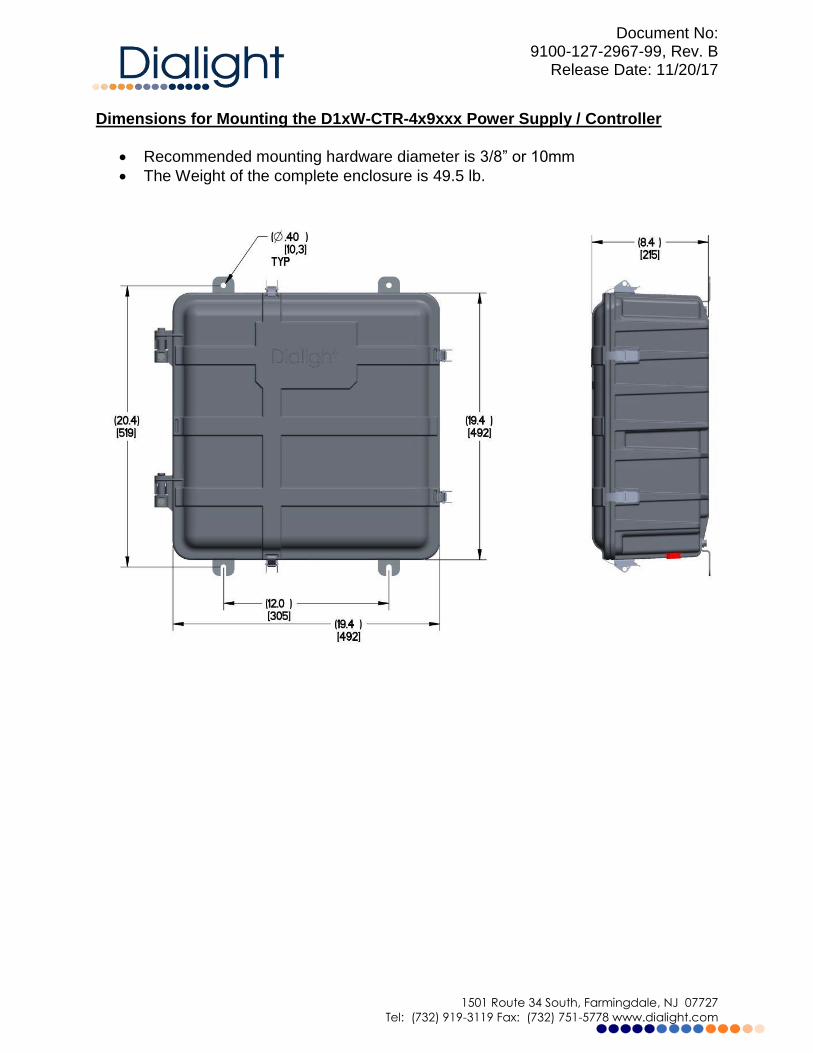
Dimensions for Mounting the D1xW-CTR-4x9xxx Power Supply / Controller
Recommended mounting hardware diameter is 3/8” or 10mm
The Weight of the complete enclosure is 49.5 lb.

Document No: 9100-127-2967-99, Rev. B
Release Date: 11/20/17
1501 Route 34 South, Farmingdale, NJ 07727
Tel: (732) 919-3119 Fax: (732) 751-5778 www.dialight.com
Recommended Locations for Cable Entry: The enclosures are supplied with factory drilled holes. All holes not used must be properly sealed. To maintain water ingress protection all additional holes should located at the bottom side of the enclosure. NOTE: Dimensions are suited for ¾ inch cord grips or seal tight. Proper installation must be conducted to prevent moisture entering the enclosure. NOTE: Additional Ground cables can be added either from the mounting feet or inserted to the ground terminal block located in the power supply. Cables are not supplied.
NOTE: If there is existing AC and RS485 communication in the vicinity of the Base Controller installation then these cables can be used if they meet the requirements in this guide.
NOTE: Multiple grounding points are provided in the enclosure for protective and functional Earth/Ground connections.
NOTE: When installing systems E1+1 or larger than daisy chaining the AC or DC input is preferred.
NOTE: When installing systems E1+1 or larger than daisy chaining the RS485 is required.
Detail View of D1xW-CTR-4x9xxx Power Supply / Controller:
MARKER PHOTOCELL FLASH RS485 DRY MAINS
LIGHTS HEAD CONTACTS CONNECTIONS

Document No: 9100-127-2967-99, Rev. B
Release Date: 11/20/17
1501 Route 34 South, Farmingdale, NJ 07727
Tel: (732) 919-3119 Fax: (732) 751-5778 www.dialight.com

Document No: 9100-127-2967-99, Rev. B
Release Date: 11/20/17
1501 Route 34 South, Farmingdale, NJ 07727
Tel: (732) 919-3119 Fax: (732) 751-5778 www.dialight.com
Securing Cables to the Structure It is vitally important for lightning protection that all cabling running up the structure be secured using the following steps. This is the absolute minimum required. Additional points of securing should be added as required. Securing points must be done in 5’ increments with the first point being the lowest cross member or lowest point on the structure. See items “O” and “M” above in ‘Typical Triangular Tower Configuration of an E1 System’. NOTE: All cables must be done the same way. NOTE: If there is a build up of dirt in the securing area it should be cleaned before applying the tape. NOTE: Tape should be applied in an overlapping method to provide maximum protection and support for the cable. NOTE: For legs that are NOT circular, special care must be taken when securing the cabling. NOTE: For Hot AM towers all cables must be installed in metal conduit or installed with TECK cable. Contact www.dialight.com for additional installation information. WARNING: Splices are not allowed between the Power supply and the flash head. If junction boxes are required by the site manager pre-approval by Dialight authorized personnel is required.
Securing the Flash head cable to the Tower
1: Wrap 2 or 3 bands of the Black weather tape around the leg 2: Hold the cable in place while wrapping 2 or 3 wraps of filament tape. This provides the strength to secure the cable. 3: Wrap 4 or 5 bands of the weather tape over the filament tape to make a weather tight bond

Document No: 9100-127-2967-99, Rev. B
Release Date: 11/20/17
1501 Route 34 South, Farmingdale, NJ 07727
Tel: (732) 919-3119 Fax: (732) 751-5778 www.dialight.com
Input Power connections requirements Refer to detail “A” in Detail View of D1XwCTR4x9xxx Power Supply / Controller The terminal block can accommodate (16AWG minimum to 10AWG maximum). NOTE: If installed outdoors water ingress must be considered. NOTE: Cable supplied is wet location and UV resistant but should be confirmed by reading the outer jacket of the cable. If in doubt please contact www.Dialight.com. WARNING: To ensure that moisture does not enter the enclosure, cable loops must be added to all the exposed cables. These are to be 2-3 complete circles of approx. 6” - 12” diameters. Additional can be added as required by the installer. When seal tight, liquid tight, conduit or Teck cable is being used cable loops are not required. WARNING: If conduit is being used to run the cables into the enclosure than the conduit should be tilted slightly downwards and away from the enclosure to avoid condensation draining into the enclosure. A drain adapter could also be added to the conduit. WARNING: A drain enclosure with a drain port must be added to any vertical runs of conduit. The drain box must be located at the lowest point of the install. Any right angle connections of conduit should flow towards this enclosure. The enclosure MUST be grounded to the structure. WARNING: If TECK cable is being used then adequate draining MUST be added during the installation process. NOTE: If there is existing AC in the vicinity of the installation location then these cables can be used if they meet the recommendations in this guide. The installer MUST thoroughly check the cable for damage that would shorten the life of the system. It is highly recommended that the bare wires be cut off until clean copper is exposed before connecting to the system. NOTE: Multiple grounding points and clamps are provided in the enclosure for protective and functional Earth/Ground connections. NOTE: When installing systems E1+1 or larger than daisy chaining the AC or DC input is preferred.

Document No: 9100-127-2967-99, Rev. B
Release Date: 11/20/17
1501 Route 34 South, Farmingdale, NJ 07727
Tel: (732) 919-3119 Fax: (732) 751-5778 www.dialight.com
Connection of AC Input Power Input cable and is NOT supplied with the system Related part numbers: D1Xw-CTR-409xxx
1: The AC connection requires 3 conductors. Live, Neutral and Earth Ground Individual wires can be used but must be fed through seal tight or conduit. WARNING: Floating Neutrals are not permissible within the wiring of the system and the installer must verify the connections. This will “Void” all warranties and cause system failure during turn on. WARNING: Earth ground connection is required to provide safety and proper operation of the system. WARNING: There can be no more than 305Vac measured from Live to Earth ground or Live to Neutral on TB1. This must be measured before powering up the system. NOTE: The load and voltage loss of the cable must be quantified before selecting the cable size requirements. See electrical specifications for details.

Document No: 9100-127-2967-99, Rev. B
Release Date: 11/20/17
1501 Route 34 South, Farmingdale, NJ 07727
Tel: (732) 919-3119 Fax: (732) 751-5778 www.dialight.com
Connection of 48 Vdc input cable Input cable is NOT supplied with the system Related part numbers: D1Xw-CTR-449xxx
1: The 48 VDC connections require 3 conductors. +48, -48 and Earth Ground Individual wires can be used but must be fed through seal tight or conduit. WARNING: Failure to use properly rated cable will VOID all warranties and could cause premature failures. The D1Xw-CTR-449xxx has been designed to accept any of the following connection options. Individual wires can be used but must be fed through seal tight or conduit.
NOTE: Additional Earth ground may be included in the installation process and MUST be connected to the Aluminum plate located inside the enclosure.
Earth
Ground
+
Battery
-
+
Battery
-
+
-
TB 1
Option 2
+
-
TB 1
Earth Ground Ground
+
Battery -
+
Battery
-
Option 1

Document No: 9100-127-2967-99, Rev. B
Release Date: 11/20/17
1501 Route 34 South, Farmingdale, NJ 07727
Tel: (732) 919-3119 Fax: (732) 751-5778 www.dialight.com
WARNING: If any of the above options are not suited for the installation then contact your local sales representative or supplier of the system. Located at the bottom right hand side of the enclosure is the terminal block required for connecting the input voltage.
+
-
TB 1
+
Battery -
+
Battery -
Option 4
+
-
TB 1
Earth Ground
+
Battery -
+
Battery -
Option 3
Earth Ground

Document No: 9100-127-2967-99, Rev. B
Release Date: 11/20/17
1501 Route 34 South, Farmingdale, NJ 07727
Tel: (732) 919-3119 Fax: (732) 751-5778 www.dialight.com
RS485 Communication Connection Definitions NOTE: The below is common between all the controllers covered in the manual. The connection of the RS485 cable is vitally important to the operation of the system. This connection provides all the events and alarms to the Master controller that is being used with the installation. Factory connected wiring color code: Boards are Labeled Description Color Code
Label “A” Communications “A” Grey
Common Common for RS485 Yellow
Label “B” Communications “B” Blue
RS485 cable supplied by Dialight consists of 3 conductors, a drain wire, foil shield and braid. Install Cable Connected to Description Color Code
Conductor 1 Label “A” Communications “A” Grey
Conductor 2 Common Common for RS485 Yellow
Conductor 3 Label “B” Communications “B” Blue
Drain wire Ground stud Ground Bare wire
Foil Shield and Braid
Clamping terminal Ground Connected when cable enters the
enclosure and must be secured to the
plate
NOTE: Refer to quick start manual for connecting daisy chaining RS485 communications cable

Document No: 9100-127-2967-99, Rev. B
Release Date: 11/20/17
1501 Route 34 South, Farmingdale, NJ 07727
Tel: (732) 919-3119 Fax: (732) 751-5778 www.dialight.com
Connection of the Side Marker Lights (L810’s or RTO’s) to the Marker Light Monitor Board
CONNECTION OF RTO’s TO TERMINAL BLOCKS IN MAIN CONTROLLER Connect the side marker lights to the designated terminals blocks in the bottom left hand side of the enclosure as shown in the diagram above.
CONNECTION OF RTO TERMINAL BLOCKS TO MARKER LIGHT MONITOR BOARD IN MAIN CONTROLLER
These terminal blocks were factory wired to the Marker Light Monitor Board in the Controller as shown in the diagram above. Connections were made to J6 (+48V OUT)
SIDE MARKER
LIGHT CONNECTIONS
FACTORY WIRED
TO TERMINAL
BLOCKS

Document No: 9100-127-2967-99, Rev. B
Release Date: 11/20/17
1501 Route 34 South, Farmingdale, NJ 07727
Tel: (732) 919-3119 Fax: (732) 751-5778 www.dialight.com
and J1 (RETURNS, negative -) of the Marker Light Monitor Board from the terminal blocks. WARNING: Low Voltage L810’s are to be used for connecting to these ports. WARNING: Green earth ground wires MUST be connected and typically all connected together. +48V OUT Connections:
Pin 1 +48Vdc Voltage to L810 or Tier
Pin 2 +48Vdc Voltage to L810 or Tier
Pin 3 +48Vdc Voltage to L810 or Tier
Pin 4 +48Vdc Voltage to L810 or Tier
NOTE: A single Pin connection can power all L810’s. Return Connections:
Pin 1 -48Vdc For Monitoring Tier 1 or individual 810
Pin 2 -48Vdc For Monitoring Tier 2 or individual 810
Pin 3 -48Vdc For Monitoring Tier 3 or individual 810
Pin 4 -48Vdc For Monitoring Tier 4 or individual 810
NOTE: A maximum of 1.2 amps can be monitored through each pin connection. Manual Calibration of Side Lights See the quick start manual auto calibration option Follow these steps to calibrate the Marker Light Monitor Board located in the Controller. These steps will allow the system to properly identify, power, and monitor the RTO side markers.
- STEP 1 – CLEAR the Marker Light Monitor Board by holding down buttons SW1-4 at same time.
- STEP 2 – FAULT LED’s #1-4 will light up red. - STEP 3 – Press “RESET” button (SW7). - STEP 4 – Each output will auto configure within 15 seconds. - STEP 5 – Verify Each output is correct:
Green “OK” LED will illuminate green if RTO output is present.
“OK”, “FAULT”, and “CAL” LED’s will be off if RTO output is NOT present

Document No: 9100-127-2967-99, Rev. B
Release Date: 11/20/17
1501 Route 34 South, Farmingdale, NJ 07727
Tel: (732) 919-3119 Fax: (732) 751-5778 www.dialight.com
MARKER LIGHT MONITOR BOARD SHOWING BUTTONS AND SWITCH FOR
CONFIGURATION AND CALIBRATION
NOTE: Each calibration port has been designed to accurately handle up to four L810’s simultaneously;
thus have a maximum of sixteen L810’s. If additional L810’s are required, contact www.Dialight.com
Wiring for the +48Vdc L810 Side Markers: WARNING: Ground connection left out for clarity but must be connected during the installation. NOTE: Dialight’s 48VDC versions of the L810 have factory installed wires that are Red, Black and Green. NOTE: Dialight’s AC versions of the L810 have Black, White and Green; and cannot be used.

Document No: 9100-127-2967-99, Rev. B
Release Date: 11/20/17
1501 Route 34 South, Farmingdale, NJ 07727
Tel: (732) 919-3119 Fax: (732) 751-5778 www.dialight.com
Level monitoring does require visual inspection for a single faulty light. The controller will indicate an event plus a LED AL7 will illuminate for a faulty light. Connections 1, 2, 3 are to be used for each level of side lights installed. Typically 1 should be the north leg. A maximum of four L810’s can be individually monitored.
Level monitoring using 3 conductors allows for the system to know what level the fault is on but visual inspection is required to verify which light is faulty.
Level Monitoring Using 3 conductors Red for +48Vdc Black for level 1 Brown for level 2
+48Vdc
-48Vdc return
-48Vdc

Document No: 9100-127-2967-99, Rev. B
Release Date: 11/20/17
1501 Route 34 South, Farmingdale, NJ 07727
Tel: (732) 919-3119 Fax: (732) 751-5778 www.dialight.com
Photocell Connection: Dialight P/N D256-6000PEC NOTE: The photocell contains its own manual and should be read in its entirety.
Open supplied photocell enclosure. The Photocell requires 3 connections to be made to the inside of the photocell enclosure itself and 3 inside the controller.
+V = 12Vdc (supplied from controller) SIG. IN = Sense voltage relayed to controller Return = Ground Cable Requirements: 3 conductor, 18AWG minimum Maximum allowable distance is 500 feet from the controller NOTE: When mounting the Photocell it must face north and be placed in a location without obstructions. The photocell comes supplied with one end threaded for ¾” NPT conduit, which is recommended for installing the photocell. NOTE: If a cable is to be used than the cable MUST have either a shield or braid that is properly connected to body of the photocell and to the enclosure of the controller it is being installed to. Failure to properly ground, or use a cable without the shield or braid will void all warranties and the product could be subject to premature failures.
J4 of Marker light monitor board located inside of controller

Document No: 9100-127-2967-99, Rev. B
Release Date: 11/20/17
1501 Route 34 South, Farmingdale, NJ 07727
Tel: (732) 919-3119 Fax: (732) 751-5778 www.dialight.com
Flash Head and Power Supply Cable Connections 4 Conductor Connections The Power Supply and the Flash Head have the same surge/terminal connections so the information below will be used for connecting in the Flash Head and in the Power Supply. NOTE: This is the only connection in the Flash Head pedestal that is required. NOTE: WARNING: If the cable is not color coded or numbered the instructions state the installer must take notes of wiring to ensure that both the Flash Head and Power supply get wired the same. If for example wire 1 is inserted in to location 4 by mistake severe damage could result to the LED’s in the flash head. This will VOID all warranties. Pin 1 or RED in the flash head must go to Pin1 RED in the power supply and so on. NOTE: The installer must provide this information to the site manager upon completion for future reference when required
Washer/wing nut used to secure the
braid of the cable to ground Terminal block J2 for 4 conductor cable
The board is marked for the colors
Terminal block J1 is factory wired. NOTE: These should be checked to make sure they have not come out during installation or shipping

Document No: 9100-127-2967-99, Rev. B
Release Date: 11/20/17
1501 Route 34 South, Farmingdale, NJ 07727
Tel: (732) 919-3119 Fax: (732) 751-5778 www.dialight.com
J2 4 Conductor Terminal block definitions: NOTE: The Flash head and Power supply have the same protection board. Two conductors are required for the Red Beacon and two for the White Strobe. Red L864 Connections: Terminal block J2 pins 1 and 2 White L865 Connections: Terminal Block J2 pins 3 and 4 J2 pin designators Description
RED Connections (RED)
- pin 1 (Red/Black wire) RED LED’s negative (Cathode connection)
+ pin 2 (Red wire) RED LED’s positive (Anode connection)
White Connections (WHT)
- pin 3 (White/Black wire) WHITE LED’s negative (Cathode connection)
+ pin 4 (White wire) WHITE LED’s positive (Anode connection)
WARNING: Take care to connect correctly, as incorrect operation can cause damage to the driver modules or surge protection boards.
Connecting the Braid and Foil to the Clamping Ground Washers:
WARNING: It is vitally important that the braid and foil are properly connected under
the clamping washers for lightning protection. Failure to do will result in premature failures during lightning strikes.
NOTE: For commissioning the system, pictures must be taken of all the clamping
washers and the cables secured under them. 1: Run the cable through the provided strain reliefs before stripping the outer jacket in order not to fray the braiding. 2: Remove approx. 10” of the outer jacket.
WARNING: If internal braid is cut than it is required that the cable gets re-stripped to
ensure proper bonding. 3: Remove approx. 7” of the braiding for the wires to be connected to the terminal block J2.
NOTE: If the installer requires longer wires than what is proposed it will still require the
3” of braiding to be properly secured under the clamping washer. 4: A ½” piece of electrical tape can be added to the end of the braid to preventing fraying. 5: Unscrew the wing nut, place JUST the braided portion under the clamping washer, and secure tightly.
WARNING: The added electrical tape and outer insulation of the cable cannot be
under the clamp.

Document No: 9100-127-2967-99, Rev. B
Release Date: 11/20/17
1501 Route 34 South, Farmingdale, NJ 07727
Tel: (732) 919-3119 Fax: (732) 751-5778 www.dialight.com
6: Connect the 4 conductors to J2 as detailed above.
Clamping Washer Can hold 2 cables; 1 cable on each side
Ground Lug Fully tighten screws down and do pull test on wire(s) inserted.
A small piece of approx .5 inch of electrical tape can be added to end of braid to prevent to the braids from separating.
WARNING: Fully tighten wing nut down, DO NOT leave loose. Double check

Document No: 9100-127-2967-99, Rev. B
Release Date: 11/20/17
1501 Route 34 South, Farmingdale, NJ 07727
Tel: (732) 919-3119 Fax: (732) 751-5778 www.dialight.com
Connection of the 4 conductor cable to the Flash Head
NOTE: Properly connecting the braid of the cable is vitally important to prevent
damage during lightning strikes. The Surge protection board in the Flash Head is the same that is located in the controller and in the case of multiple Flash Heads such as an E2 or D2 system the power supplies will have the same surge board. Thus all wiring must be the same.
NOTE: For commissioning of the system pictures must be taken of the Flash Heads. Below is the list of the minimum required. 1: Internal wiring of the pedestal 2: Mounting to the structure 3: Bonding the pedestal to the structure 4: Any service loops 5: if there are lightning rods installed. Parts required (supplied as a Kit): E1 system
QTY Description Where used
1 Photocell Connected to controller
1 14 AWG 4 conductor cable Cable required from Controller to Flash Head
1 18 AWG 3 conductor cable Cable required for wiring side lights and Photocell
3 Side lights (L-810’s) Mounted at mid-level of structure
3 Mounting kits For mounting Side Lights and junction box
Rolls Filament tape and electrical
For securing wires to the structure
Parts required (supplied as a Kit): E2 system
QTY Description Where used
2 D1xW-C1x-x09-CVT Power supply (D1xW-PS9xx9) and Flash Head (D1xW-FHx09)
1 Photocell Connected to controller
2 RS485 comm cable For daisy chaining RS485

Document No: 9100-127-2967-99, Rev. B
Release Date: 11/20/17
1501 Route 34 South, Farmingdale, NJ 07727
Tel: (732) 919-3119 Fax: (732) 751-5778 www.dialight.com
3 14 AWG 4 conductor cable Cable required from Controller to Flash Head
1 18 AWG 4 conductor cable Cable required for wiring side lights and Photocell
3 Side lights (L-810’s) Mounted at mid level of structure
3 Mounting kits For mounting Side Lights and junction box
Rolls Filament tape and electrical
For securing wires to the structure
Parts required (supplied as a Kit): D1 system
QTY Description Where used
1 Photocell Connected to Controller
1 14 AWG 4 conductor cable Cable required from Base to Flash Head
1 18 AWG 3 conductor cable Cable required for wiring Photocell
Rolls Filament tape and electrical For securing wires to the structure
Parts required (supplied as a Kit): D2 system
QTY Description Where used
2 D1xW-PS-94x9 Power supply
1 Photocell Connected to controller
2 RS485 comm cable For daisy chaining RS485
3 14 AWG 4 conductor cable Cable required from Controller to Flash Head
1 18 AWG 3 conductor cable Cable required for wiring Photocell
Rolls Filament tape and electrical
For securing wires to the structure

Document No: 9100-127-2967-99, Rev. B
Release Date: 11/20/17
1501 Route 34 South, Farmingdale, NJ 07727
Tel: (732) 919-3119 Fax: (732) 751-5778 www.dialight.com
Mechanical Dimensions of D1RW L864/865 Flash Head
Mounting Pattern Six mounting holes are provided on the Flash Head pedestal. These mounting holes will align with most tower pedestals. The Flash Head must be installed level according to the bulls-eye level on the light engine to maintain light output in accordance with FAA requirements. NOTE: The mounting location bracket should also be level. It should be checked before installing the light. NOTE: If this is not installed correctly it could cause excessive ground scatter of light. NOTE: Models with additional Infrared (IR) LEDs will differ slightly in appearance. Dimensions are the same as shown.

Document No: 9100-127-2967-99, Rev. B
Release Date: 11/20/17
1501 Route 34 South, Farmingdale, NJ 07727
Tel: (732) 919-3119 Fax: (732) 751-5778 www.dialight.com
PEDESTAL/ BASE – BOTTOM VIEW Bonding the Flash head Required if poor connection is measured between the Flash Head and the structure

Document No: 9100-127-2967-99, Rev. B
Release Date: 11/20/17
1501 Route 34 South, Farmingdale, NJ 07727
Tel: (732) 919-3119 Fax: (732) 751-5778 www.dialight.com
REVISION HISTORY
REV ECO No. DRN CKD APP QA CM DATE
A 41331 CAG SA CV YS JN 1/30/17
B 47880 CAG BAM SA YS JN 11/20/17