MEDIUM INDUSTRIAL WALK-IN COOLERS
22
R TECHNICAL CATALOGUE MEDIUM INDUSTRIAL WALK-IN COOLERS & FREEZERS EM SERIES AWEF REGISTERED
Transcript of MEDIUM INDUSTRIAL WALK-IN COOLERS

R
TECHNICAL CATALOGUE
MEDIUM INDUSTRIAL WALK-IN COOLERS & FREEZERS
EM SERIES AWEFREGISTERED

DRAFT 7
2R
TEMPERATURE & CAPACITY RANGES ........................................................................................................................................ 3
NOMENCLATURE ........................................................................................................................................................................ 4
SPECIFICATIONS .......................................................................................................................................................................... 5
STANDARD & OPTIONAL FEATURES ......................................................................................................................................... 6
CAPACITY TABLE - EMA (AIR DEFROST) .................................................................................................................................... 8
CAPACITY TABLE - EME (ELECTRIC DEFROST) .......................................................................................................................... 9
CAPACITY TABLE - EMG / EMH / EMR / EMT (HOT GAS DEFROST) ......................................................................................... 10
FACTOR TABLES ........................................................................................................................................................................... 11
AWEF - ANNUAL WALK-IN ENERGY FACTOR RATINGS ........................................................................................................... 12
UNIT DIMENSIONS ..................................................................................................................................................................... 13
WIRING DIAGRAMS .................................................................................................................................................................... 17
PIPING DIAGRAMS ...................................................................................................................................................................... 20
Table of ConTenTs
DESIGN IT, WE’LL BUILD IT.Although this catalogue gives precise and useful product description and capabilities, we recommend the use of our Nomis software for a more accurate and up-to-date selection.
Nomis is a web-based refrigeration equipment selection and configuration platform. It can be used from your desktop computer, laptop, tablet or smart-phone. Request a Nomis access and discover just how easy it is to find the right equipment for your needs. Simply select an evaporator from our myriad choices, and then add the options that are right for your project. All technical and pricing information is updated continuously and is right there, at your finger tips.
DESIGN YOUR OWN EVAPORATOR
This easy-to-use product selector allows you to build your evaporator the way you want it:
1. Select Base Configuration 2. Select Options
3. Select Accessories
4. Get a complete quote with prices
You can Print, Email or Share your personalized custom quote as well as select your nearest dealer so they can follow up with you directly.
To request a Nomis Access, simply go to www.refplus.com and click on Tools.

DRAFT 7
3R
EMA FOR COOLERS ABOVE +34OF
CAPACITY FROM 22,450 to 155,450 BTU/HR/10oF TD
EME FOR COOLERS & FREEZERS FROM -30OF TO +34OF
CAPACITY FROM 17,750 to 138,430 BTU/HR/10oF TD
EMG, EMH, EMR & EMT
CAPACITY FROM 17,750 to 138,430 BTU/HR/10oF TD
FOR COOLERS & FREEZERS FROM -30OF TO +34OF
TemperaTure & CapaCiTy ranges
For operation outside the temperature ranges listed above, please contact RefPlus sales support.

DRAFT 7
4R
nomenClaTure
Unit Voltage
2: 240/1/605: 208-240/3/608: 575/3/609: 480/3/60
10200 = 102 000 Btu/h0431 = 4300 Btu/h
Model number / Nominal Capacity @ 10oFTD
Defrost Type
A = Air defrostE = Electric defrostG = Reverse cycle hot gas defrost with electric drain panH = Three-pipe hot gas defrost with electric drain panR = Reverse cycle hot gas defrost with hot gas drain panT = Three-pipe hot gas defrost with hot gas drain pan
MAE W81020 0- -
Unit Series
EM = Medium industrial walk-in
Option
W = Water/Glycol mixture
DRAFT 7
5R
speCifiCaTions
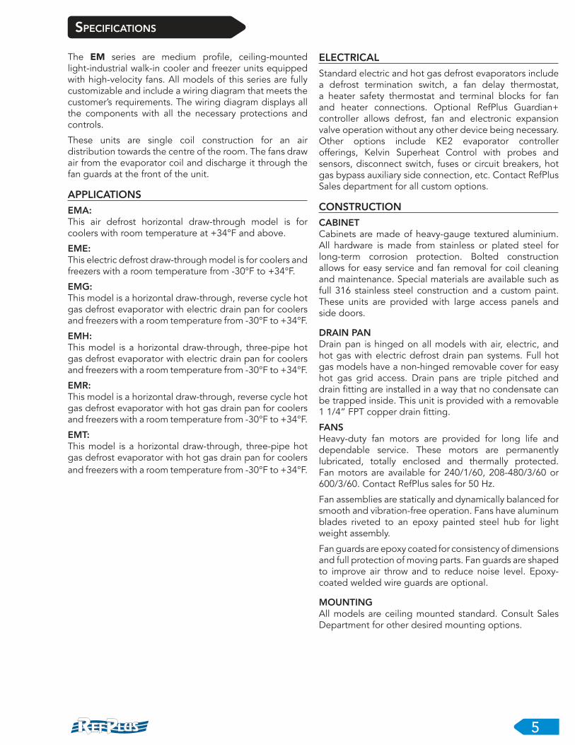
The EM series are medium profile, ceiling-mounted light-industrial walk-in cooler and freezer units equipped with high-velocity fans. All models of this series are fully customizable and include a wiring diagram that meets the customer’s requirements. The wiring diagram displays all the components with all the necessary protections and controls.
These units are single coil construction for an air distribution towards the centre of the room. The fans draw air from the evaporator coil and discharge it through the fan guards at the front of the unit.
APPLICATIONS
EMA:This air defrost horizontal draw-through model is for coolers with room temperature at +34°F and above.
EME:This electric defrost draw-through model is for coolers and freezers with a room temperature from -30°F to +34°F.
EMG:This model is a horizontal draw-through, reverse cycle hot gas defrost evaporator with electric drain pan for coolers and freezers with a room temperature from -30°F to +34°F.
EMH:This model is a horizontal draw-through, three-pipe hot gas defrost evaporator with electric drain pan for coolers and freezers with a room temperature from -30°F to +34°F.
EMR:This model is a horizontal draw-through, reverse cycle hot gas defrost evaporator with hot gas drain pan for coolers and freezers with a room temperature from -30°F to +34°F.
EMT:This model is a horizontal draw-through, three-pipe hot gas defrost evaporator with hot gas drain pan for coolers and freezers with a room temperature from -30°F to +34°F.
ELECTRICAL
Standard electric and hot gas defrost evaporators include a defrost termination switch, a fan delay thermostat, a heater safety thermostat and terminal blocks for fan and heater connections. Optional RefPlus Guardian+ controller allows defrost, fan and electronic expansion valve operation without any other device being necessary. Other options include KE2 evaporator controller offerings, Kelvin Superheat Control with probes and sensors, disconnect switch, fuses or circuit breakers, hot gas bypass auxiliary side connection, etc. Contact RefPlus Sales department for all custom options.
CONSTRUCTION
CABINETCabinets are made of heavy-gauge textured aluminium. All hardware is made from stainless or plated steel for long-term corrosion protection. Bolted construction allows for easy service and fan removal for coil cleaning and maintenance. Special materials are available such as full 316 stainless steel construction and a custom paint. These units are provided with large access panels and side doors.
DRAIN PANDrain pan is hinged on all models with air, electric, and hot gas with electric defrost drain pan systems. Full hot gas models have a non-hinged removable cover for easy hot gas grid access. Drain pans are triple pitched and drain fitting are installed in a way that no condensate can be trapped inside. This unit is provided with a removable 1 1/4” FPT copper drain fitting.
FANSHeavy-duty fan motors are provided for long life and dependable service. These motors are permanently lubricated, totally enclosed and thermally protected. Fan motors are available for 240/1/60, 208-480/3/60 or 600/3/60. Contact RefPlus sales for 50 Hz.
Fan assemblies are statically and dynamically balanced for smooth and vibration-free operation. Fans have aluminum blades riveted to an epoxy painted steel hub for light weight assembly.
Fan guards are epoxy coated for consistency of dimensions and full protection of moving parts. Fan guards are shaped to improve air throw and to reduce noise level. Epoxy-coated welded wire guards are optional.
MOUNTINGAll models are ceiling mounted standard. Consult Sales Department for other desired mounting options.

DRAFT 7
6R
sTandard & opTional feaTures
Standard Features
• AWEF models (see page 12 for list of registered models)
• EC motors for AWEF models - two-speed motors for air defrost - high speed motors for electric & gas deforst
• AC motors for non-AWEF models
• Air throw up to 60 feet
• Cabinet: Stucco aluminum
• Inserted Incoloy electric defrost heaters (EME model only)
• Hinged, insulated drain pan on all air and electric defrost models
• Ready for low GWP refrigerant and CO2 applications
• Ceiling mountable
Available Options
• EC motors 0-10VNote: AWEF requires that ECM 0-10V motors be programmed to operate at maximum 50% while compressor
is off (air defrost units only)
• Two-speed EC motors for electric & gas defrost
• 45o fan deck
• Thermostatic or electronic expansion valve
• Guardian+ smart defrost controller with EC fan speed and electronic expansion valve control and one year free Smart Access
• Liquid line solenoid valve
• Shipped loose room thermostat
• Fans and heaters contactors with fuses or breakers
• Disconnect switch (fused or non-fused)
• Stainless steel casing and drain pan
• Custom painted casing and drain pan (epoxy)
• Black expoxy-coated welded wire guard
• Coil Coating (Blygold, Heresite or Electrofin)• Custom coil design (FPI, material, geometry)
• Hydrophobic epoxy aluminum fins• Auxiliary Side Connection for hot gas bypass
• Mounting bracket kit to match mounting holes of preceding generation with the same casing length
• Air throw boosters
speCifiCaTions (ConTinued)
COIL
Coils are manufactured with seamless deoxidized rifled copper tubes and aluminum corrugated fins. Tubes are mechanically expanded into self-spaced fins plates with full collar for a permanent bond and optimum heat transfer. Connections and bends are brazed with high-temperature brazing alloy. Coils are factory leak tested at 400 psig and purged with a -40°F dew point dry air. Optional nitrogen charge is available.
Coils are circuited for all synthetic refrigerants throughout the evaporator operating range and are also available for CO2 up to 650 PSI (ETL) and 700 PSI (CRN). Recirculated evaporators (SS headers, air or hot gas defrost only) can be rated up to 1741 PSI. Fin spacing is customizable to fit different applications from 8 FPI to 4 FPI. Optional tubing material can be smooth copper, heavy gauge copper for high pressure CO2, cupro-nickel or 316 stainless steel.
Optional fin material can be hydrophobic epoxy aluminum, copper or 316 stainless steel. Optional coatings such as Blygold, Heresite or Electrofin are available for complete coil coverage.
DEFROST SYSTEMS
Electric defrost is done by the means of an internal heating element array, defrosting the coil from the inside out, allowing minimal heat loss in the room. With the help of an optional RefPlus Guardian+ controller, pulsating current and temperature monitoring will allow for majority of frost being sublimated instead of thawed into running water, allowing for better energy efficiency and minimizing the risk of water overflowing.
Hot gas three-pipe defrost includes auxiliary side connection, running from downstream of the expansion valve, through the coil and in the drain pan before going to the suction line.
Reverse cycle defrost allows for two piping connexions only, reducing installation costs on the evaporator. Included is a liquid line bypass with check valve allowing for single liquid line input while allowing hot gas flow to bypass the expansion valve.
Note: Specifications subject to change without notice.

GUARDIAN+
SMART EVAPORATOR
CONTROL SYSTEM
(OPTIONAL)
EEV
ELECTRONIC
EXPANSION VALVE
(OPTIONAL)
DRAIN PAN
INSULATED,
HEATED
AND HINGED
AIR THROW BOOSTER
(OPTIONAL)
45o FAN DECK
(OPTIONAL)
ELECTRICAL PANEL
EASY MAINTENANCE
AND FULLY CONFIGURABLE
INCORPORATED
INSERT HEATERS
(ELECTRIC DEFROST ONLY)
FANS
HEAVY-DUTY
FAN MOTORS
PERMANENT
LUBRICATION
THERMAL
PROTECTION
ALUMINIUM
BLADES
CASING
STUCCO
ALUMINIUM
OPTIONS: EPOXY
PAINT COATED OR
FULL 316 STAINLESS
STEEL
FINS
ALUMINIUM (STANDARD)
COPPER OR 316 STAINLESS STEEL
(OPTIONAL)
BLYGOLD COATING
(OPTIONAL)
BLUE EPOXY COATING
(OPTIONAL)
HERESITE COATING
(OPTIONAL)
RIFLED COPPER TUBING
STAINLESS STEEL TUBING
(OPTIONAL)
ELECTROFIN COATING
(OPTIONAL)
DRAFT 7
7R
sTandard & opTional feaTures

DRAFT 7
8R
CapaCiTy Table Industrial Walk-in Evaporator With High-Velocity Motors
EMA - AIR DEFROST FOR COOLERS ABOVE +34OF
CAPACITIES
ELECTRICAL
MODEL CFM
CAPACITY (MBH) FOR R-448A
(>85% RH)CONNECTION (INCHES) R-448A OPERATING
CHARGE (LB.)
STANDARD UNIT
SHIPPING WEIGHT
(LB.)8°FTD 10°FTD 12°FTD 15°FTD LIQUID SUCTION
EMA-02150 4,200 17.96 22.45 26.94 33.68 1/2 1 1/8 3.97 210
EMA-02550 3,950 21.30 26.62 31.94 39.93 1/2 1 1/8 5.31 225
EMA-03000 3,500 25.06 31.32 37.58 46.98 7/8 1 1/8 7.96 245
EMA-04300 8,400 35.91 44.89 53.87 67.34 7/8 1 3/8 7.53 375
EMA-05100 7,900 42.59 53.24 63.89 79.86 7/8 1 3/8 10.03 400
EMA-06000 7,000 50.11 62.64 75.17 93.96 7/8 1 3/8 15.05 440
EMA-07650 11,850 63.90 79.87 95.84 119.81 7/8 1 5/8 14.76 595
EMA-09000 10,500 75.17 93.96 112.75 140.94 1 3/8 1 5/8 22.11 640
EMA-10200 16,000 85.19 106.49 127.79 159.74 1 3/8 2 1/8 20.65 785
EMA-12000 14,200 100.22 125.28 150.34 187.92 1 3/8 2 1/8 30.98 830
MODEL MOTOR QTY
240/1/60 208-240/3/60 600/3/60 480/3/60
FAN MOTOR FAN MOTOR FAN MOTOR FAN MOTOR
FLA MCA FUSE FLA MCA FUSE FLA MCA FUSE FLA MCA FUSE
EMA-02150 1 5.30 6.63 15 5.30 6.63 15 0.80 1.00 15 0.95 1.19 15
EMA-02550 1 5.30 6.63 15 5.30 6.63 15 0.80 1.00 15 0.95 1.19 15
EMA-03000 1 5.30 6.63 15 5.30 6.63 15 0.80 1.00 15 0.95 1.19 15
EMA-04300 2 10.60 11.93 15 9.18 11.47 20 1.60 1.80 15 1.90 2.14 15
EMA-05100 2 10.60 11.93 15 9.18 11.47 20 1.60 1.80 15 1.90 2.14 15
EMA-06000 2 10.60 11.93 15 9.18 11.47 20 1.60 1.80 15 1.90 2.14 15
EMA-07650 3 15.90 17.23 20 9.18 11.47 20 2.40 2.60 15 2.85 3.09 15
EMA-09000 3 15.90 17.23 20 9.18 11.47 20 2.40 2.60 15 2.85 3.09 15
EMA-10200 4 21.20 22.53 30 18.36 20.65 25 3.20 3.40 15 3.80 4.04 15
EMA-12000 4 21.20 22.53 30 18.36 20.65 25 3.20 3.40 15 3.80 4.04 15
NOTES:
• Capacities are for R-448A. For other refrigerants, please refer to the refrigerant factor table (Page 11).
• Standard units are 8 FPI. For 6 FPI, multiply capacity by 0.9. For 4 FPI, multiply capacity by 0.75.
• Capacities are based on 85% R.H. and 100°F liquid temperature.

DRAFT 7
9R
EME - ELECTRIC DEFROST FOR COOLERS & FREEZERS FROM -30OF TO +34OF
CAPACITIES
ELECTRICAL
MODEL CFM
CAPACITY (MBH) FOR R-448A @ 10°FTD
(>85% RH)CONNECTION (INCHES) R-448A
OPERATING CHARGE
(LB.)
STANDARD UNIT
SHIPPING WEIGHT
(LB.)-40°F -20°F 0°F +20°F LIQUID SUCTION
EME-02000 4,300 16.08 17.75 19.31 20.88 1/2 1 1/8 6.09 255
EME-02400 4,100 19.29 21.30 23.18 25.06 1/2 1 1/8 8.5 265
EME-02900 3,700 23.31 25.73 28.01 30.28 7/8 1 1/8 12.57 295
EME-04000 8,600 32.16 35.50 38.63 41.76 7/8 1 3/8 11.52 455
EME-04800 8,200 38.59 42.60 46.35 50.11 7/8 1 3/8 16.05 480
EME-05800 7,400 46.63 51.47 56.01 60.55 7/8 1 3/8 23.72 540
EME-07200 12,300 57.88 63.89 69.53 75.17 7/8 1 5/8 23.6 720
EME-08700 11,100 69.94 77.20 84.02 90.83 7/8 1 5/8 34.88 772
EME-09600 17,400 77.17 85.19 92.71 100.22 1 3/8 2 1/8 32.22 930
EME-11600 16,600 93.25 102.94 112.02 121.10 1 3/8 2 1/8 48.83 989
MODELMOTOR
QTY
240/1/60 208-240/3/60
FAN MOTOR HEATER FAN MOTOR HEATER
FLA MCA FUSE KW FLA MCA FUSE FLA MCA FUSE KW FLA MCA FUSE
EME-02000 1 5.30 6.63 15 3.84 16.00 20.00 20 5.30 6.63 15 5.11 12.29 15.36 20
EME-02400 1 5.30 6.63 15 3.84 16.00 20.00 20 5.30 6.63 15 5.11 12.29 15.36 20
EME-02900 1 5.30 6.63 15 5.76 24.00 30.00 30 5.30 6.63 15 7.67 18.45 23.06 25
EME-04000 2 10.60 11.93 15 7.68 32.00 40.00 40 9.18 11.47 20 10.22 24.59 30.74 35
EME-04800 2 10.60 11.93 15 7.68 32.00 40.00 40 9.18 11.47 20 10.22 24.59 30.74 35
EME-05800 2 10.60 11.93 15 11.52 48.00 60.00 60 9.18 11.47 20 15.34 36.90 46.13 50
EME-07200 3 15.90 17.23 20 11.52 48.00 60.00 60 9.18 11.47 20 15.34 36.90 46.13 50
EME-08700 3 15.90 17.23 20 17.28 72.00 90.00 2 X 45 9.18 11.47 20 23.01 55.36 69.20 2 X 35
EME-09600 4 21.20 22.53 30 17.28 72.00 90.00 2 X 45 18.36 20.65 25 23.01 55.36 69.20 2 X 35
EME-11600 4 21.20 22.53 30 23.04 96.00 120.00 2 X 60 18.36 20.65 25 30.67 73.78 92.23 2 X 50
MODELMOTOR
QTY
600/3/60 480/3/60
FAN MOTOR HEATER FAN MOTOR HEATER
FLA MCA FUSE KW FLA MCA FUSE FLA MCA MOP KW FLA MCA FUSE
EME-02000 1 0.80 1.00 15 3.84 3.70 4.63 15 0.95 1.19 15 3.27 3.93 4.91 15
EME-02400 1 0.80 1.00 15 3.84 3.70 4.63 15 0.95 1.19 15 3.27 3.93 4.91 15
EME-02900 1 0.80 1.00 15 5.76 5.54 6.93 15 0.95 1.19 15 4.91 5.91 7.39 15
EME-04000 2 1.60 1.80 15 7.68 7.39 9.24 15 1.90 2.14 15 6.55 7.88 9.85 15
EME-04800 2 1.60 1.80 15 7.68 7.39 9.24 15 1.90 2.14 15 6.55 7.88 9.85 15
EME-05800 2 1.60 1.80 15 11.52 11.09 13.86 15 1.90 2.14 15 9.82 11.81 14.76 15
EME-07200 3 2.40 2.60 15 11.52 11.09 13.86 15 2.85 3.09 15 9.82 11.81 14.76 15
EME-08700 3 2.40 2.60 15 17.28 16.63 20.79 25 2.85 3.09 15 14.73 17.72 22.15 25
EME-09600 4 3.20 3.40 15 17.28 16.63 20.79 25 3.80 4.04 15 14.73 17.72 22.15 25
EME-11600 4 3.20 3.40 15 23.04 22.17 27.71 30 3.80 4.04 15 19.64 23.62 29.53 30
NOTES:
• Capacities are for R-448A. For other refrigerants, please refer to the refrigerant factor table (Page 11).
• Standard units are 6 FPI. For 4 FPI, multiply capacity by 0.8.
• Capacities are based on 85% R.H. and 100°F liquid temperature.
CapaCiTy Table Industrial Walk-in Evaporator With High-Velocity Motors
DRAFT 7
10R
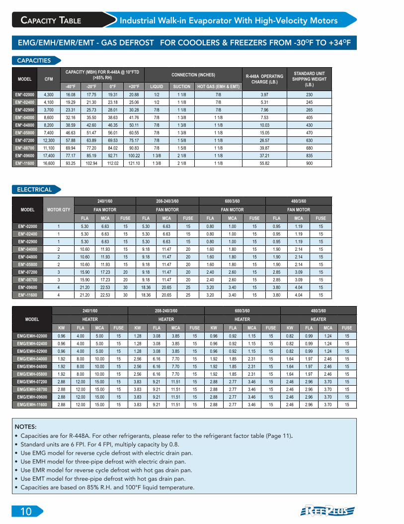
CapaCiTy Table Industrial Walk-in Evaporator With High-Velocity Motors
EMG/EMH/EMR/EMT - GAS DEFROST FOR COOOLERS & FREEZERS FROM -30OF TO +34OF
CAPACITIES
ELECTRICAL
MODEL CFM
CAPACITY (MBH) FOR R-448A @ 10°FTD
(>85% RH)CONNECTION (INCHES) R-448A OPERATING
CHARGE (LB.)
STANDARD UNIT
SHIPPING WEIGHT
(LB.)-40°F -20°F 0°F +20°F LIQUID SUCTION HOT GAS (EMH & EMT)
EM*-02000 4,300 16.08 17.75 19.31 20.88 1/2 1 1/8 7/8 3.97 230
EM*-02400 4,100 19.29 21.30 23.18 25.06 1/2 1 1/8 7/8 5.31 245
EM*-02900 3,700 23.31 25.73 28.01 30.28 7/8 1 1/8 7/8 7.96 265
EM*-04000 8,600 32.16 35.50 38.63 41.76 7/8 1 3/8 1 1/8 7.53 405
EM*-04800 8,200 38.59 42.60 46.35 50.11 7/8 1 3/8 1 1/8 10.03 430
EM*-05800 7,400 46.63 51.47 56.01 60.55 7/8 1 3/8 1 1/8 15.05 470
EM*-07200 12,300 57.88 63.89 69.53 75.17 7/8 1 5/8 1 1/8 26.57 630
EM*-08700 11,100 69.94 77.20 84.02 90.83 7/8 1 5/8 1 1/8 39.87 680
EM*-09600 17,400 77.17 85.19 92.71 100.22 1 3/8 2 1/8 1 1/8 37.21 835
EM*-11600 16,600 93.25 102.94 112.02 121.10 1 3/8 2 1/8 1 1/8 55.82 900
MODEL MOTOR QTY
240/1/60 208-240/3/60 600/3/60 480/3/60
FAN MOTOR FAN MOTOR FAN MOTOR FAN MOTOR
FLA MCA FUSE FLA MCA FUSE FLA MCA FUSE FLA MCA FUSE
EM*-02000 1 5.30 6.63 15 5.30 6.63 15 0.80 1.00 15 0.95 1.19 15
EM*-02400 1 5.30 6.63 15 5.30 6.63 15 0.80 1.00 15 0.95 1.19 15
EM*-02900 1 5.30 6.63 15 5.30 6.63 15 0.80 1.00 15 0.95 1.19 15
EM*-04000 2 10.60 11.93 15 9.18 11.47 20 1.60 1.80 15 1.90 2.14 15
EM*-04800 2 10.60 11.93 15 9.18 11.47 20 1.60 1.80 15 1.90 2.14 15
EM*-05800 2 10.60 11.93 15 9.18 11.47 20 1.60 1.80 15 1.90 2.14 15
EM*-07200 3 15.90 17.23 20 9.18 11.47 20 2.40 2.60 15 2.85 3.09 15
EM*-08700 3 15.90 17.23 20 9.18 11.47 20 2.40 2.60 15 2.85 3.09 15
EM*-09600 4 21.20 22.53 30 18.36 20.65 25 3.20 3.40 15 3.80 4.04 15
EM*-11600 4 21.20 22.53 30 18.36 20.65 25 3.20 3.40 15 3.80 4.04 15
MODEL
240/1/60 208-240/3/60 600/3/60 480/3/60
HEATER HEATER HEATER HEATER
KW FLA MCA FUSE KW FLA MCA FUSE KW FLA MCA FUSE KW FLA MCA FUSE
EMG/EMH-02000 0.96 4.00 5.00 15 1.28 3.08 3.85 15 0.96 0.92 1.15 15 0.82 0.99 1.24 15
EMG/EMH-02400 0.96 4.00 5.00 15 1.28 3.08 3.85 15 0.96 0.92 1.15 15 0.82 0.99 1.24 15
EMG/EMH-02900 0.96 4.00 5.00 15 1.28 3.08 3.85 15 0.96 0.92 1.15 15 0.82 0.99 1.24 15
EMG/EMH-04000 1.92 8.00 10.00 15 2.56 6.16 7.70 15 1.92 1.85 2.31 15 1.64 1.97 2.46 15
EMG/EMH-04800 1.92 8.00 10.00 15 2.56 6.16 7.70 15 1.92 1.85 2.31 15 1.64 1.97 2.46 15
EMG/EMH-05800 1.92 8.00 10.00 15 2.56 6.16 7.70 15 1.92 1.85 2.31 15 1.64 1.97 2.46 15
EMG/EMH-07200 2.88 12.00 15.00 15 3.83 9.21 11.51 15 2.88 2.77 3.46 15 2.46 2.96 3.70 15
EMG/EMH-08700 2.88 12.00 15.00 15 3.83 9.21 11.51 15 2.88 2.77 3.46 15 2.46 2.96 3.70 15
EMG/EMH-09600 2.88 12.00 15.00 15 3.83 9.21 11.51 15 2.88 2.77 3.46 15 2.46 2.96 3.70 15
EMG/EMH-11600 2.88 12.00 15.00 15 3.83 9.21 11.51 15 2.88 2.77 3.46 15 2.46 2.96 3.70 15
NOTES:
• Capacities are for R-448A. For other refrigerants, please refer to the refrigerant factor table (Page 11).
• Standard units are 6 FPI. For 4 FPI, multiply capacity by 0.8.
• Use EMG model for reverse cycle defrost with electric drain pan.
• Use EMH model for three-pipe defrost with electric drain pan.
• Use EMR model for reverse cycle defrost with hot gas drain pan.
• Use EMT model for three-pipe defrost with hot gas drain pan.
• Capacities are based on 85% R.H. and 100°F liquid temperature.

DRAFT 7
11R
How to find capacity for an EME-07200 at -20°F SST, 10°FTD, R-407A with 4 FPI :EME-07200 @ -20°F SST, 10°FTD, R-448A with 6 FPI = 63.89 MBH
63.89 MBH x 0.988 (refrigerant factor) x 0.8 (FPI factor) = 50.50 MBH
CAPACITY CONVERSION FACTOR
FOR OTHER REFRIGERANTS
OPERATING CHARGE CONVERSION
FACTOR FOR OTHER REFRIGERANTS
CAPACITY CONVERSION FACTOR
FOR OTHER FPI
FaCTor Tables
REFRIGERANT FACTOR
R-404A 0.958
R-410A 1.053
R-22 0.976
R-134A 0.869
R-407F 1.008
R-407A 0.988
R-407C 0.988
R-449A 0.997
R-450A 0.810
R-513A 0.914
REFRIGERANT FACTOR
R-404A 0.945
R-410A 0.960
R-22 1.029
R-134A 1.026
R-407F 1.000
R-407A 1.000
R-407C 1.000
R-449A 1.000
R-450A 1.026
R-513A 1.026
FPI FACTOR
6 1.0
5 0.9
4 0.8
FACTOR TABLES BASED ON R-448A DATA
CALCULATION EXAMPLE
Notes: Capacity might slightly differ from Nomis (negligible difference).
Note: For R744 (CO2) application, please contact RefPlus Sales.
Note: For models with standard FPI other than 6, please refer to Nomis or contact RefPlus Sales.
DRAFT 7
12R
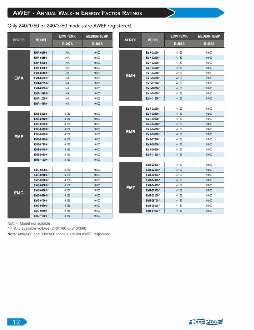
AWEF - Annual Walk-in Energy FaCTor RaTings
SERIES MODELLOW TEMP. MEDIUM TEMP.
R-407A R-407A
EMH
EMH-02000-* 4.150 9.000
EMH-02400-* 4.150 9.000
EMH-02900-* 4.150 9.000
EMH-04000-* 4.150 9.000
EMH-04800-* 4.150 9.000
EMH-05800-* 4.150 9.000
EMH-07200-* 4.150 9.000
EMH-08700-* 4.150 9.000
EMH-09600-* 4.150 9.000
EMH-11600-* 4.150 9.000
EMR
EMR-02000-* 4.150 9.000
EMR-02400-* 4.150 9.000
EMR-02900-* 4.150 9.000
EMR-04000-* 4.150 9.000
EMR-04800-* 4.150 9.000
EMR-05800-* 4.150 9.000
EMR-07200-* 4.150 9.000
EMR-08700-* 4.150 9.000
EMR-09600-* 4.150 9.000
EMR-11600-* 4.150 9.000
EMT
EMT-02000-* 4.150 9.000
EMT-02400-* 4.150 9.000
EMT-02900-* 4.150 9.000
EMT-04000-* 4.150 9.000
EMT-04800-* 4.150 9.000
EMT-05800-* 4.150 9.000
EMT-07200-* 4.150 9.000
EMT-08700-* 4.150 9.000
EMT-09600-* 4.150 9.000
EMT-11600-* 4.150 9.000
SERIES MODELLOW TEMP. MEDIUM TEMP.
R-407A R-407A
EMA
EMA-02150-* N/A 9.000
EMA-02550-* N/A 9.000
EMA-03000-* N/A 9.000
EMA-04300-* N/A 9.000
EMA-05100-* N/A 9.000
EMA-06000-* N/A 9.000
EMA-07650-* N/A 9.000
EMA-09000-* N/A 9.000
EMA-10200-* N/A 9.000
EMA-12000-* N/A 9.000
EMA-16100-* N/A 9.000
EME
EME-02000-* 4.150 9.000
EME-02400-* 4.150 9.000
EME-02900-* 4.150 9.000
EME-04000-* 4.150 9.000
EME-04800-* 4.150 9.000
EME-05800-* 4.150 9.000
EME-07200-* 4.150 9.000
EME-08700-* 4.150 9.000
EME-09600-* 4.150 9.000
EME-11600-* 4.150 9.000
EMG
EMG-02000-* 4.150 9.000
EMG-02400-* 4.150 9.000
EMG-02900-* 4.150 9.000
EMG-04000-* 4.150 9.000
EMG-04800-* 4.150 9.000
EMG-05800-* 4.150 9.000
EMG-07200-* 4.150 9.000
EMG-08700-* 4.150 9.000
EMG-09600-* 4.150 9.000
EMG-11600-* 4.150 9.000
Only 240/1/60 or 240/3/60 models are AWEF registered.
N/A = Model not suitable
* = Any available voltage (240/1/60 or 240/3/60)
Note: 480/3/60 and 600/3/60 models are not AWEF registered.

DRAFT 7
13R
Unit Dimensions
EMA / EME AIR & ELECTRIC DEFROST
MOUNTING HOLES Ø9/16 TYP.
Ø7/8 ELECTRICAL CONNECTIONS
SUCTION LINE
1 1/4 FPT REMOVABLE DRAIN FITTING
2
E
27 1/229
3/4
B
1 1/2
29 1/2 (MAX)
C D
QN
O
7 3/4
H
W (MAX)
# FANUNIT DIMENSIONS (INCHES)
W* H* B* C* D* E* N* O* Q**
1 X 1 54 1/4 29 41 1/2 - - - 28 1/2 5 1/4 23 3/8
1 X 2 94 1/4 29 1/2 40 41 1/2 - - 28 1/2 4 1/2 23 3/8
1 X 3 134 1/4 30 40 41 1/2 40 - 28 1/2 5 23 3/8
1 X 4 134 1/4 40 30 30 31 1/2 30 38 1/2 5 33 3/8
* ±1/2”
** ±1/4”

DRAFT 7
14R
EMG / EMH REVERSE CYCLE & THREE PIPE HOT GAS DEFROST WITH ELECTRIC DRAIN PAN
# FANUNIT DIMENSIONS (INCHES)
W* A* (MAX) H* B* C* D* E* G N* O** Q**
1 X 1 59 54 1/4 29 1/8 41 1/2 - - - 7 7/8 28 1/2 5 1/8 23 3/8
1 X 2 99 94 1/4 29 1/2 40 41 1/2 - - 7 3/4 28 1/2 5 1/8 23 3/8
1 X 3 139 134 1/4 30 40 41 1/2 40 - 7 3/4 28 1/2 5 1/8 23 3/8
1 X 4 139 134 1/4 40 30 30 31 1/2 30 7 3/4 38 1/2 5 1/8 33 3/8
* ±1/2”
** ±1/4”
MOUNTING HOLES Ø9/16 TYP.
Ø7/8 ELECTRICAL CONNECTIONS
SUCTION LINE
1 1/4 FPT REMOVABLE DRAIN FITTING
2
E
27 1/229
3/4
B
1 1/2
29 1/2 (MAX)
C D
QN
5 1/8
7 3/4
H
A (MAX)
W
Unit Dimensions
DRAFT 7
15R
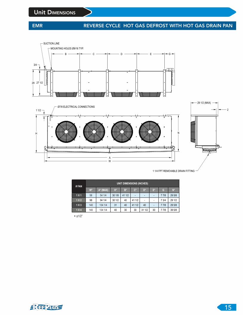
EMR REVERSE CYCLE HOT GAS DEFROST WITH HOT GAS DRAIN PAN
MOUNTING HOLES Ø9/16 TYP.
Ø7/8 ELECTRICAL CONNECTIONS
SUCTION LINE
1 1/4 FPT REMOVABLE DRAIN FITTING
2
E
27 1/229
3/4
B
1 1/2
C D
N
G
H
A
W
29 1/2 (MAX)
# FANUNIT DIMENSIONS (INCHES)
W* A* (MAX) H* B* C* D* E* G N*
1 X 1 58 54 1/4 30 1/8 41 1/2 - - - 7 7/8 29 5/8
1 X 2 98 94 1/4 30 1/2 40 41 1/2 - - 7 3/4 29 1/2
1 X 3 140 134 1/4 31 40 41 1/2 40 - 7 7/8 29 5/8
1 X 4 140 134 1/4 40 30 30 31 1/2 30 7 7/8 39 5/8
* ±1/2”
Unit Dimensions

DRAFT 7
16R
EMT THREE PIPE HOT GAS DEFROST WITH HOT GAS DRAIN PAN
MOUNTING HOLES Ø9/16 TYP.
Ø7/8 ELECTRICAL CONNECTIONS
M1 (HOT GAS CONNECTION)
M2 (SUCTION LINE)
1 1/4 FPT REMOVABLE DRAIN FITTING
2
E
27 1/229
3/4
B
1 1/2
C D
N
G
O
H
A
W
Q
29 1/2 (MAX)
# FANUNIT DIMENSIONS (INCHES)
W* A* (MAX) H* B* C* D* E* G M1 (O.D.) M2 (O.D.) N* O** Q**
1 X 1 58 54 1/4 30 1/8 41 1/2 - - - 7 7/8 1 1/8 1 1/8 29 5/8 5 1/4 23 3/8
1 X 2 98 94 1/4 30 1/2 40 41 1/2 - - 7 3/4 1 1/8 1 3/8 29 5/8 5 1/8 23 3/8
1 X 3 140 134 1/4 31 40 41 1/2 40 - 7 7/8 1 3/8 1 5/8 29 1/2 5 1/8 23 1/4
1 X 4 140 134 1/4 - 30 30 31 1/2 30 7 7/8 1 3/8 2 1/8 39 1/2 5 1/4 33 1/4
* ±1/2”
** ±1/4”
Unit Dimensions

DRAFT 7
17R
Wiring Diagrams
EMA ECM 2-SPEED - 240/1/60
TYPICAL WIRING DIAGRAMS - AIR DEFROST
24
240CT
L1
240/1/60
L2
BR
OW
N
BL
AC
K
OR
AN
GE
YE
LL
OW
GRN/YEL
WHITE
BLUE
1R
1R1
USE COPPER CONDUCTOR ONLY
BR
OW
N
BL
AC
K
OR
AN
GE
YE
LL
OW
GRN/YEL
WHITE
BLUE
240/1/60
"FOR TWO SPEED AND HIGH SPEED IN SYSTEM
OPERATION, THE RELAY MUST BE WIRED"
50VACLASS II
BR
OW
N
BL
AC
K
OR
AN
GE
YE
LL
OW
GRN/YEL
WHITE
BLUEM1 M2 M3
EMA ECM 2-SPEED - 208-230/3/60
24
208CT
L1
208-230/3/60
L3
BR
OW
N
BL
AC
K
OR
AN
GE
YE
LLO
W
GRN/YEL
WHITE
BLUE
1R
1R1
USE COPPER CONDUCTOR ONLY
BR
OW
N
BL
AC
K
OR
AN
GE
YE
LLO
W
GRN/YEL
WHITE
BLUE
240/1/60
"FOR TWO SPEED AND HIGH SPEED IN SYSTEM
OPERATION THE RELAY MUST BE WIRED"
L2
50VA
CLASS II
BR
OW
N
BL
AC
K
OR
AN
GE
YE
LLO
WGRN/YEL
WHITE
BLUE
M1 M2 M3

DRAFT 7
18R
Wiring Diagrams
EME ECM HI-SPEED - 240/1/60
TYPICAL WIRING DIAGRAMS - ELECTRIC DEFROST
24
240CT
L1
240/1/60
L2
BR
OW
N
BL
AC
K
OR
AN
GE
YE
LL
OW
GRN/YEL
WHITE
BLUE
USE COPPER CONDUCTOR ONLY
BR
OW
N
BL
AC
K
OR
AN
GE
YE
LL
OW
GRN/YEL
WHITE
BLUE
50VA
CLASS II
BR
OW
N
BL
AC
K
OR
AN
GE
YE
LL
OW
GRN/YEL
WHITE
BLUE
HS
BR
OW
N
BL
AC
K
RED
DTFDDH
M1 M2 M3
3 C X 4
H1
H2
T2T1
EME ECM HI-SPEED - 208-230/3/60
24
208CT
L1
208-230/3/60
L3
BR
OW
N
BL
AC
K
OR
AN
GE
YE
LLO
W
GRN/YEL
WHITE
BLUE
USE COPPER CONDUCTOR ONLY
BR
OW
N
BL
AC
K
OR
AN
GE
YE
LLO
W
GRN/YEL
WHITE
BLUE
L2
50VA
CLASS II
BR
OW
N
BL
AC
K
OR
AN
GE
YE
LLO
W
GRN/YEL
WHITE
BLUE
HS DTFDDH
M1 M2 M3
3 C X 4
T1 T2 T3
H1
H2
H3
DRAFT 7
19R
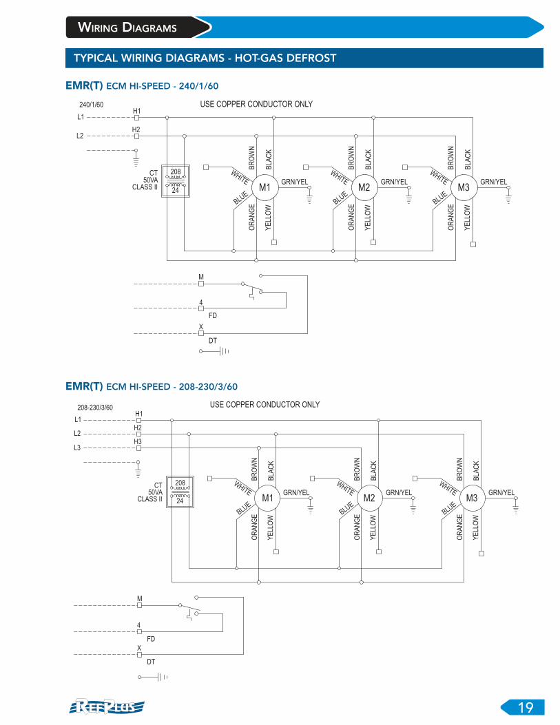
Wiring Diagrams
EMR(T) ECM HI-SPEED - 240/1/60
TYPICAL WIRING DIAGRAMS - HOT-GAS DEFROST
24
208CT
L1
240/1/60
L2
BR
OW
N
BLA
CK
OR
AN
GE
YE
LLO
W
GRN/YEL
WHITE
BLUE
USE COPPER CONDUCTOR ONLY
BR
OW
N
BLA
CK
OR
AN
GE
YE
LLO
W
GRN/YEL
WHITE
BLUE
50VA
CLASS II
BR
OW
N
BLA
CK
OR
AN
GE
YE
LLO
W
GRN/YEL
WHITE
BLUE
M1 M2 M3
H1
H2
M
4
FD
X
DT
EMR(T) ECM HI-SPEED - 208-230/3/60
24
208CT
L1
208-230/3/60
L3
BR
OW
N
BL
AC
K
OR
AN
GE
YE
LLO
W
GRN/YEL
WHITE
BLUE
USE COPPER CONDUCTOR ONLY
BR
OW
N
BL
AC
K
OR
AN
GE
YE
LLO
W
GRN/YEL
WHITE
BLUE
L2
50VA
CLASS II
BR
OW
N
BL
AC
K
OR
AN
GE
YE
LLO
W
GRN/YEL
WHITE
BLUE
M1 M2 M3
H1
H2
H3
M
4
FD
X
DT

DRAFT 7
20R
piping diagrams
TYPICAL PIPING DIAGRAMS
LIQUID LIQUID
LIQUIDLIQUID
DEFROST
NORMAL
DEFROST
NORMAL
HOT GAS
HO
T G
AS
THREE PIPE DEFROSTREVERSE CYCLE DEFROST
ELECTRIC DRAIN
PAN HEATERS
ELECTRIC DRAIN
PAN HEATERS
DEFROST
NORMAL
DE
FR
OS
T
NO
RM
AL
EMR EMT
EMG EMH

Redefining Defrost & Temperature Control
Improved Defrost Efficiency: y Off time defrost on schedule or custom defrost.
y Manual defrost.
y Minimizes frost on evaporator for superior efficiency.
y Eliminates ice formation on floors and ceilings for a safer working place.
y Eliminates ice formation on products.
y Post Defrost Indicator reduces service calls, alerts users when controller is coming out of defrost.
Guardian+ controls both temperature and defrost, providing you with precision set-point and temperature measurement.
It also provides energy savings, 15 to 50% over mechanically controlled systems. Ideal for walk-in coolers, closed door display cases, refrigerated warehouses, meat prep rooms, walk-in freezers and blast freezers.
Guardian+ eliminates unnecessary defrosts typically associated with time-based alternatives thus reducing energy consumption & preserving product integrity.
It also eliminates multiple mechanical controls with precise electronic control.
y Accurate temperature control helps increase product shelf life
y Visual Alarming – High temp/Low temp/Sensor
y Compressor protection – Maximum starts per hour
y Local / Web-based access to monitor and control system operations (Smart Access)
y Key pad lockout prevents unauthorized adjustments
First year FREE Smart Access remote monitoring!
Smart Evaporator Control System
Guardian+
Smart Controller
SmartExpansion Valve
EnergySavings!

Combine your selected unit with the Guardian+
defrost option to obtain an EcoEfficient+ system and optimize your energy efficiency.
R
EM_EN-06/2021-R0
RefPlus Inc. reserves the right to make any changes in the design or
specifications of any product at any time without notice. © Copyright 2021 by RefPlus Inc.
USA & CANADA 1-888-816-2665 / refplus.com2777 Grande-Allée,Saint-Hubert, Québec,Canada,J4T 2R4 T 450 641-2665 F 450 641-4554
CERTIFIED ISO-9001