Medium and high pressure pumps - IMO · Alignment and shaft couplings The pump shall be connected...
12
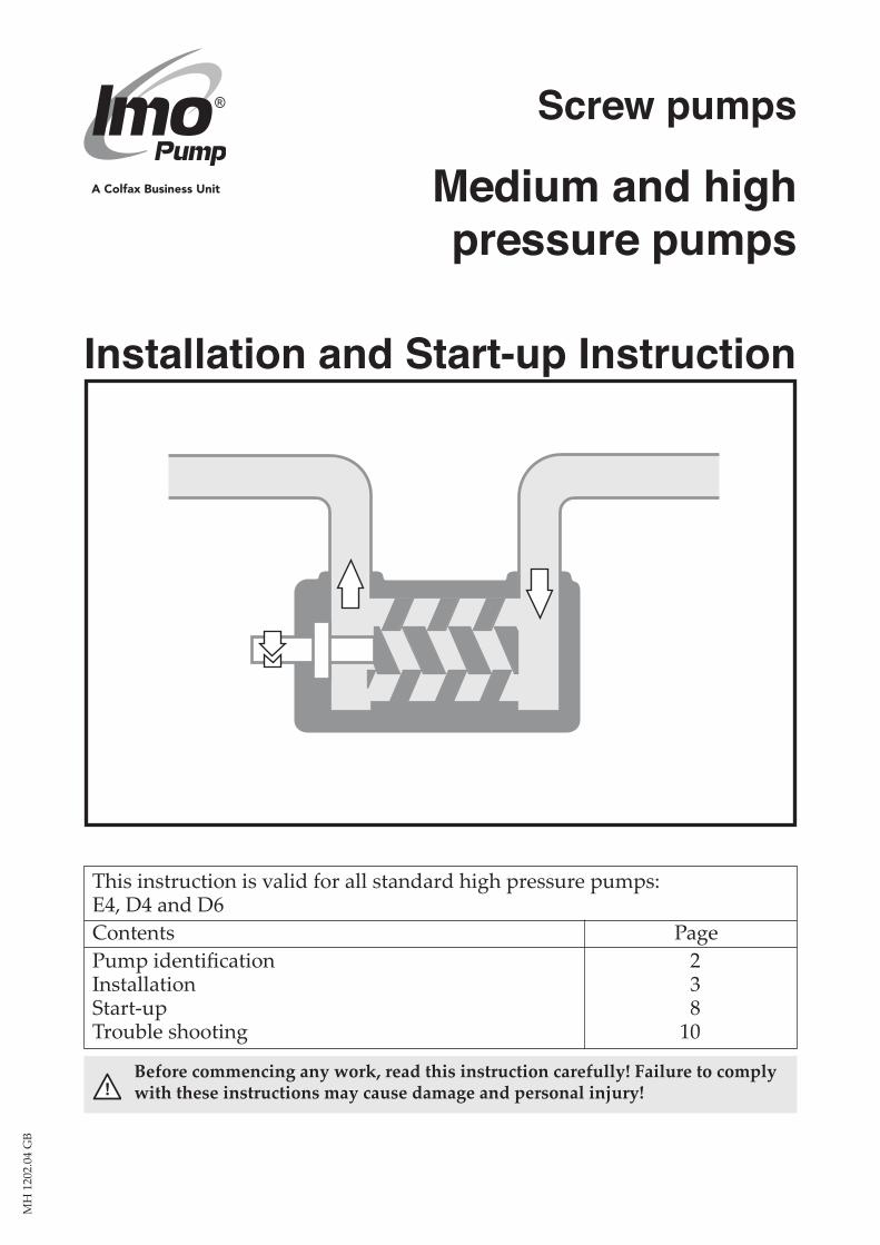
This instruction is valid for all standard high pressure pumps: E4, D4 and D6 Contents Page Pump identification 2 Installation 3 Start-up 8 Trouble shooting 10 ! Before commencing any work, read this instruction carefully! Failure to comply with these instructions may cause damage and personal injury! Medium and high pressure pumps Installation and Start-up Instruction Screw pumps MH 1202.04 GB
Transcript of Medium and high pressure pumps - IMO · Alignment and shaft couplings The pump shall be connected...
This instruction is valid for all standard high pressure pumps: E4, D4 and D6Contents Page Pump identification 2Installation 3Start-up 8Trouble shooting 10
!Before commencing any work, read this instruction carefully! Failure to comply with these instructions may cause damage and personal injury!
Medium and high pressure pumps
Installation and Start-up Instruction
Screw pumps
MH
120
2.04
GB
2 www.imo.se
MH
120
2.04
GB
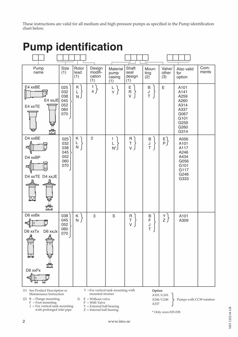
These instructions are valid for all medium and high pressure pumps as specified in the Pump identification chart below.
(1) See Product Description orMaintenance Instruction
(2) B = Flange mountingF = Foot mountingJ = For vertical tank mounting with prolonged inlet pipe
OptionA101/G101A246/G246 Pumps with CCW-rotationA337
T = For vertical tank mounting with mounted strainer
3) E = Without valveP = With ValveY = External ball bearingZ = Internal ball bearing
Com-ments
Pumpname
Materialpumpcasing(1)
Shaftsealdesign(1)
Moun-ting(2)
Valve/other(3)
Designmodifi-cation(1)
Rotorlead(1)
Size(1)
Also validforoption
025032038045052060070
14
KLN
LY
BJT
E A101A141A259A260A314A337G067G101G259G260G314
E4 xxBE
025032038045052060070
KLN
ILN*
BJT
EP
A056A101A117A246A434G056G101G117G246G333
D4 xxBE RTV
ERV
2
038045052060070
KN
S BFJT
YZ
D6 xxBx RTV
3
E4 xxTEE4 xxJE
D4 xxBP
D4 xxTE D4 xxJE
D6 xxTx D6 xxJx
A101A309
D6 xxFx
* Only sizes 025-038
Pump identification
max 90°min 60°
max 90°min 60°
3www.imo.se
MH
120
2.04
GB
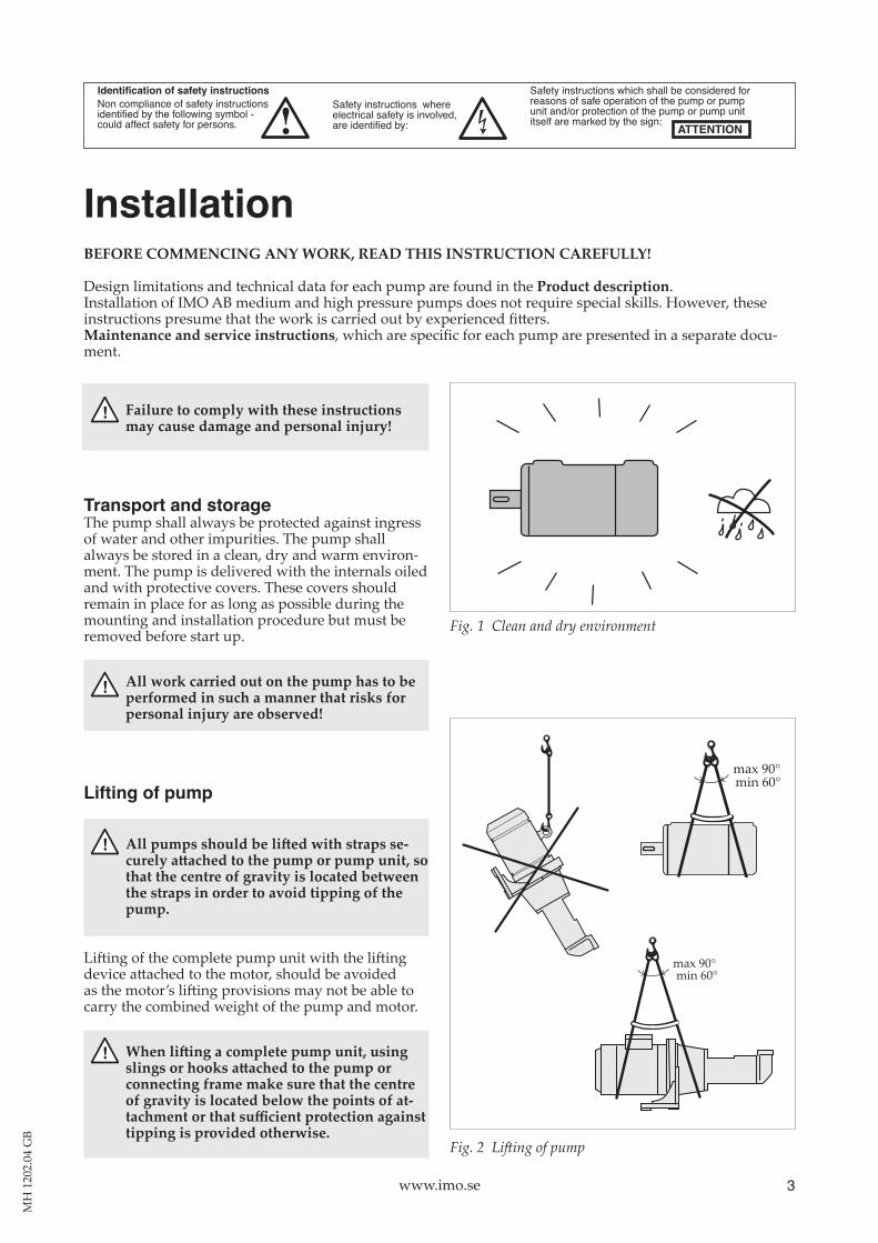
Fig. 2 Lifting of pump
Identification of safety instructionsNon compliance of safety instructionsidentified by the following symbol -could affect safety for persons.
Safety instructions whereelectrical safety is involved,are identified by:
Safety instructions which shall be considered forreasons of safe operation of the pump or pumpunit and/or protection of the pump or pump unititself are marked by the sign:
ATTENTION
InstallationBEFORE COMMENCING ANY WORK, READ THIS INSTRUCTION CAREFULLY!
Design limitations and technical data for each pump are found in the Product description.Installation of IMO AB medium and high pressure pumps does not require special skills. However, these instructions presume that the work is carried out by experienced fitters.Maintenance and service instructions, which are specific for each pump are presented in a separate docu-ment.
Fig. 1 Clean and dry environment
! Failure to comply with these instructions may cause damage and personal injury!
Transport and storageThe pump shall always be protected against ingress of water and other impurities. The pump shall always be stored in a clean, dry and warm environment. The pump is delivered with the internals oiled and with protective covers. These covers should remain in place for as long as possible during the mounting and installation procedure but must be removed before start up.
! All work carried out on the pump has to be performed in such a manner that risks for personal injury are observed!
Lifting of pump
! Allpumpsshouldbeliftedwithstrapssecurelyattachedtothepumporpumpunit,sothat the centre of gravity is located between the straps in order to avoid tipping of the pump.
Lifting of the complete pump unit with the lifting device attached to the motor, should be avoided as the motor’s lifting provisions may not be able to carry the combined weight of the pump and motor.
! Whenliftingacompletepumpunit,usingslingsorhooksattachedtothepumporconnecting frame make sure that the centre of gravity is located below the points of attachmentorthatsufficientprotectionagainsttipping is provided otherwise.
t
D4 ø max 0.3 mmD6 ø max 0.4 mmE4 ø max 0.4 mm
max0.1°
D
4 www.imo.se
MH
120
2.04
GB
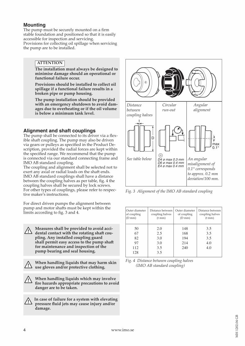
Fig. 3 Alignment of the IMO AB standard coupling
Fig. 4 Distance between coupling halves (IMO AB standard coupling)
Outer diameter of coupling
(mm)
Distance betweencoupling halves
(mm)
Outer diameter of coupling
(mm)
Distance betweencoupling halves
(mm)
50678297
112128
2.02.53.03.03.53.5
148168194214240
3.53.53.54.04.0
MountingThe pump must be securely mounted on a firm stable foundation and positioned so that it is easily accessible for inspection and servicing.Provisions for collecting oil spillage when servicing the pump are to be installed.
ATTENTION The installation must always be designed to
minimise damage should an operational or functional failure occur.
Provisions should be installed to collect oil spillage if a functional failure results in a broken pipe or pump housing.
The pump installation should be provided with an emergency shutdown to avoid damages due to overheating or if the oil volume is below a minimum tank level.
Alignment and shaft couplingsThe pump shall be connected to its driver via a flex-ible shaft coupling. The pump may also be driven via gears or pulleys as specified in the Product De-scription, provided the radial forces are kept within the specified range. We recommend that the pump is connected via our standard connecting frame and IMO AB standard coupling. The coupling and alignment shall be selected not to exert any axial or radial loads on the shaft ends. IMO AB standard couplings shall have a distance between the coupling halves as per table, fig. 4 the coupling halves shall be secured by lock screws.For other types of couplings, please refer to respec-tive maker’s instructions.
For direct driven pumps the alignment between pump and motor shafts must be kept within the limits according to fig. 3 and 4.
! Measures shall be provided to avoid accidentalcontactwiththerotatingshaftcoupling. Any installed coupling guard shallpermiteasyaccesstothepumpshaftfor maintenance and inspection of the pump bearing and seal housing.
! When handling liquids that may harm skin use gloves and/or protective clothing.
! When handling liquids which may involve firehazardsappropriateprecautionstoavoiddanger are to be taken.
! In case of failure for a system with elevating pressurefluidjetsmaycauseinjuryand/ordamage.
See table below An angular misalignment of 0.1° corresponds to approx. 0.2 mm deviation/100 mm.
Angular alignment
Distance between coupling halves
Circularrun-out
Outer diameter Distance between Outer diameter Distance between of coupling coupling halves of coupling coupling halves (D mm) (t mm) (D mm) (t mm)
5www.imo.se
MH
120
2.04
GB
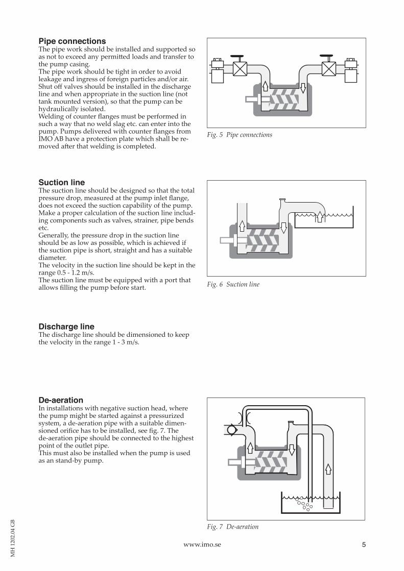
Fig. 7 De-aeration
Pipe connectionsThe pipe work should be installed and supported so as not to exceed any permitted loads and transfer to the pump casing. The pipe work should be tight in order to avoid leakage and ingress of foreign particles and/or air.Shut off valves should be installed in the discharge line and when appropriate in the suction line (not tank mounted version), so that the pump can be hydrauli cally isolated.Welding of counter flanges must be performed in such a way that no weld slag etc. can enter into the pump. Pumps delivered with counter flanges from IMO AB have a protection plate which shall be re-moved after that welding is completed.
Suction lineThe suction line should be designed so that the total pressure drop, measured at the pump inlet flange, does not exceed the suction capability of the pump.Make a proper calculation of the suction line includ-ing components such as valves, strainer, pipe bends etc. Generally, the pressure drop in the suction line should be as low as possible, which is achieved if the suction pipe is short, straight and has a suitable diameter.The velocity in the suction line should be kept in the range 0.5 1.2 m/s.The suction line must be equipped with a port that allows filling the pump before start.
Discharge lineThe discharge line should be dimensioned to keep the velocity in the range 1 3 m/s.
De-aerationIn installations with negative suction head, where the pump might be started against a pressurized system, a deaeration pipe with a suitable dimen-sioned orifice has to be installed, see fig. 7. The de-aeration pipe should be connected to the highest point of the outlet pipe. This must also be installed when the pump is used as an standby pump.
Fig. 5 Pipe connections
Fig. 6 Suction line
6 www.imo.se
MH
120
2.04
GB
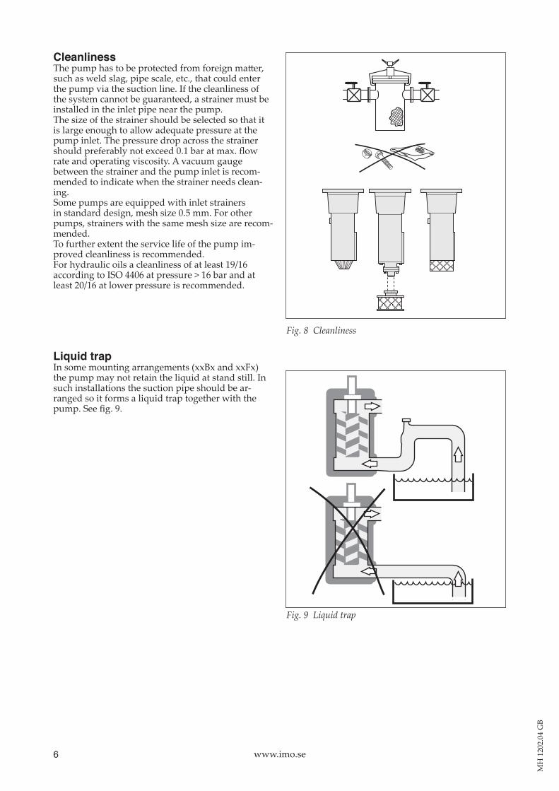
CleanlinessThe pump has to be protected from foreign matter, such as weld slag, pipe scale, etc., that could enter the pump via the suction line. If the cleanliness of the system cannot be guaranteed, a strainer must be installed in the inlet pipe near the pump. The size of the strainer should be selected so that it is large enough to allow adequate pressure at the pump inlet. The pressure drop across the strainer should preferably not exceed 0.1 bar at max. flow rate and operating viscosity. A vacuum gauge between the strainer and the pump inlet is recom-mended to indicate when the strainer needs clean-ing.Some pumps are equipped with inlet strainers in standard design, mesh size 0.5 mm. For other pumps, strainers with the same mesh size are recom-mended.To further extent the service life of the pump im-proved cleanliness is recommended. For hydraulic oils a cleanliness of at least 19/16according to ISO 4406 at pressure > 16 bar and at least 20/16 at lower pressure is recommended.
Liquid trap In some mounting arrangements (xxBx and xxFx) the pump may not retain the liquid at stand still. In such installations the suction pipe should be ar-ranged so it forms a liquid trap together with the pump. See fig. 9.
Fig. 9 Liquid trap
Fig. 8 Cleanliness

bar
7www.imo.se
MH
120
2.04
GB
Fig. 10 External pressure relief valve
Safety valvePumps not equipped with an internal valve require a separate relief valve connected to the delivery pipe to limit fluid pressure. Locate the pressure relief valve as close to the pump outlet port as possible, preferably upstream of a check valve, where so equipped. The return line from the valve should be run back to a suitable position in the tank to limit the temperature rise in the pump when overflow takes place. Set the valve opening pressure as low as correspon-ding to satisfactory system performance. Do not choose an opening pressure in excess of the maxi-mum operating pressure of the pump.
The D4 xxBP pump is supplied from IMO AB with an integrated pressure relief valve designed for external overflow. The return line from the pressure relief valve should be run back to the tank to limit the temperature rise in the pump when overflow takes place.
Pressure testing and flushingThe system must be flushed with the pump replaced by a dummy pipe and pressure tested before con-necting the pump. If corrosive liquid, such as water is used, the system must be thoroughly drained, dried and protected against corrosion before the pump is reinstalled as otherwise the pump might be damaged before start-up due to internal corrosion.
! Oilleakagemaymakethefloorslippery and cause personal injury.
Pressure gauge There should be a tap point for connecting a pres-sure gauge to the delivery pipe to adjust and check the setting of the pressure relief valve. Some pumps are equipped with pressure taps.
Fig. 11 Pressure gauges

8 www.imo.se
MH
120
2.04
GB
Start-upBefore startingAfter installation or whenever it can be assumed that the pump has been emptied, the pump must be thoroughly filled with liquid. See chapter ”Suction Line ”, page 5.
! Make sure the prime mover is disconnected and can not be started accidentally.
While filling the pump rotate the shaft by hand. If the shaft is not accessible, rotation can be performed from the motor fan, to ensure that the rotor bores and the shaft seal com part ment is filled.
! Donotforgettofitthemotorfancoveragainbefore making start of motor possible.
Open the shutoff valves in the inlet and delivery pipes to the full extent. Set pump pressure relief valve at the lowest opening pressure. The pump is now ready for starting.
If the suction pipe cannot be completely filled, it is important to ensure that the trapped air is evacuated without any pressure build up. (See fig. 7 De aeration).
ATTENTION
Starting a dry pump is likely to cause damage to the pump.
Direction of rotationWhen the pump is ready to be started, switch the motor briefly on and off and check that the drive motor rotates in the correct direction as indicated by the rotation arrow.Check the direction of rotation by watching the fan on the electric motor.
Fig. 12 Filling the pump before starting
Fig. 13 Direction of rotation
Bar
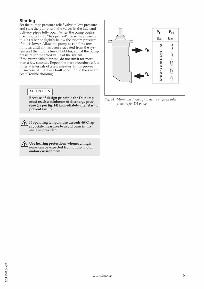
0123456789
10
Bar
45678
142026323844
PL PH
PH
PL
9www.imo.se
MH
120
2.04
GB
StartingSet the pumps pressure relief valve to low pressure and start the pump with the valves in the inlet and delivery pipes fully open. When the pump begins discharging fluid, ”has primed”, raise the pressure to 1.01.5 bar or slightly below the system pressure if this is lower. Allow the pump to run for a few minutes until air has been evacuated from the sys-tem and the fluid is free of bubbles, adjust the pump pressure for the rated value of the system. If the pump fails to prime, do not run it for more than a few seconds. Repeat the start procedure a few times at intervals of a few minutes. If this proves unsuccessful, there is a fault condition in the system. See ”Trouble shooting”.
ATTENTION
Because of design principle the D4 pump must reach a minimum of discharge pressure(asperfig.14)immediatelyafterstarttoprevent failure.
! If operating temperature exceeds 60°C, appropriate measures to avoid burn injury shall be provided.
! Use hearing protections whenever high noise can be expected from pump, motor and/or environment.
Fig. 14 Minimum discharge pressure at given inlet pressure for D4 pump
10 www.imo.se
MH
120
2.04
GB
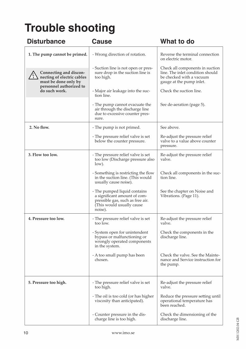
Trouble shooting
Wrong direction of rotation.
- Suction line is not open or pres-sure drop in the suction line is too high.
Major air leakage into the suc-tion line.
- The pump cannot evacuate the air through the discharge line due to excessive counter pres-sure.
The pump is not primed.
- The pressure relief valve is set below the counter pressure.
- The pressure relief valve is set too low (Discharge pressure also low).
Something is restricting the flow in the suction line. (This would usually cause noise).
The pumped liquid contains a significant amount of compressible gas, such as free air. (This would usually cause noise).
- The pressure relief valve is set too low.
System open for unintendent bypass or malfunctioning or wrongly operated components in the system.
- A too small pump has been chosen.
- The pressure relief valve is set too high.
- The oil is too cold (or has higher viscosity than anticipated).
- Counter pressure in the dis-charge line is too high.
1.Thepumpcannotbeprimed.
Connecting and disconnecting of electric cables must be done only by personnelauthorizedtodo such work.
2.Noflow.
3. Flow too low.
4. Pressure too low.
5. Pressure too high.
Reverse the terminal connection on electric motor.
Check all components in suction line. The inlet condition should be checked with a vacuum gauge at the pump inlet.
Check the suction line.
See deaeration (page 5).
See above.
Readjust the pressure relief valve to a value above counter pressure.
Readjust the pressure relief valve.
Check all components in the suc-tion line.
See the chapter on Noise and Vibrations. (Page 11).
Readjust the pressure relief valve.
Check the components in the discharge line.
Check the valve. See the Mainte-nance and Service instruction for the pump.
Readjust the pressure relief valve.
Reduce the pressure setting until operational temperature has been reached.
Check the dimensioning of the discharge line.
What to doDisturbance Cause
11www.imo.se
MH
120
2.04
GB
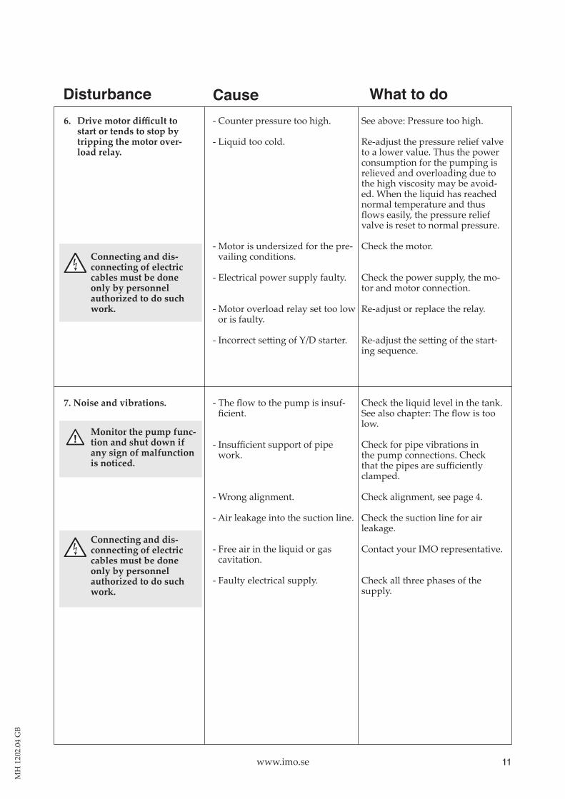
What to doDisturbance Cause6.Drivemotordifficultto
start or tends to stop by tripping the motor overload relay.
Connecting and disconnecting of electric cables must be done only by personnel authorizedtodosuchwork.
7. Noise and vibrations.
! Monitor the pump function and shut down if any sign of malfunction is noticed.
Connecting and disconnecting of electric cables must be done only by personnel authorizedtodosuchwork.
Counter pressure too high.
Liquid too cold.
- Motor is undersized for the pre-vailing conditions.
Electrical power supply faulty.
Motor overload relay set too low or is faulty.
Incorrect setting of Y/D starter.
The flow to the pump is insuf-ficient.
Insufficient support of pipe work.
Wrong alignment.
Air leakage into the suction line.
Free air in the liquid or gas cavitation.
Faulty electrical supply.
See above: Pressure too high.
Readjust the pressure relief valve to a lower value. Thus the power con sumption for the pumping is re lieved and overloading due to the high viscosity may be avoid-ed. When the liquid has reached nor mal temperature and thus flows easily, the pressure relief valve is reset to normal pressure.
Check the motor.
Check the power supply, the mo-tor and motor connection.
Readjust or replace the relay.
Readjust the setting of the start-ing sequence.
Check the liquid level in the tank. See also chapter: The flow is too low.
Check for pipe vibrations in the pump connections. Check that the pipes are sufficiently clamped.
Check alignment, see page 4.
Check the suction line for air leakage.
Contact your IMO representative.
Check all three phases of the supply.