Medical Photonics Lecture 1.2 Optical EngineeringEngineering... · Pupil mismatch between patient...
36
www.iap.uni-jena.de Medical Photonics Lecture 1.2 Optical Engineering Lecture 10: Instruments III 2017-01-05 Michael Kempe Winter term 2016
Transcript of Medical Photonics Lecture 1.2 Optical EngineeringEngineering... · Pupil mismatch between patient...

www.iap.uni-jena.de
Medical Photonics Lecture 1.2Optical Engineering
Lecture 10: Instruments III
2017-01-05
Michael Kempe
Winter term 2016

2
Contents
No Subject Ref Date Detailed Content
1 Introduction Gross 20.10. Materials, dispersion, ray picture, geometrical approach, paraxial approximation
2 Geometrical optics Gross 03.11. Ray tracing, matrix approach, aberrations, imaging, Lagrange invariant
3 Components Kempe 10.11. Lenses, micro-optics, mirrors, prisms, gratings
4 Optical systems Gross 17.11. Field, aperture, pupil, magnification, infinity cases, lens makers formula, etendue, vignetting
5 Aberrations Gross 24.11. Introduction, primary aberrations, miscellaneous
6 Diffraction Gross 01.12. Basic phenomena, wave optics, interference, diffraction calculation, point spread function, transfer function
7 Image quality Kempe 08.12. Spot, ray aberration curves, PSF and MTF, criteria8 Instruments I Kempe 15.12. Human eye, loupe, eyepieces, photographic lenses
9 Instruments II Kempe 22.12. Microscopic systems, micro objectives, illumination, scanning microscopes, contrasts
10 Instruments III Kempe 05.01. Medical optical systems, endoscopes, ophthalmic devices, surgical microscopes, zoom systems
11 Optic design Gross 12.01. Aberration correction, system layouts, optimization, realization aspects
12 Photometry Gross 19.01. Notations, fundamental laws, Lambert source, radiative transfer, photometry of optical systems, color theory
13 Illumination systems Gross 26.01. Light sources, basic systems, quality criteria, nonsequential raytrace
14 Metrology Gross 02.02. Measurement of basic parameters, quality measurements

Key Limitation of Optical Imaging in Medicine
𝐼𝐼𝐼𝐼0
= 𝑒𝑒𝑒𝑒𝑒𝑒 − 𝜇𝜇𝑠𝑠′ + 𝜇𝜇𝑎𝑎 𝑑𝑑
𝜇𝜇𝑠𝑠′: reduced scattering coefficient(typ. 101 − 102 𝑐𝑐𝑐𝑐−1)
𝜇𝜇𝑠𝑠: scattering coefficient(typ. 102 − 103 𝑐𝑐𝑐𝑐−1)
𝜇𝜇𝑎𝑎: absorption coefficient
Penetration / Resolution:
Ballistic light (𝜇𝜇𝑠𝑠) – few mm / several µmDiffuse light (𝜇𝜇𝑠𝑠′) – depth d

Optical Imaging in Medicine
Optical Medical Imaging
Diagnostic Imaging
Ophthalmology
Dermatology
Others
Surgical Imaging
Neuro/Spine
Gynaecology/Urology
ENT
Ophthalmology
Dental
Endoscopy
Gastroenterology
Cardiology
Urology
Pulmonology
Others

Endoscopes: Relay Systems
Endoscopes use various light guiding principles to relay the image overdistance
Rigid endoscopes – slab lens relay Combination of several relay subsystems Large field-angle objective lens
objective 1. relay 2. relay 3. relay
Ref.: M. Rill

Rigid Endoscopes
0.5
486 nm587 nm656 nm
0.4
00 0.4
Wrms [λ]
0.8 1.2 21.6y'
[mm]
0.3
0.2
0.1
diffraction limit
Example: Systems by Storz diameter 3.7 mm

Flexible Endoscopes
Helen D. Ford and Ralph P. Tatam, "Characterization of optical fiber imaging bundles for swept-source optical coherence tomography," Appl. Opt. 50, 627-640 (2011)
Use of fiber bundle array as relay
Each fiber transmits one image point Diameter: typ. 0.5-1.5 mm for 4k to 18k fibers
(data points = pixels) Pixel size: typ. 6-10 µm
Example: System by Storz

8
Optical Ophthalmic Diagnosis
Imaging
Anterior Segment
Slit lamp
OCT
Posterior Segment
Slit lamp
Ophthalmoscope
Fundus Camera
OCT
Measuring
Refractive Power
Objective Refraction:
Autorefractor
Subjective Refraction:Phoropter
Wavefront
Aberrometer
Visual Field
Perimeter
Cornea Topography
Topographer (Placido)
Keratometer
Eye lengths
Biometer (OCT)
Retinal layers
OCT

9
Slit Lamp
Ref.: ZEISS
Köhler Illumination (“slit lamp”)a) from below (Zeiss type)b) from above (Haag Steit type)
Stereo microscope
CMO type Greenough type
http://media.labcompare.com/

10
Stereo Microscopes
Greenough Type• Well-corrected objective
lenses• Inclined image planes
CMO Type (Common Main Objective)• Main objective used off-
axis • Varying aberrations on
both channels (globe effect)

11
Slit Lamp
Projection of a slit onto thecornea with small NA
Scattering in the eye Scanning in the anterior of
the eye to detect inhomo-geneities
With the use of (neg.) contact lens or (pos.) auxilliary lens imaging of thefundus is possible
Ref.: M. Kaschke et al. Ophthalmology
Diffuse illumination Slit illumination
ParfocalSwivel

12
Direct Ophthalmoscope
Inspection of an illumination pathreflected on the retina withoutmicroscope
Selection of different aperturesby a rotatable wheel
Compensation lens forces acoincidence with the observation
Ref.: M. Kaschke et al. Ophthalmology

13
Indirect Ophthalmoscope
Pupil mismatch between patient and observer reduces field of view in direct ophthalmoscope
Indirect phthalmoscope: additional ophthamoscopy lens close to the eye creates an enlarged image of the patients pupil
Ref.: M. Kaschke et al. Ophthalmology

14
Fundus Camera
Observation and photographic inspection of the retina Inspection of the fundus structural analysis to detect morphological deceases Separation of illumination and observation beam path to avoid disturbing reflections Typically ring-shaped illumination
Ref.: M. Kaschke et al. Ophthalmology

15
Fundus Camera Modalities
Ref.: M. Kaschke et al. Ophthalmology

16
Confocal Laser Scanning Ophthalmoscope
Confocal imaging of a fundus spot by scanning (CSLO)
Pinhole mirror separates illumination and detection
Confocal pinhole suppresses straylight
Ref.: M. Kaschke et al. Ophthalmology
17
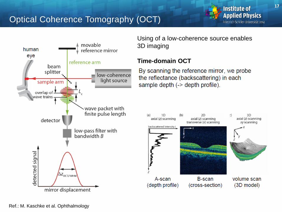
Optical Coherence Tomography (OCT)
Using of a low-coherence source enables 3D imaging
Time-domain OCT
Ref.: M. Kaschke et al. Ophthalmology

18
Optical Coherence Tomography (OCT)
Ref.: M. Kaschke et al. Ophthalmology
Spectral-domain OCT
• Better sensitivity by simultaneous detection of spectral components
• Depth information obtained by Fourier transform
Ref.: ZEISS

19
Optical Coherence Tomography (OCT)
Ref.: Zeiss
OCT-Scan
OCT-Scan
For Glaucoma diagnostics: Either measurement of topology of the blind spotor the thickness of the RNFL
Thickness of RNFL
Measurement against normative database:
Topology of the nerve head
RNFL = Retina Nerve Fiber LayerThe yellow band represents healthy persons
is measured by a circular OCT scan
Depth information enables measurement of layer thickness for diagnosis

20
Refractometer
Autorefraction measurement of the eye power
Test pattern projected onto the retina (mire = target pattern)
Fundus reflected light is observed (Ophthalmoscope)
z-differences corresponds to focal power errors
Ref.: M. Kaschke et al. Ophthalmology

21
Aberrometer
Measurement of the human eye wavefront with a Hartmann-Shack wavefront sensor
Illumination spot on the fundus reflected
Ref.: M. Kaschke et al. Ophthalmology

22
Keratometer
Measuring the refractivepower of the cornea
Main contribution: curvature,only R measured
Principle:Determination of image size y‚
To correct for motion a double image is used as reference
Ref.: M. Kaschke et al. Ophthalmology
1𝑠𝑠′
=1𝑠𝑠
+1𝑓𝑓′
𝑦𝑦′𝑦𝑦
=𝑠𝑠′𝑠𝑠
𝑟𝑟𝑐𝑐 = 2𝑓𝑓′ = 2𝑠𝑠 � 𝑦𝑦′𝑦𝑦
y’∆y

23
Keratometer
Helmholtz-type keratometer
Littmann keratometer
Achieved accuracy: ∆rc = 0.05...0.1 mm
Ref.: M. Kaschke et al. Ophthalmology

24
Cornea Topography by Placido Disk
Projection of a ring mask onto the cornea (Placido mask) Imaging the rings onto a camera Evaluation of the imaged ring widths Reconstruction of the topology of the cornea
Ref.: M. Kaschke et al. Ophthalmology
projected patternimage
reconstructedtopology
real deformedimage

25
Corneal Topographer
Realization of the Placido-projectionand imaging of the reflected light
Ring-by-ring reconstruction of thecornea surface
Ref.: M. Kaschke et al. Ophthalmology
26
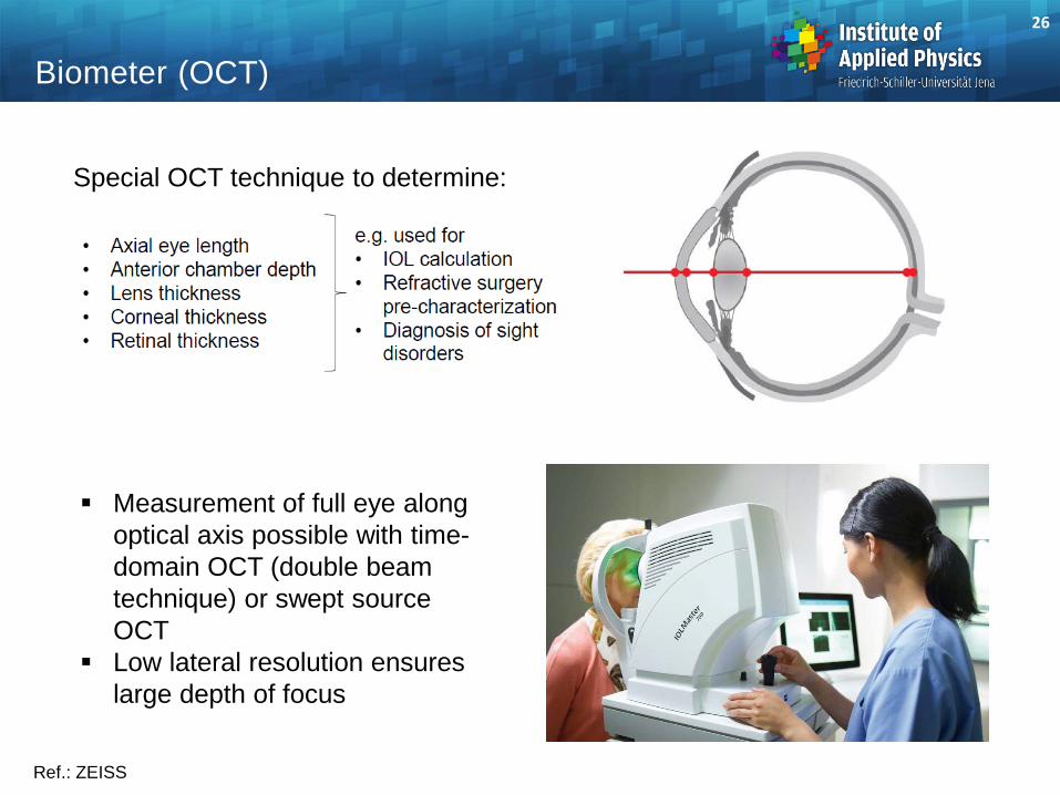
Biometer (OCT)
Ref.: ZEISS
Special OCT technique to determine:
Measurement of full eye along optical axis possible with time-domain OCT (double beam technique) or swept source OCT
Low lateral resolution ensures large depth of focus

Historical Development of Surgical Microscopes
1. Head worn loupe (1876) 4. OPMI (Littmann 1953)2. Corneal loupe (von Zehender/Westien 1887) 5. Contraves Stativ (Yasargil 1972)3. Corneal loupe (Schanz/Czapski 1899)
1.
4.3.
2.
5.

Surgical Microscope
Modern surgical microscopes are stereo systemscombining ocular and digital imaging
Ref.: ZEISS
SurgicalMicroscope
ComputerData TransferPower Supply
Ref.: M. Kaschke et al. Ophthalmology
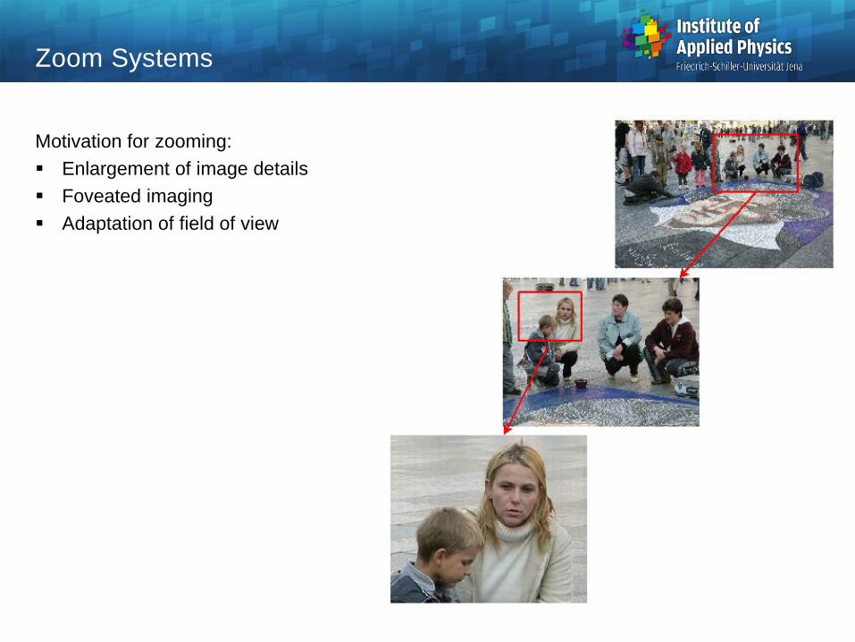
Zoom Systems
Motivation for zooming: Enlargement of image details Foveated imaging Adaptation of field of view

Basic Principle
Two thin lenses in a certain distance t:Focal length
Refractive power
Many types of zoom systemlayouts
tfffff
−+=
21
21
2121 FFtFFF ⋅−+=
c) Infinite-infinite (I-I)
b) Infinite-finite (I-F)
a) Finite-finite (F-F)

Change of Focal Length
Distance t increased First lens fixed
movedlens
changeddistance
t changed focallength f
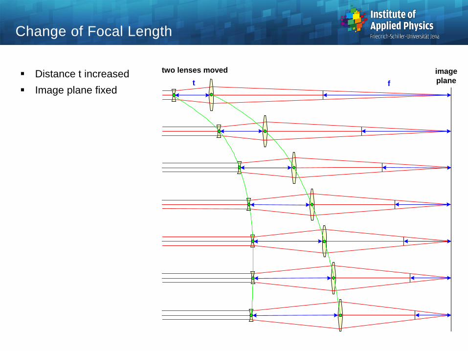
Change of Focal Length
Distance t increased Image plane fixed
two lenses moved t f
imageplane

Mechanical Compensated Zoom Systems
Simple explanation of variator and compensator Movement of variator arbitrary Compensator movement
depends on variator,nonlinear
Perfect invariance ofimage plane possible
objectivelens
variatorlinear
compensatornonlinear
relaylens
P
P
P
imageplane
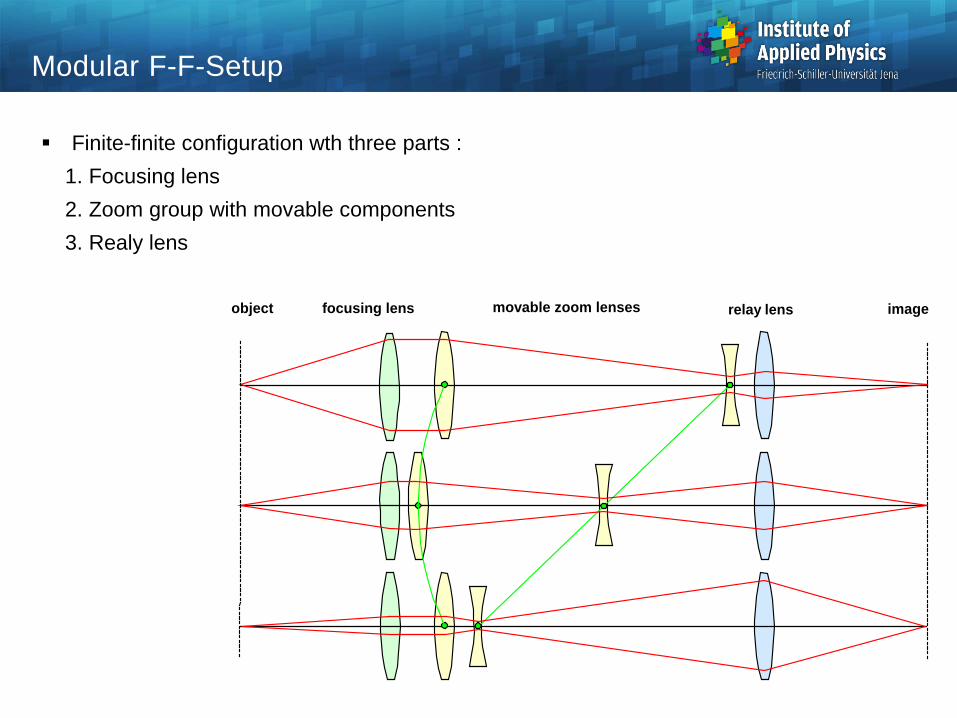
Modular F-F-Setup
Finite-finite configuration wth three parts : 1. Focusing lens2. Zoom group with movable components3. Realy lens
movable zoom lensesfocusing lens relay lensobject image

Symmetrical Three Component I-I Setup
Telescope angle magnification :
Major positions
Symmetrical layout
f1 f1f2
asymmetric 1
Γ > 1
tmax
asymmetric 2
tmin
Γ < 1
symmetric
tm tm
Γ = 1
last
first
hh
ww
=='
Γ
Magnification First distance
Second distance
|Γ| = |Γmax| > 1 tmax 0 |Γ| = 1 tm tm
|Γ| = 1/|Γmax| < 1 0 tmin
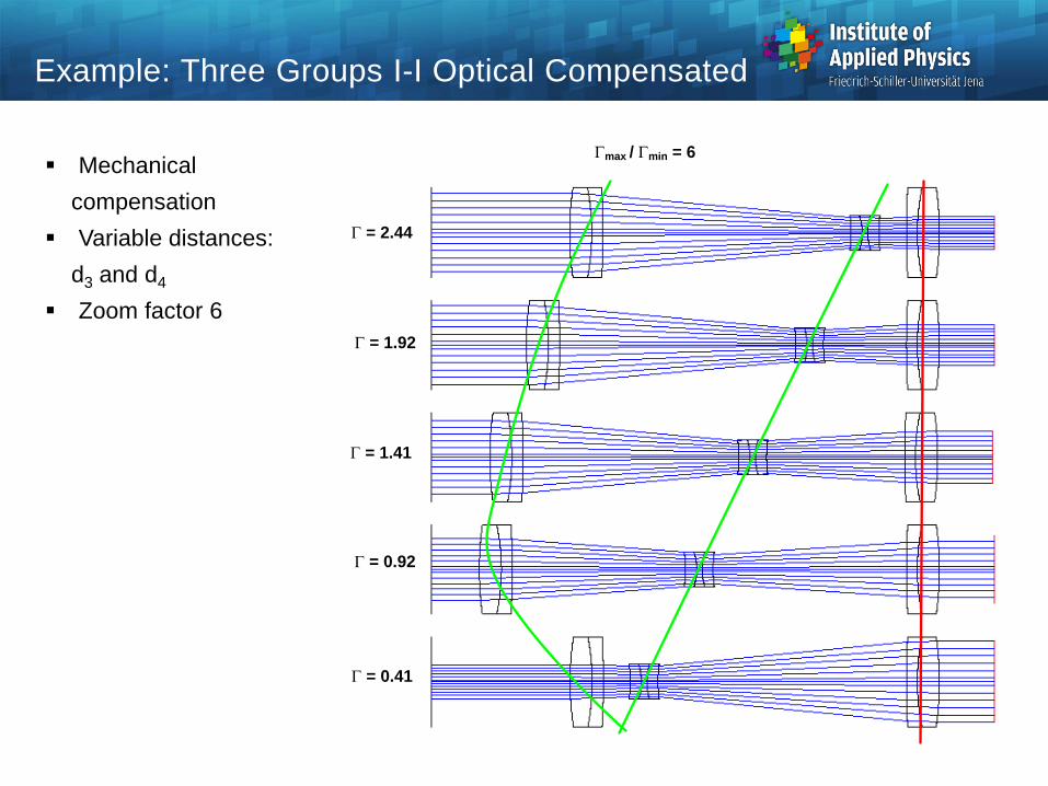
Example: Three Groups I-I Optical Compensated
Γmax / Γmin = 6
Γ = 0.41
Γ = 0.92
Γ = 1.41
Γ = 1.92
Γ = 2.44
Mechanical compensation
Variable distances:d3 and d4
Zoom factor 6