Medical electrical equipment Part 1-2 General requirements...
127
KINGDOM OF SAUDI ARABIA SAUDI STANDARDS, METROLOGY AND QUALITY ORGANIZATION SASO SAUDI STANDARD DRAFT No19981 /2011 MEDICAL ELECTRICAL EQUIPMENT – Part 1-2: General requirements for basic safety and essential performance – Collateral standard: Electromagnetic compatibility – Requirements and tests SAUDI STANDARDS,METROLOGY AND QUALITY ORGANIZATION THIS DOCUMENT IS A DRAFT SAUDI STANDARD CIRCULATED FOR COMMENT. IT IS, THEREFORE SUBJECT TO CHANGE AND MAY NOT BE REFERRED TO AS A SAUDI STANDARD UNTIL APPROVED BY THE BOARD OF DIRECTORS.
Transcript of Medical electrical equipment Part 1-2 General requirements...
KINGDOM OF SAUDI ARABIA SAUDI STANDARDS, METROLOGY AND QUALITY ORGANIZATION
SASO
SAUDI STANDARD
DRAFT No19981 /2011
MEDICAL ELECTRICAL EQUIPMENT –
Part 1-2: General requirements for basic safety and essential performance –
Collateral standard: Electromagnetic compatibility – Requirements and tests
SAUDI STANDARDS,METROLOGY AND QUALITY ORGANIZATION
THIS DOCUMENT IS A DRAFT SAUDI STANDARD CIRCULATED FOR COMMENT. IT IS, THEREFORE SUBJECT TO CHANGE AND MAY NOT BE REFERRED TO AS A SAUDI STANDARD UNTIL APPROVED BY THE BOARD OF DIRECTORS.

SAUDI ARABIAN STANDARD SASO IEC60601-1-2/2011
2
CONTENTS
INTRODUCTION ............................................................................ .اإلشارة المرجعية غير معرفة! خطأ 1 Scope, object and related standards ............................................................................... 6
1.1 * Scope ................................................................................................................. 6 1.2 Object ................................................................................................................... 6 1.3 Related standards ................................................................................................. 6
2 Normative references ..................................................................................................... 6 3 Terms and definitions ..................................................................................................... 8 4 General requirements ................................................................................................... 11
4.1 General requirements for ELECTROMAGNETIC COMPATIBILITY of ME EQUIPMENT and ME SYSTEMS .................................................................................................. 11
4.2 * SINGLE FAULT CONDITION for ME EQUIPMENT .......................................................... 12 5 Identification, marking and documents .......................................................................... 12
5.1 Marking on the outside of ME EQUIPMENT or ME EQUIPMENT parts ........................... 12 5.2 ACCOMPANYING DOCUMENTS .................................................................................. 14
6 ELECTROMAGNETIC COMPATIBILITY ................................................................................... 38 6.1 EMISSIONS ........................................................................................................... 38 6.2 IMMUNITY ............................................................................................................. 41
Annex A (informative) General guidance and rationale ....................................................... 57 Annex B (informative) Guide to marking and labelling requirements for ME EQUIPMENT and ME SYSTEMS .................................................................................................................. 88 Annex C (informative) Example completion of Table 1 through Table 8 ............................... 92 Annex D (informative) Guidance in classification according to CISPR 11 .......................... 105 Annex E (informative) Guidance in the application of IEC 60601-1-2 to particular standards ......................................................................................................................... 108 Annex F (informative) ELECTROMAGNETIC ENVIRONMENTS ................................................... 111 Annex G (informative) Guidance for determining if electrical equipment that is not ME EQUIPMENT and that is used in an ME SYSTEM is exempt from the EMC testing requirements of this collateral standard ............................................................................. 112 Annex H (informative) Mapping between the elements of the second edition of IEC 60601-1-2 as amended and IEC 60601-1-2:2007 ........................................................ 115 Bibliography ..................................................................................................................... 124 Index of defined terms used in this collateral standard ...................................................... 125
Figure 1 – Instructions for completing Table 1 for CISPR 11 ME EQUIPMENT and ME SYSTEMS ........................................................................................................................ 18 Figure 2 – Instructions for completing Table 1 for CISPR 14 and CISPR 15 ME EQUIPMENT ..................................................................................................................... 19
SAUDI ARABIAN STANDARD SASO IEC60601-1-2/2011
3
Figure 3 – Instructions for completing Table 2 ..................................................................... 22 Figure 4 – Instructions for completing Table 3 and Table 5 for LIFE-SUPPORTING ME EQUIPMENT and ME SYSTEMS ............................................................................................ 29 Figure 5 – Instructions for completing Table 4 and Table 6 for ME EQUIPMENT and ME SYSTEMS that are not LIFE-SUPPORTING ............................................................................ 31 Figure A.1 – Example of cable arrangement for radiated IMMUNITY test ................................ 86 Figure A.2 – Examples showing maximum dimension for ME EQUIPMENT with one and with two cables ................................................................................................................... 87 Figure G.1 – Procedure for determining if electrical equipment that is not ME EQUIPMENT and that is used in an ME SYSTEM is exempt from the EMC testing requirements of this collateral standard ............................................................................. 113 Table 1 – Guidance and MANUFACTURER’S declaration – ELECTROMAGNETIC EMISSIONS – for all ME EQUIPMENT and ME SYSTEMS .................................................................................. 17 Table 2 – Guidance and MANUFACTURER’S declaration []– electromagnetic IMMUNITY – for all ME EQUIPMENT and ME SYSTEMS .................................................................................. 21 Table 3 – Guidance and MANUFACTURER’S declaration – electromagnetic IMMUNITY – for LIFE-SUPPORTING ME EQUIPMENT and ME SYSTEMS .................................................................. 24 Table 4 – Guidance and MANUFACTURER’S declaration – electromagnetic IMMUNITY – for ME EQUIPMENT and ME SYSTEMS that are not LIFE-SUPPORTING ............................................... 25 Table 5 – Recommended separation distances between portable and mobile RF communications equipment and the ME EQUIPMENT or ME SYSTEM – for LIFE-SUPPORTING ME EQUIPMENT and ME SYSTEMS ............................................................................................ 27 Table 6 – Recommended separation distances between portable and mobile RF communications equipment and the ME EQUIPMENT or ME SYSTEM – for ME EQUIPMENT and ME SYSTEMS that are not LIFE-SUPPORTING ..................................................................... 28 Table 7 – Guidance and MANUFACTURER’S declaration – electromagnetic IMMUNITY – for LIFE-SUPPORTING ME EQUIPMENT and ME SYSTEMS that are specified for use only in a shielded location ................................................................................................................ 35 Table 8 – Guidance and MANUFACTURER’S declaration – electromagnetic IMMUNITY – for ME EQUIPMENT and ME SYSTEMS that are not LIFE-SUPPORTING and are specified for use only in a shielded location ................................................................................................... 36 Table 9 – Modulation frequency, PHYSIOLOGICAL SIMULATION FREQUENCY, and OPERATING FREQUENCY......................................................................................................... 45 Table 10 – IMMUNITY TEST LEVELS for voltage dips ................................................................ 54 Table 11 – IMMUNITY TEST LEVEL for voltage interruption ....................................................... 54 Table B.1 – Marking on the outside of ME EQUIPMENT, ME SYSTEMS or their parts .................. 88 Table B.2 – ACCOMPANYING DOCUMENTS, instructions for use ................................................ 89 Table B.3 – ACCOMPANYING DOCUMENTS, technical description.............................................. 90 Table C.1 – Example (1) of completed Table 1 .................................................................... 92 Table C.2 – Example (2) of completed Table 1 .................................................................... 93 Table C.3 – Example (3) of completed Table 1 .................................................................... 94 Table C.4 – Example of completed Table 2 ......................................................................... 95 Table C.5 – Example (1) test, IMMUNITY and COMPLIANCE LEVELS .......................................... 96 Table C.6 – Example of completed Table 3 ......................................................................... 97 Table C.7 – Example of completed Table 5 ......................................................................... 98 Table C.8 – Example of completed Table 4 ......................................................................... 99 Table C.9 – Example of completed Table 6 ....................................................................... 100
SAUDI ARABIAN STANDARD SASO IEC60601-1-2/2011
4
Table C.10 – Example (2) test, IMMUNITY and COMPLIANCE LEVELS ...................................... 100 Table C.11 – Example of completed Table 7 ..................................................................... 102 Table C.12 – Example (3) test, IMMUNITY and COMPLIANCE LEVELS ...................................... 103 Table C.13 – Example of completed Table 8 ..................................................................... 104 Table F.1 – ELECTROMAGNETIC ENVIRONMENTS .................................................................... 111 Table H.1 – Mapping between the elements of the eecond edition of IEC 60601-1-2 as amended and IEC 60601-1-2:2007 .................................................................................... 115

SAUDI ARABIAN STANDARD SASO IEC60601-1-2/2011
5
INTRODUCTION
The Saudi Standards ,Metrology and Quality Organization (SASO) has adopted the International Standard IEC 60601-1-2/2007 “Medical electrical equipment Part 1-2: General requirements for basic safety and essential performance –Collateral standard: Electromagnetic compatibility – Requirements and tests” issued by the International Electro technical Commission (IEC). It has been adopted without any technical modifications with a view to its approval as a Saudi standard.

SAUDI ARABIAN STANDARD SASO IEC60601-1-2/2011
6
MEDICAL ELECTRICAL EQUIPMENT –
Part 1-2: General requirements for basic safety and essential performance –
Collateral standard: Electromagnetic compatibility – Requirements and tests
1 Scope, object and related standards
1.1 * Scope
This Standard applies to the BASIC SAFETY and ESSENTIAL PERFORMANCE of MEDICAL ELECTRICAL EQUIPMENT and MEDICAL ELECTRICAL SYSTEMS, hereafter referred to as ME EQUIPMENT and ME SYSTEMS.
This collateral standard applies to ELECTROMAGNETIC COMPATIBILITY of ME EQUIPMENT and ME SYSTEMS.
1.2 Object
The object of this collateral standard is to specify general requirements and tests for ELECTROMAGNETIC COMPATIBILITY of ME EQUIPMENT and ME SYSTEMS. They are in addition to the requirements of the general standard and serve as the basis for particular standards.
1.3 Related standards
1.3.1 IEC 60601-1
For ME EQUIPMENT and ME SYSTEMS, this collateral standard complements IEC 60601-1.
When referring to IEC 60601-1 or to this collateral standard, either individually or in combination, the following conventions are used: – "the general standard" designates IEC 60601-1 alone; – "this collateral standard" designates IEC 60601-1-2 alone; – "this standard" designates the combination of the general standard and this collateral
standard.
1.3.2 Particular standards
A requirement in a particular standard takes priority over the corresponding requirement in this collateral standard.
2 Normative references
The following referenced documents are indispensable for the application of this document. For dated references, only the edition cited applies. For undated references, the latest edition of the referenced document (including any amendments) applies.
IEC 60417, Graphical symbols for use on equipment

SAUDI ARABIAN STANDARD SASO IEC60601-1-2/2011
7
IEC 60601-1:2005, Medical electrical equipment – Part 1: General requirements for basic safety and essential performance
IEC 60601-1-8:2006, Medical electrical equipment – Part 1-8: General requirements for basic safety and essential performance – Collateral standard: General requirements, tests and guidance for alarm systems in medical electrical equipment and medical electrical systems
IEC 61000-3-2, Electromagnetic compatibility (EMC) – Part 3-2: Limits – Limits for harmonic current emissions (equipment input current ≤ 16 A per phase)
IEC 61000-3-3, Electromagnetic compatibility (EMC) – Part 3-3: Limits – Limitation of voltage fluctuations and flicker in low-voltage supply systems for equipment with rated current ≤ 16 A
IEC 61000-4-2, Electromagnetic compatibility (EMC) – Part 4-2: Testing and measurement techniques – Electrostatic discharge immunity test
IEC 61000-4-3, Electromagnetic compatibility (EMC) – Part 4-3: Testing and measurement techniques – Radiated, radio-frequency, electromagnetic field immunity test
IEC 61000-4-4, Electromagnetic compatibility (EMC) – Part 4-4: Testing and measurement techniques – Electrical fast transient/burst immunity test
IEC 61000-4-5, Electromagnetic compatibility (EMC) – Part 4-5: Testing and measurement techniques – Surge immunity test
IEC 61000-4-6:2003, Electromagnetic compatibility (EMC) – Part 4-6: Testing and measurement techniques – Immunity to conducted disturbances, induced by radio-frequency fields 1) Amendment 1 (2004) Amendment 2 (2006)
IEC 61000-4-8, Electromagnetic compatibility (EMC) – Part 4-8: Testing and measurement techniques – Power frequency magnetic field immunity test
IEC 61000-4-11, Electromagnetic compatibility (EMC) – Part 4-11: Testing and measuring techniques –Voltage dips, short interruptions and voltage variations immunity tests
CISPR 11, Industrial, scientific and medical (ISM) radio-frequency equipment – Electromagnetic disturbance characteristics – Limits and methods of measurement
CISPR 14-1, Electromagnetic compatibility – Requirements for household appliances, electric tools and similar apparatus – Part 1: Emission
CISPR 15, Limits and methods of measurement of radio disturbance characteristics of electrical lighting and similar equipment
CISPR 16-1-2, Specification for radio disturbance and immunity measuring apparatus and methods – Part 1-2: Radio disturbance and immunity measuring apparatus – Ancillary equipment – Conducted disturbances
CISPR 22, Information technology equipment – Radio disturbance characteristics – Limits and methods of measurement
__________ 1) There exists a consolidated edition 2.2 (2006) that includes IEC 61000-4-6 (2003) and its Amendment 1 (2004)
and Amendment 2 (2006).

SAUDI ARABIAN STANDARD SASO IEC60601-1-2/2011
8
3 Terms and definitions
For the purposes of this document, the terms and definitions given in IEC 60601-1:2005, IEC 60601-1-8:2006 and the following definitions apply.
NOTE 1 Where the terms “voltage” and “current” are used in this document, they mean the r.m.s. values of an alternating, direct or composite voltage or current unless stated otherwise.
NOTE 2 The term “electrical equipment” is used to mean ME EQUIPMENT or other electrical equipment. This standard also uses the term “equipment” to mean ME EQUIPMENT or other electrical or non-electrical equipment in the context of an ME SYSTEM.
NOTE 3 An index of defined terms is found beginning on page 125.
3.1 (IMMUNITY) COMPLIANCE LEVEL level less than or equal to the IMMUNITY LEVEL for which the ME EQUIPMENT or ME SYSTEM meets the requirements of the applicable subclause of 6.2
NOTE Additional requirements for COMPLIANCE LEVELS are specified in 5.2.2.
3.2 * DEGRADATION (of performance)
undesired departure in the operational performance of ME EQUIPMENT or an ME SYSTEM from its intended performance
NOTE The term "DEGRADATION" can apply to temporary or permanent failure.
[IEV 161-01-19, modified]
3.3 * EFFECTIVE RADIATED POWER
ERP
power required at the input of a lossless reference antenna to produce, in a given direction at any specified distance, the same power flux density as that radiated by a given device
NOTE As used by the ITU and as used in Chapter 712 of the IEV, the term “effective radiated power” appears without qualification only when the reference antenna is a half-wave dipole.
[IEV 161-04-16, modified]
3.4 ELECTROMAGNETIC COMPATIBILITY
EMC
ability of ME EQUIPMENT or an ME SYSTEM to function satisfactorily in its ELECTROMAGNETIC ENVIRONMENT without introducing intolerable ELECTROMAGNETIC DISTURBANCES to anything in that environment
[IEV 161-01-07, modified]
3.5 * ELECTROMAGNETIC DISTURBANCE any electromagnetic phenomenon that may degrade the performance of a device, equipment or system
NOTE An ELECTROMAGNETIC DISTURBANCE may be ELECTROMAGNETIC NOISE, an unwanted signal or a change in the propagation medium itself.
[IEV 161-01-05, modified]
SAUDI ARABIAN STANDARD SASO IEC60601-1-2/2011
9
3.6 (ELECTROMAGNETIC) EMISSION phenomenon by which electromagnetic energy emanates from a source
[IEV 161-01-08]
3.7 ELECTROMAGNETIC ENVIRONMENT totality of electromagnetic phenomena existing at a given location
NOTE In general, the ELECTROMAGNETIC ENVIRONMENT is time dependent and its description may need a statistical approach.
[IEV 161-01-01]
3.8 ELECTROMAGNETIC NOISE time-varying electromagnetic phenomenon apparently not conveying information and which may be superimposed on or combined with a wanted signal
[IEV 161-01-02]
3.9 ELECTROSTATIC DISCHARGE ESD transfer of electric charge between bodies of different electrostatic potential in proximity or through direct contact
[IEV 161-01-22]
3.10 * EXCLUSION BAND frequency band for intentional receivers of RF electromagnetic energy that extends from −5 % to +5 % of the frequency, or frequency band, of reception for frequencies of reception greater than or equal to 80 MHz and from −10 % to +10 % of the frequency, or frequency band, of reception for frequencies of reception less than 80 MHz
NOTE Other definitions of this term are sometimes used for other purposes in national radio regulations.
3.11 * FUNCTION
clinically significant operation that the ME EQUIPMENT or ME SYSTEM is intended to perform in the diagnosis, treatment or monitoring of a PATIENT or for compensation or alleviation of disease, injury or disability
3.12 IEC 60601 TEST LEVEL
IMMUNITY TEST LEVEL specified in 6.2 by this collateral standard or a particular standard
3.13 * IMMUNITY (to a disturbance)
ability of ME EQUIPMENT or an ME SYSTEM to perform without DEGRADATION in the presence of an ELECTROMAGNETIC DISTURBANCE
[IEV 161-01-20, modified]

SAUDI ARABIAN STANDARD SASO IEC60601-1-2/2011
10
3.14 IMMUNITY LEVEL
maximum level of a given ELECTROMAGNETIC DISTURBANCE incident on a particular device, equipment or system for which it remains capable of operating at a required degree of performance
[IEV 161-03-14]
3.15 IMMUNITY TEST LEVEL level of a test signal used to simulate an ELECTROMAGNETIC DISTURBANCE when performing an IMMUNITY test
[IEV 161-04-41]
3.16 INFORMATION TECHNOLOGY EQUIPMENT
ITE
equipment designed for the purpose of
a) receiving data from an external source (such as a data input line or via a keyboard); b) performing some processing functions on the received data (such as computation, data
transformation or recording, filing, sorting, storage, transfer of data); c) providing a data output (either to other equipment or by the reproduction of data or
images) NOTE This definition includes electrical or electronic units or systems that predominantly generate a multiplicity of periodic binary pulsed electrical or electronic waveforms and are designed to perform data processing functions such as word processing, electronic computation, data transformation, recording, filing, sorting, storage, retrieval and transfer, and reproduction of data as images.
[IEV 161-05-04]
3.17 * LARGE ME EQUIPMENT or ME SYSTEM
ME EQUIPMENT or ME SYSTEM that cannot fit within a 2 m × 2 m × 2,5 m volume, excluding cables; this includes distributed ME SYSTEMS
3.18 * LIFE-SUPPORTING ME EQUIPMENT or ME SYSTEM
ME EQUIPMENT or ME SYSTEM that includes at least one FUNCTION that is intended to actively keep alive or resuscitate PATIENTS and the failure of which to comply with the requirements of 6.2.1.10 is likely to lead to serious injury or death of a PATIENT
3.19 * LOW VOLTAGE
line-to-line or line-to-neutral voltage that is less than or equal to 1 000 V a.c. or 1 500 V d.c.
3.20 * OPERATING FREQUENCY fundamental frequency of a signal, electrical or non-electrical, that is set in ME EQUIPMENT or an ME SYSTEM intended to control a physiological parameter

SAUDI ARABIAN STANDARD SASO IEC60601-1-2/2011
11
3.21 * PATIENT-COUPLED ME EQUIPMENT or ME SYSTEM
ME EQUIPMENT or ME SYSTEM that contains at least one APPLIED PART whereby contact with the PATIENT provides a sensing or treatment point necessary for the normal operation of the ME EQUIPMENT or ME SYSTEM and provides a path for electromagnetic energy, whether coupled conductively, capacitively or inductively and whether intended or unintended
3.22 * PHYSIOLOGICAL SIMULATION FREQUENCY fundamental frequency of a signal, electrical or non-electrical, used to simulate a physiological parameter such that the ME EQUIPMENT or ME SYSTEM will operate in a manner consistent with use on a PATIENT
3.23 * PROFESSIONAL ME EQUIPMENT or ME SYSTEM
ME EQUIPMENT or ME SYSTEM for use by healthcare professionals and that is not intended for sale to the general public [IEV 161-05-05, modified]
3.24 * PUBLIC MAINS NETWORK LOW VOLTAGE electricity power lines to which all categories of consumers have access
3.25 * RADIO FREQUENCY
RF
frequency in the portion of the electromagnetic spectrum that is between the audio-frequency portion and the infrared portion; frequency useful for radio transmission
NOTE The limits are generally accepted to be 9 kHz to 3 000 GHz.
3.26 TYPE A PROFESSIONAL ME EQUIPMENT or ME SYSTEM
PROFESSIONAL ME EQUIPMENT or ME SYSTEM that complies with CISPR 11 group 2 Class B except for the third harmonic of the fundamental frequency of the ME EQUIPMENT or ME SYSTEM, in which case the third harmonic complies with the group 2 Class A electromagnetic radiation disturbance limit NOTE See 6.1.1.1 f).
4 General requirements
4.1 General requirements for ELECTROMAGNETIC COMPATIBILITY of ME EQUIPMENT and ME SYSTEMS
4.1.1 * ELECTROMAGNETIC COMPATIBILITY
ME EQUIPMENT and ME SYSTEMS shall not emit ELECTROMAGNETIC DISTURBANCES that could affect radio services, other equipment or the ESSENTIAL PERFORMANCE of other ME EQUIPMENT and ME SYSTEMS. ME EQUIPMENT and ME SYSTEMS shall have adequate IMMUNITY to be able to provide its BASIC SAFETY and ESSENTIAL PERFORMANCE in the presence of ELECTROMAGNETIC DISTURBANCES. Consider compliance to exist if the requirements of this collateral standard are met.

SAUDI ARABIAN STANDARD SASO IEC60601-1-2/2011
12
4.1.2 Electrical equipment that is not ME EQUIPMENT
Electrical equipment that is not ME EQUIPMENT and that is supplied as part of an ME SYSTEM is exempt from the EMC testing requirements of this collateral standard provided all of the following conditions are met (see also 0):
a) the electrical equipment that is not ME EQUIPMENT complies with applicable international EMC standards;
b) both the EMISSIONS and IMMUNITY of the electrical equipment that is not ME EQUIPMENT have been determined not to adversely affect the BASIC SAFETY or ESSENTIAL PERFORMANCE of the ME SYSTEM; and
c) the EMISSIONS of the electrical equipment that is not ME EQUIPMENT have been determined not to cause the EMISSIONS of the ME SYSTEM to exceed applicable limits.
Check compliance by inspection of the documents for this determination and other appropriate documents or certificates or, if this determination is not performed, by inspection of the documents to verify that the electrical equipment that is not ME EQUIPMENT has been tested in accordance with this collateral standard.
4.2 * SINGLE FAULT CONDITION for ME EQUIPMENT
For EMC testing, the SINGLE FAULT CONDITION requirements of the general standard do not apply.
5 Identification, marking and documents
5.1 Marking on the outside of ME EQUIPMENT or ME EQUIPMENT parts
5.1.1 * Marking on the outside of ME EQUIPMENT or ME EQUIPMENT parts that include RF transmitters or that apply RF electromagnetic energy for diagnosis or treatment
ME EQUIPMENT and ME SYSTEMS that include RF transmitters or that intentionally apply RF electromagnetic energy for diagnosis or treatment shall be labelled with symbol IEC 60417-5140 (2003-04) for non-ionizing radiation. The symbol graphic is shown below.
5.1.2 Marking on the outside of ME EQUIPMENT or ME EQUIPMENT parts for which the connector testing exemption specified in 6.2.2.2 c) is used
For ME EQUIPMENT and ME SYSTEMS for which the connector testing exemption specified in 6.2.2.2 c) is used, symbol IEC 60417-5134 (2003-04) for ESD sensitivity shall be applied adjacent to each connector for which the testing exemption is used. The symbol graphic is shown below.

SAUDI ARABIAN STANDARD SASO IEC60601-1-2/2011
13
5.1.3 Marking on the outside of ME EQUIPMENT and ME SYSTEMS that are specified for use only in a shielded location
ME EQUIPMENT and ME SYSTEMS specified for use only in a shielded location shall be labelled with a warning that they should be used only in the specified type of shielded location (see 5.2.2.3).

SAUDI ARABIAN STANDARD SASO IEC60601-1-2/2011
14
Check compliance with the requirements of 5.1 by inspection.
5.2 ACCOMPANYING DOCUMENTS
5.2.1 Instructions for use
5.2.1.1 Requirements applicable to all ME EQUIPMENT and ME SYSTEMS The instructions for use shall include the following: a) a statement that MEDICAL ELECTRICAL EQUIPMENT needs special precautions
regarding EMC and needs to be installed and put into service according to the EMC information provided in the ACCOMPANYING DOCUMENTS; and
b) a statement that portable and mobile RF communications equipment can affect MEDICAL ELECTRICAL EQUIPMENT.
5.2.1.2 Requirements applicable to ME EQUIPMENT and ME SYSTEMS for which the connector testing exemption specified in 6.2.2.2 c) is used
For ME EQUIPMENT and ME SYSTEMS for which the connector testing exemption specified in 6.2.2.2 c) is used, the instructions for use shall include the following:
a) a reproduction of the ESD warning symbol (IEC 60417-5134 (2003-04), as shown in 5.1.2);
b) a warning that pins of connectors identified with the ESD warning symbol should not be touched and that connections should not be made to these connectors unless ESD precautionary procedures are used;
c) * a specification of the ESD precautionary procedures; d) * a recommendation that all staff involved receive an explanation of the ESD warning
symbol and training in ESD precautionary procedures; and e) * a specification of the minimum contents of ESD precautionary procedure training.
5.2.1.3 Minimum amplitude or value of PATIENT physiological signal
For ME EQUIPMENT and ME SYSTEMS without a manual sensitivity adjustment and for which the MANUFACTURER specifies a minimum amplitude or value of the PATIENT physiological signal (see 6.2.1.7, first dash), the instructions for use shall include the following:
a) the minimum amplitude or value of PATIENT physiological signal; and b) a warning that operation of the ME EQUIPMENT or ME SYSTEM below this amplitude or
value may cause inaccurate results.
5.2.1.4 * Requirements applicable to TYPE A PROFESSIONAL ME EQUIPMENT and ME SYSTEMS
If TYPE A PROFESSIONAL ME EQUIPMENT or a TYPE A PROFESSIONAL ME SYSTEM is intended for use in domestic establishments or connection to the PUBLIC MAINS NETWORK (see 6.1.1.1 f)), the instructions for use shall include the following warning or equivalent:
Warning
This equipment/system is intended for use by healthcare professionals only. This equipment/system may cause radio interference or may disrupt the operation of nearby equipment. It may be necessary to take mitigation measures, such as re-orienting or relocating the [ME EQUIPMENT or ME SYSTEM] or shielding the location.

SAUDI ARABIAN STANDARD SASO IEC60601-1-2/2011
15
where “[me equipment or me system]” shall be replaced with the model or type reference of the me equipment or me system.
Check compliance with the requirements of 5.2.1 by inspection of the instructions for use.
5.2.2 Technical description
5.2.2.1 Requirements applicable to all ME EQUIPMENT and ME SYSTEMS
For all ME EQUIPMENT and ME SYSTEMS, the ACCOMPANYING DOCUMENTS shall include the following information:
a) * A list of all cables and maximum lengths of cables (if applicable), transducers and other ACCESSORIES with which the MANUFACTURER of the ME EQUIPMENT and ME SYSTEMS claims compliance with the requirements of 6.1 and 6.2. ACCESSORIES that do not affect compliance with the requirements of these subclauses need not be listed. ACCESSORIES, transducers and cables may be specified either generically (e.g. shielded serial cable, load impedance) or specifically (e.g. by MANUFACTURER and model or part number). NOTE Transducers and cables sold by the MANUFACTURER of the ME EQUIPMENT or ME SYSTEM as replacement parts for internal components need not be listed.
b) * A warning that the use of ACCESSORIES, transducers and cables other than those specified, with the exception of transducers and cables sold by the MANUFACTURER of the ME EQUIPMENT or ME SYSTEM as replacement parts for internal components, may result in increased EMISSIONS or decreased IMMUNITY of the ME EQUIPMENT or ME SYSTEM.
c) * Table 1, with the modifications specified below, which should be performed in the order in which they appear. See Annex C for examples. The flowchart in Figure 1 is the requirement in step-by-step graphical form for completion of Table 1 for CISPR 11 ME EQUIPMENT and ME SYSTEMS. The flowchart in Figure 2 is the requirement in step-by-step graphical form for completion of Table 1 for CISPR 14 and CISPR 15 equipment. – For CISPR 11 ME EQUIPMENT and ME SYSTEMS, “[ME EQUIPMENT or ME SYSTEM]” shall
be replaced with the MODEL OR TYPE REFERENCE of the ME EQUIPMENT or ME SYSTEM. – For CISPR 14 and CISPR 15 ME EQUIPMENT, “[ME EQUIPMENT]” shall be replaced
with the MODEL OR TYPE REFERENCE of the ME EQUIPMENT. – For CISPR 11 group 1 ME EQUIPMENT and ME SYSTEMS, rows 5, 12 and 13 shall be
deleted. – For CISPR 11 group 2 ME EQUIPMENT and ME SYSTEMS, rows 4, 12 and 13 shall be
deleted. – For ME EQUIPMENT that complies with CISPR 14-1, rows 4 through 6 and row 13
shall be deleted – For ME EQUIPMENT that complies with CISPR 15, rows 4 through 6 and row 12 shall
be deleted. – For CISPR 11 ME EQUIPMENT and ME SYSTEMS that comply with Class A, including
TYPE A PROFESSIONAL ME EQUIPMENT and ME SYSTEMS, “[A or B]” in column 2 of row 6 shall be replaced with “A”. For CISPR 11 ME EQUIPMENT and ME SYSTEMS that comply with Class B, “[A or B]” shall be replaced with “B”.

SAUDI ARABIAN STANDARD SASO IEC60601-1-2/2011
16
– For ME EQUIPMENT and ME SYSTEMS that comply with IEC 61000-3-2, “[Class A, B, C, D, or Not applicable]” in column 2 of row 7 shall be replaced with the class of the ME EQUIPMENT or ME SYSTEM according to IEC 61000-3-2. For ME EQUIPMENT and ME SYSTEMS that comply with IEC 61000-3-3, “[Complies or Not applicable]” in column 2 of row 8 shall be replaced with “Complies”. For ME EQUIPMENT and ME SYSTEMS for which IEC 61000-3-2 and IEC 61000-3-3 are not applicable, “[Class A, B, C, D, or Not applicable]” and “[Complies or Not applicable]” shall each be replaced with “Not applicable”.
– For CISPR 11 ME EQUIPMENT and ME SYSTEMS, column 3 of rows 6, 7 and 8 shall be merged into one cell. For CISPR 11 ME EQUIPMENT and ME SYSTEMS that comply with Class B and with IEC 61000-3-2 and IEC 61000-3-3, the text in column 3 of row 9 shall be moved into the merged cell. For TYPE A PROFESSIONAL ME EQUIPMENT and ME SYSTEMS for which use in a domestic establishment or connection to the PUBLIC MAINS NETWORK is intended and justified ( 5.2.2.10 and 6.1.1.1 f)) and that comply with IEC 61000-3-2 and IEC 61000-3-3, the text in column 3 of row 10 shall be moved into the merged cell. For CISPR 11 ME EQUIPMENT and ME SYSTEMS for which IEC 61000-3-2 and IEC 61000-3-3 are not applicable or that comply with Class A but do not meet the requirements for TYPE A PROFESSIONAL ME EQUIPMENT and ME SYSTEMS specified in 6.1.1.1 f), the text in column 3 of row 11 shall be moved into the merged cell.
– For CISPR 14 or CISPR 15 ME EQUIPMENT, column 3 of rows 7 and 8 shall be merged into one cell. For CISPR 14 or CISPR 15 ME EQUIPMENT that complies with IEC 61000-3-2 and with IEC 61000-3-3, the text in column 3 of row 9 shall be moved into the merged cell. For CISPR 14 or CISPR 15 ME EQUIPMENT for which IEC 61000-3-2 and IEC 61000-3-3 are not applicable, the text in column 3 of row 11 shall be moved into the merged cell.
– For ME EQUIPMENT and ME SYSTEMS specified for use only in a shielded location and for which the electromagnetic radiation disturbance allowance or the mains terminal disturbance voltage allowance in 6.1.1.1 d) is used, the text specified by 5.2.2.3 b) shall be added.
– Rows 9, 10 and 11 shall be deleted. – The row numbers shall be deleted.
d) * A warning that the ME EQUIPMENT or ME SYSTEM should not be used adjacent to or stacked with other equipment and that if adjacent or stacked use is necessary, the ME EQUIPMENT or ME SYSTEM should be observed to verify normal operation in the configuration in which it will be used. NOTE The MANUFACTURER of the ME EQUIPMENT or ME SYSTEM may provide a description or list of equipment with which the ME EQUIPMENT or ME SYSTEM has been tested in a stacked or adjacent configuration and with which stacked or adjacent use is permitted.
e) * A justification for each COMPLIANCE LEVEL that is lower than the IEC 60601 TEST LEVEL for that IMMUNITY test. These justifications shall be based only on physical, technological or physiological limitations that prevent compliance at the IEC 60601 TEST LEVEL.

SAUDI ARABIAN STANDARD SASO IEC60601-1-2/2011
17
Table 1 – Guidance and MANUFACTURER’S declaration – ELECTROMAGNETIC EMISSIONS – for all ME EQUIPMENT and ME SYSTEMS
(see 5.2.2.1 c))
Row
Guidance and manufacturer’s declaration – electromagnetic emissions
The [ME EQUIPMENT or ME SYSTEM] is intended for use in the electromagnetic environment specified below. The customer or the user of the [ME EQUIPMENT or ME SYSTEM] should assure that it is used in such an environment.
Emissions test Compliance Electromagnetic environment – guidance
RF emissions
CISPR 11 Group 1
The [ME EQUIPMENT or ME SYSTEM] uses RF energy only for its internal function. Therefore, its RF emissions are very low and are not likely to cause any interference in nearby electronic equipment.
RF emissions
CISPR 11 Group 2
The [ME EQUIPMENT or ME SYSTEM] must emit electro-magnetic energy in order to perform its intended function. Nearby electronic equipment may be affected.
RF emissions
CISPR 11 Class [A or B]
Harmonic emissions
IEC 61000-3-2 [Class A, B, C, D, or Not applicable]
Voltage fluctuations/ flicker emissions
IEC 61000-3-3
[Complies or Not applicable]
[See 5.2.2.1 c) and Figure 1]
The [ME EQUIPMENT or ME SYSTEM] is suitable for use in all establishments, including domestic establish-ments and those directly connected to the public low-voltage power supply network that supplies buildings used for domestic purposes.
[See 5.2.2.1 c) and Figure 1]
The [ME EQUIPMENT or ME SYSTEM] is suitable for use in all establishments other than domestic, and may be used in domestic establishments and those directly connected to the public low-voltage power supply network that supplies buildings used for domestic purposes, provided the following warning is heeded:
Warning: This equipment/system is intended for use by healthcare professionals only. This equipment/ system may cause radio interference or may disrupt the operation of nearby equipment. It may be necessary to take mitigation measures, such as re-orienting or relocating the [ME EQUIPMENT or ME SYSTEM] or shielding the location.
[See 5.2.2.1 c) and Figure 1]
The [ME EQUIPMENT or ME SYSTEM] is suitable for use in all establishments other than domestic and those directly connected to the public low-voltage power supply network that supplies buildings used for domestic purposes.
RF emissions
CISPR 14-1 Complies The [ME EQUIPMENT] is not suitable for
interconnection with other equipment.
RF emissions
CISPR 15 Complies The [ME EQUIPMENT] is not suitable for
interconnection with other equipment.
1
2
3
4
5
6
7
8
9
10
12
13
11

SAUDI ARABIAN STANDARD SASO IEC60601-1-2/2011
18
Replace “[ME EQUIPMENT or ME SYSTEM]” with MODEL OR TYPE REFERENCE of the ME EQUIPMENT or ME SYSTEM
Start for CISPR 11 ME EQUIPMENT
and ME SYSTEMS
Group? Group 1Group 2
Delete rows 5, 12 and 13 from Table 1*
Delete rows 4, 12 and 13 from Table 1*
Class? A**B
Replace “[A or B]” with “A”
Replace “[A or B]” with “B”
IEC 61000-3-2 and
61000-3-3 compliance?
Not applicable Complies
Replace “[Class A, B, C, D, or Not applicable]”in row 7 and “[Complies or Not applicable]” in
row 8 with “Not applicable”*
Replace “[Class A, B, C, D, or Not applicable]” in row 7 with the IEC 61000-3-2 class, and replace “[Complies or Not applicable]” in
row 8 with “Complies”*
Merge cells in column 3 of rows 6, 7 and 8*
Merge cells in column 3 of rows 6, 7 and 8*
Class?
TYPE A PROFESSIONAL ME EQUIPMENT or ME SYSTEM intended and
justified for domestic or PUBLIC MAINS use? A**
Move text from column 3of row 10 into merged cell*
Move text from column 3 of row 11 into merged cell*
Move text from column 3 of row 9 into merged cell*
No
Yes
Specified for use in a shielded
location?
Allowance in 6.1.1.1 d)
used?
Yes Yes
Add text specified by 5.2.2.3 b)
Delete rows 9, 10 and 11*
Delete row numbers
B
No No
End
* Row numbers refer to those in Table 1 before modifications are made.
** Including TYPE A PROFESSIONAL ME EQUIPMENT and ME SYSTEMS
IEC 331/07
Figure 1 – Instructions for completing Table 1 for CISPR 11 ME EQUIPMENT and ME SYSTEMS (see 5.2.2.1 c))

SAUDI ARABIAN STANDARD SASO IEC60601-1-2/2011
19
Replace “[ME EQUIPMENT]” with MODEL OR TYPE REFERENCE of the ME EQUIPMENT
Start for CISPR 14 ME EQUIPMENT
Delete rows 4 through 6 and row 13 from Table 1*
IEC 61000-3-2 and
IEC 61000-3-3 compliance?
Not applicable Complies
Replace “[Class A, B, C, D, or Not applicable]”in row 7 and “[Complies or Not applicable]” in
row 8 with “Not applicable”*
Replace “[Class A, B, C, D, or Not applicable]” in row 7 with the IEC 61000-3-2 class, and replace “[Complies or Not applicable]” in
row 8 with “Complies”*
Merge cells in column 3 of rows 7 and 8*
Merge cells in column 3 of rows 7 and 8*
Move text from column 3 of row 11 into merged cell*
Move text from column 3 of row 9 into merged cell*
Delete rows 9, 10 and 11*
Delete row numbers
End * Row numbers refer to those in Table 1
before modifications are made.
Replace “[ME EQUIPMENT]” with MODEL OR TYPE REFERENCE of the ME EQUIPMENT
Start for CISPR 15 ME EQUIPMENT
Delete rows 4 through 6 and row 12 from Table 1*
IEC 332/07
Figure 2 – Instructions for completing Table 1 for CISPR 14 and CISPR 15 ME EQUIPMENT
(see 5.2.2.1 c))

SAUDI ARABIAN STANDARD SASO IEC60601-1-2/2011
20
f) * Table 2, completed as specified below.2) The flowchart in Figure 3 is the requirement in step-by-step graphical form for completion of Table 2. – “[ME EQUIPMENT or ME SYSTEM]” shall be replaced with the MODEL OR TYPE
REFERENCE of the ME EQUIPMENT or ME SYSTEM. NOTE There are four places in Table 2 where “[ME EQUIPMENT or ME SYSTEM]” must be replaced.
– * Column 3 of Table 2 shall be filled in with the IMMUNITY COMPLIANCE LEVEL for each test in accordance with the requirements of 5.2.2 and 6.2. If a COMPLIANCE LEVEL lower or higher than the IEC 60601 TEST LEVEL is claimed, it shall be one of the levels listed in the referenced basic EMC IMMUNITY standard unless the COMPLIANCE LEVEL is outside the range of levels listed. If the COMPLIANCE LEVEL is outside the range of levels listed in the referenced basic EMC IMMUNITY standard, the actual IMMUNITY LEVEL shall be stated, rounded to one significant digit. If according to 6.2 or the scope of the EMC basic standard a test does not apply to the ME EQUIPMENT or ME SYSTEM, or it is not possible to perform the test on the ME EQUIPMENT or ME SYSTEM, columns 3 and 4 of Table 2 shall state that the test is not applicable.
– * For the ESD IMMUNITY test (IEC 61000-4-2), the electrical fast transient/burst IMMUNITY test (IEC 61000-4-4), the surge IMMUNITY test (IEC 61000-4-5), the voltage dips, short interruptions and voltage variations IMMUNITY test (IEC 61000-4-11) and the power frequency magnetic fields IMMUNITY test (IEC 61000-4-8): – If a COMPLIANCE LEVEL is lower than an IMMUNITY TEST LEVEL specified in 6.2.2,
6.2.4, 6.2.5, 6.2.7 or 6.2.8.1, the text in column 4 in the corresponding row of Table 2 shall be replaced with a description of the actions the RESPONSIBLE ORGANIZATION or OPERATOR must take to reduce environmental levels of the ELECTROMAGNETIC DISTURBANCE so that they are less than or equal to the COMPLIANCE LEVEL listed in column 3.
– If a COMPLIANCE LEVEL is higher than an IMMUNITY TEST LEVEL specified in 6.2.2, 6.2.4, 6.2.5, 6.2.7 or 6.2.8.1, the text in column 4 in the corresponding row of Table 2 may be replaced with a description of the environment for which the ME EQUIPMENT or ME SYSTEM is suitable.
g) The performance of the ME EQUIPMENT or ME SYSTEM that was determined to be ESSENTIAL PERFORMANCE.
__________ 2) See 0 for an example.
SAUDI ARABIAN STANDARD SASO IEC60601-1-2/2011
21
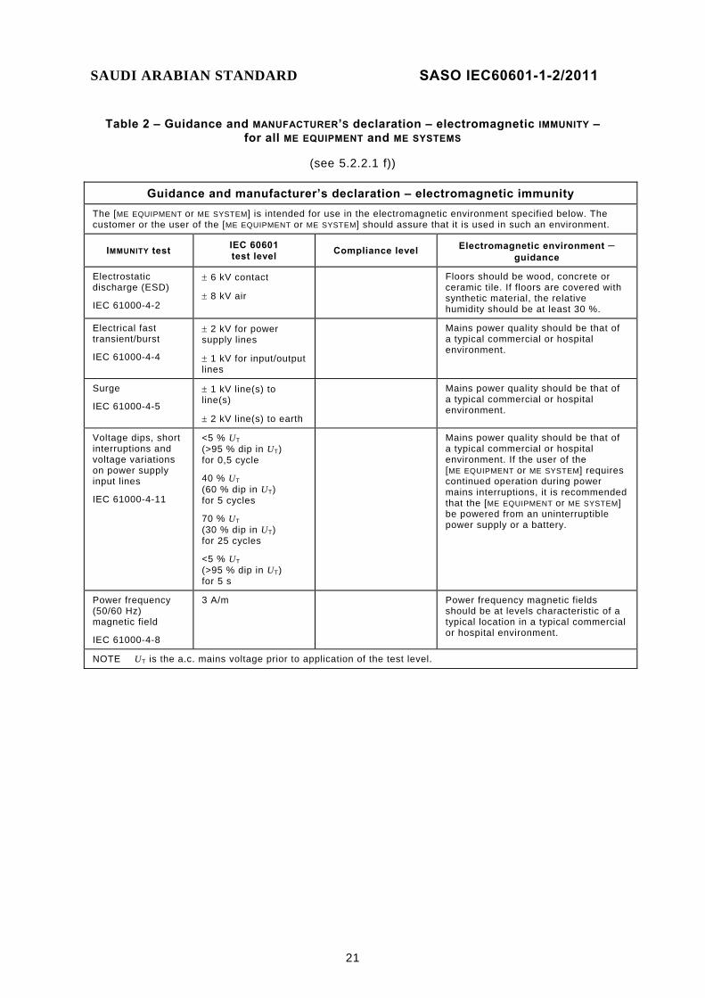
Table 2 – Guidance and MANUFACTURER’S declaration – electromagnetic IMMUNITY – for all ME EQUIPMENT and ME SYSTEMS
(see 5.2.2.1 f))
Guidance and manufacturer’s declaration – electromagnetic immunity The [ME EQUIPMENT or ME SYSTEM] is intended for use in the electromagnetic environment specified below. The customer or the user of the [ME EQUIPMENT or ME SYSTEM] should assure that it is used in such an environment.
IMMUNITY test IEC 60601 test level Compliance level Electromagnetic environment –
guidance
Electrostatic discharge (ESD)
IEC 61000-4-2
± 6 kV contact
± 8 kV air
Floors should be wood, concrete or ceramic tile. If floors are covered with synthetic material, the relative humidity should be at least 30 %.
Electrical fast transient/burst
IEC 61000-4-4
± 2 kV for power supply lines
± 1 kV for input/output lines
Mains power quality should be that of a typical commercial or hospital environment.
Surge
IEC 61000-4-5
± 1 kV line(s) to line(s)
± 2 kV line(s) to earth
Mains power quality should be that of a typical commercial or hospital environment.
Voltage dips, short interruptions and voltage variations on power supply input lines
IEC 61000-4-11
<5 % UT (>95 % dip in UT) for 0,5 cycle
40 % UT (60 % dip in UT) for 5 cycles
70 % UT (30 % dip in UT) for 25 cycles
<5 % UT (>95 % dip in UT) for 5 s
Mains power quality should be that of a typical commercial or hospital environment. If the user of the [ME EQUIPMENT or ME SYSTEM] requires continued operation during power mains interruptions, it is recommended that the [ME EQUIPMENT or ME SYSTEM] be powered from an uninterruptible power supply or a battery.
Power frequency (50/60 Hz) magnetic field
IEC 61000-4-8
3 A/m Power frequency magnetic fields should be at levels characteristic of a typical location in a typical commercial or hospital environment.
NOTE UT is the a.c. mains voltage prior to application of the test level.
SAUDI ARABIAN STANDARD SASO IEC60601-1-2/2011
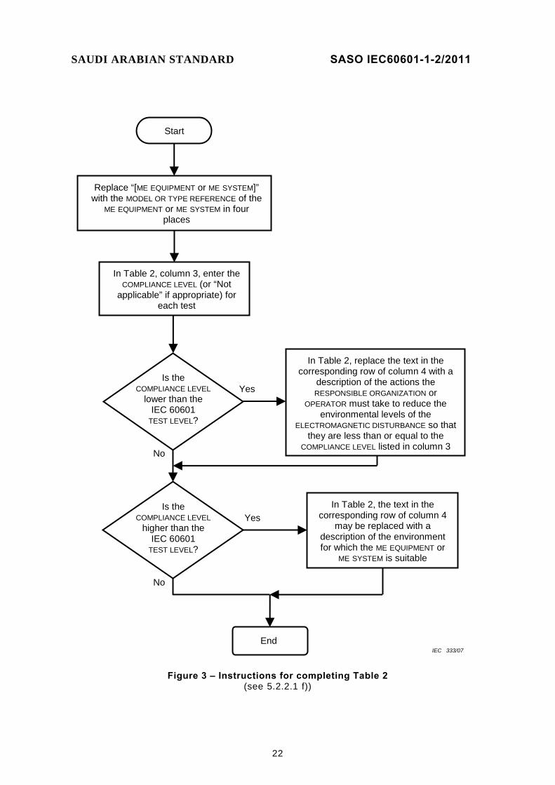
22
In Table 2, column 3, enter the COMPLIANCE LEVEL (or “Not
applicable” if appropriate) for each test
Replace “[ME EQUIPMENT or ME SYSTEM]” with the MODEL OR TYPE REFERENCE of the
ME EQUIPMENT or ME SYSTEM in four places
End
Start
Is the COMPLIANCE LEVEL
lower than the IEC 60601
TEST LEVEL?
In Table 2, replace the text in the corresponding row of column 4 with a
description of the actions the RESPONSIBLE ORGANIZATION or
OPERATOR must take to reduce the environmental levels of the
ELECTROMAGNETIC DISTURBANCE so that they are less than or equal to the
COMPLIANCE LEVEL listed in column 3
Is the COMPLIANCE LEVEL
higher than the IEC 60601
TEST LEVEL?
In Table 2, the text in the corresponding row of column 4
may be replaced with a description of the environment for which the ME EQUIPMENT or
ME SYSTEM is suitable
Yes
Yes
No
No
IEC 333/07
Figure 3 – Instructions for completing Table 2 (see 5.2.2.1 f))

SAUDI ARABIAN STANDARD SASO IEC60601-1-2/2011
23
5.2.2.2 * Requirements applicable to ME EQUIPMENT and ME SYSTEMS other than those specified for use only in a shielded location
For ME EQUIPMENT and ME SYSTEMS other than those specified for use only in a shielded location, the ACCOMPANYING DOCUMENTS shall include the following information.
The applicable tables, Table 3 and Table 5 or Table 4 and Table 6. Table 3 and Table 5 shall be used for LIFE-SUPPORTING ME EQUIPMENT and ME SYSTEMS. Table 4 and Table 6 shall be used for ME EQUIPMENT and ME SYSTEMS that are not LIFE-SUPPORTING. The tables shall be completed for the conducted and radiated RF IMMUNITY tests as specified below.3) The flowchart in Figure 4 is the requirement in step-by-step graphical form for completion of Table 3 and Table 5, and the flowchart in Figure 5 is the requirement in step-by-step graphical form for completion of Table 4 and Table 6.
a) “[ME EQUIPMENT or ME SYSTEM]” shall be replaced with the MODEL OR TYPE REFERENCE of the ME EQUIPMENT or ME SYSTEM. NOTE There are six places in Table 3 and Table 4 and four places in Table 5 and Table 6 where “[ME EQUIPMENT or ME SYSTEM]” must be replaced.
b) Column 3 of Table 3 or Table 4, as applicable, shall be filled in with the IMMUNITY COMPLIANCE LEVEL in accordance with the requirements of 5.2.2 and 6.2. If a COMPLIANCE LEVEL lower or higher than the IEC 60601 TEST LEVEL is claimed, it shall be one of the levels listed in the referenced basic EMC IMMUNITY standard unless the COMPLIANCE LEVEL is outside the range of levels listed. If the COMPLIANCE LEVEL is outside the range of levels listed in the referenced basic EMC IMMUNITY standard, the actual IMMUNITY LEVEL shall be stated, rounded to one significant digit.
c) The expressions in square brackets ([ ]) that contain V1, V2 and E1 in column 4 of Table 3 or Table 4, as applicable, and in Table 5 or Table 6, as applicable, shall be calculated, rounded to two significant digits, and the results substituted in place of the corresponding expressions. V1 and V2 are the COMPLIANCE LEVELS for the IEC 61000-4-6 test and E1 is the COMPLIANCE LEVEL for the IEC 61000-4-3 test. V1 and V2 are in V and E1 is in V/m. The value of V1 shall also be substituted for “[V1]” in the table footnote in Table 3 or Table 4, as applicable.
d) Table 5 and Table 6, as applicable, shall be completed by calculating the distance corresponding to each entry in columns 2 through 5 in Table 5 or columns 2 through 4 in Table 6, as applicable, using the equation in that column and the output power that appears in column 1 of that row. The calculated distances shall be rounded to two significant digits and entered in Table 5 or Table 6, as applicable.
e) If, according to 6.2 or the scope of the EMC basic standard, a test does not apply to the ME EQUIPMENT or ME SYSTEM, or it is not possible to perform the test on the ME EQUIPMENT or ME SYSTEM, the corresponding entries in columns 3 and 4 of Table 3 or Table 4 and the corresponding cells of Table 5 or Table 6 shall state “not applicable”.
__________ 3) See 0 for examples.
SAUDI ARABIAN STANDARD SASO IEC60601-1-2/2011
24
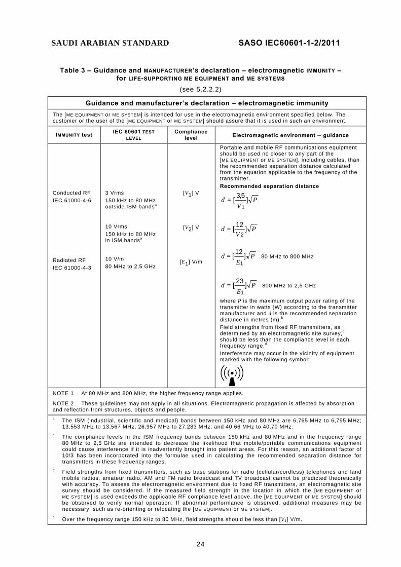
Table 3 – Guidance and MANUFACTURER’S declaration – electromagnetic IMMUNITY – for LIFE-SUPPORTING ME EQUIPMENT and ME SYSTEMS
(see 5.2.2.2)
Guidance and manufacturer’s declaration – electromagnetic immunity The [ME EQUIPMENT or ME SYSTEM] is intended for use in the electromagnetic environment specified below. The customer or the user of the [ME EQUIPMENT or ME SYSTEM] should assure that it is used in such an environment.
IMMUNITY test IEC 60601 TEST LEVEL
Compliance level Electromagnetic environment – guidance
Conducted RF IEC 61000-4-6 Radiated RF IEC 61000-4-3
3 Vrms 150 kHz to 80 MHz outside ISM bandsa 10 Vrms 150 kHz to 80 MHz in ISM bandsa
10 V/m 80 MHz to 2,5 GHz
[V1] V
[V2] V
[E1] V/m
Portable and mobile RF communications equipment should be used no closer to any part of the [ME EQUIPMENT or ME SYSTEM], including cables, than the recommended separation distance calculated from the equation applicable to the frequency of the transmitter. Recommended separation distance
PV
=d ]5,3[1
PV
=d ]12[2
PE
=d ]12[1
80 MHz to 800 MHz
PE
=d ]23[1
800 MHz to 2,5 GHz
where P is the maximum output power rating of the transmitter in watts (W) according to the transmitter manufacturer and d is the recommended separation distance in metres (m).b Field strengths from fixed RF transmitters, as determined by an electromagnetic site survey,c should be less than the compliance level in each frequency range.d Interference may occur in the vicinity of equipment marked with the following symbol:
NOTE 1 At 80 MHz and 800 MHz, the higher frequency range applies.
NOTE 2 These guidelines may not apply in all situations. Electromagnetic propagation is affected by absorption and reflection from structures, objects and people.
a The ISM (industrial, scientific and medical) bands between 150 kHz and 80 MHz are 6,765 MHz to 6,795 MHz; 13,553 MHz to 13,567 MHz; 26,957 MHz to 27,283 MHz; and 40,66 MHz to 40,70 MHz.
b The compliance levels in the ISM frequency bands between 150 kHz and 80 MHz and in the frequency range 80 MHz to 2,5 GHz are intended to decrease the likelihood that mobile/portable communications equipment could cause interference if it is inadvertently brought into patient areas. For this reason, an additional factor of 10/3 has been incorporated into the formulae used in calculating the recommended separation distance for transmitters in these frequency ranges.
c Field strengths from fixed transmitters, such as base stations for radio (cellular/cordless) telephones and land mobile radios, amateur radio, AM and FM radio broadcast and TV broadcast cannot be predicted theoretically with accuracy. To assess the electromagnetic environment due to fixed RF transmitters, an electromagnetic site survey should be considered. If the measured field strength in the location in which the [ME EQUIPMENT or ME SYSTEM] is used exceeds the applicable RF compliance level above, the [ME EQUIPMENT or ME SYSTEM] should be observed to verify normal operation. If abnormal performance is observed, additional measures may be necessary, such as re-orienting or relocating the [ME EQUIPMENT or ME SYSTEM].
d Over the frequency range 150 kHz to 80 MHz, field strengths should be less than [V1] V/m.
SAUDI ARABIAN STANDARD SASO IEC60601-1-2/2011
25
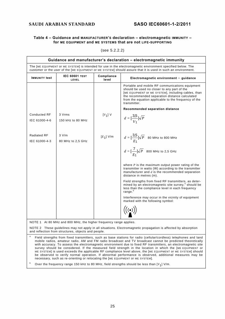
Table 4 – Guidance and MANUFACTURER’S declaration – electromagnetic IMMUNITY – for ME EQUIPMENT and ME SYSTEMS that are not LIFE-SUPPORTING
(see 5.2.2.2)
Guidance and manufacturer’s declaration – electromagnetic immunity The [ME EQUIPMENT or ME SYSTEM] is intended for use in the electromagnetic environment specified below. The customer or the user of the [ME EQUIPMENT or ME SYSTEM] should assure that it is used in such an environment.
IMMUNITY test IEC 60601 TEST LEVEL
Compliance level Electromagnetic environment – guidance
Conducted RF
IEC 61000-4-6
Radiated RF
IEC 61000-4-3
3 Vrms
150 kHz to 80 MHz
3 V/m
80 MHz to 2,5 GHz
[V1] V
[E1] V/m
Portable and mobile RF communications equipment should be used no closer to any part of the [ME EQUIPMENT or ME SYSTEM], including cables, than the recommended separation distance calculated from the equation applicable to the frequency of the transmitter.
Recommended separation distance
PV
=d ]5,3[1
PE
=d ]5,3[1
80 MHz to 800 MHz
PE
=d ]7[1
800 MHz to 2,5 GHz
where P is the maximum output power rating of the transmitter in watts (W) according to the transmitter manufacturer and d is the recommended separation distance in metres (m).
Field strengths from fixed RF transmitters, as deter-mined by an electromagnetic site survey,a should be less than the compliance level in each frequency range.b
Interference may occur in the vicinity of equipment marked with the following symbol:
NOTE 1 At 80 MHz and 800 MHz, the higher frequency range applies.
NOTE 2 These guidelines may not apply in all situations. Electromagnetic propagation is affected by absorption and reflection from structures, objects and people.
a Field strengths from fixed transmitters, such as base stations for radio (cellular/cordless) telephones and land mobile radios, amateur radio, AM and FM radio broadcast and TV broadcast cannot be predicted theoretically with accuracy. To assess the electromagnetic environment due to fixed RF transmitters, an electromagnetic site survey should be considered. If the measured field strength in the location in which the [ME EQUIPMENT or ME SYSTEM] is used exceeds the applicable RF compliance level above, the [ME EQUIPMENT or ME SYSTEM] should be observed to verify normal operation. If abnormal performance is observed, additional measures may be necessary, such as re-orienting or relocating the [ME EQUIPMENT or ME SYSTEM].
b Over the frequency range 150 kHz to 80 MHz, field strengths should be less than [V1] V/m.

SAUDI ARABIAN STANDARD SASO IEC60601-1-2/2011
26
SAUDI ARABIAN STANDARD SASO IEC60601-1-2/2011
27
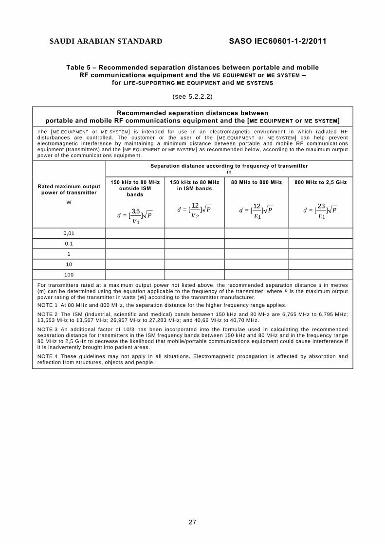
Table 5 – Recommended separation distances between portable and mobile RF communications equipment and the ME EQUIPMENT or ME SYSTEM –
for LIFE-SUPPORTING ME EQUIPMENT and ME SYSTEMS
(see 5.2.2.2)
Recommended separation distances between portable and mobile RF communications equipment and the [ME EQUIPMENT or ME SYSTEM]
The [ME EQUIPMENT or ME SYSTEM] is intended for use in an electromagnetic environment in which radiated RF disturbances are controlled. The customer or the user of the [ME EQUIPMENT or ME SYSTEM] can help prevent electromagnetic interference by maintaining a minimum distance between portable and mobile RF communications equipment (transmitters) and the [ME EQUIPMENT or ME SYSTEM] as recommended below, according to the maximum output power of the communications equipment.
Rated maximum output power of transmitter
W
Separation distance according to frequency of transmitter m
150 kHz to 80 MHzoutside ISM
bands
PV
=d ]5,3[1
150 kHz to 80 MHzin ISM bands
PV
=d ]12[2
80 MHz to 800 MHz
PE
=d ]12[1
800 MHz to 2,5 GHz
PE
=d ]23[1
0,01
0,1
1
10
100
For transmitters rated at a maximum output power not listed above, the recommended separation distance d in metres (m) can be determined using the equation applicable to the frequency of the transmitter, where P is the maximum output power rating of the transmitter in watts (W) according to the transmitter manufacturer. NOTE 1 At 80 MHz and 800 MHz, the separation distance for the higher frequency range applies.
NOTE 2 The ISM (industrial, scientific and medical) bands between 150 kHz and 80 MHz are 6,765 MHz to 6,795 MHz; 13,553 MHz to 13,567 MHz; 26,957 MHz to 27,283 MHz; and 40,66 MHz to 40,70 MHz.
NOTE 3 An additional factor of 10/3 has been incorporated into the formulae used in calculating the recommended separation distance for transmitters in the ISM frequency bands between 150 kHz and 80 MHz and in the frequency range 80 MHz to 2,5 GHz to decrease the likelihood that mobile/portable communications equipment could cause interference if it is inadvertently brought into patient areas.
NOTE 4 These guidelines may not apply in all situations. Electromagnetic propagation is affected by absorption and reflection from structures, objects and people.
SAUDI ARABIAN STANDARD SASO IEC60601-1-2/2011
28
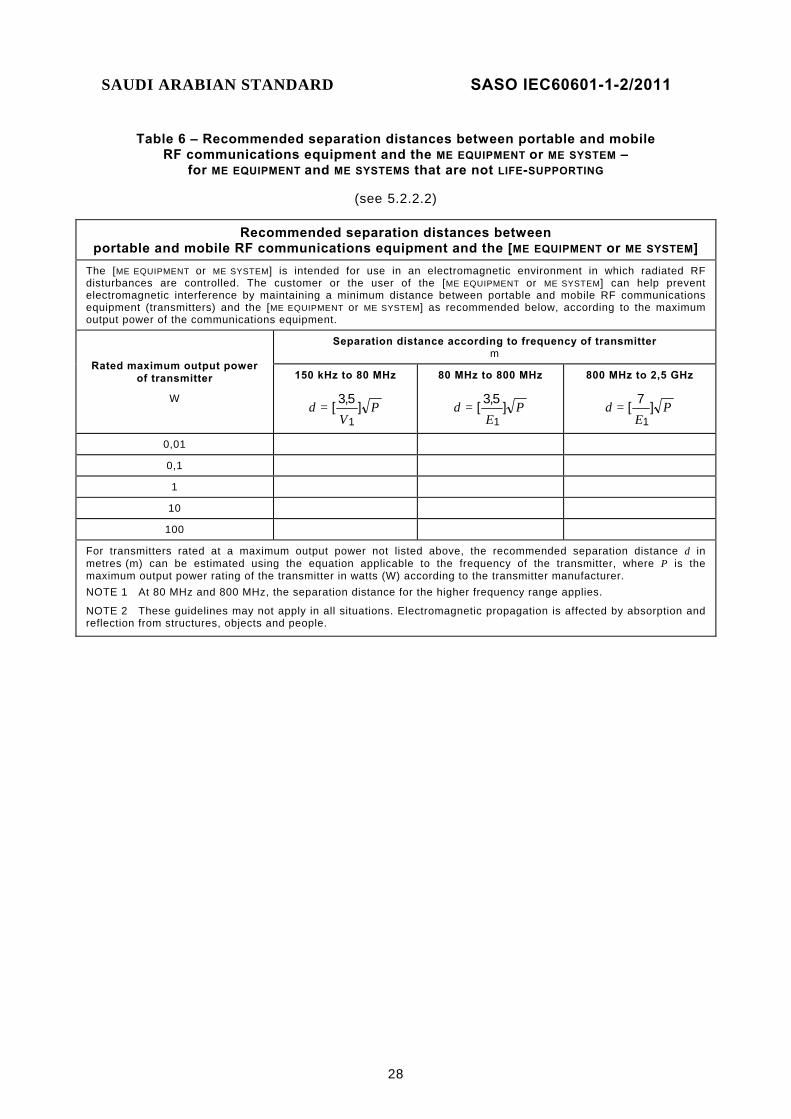
Table 6 – Recommended separation distances between portable and mobile RF communications equipment and the ME EQUIPMENT or ME SYSTEM –
for ME EQUIPMENT and ME SYSTEMS that are not LIFE-SUPPORTING
(see 5.2.2.2)
Recommended separation distances between portable and mobile RF communications equipment and the [ME EQUIPMENT or ME SYSTEM]
The [ME EQUIPMENT or ME SYSTEM] is intended for use in an electromagnetic environment in which radiated RF disturbances are controlled. The customer or the user of the [ME EQUIPMENT or ME SYSTEM] can help prevent electromagnetic interference by maintaining a minimum distance between portable and mobile RF communications equipment (transmitters) and the [ME EQUIPMENT or ME SYSTEM] as recommended below, according to the maximum output power of the communications equipment.
Rated maximum output power of transmitter
W
Separation distance according to frequency of transmitter m
150 kHz to 80 MHz
PV
=d ]5,3[1
80 MHz to 800 MHz
PE
=d ]5,3[1
800 MHz to 2,5 GHz
PE
=d ]7[1
0,01
0,1
1
10
100
For transmitters rated at a maximum output power not listed above, the recommended separation distance d in metres (m) can be estimated using the equation applicable to the frequency of the transmitter, where P is the maximum output power rating of the transmitter in watts (W) according to the transmitter manufacturer. NOTE 1 At 80 MHz and 800 MHz, the separation distance for the higher frequency range applies.
NOTE 2 These guidelines may not apply in all situations. Electromagnetic propagation is affected by absorption and reflection from structures, objects and people.
SAUDI ARABIAN STANDARD SASO IEC60601-1-2/2011
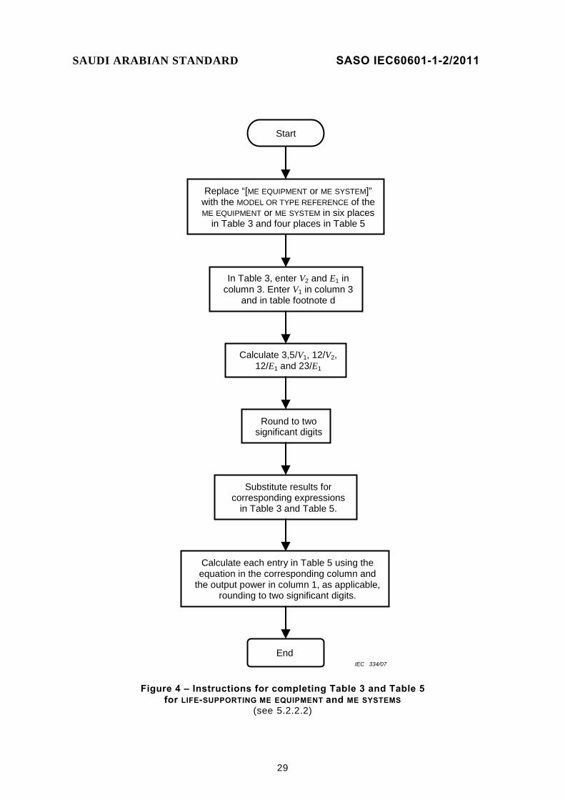
29
In Table 3, enter V2 and E1 in column 3. Enter V1 in column 3
and in table footnote d
Calculate 3,5/V1, 12/V2, 12/E1 and 23/E1
Round to two significant digits
Replace “[ME EQUIPMENT or ME SYSTEM]” with the MODEL OR TYPE REFERENCE of the ME EQUIPMENT or ME SYSTEM in six places
in Table 3 and four places in Table 5
Substitute results for corresponding expressions
in Table 3 and Table 5.
Calculate each entry in Table 5 using the equation in the corresponding column and
the output power in column 1, as applicable, rounding to two significant digits.
End
Start
IEC 334/07
Figure 4 – Instructions for completing Table 3 and Table 5 for LIFE-SUPPORTING ME EQUIPMENT and ME SYSTEMS
(see 5.2.2.2)
SAUDI ARABIAN STANDARD SASO IEC60601-1-2/2011
30

SAUDI ARABIAN STANDARD SASO IEC60601-1-2/2011
31
In Table 4, enter E1 in column 3. Enter V1 in column 3
and in table footnote b
Calculate 3,5/E1, 7/E1 and 3,5/V1
Round to two significant digits
Replace “[ME EQUIPMENT or ME SYSTEM]” with the MODEL OR TYPE REFERENCE of the ME EQUIPMENT or ME SYSTEM in six places
in Table 4 and four places in Table 6
Substitute results for corresponding expressions
in Table 4 and Table 6.
Calculate each entry in Table 6 using the equation in the corresponding column and
the output power in column 1, as applicable, rounding to two significant digits.
End
Start
IEC 335/07
Figure 5 – Instructions for completing Table 4 and Table 6 for ME EQUIPMENT and ME SYSTEMS that are not LIFE-SUPPORTING
(see 5.2.2.2)

SAUDI ARABIAN STANDARD SASO IEC60601-1-2/2011
32
5.2.2.3 Requirements applicable to ME EQUIPMENT and ME SYSTEMS specified for use only in a shielded location
For ME EQUIPMENT and ME SYSTEMS specified for use only in a shielded location, the ACCOMPANYING DOCUMENTS shall include the following information.
a) A warning that the ME EQUIPMENT or ME SYSTEM should be used only in the specified type of shielded location.
b) * If the electromagnetic radiation disturbance allowance or the mains terminal disturbance voltage allowance in 6.1.1.1 d) is used: – the following text, added to column 2 of the CISPR row of Table 1, after or below
the CISPR class: (The [ME EQUIPMENT or ME SYSTEM] in combination with the shielded location) where “[ME EQUIPMENT or ME SYSTEM]” shall be replaced with the MODEL OR TYPE REFERENCE of the ME EQUIPMENT or ME SYSTEM;
– the following text, appended to the beginning of the text in column 3 of Table 1 in the merged cell of the CISPR 11, IEC 61000-3-2 and IEC 61000-3-3 rows: The [ME EQUIPMENT or ME SYSTEM] must be used only in a shielded location with a
minimum RF shielding effectiveness and, for each cable that exits the shielded location, a minimum RF filter attenuation of [shielding effectiveness / filter attenuation specification].
where “[me equipment or me system]” shall be replaced with the model or type reference of the me equipment or me system and “[shielding effectiveness / filter attenuation specification]” shall be replaced with the specification for minimum RF shielding effectiveness and RF filter attenuation. NOTE This specification is also used in Table 7 and Table 8 (see 5.2.2.3 d)).
The specification for minimum RF shielding effectiveness and RF filter attenuation shall meet the following requirements: – the specified RF shielding effectiveness and RF filter attenuation
shall be expressed in dB, shall be rounded to the nearest integer and shall be at least 20 dB;
– the RF shielding effectiveness and RF filter attenuation specification shall include the frequency range over which the RF shielding effectiveness and RF filter attenuation apply, and this frequency range shall be at least one decade in width;
– the specified value(s) for minimum RF filter attenuation shall be identical to the specified value(s) for minimum RF shielding effectiveness in each frequency range for which they are specified;
– in frequency ranges for which the minimum RF shielding effectiveness and RF filter attenuation are not specified or are specified to be less than 20 dB, the RF shielding effectiveness and RF filter attenuation shall be assumed to be 0 dB for the purpose of this collateral standard;
– the following text, added to replace “The [ME EQUIPMENT or ME SYSTEM] is suitable” in the text in column 3 of Table 1 in the merged cell of the CISPR 11, IEC 61000-3-2 and IEC 61000-3-3 rows:
The [ME EQUIPMENT or ME SYSTEM], when installed in such a shielded location, is suitable
where “[ME EQUIPMENT or ME SYSTEM]” shall be replaced with the MODEL OR TYPE REFERENCE of the ME EQUIPMENT or ME SYSTEM;
SAUDI ARABIAN STANDARD SASO IEC60601-1-2/2011
33
– the following note, added to the bottom of Table 1: NOTE It is essential that the actual RF shielding effectiveness and filter attenuation of the shielded location be verified to ensure that they meet or exceed the specified minimum values.
c) * A specification of the EMISSIONS characteristics of other equipment allowed inside the shielded location with the ME EQUIPMENT or ME SYSTEM, a list of specific equipment allowed or a list of types of equipment prohibited (see 6.2.3.1 c) and 6.2.6.1 c)) and a recommendation that a notice containing this information be posted at the entrance(s) to the shielded location.
d) * The applicable table, Table 7 or Table 8. Table 7 shall be used for LIFE-SUPPORTING ME EQUIPMENT and ME SYSTEMS. Table 8 shall be used for ME EQUIPMENT and ME SYSTEMS that are not LIFE-SUPPORTING. The tables shall be completed as follows: 4) – “[ME EQUIPMENT or ME SYSTEM]” shall be replaced with the MODEL OR TYPE
REFERENCE of the ME EQUIPMENT or ME SYSTEM; NOTE There are six places in Table 7 and Table 8. where “[ME EQUIPMENT or ME SYSTEM]” must be replaced.
– column 3 of Table 7 or Table 8, as applicable, shall be filled in with the IMMUNITY COMPLIANCE LEVEL in accordance with the requirements of 5.2.2 and 6.2. If an IMMUNITY COMPLIANCE LEVEL lower or higher than the IEC 60601 TEST LEVEL is claimed, it shall be one of the levels listed in the referenced basic EMC IMMUNITY standard unless the COMPLIANCE level is outside the range of levels listed. If the COMPLIANCE LEVEL is outside the range of levels listed in the referenced basic EMC IMMUNITY standard, the actual IMMUNITY LEVEL shall be stated, rounded to one significant digit;
– * in column 4 of Table 7 or Table 8, as applicable, “[shielding effectiveness / filter attenuation specification]” shall be replaced with the specification for minimum RF shielding effectiveness and RF filter attenuation, which shall meet the requirements specified in b), above; “[appropriate section of ACCOMPANYING DOCUMENTS]” shall be replaced with a reference to the location in the ACCOMPANYING DOCUMENTS where the information required by 5.2.2.3 c) can be found; and “[field strength]” shall be replaced with the maximum field strength in V/m, rounded to one significant digit, of fixed RF transmitters that when attenuated by the specified minimum RF shielding effectiveness and filter attenuation, will not exceed the COMPLIANCE LEVEL for any of the frequency ranges. For calculating “[field strength]”, the COMPLIANCE LEVELS for the IEC 61000-4-6 test shall be considered to be in units of V/m;
– in table footnote b of Table 7 or table footnote a of Table 8, as applicable, “[field strength]” shall be replaced as specified above for column 4 of the table.
5.2.2.4 Requirements applicable to ME EQUIPMENT and ME SYSTEMS that intentionally apply RF energy for diagnosis or treatment
For ME EQUIPMENT and ME SYSTEMS that intentionally apply RF energy for diagnosis or treatment, the ACCOMPANYING DOCUMENTS shall include guidelines for avoiding or identifying and resolving adverse electromagnetic effects on other equipment that may result from operation of the ME EQUIPMENT or ME SYSTEM.
__________ 4) See 0 for examples.
SAUDI ARABIAN STANDARD SASO IEC60601-1-2/2011
34
5.2.2.5 Requirements applicable to ME EQUIPMENT and ME SYSTEMS that intentionally receive RF electromagnetic energy for the purpose of their operation
For ME EQUIPMENT and ME SYSTEMS that intentionally receive RF electromagnetic energy for the purpose of their operation, the ACCOMPANYING DOCUMENTS shall include the following information:
a) each frequency or frequency band of reception; the preferred frequency or frequency band, if applicable, and the bandwidth of the receiving section of the ME EQUIPMENT or ME SYSTEM in those bands;
b) a warning that the ME EQUIPMENT or ME SYSTEM may be interfered with by other equipment, even if that other equipment complies with CISPR EMISSION requirements.
5.2.2.6 Requirements applicable to ME EQUIPMENT and ME SYSTEMS that include RF transmitters
For ME EQUIPMENT and ME SYSTEMS that include RF transmitters, the ACCOMPANYING DOCUMENTS shall include each frequency or frequency band of transmission, the type and frequency characteristics of the modulation and the EFFECTIVE RADIATED POWER.
SAUDI ARABIAN STANDARD SASO IEC60601-1-2/2011
35
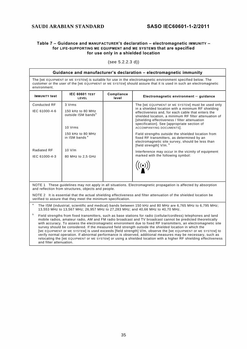
Table 7 – Guidance and MANUFACTURER’S declaration – electromagnetic IMMUNITY – for LIFE-SUPPORTING ME EQUIPMENT and ME SYSTEMS that are specified
for use only in a shielded location
(see 5.2.2.3 d))
Guidance and manufacturer’s declaration – electromagnetic immunity The [ME EQUIPMENT or ME SYSTEM] is suitable for use in the electromagnetic environment specified below. The customer or the user of the [ME EQUIPMENT or ME SYSTEM] should assure that it is used in such an electromagnetic environment.
IMMUNITY test IEC 60601 TEST LEVEL
Compliance level Electromagnetic environment – guidance
Conducted RF
IEC 61000-4-6
Radiated RF
IEC 61000-4-3
3 Vrms
150 kHz to 80 MHz outside ISM bandsa
10 Vrms
150 kHz to 80 MHz in ISM bands a
10 V/m
80 MHz to 2,5 GHz
The [ME EQUIPMENT or ME SYSTEM] must be used only in a shielded location with a minimum RF shielding effectiveness and, for each cable that enters the shielded location, a minimum RF filter attenuation of [shielding effectiveness / filter attenuation specification]. See [appropriate section of ACCOMPANYING DOCUMENTS].
Field strengths outside the shielded location from fixed RF transmitters, as determined by an electromagnetic site survey, should be less than [field strength] V/m. b
Interference may occur in the vicinity of equipment marked with the following symbol:
NOTE 1 These guidelines may not apply in all situations. Electromagnetic propagation is affected by absorption and reflection from structures, objects and people.
NOTE 2 It is essential that the actual shielding effectiveness and filter attenuation of the shielded location be verified to assure that they meet the minimum specification.
a The ISM (industrial, scientific and medical) bands between 150 kHz and 80 MHz are 6,765 MHz to 6,795 MHz; 13,553 MHz to 13,567 MHz; 26,957 MHz to 27,283 MHz; and 40,66 MHz to 40,70 MHz.
b Field strengths from fixed transmitters, such as base stations for radio (cellular/cordless) telephones and land mobile radios, amateur radio, AM and FM radio broadcast and TV broadcast cannot be predicted theoretically with accuracy. To assess the electromagnetic environment due to fixed RF transmitters, an electromagnetic site survey should be considered. If the measured field strength outside the shielded location in which the [ME EQUIPMENT or ME SYSTEM] is used exceeds [field strength] V/m, observe the [ME EQUIPMENT or ME SYSTEM] to verify normal operation. If abnormal performance is observed, additional measures may be necessary, such as relocating the [ME EQUIPMENT or ME SYSTEM] or using a shielded location with a higher RF shielding effectiveness and filter attenuation.
SAUDI ARABIAN STANDARD SASO IEC60601-1-2/2011
36
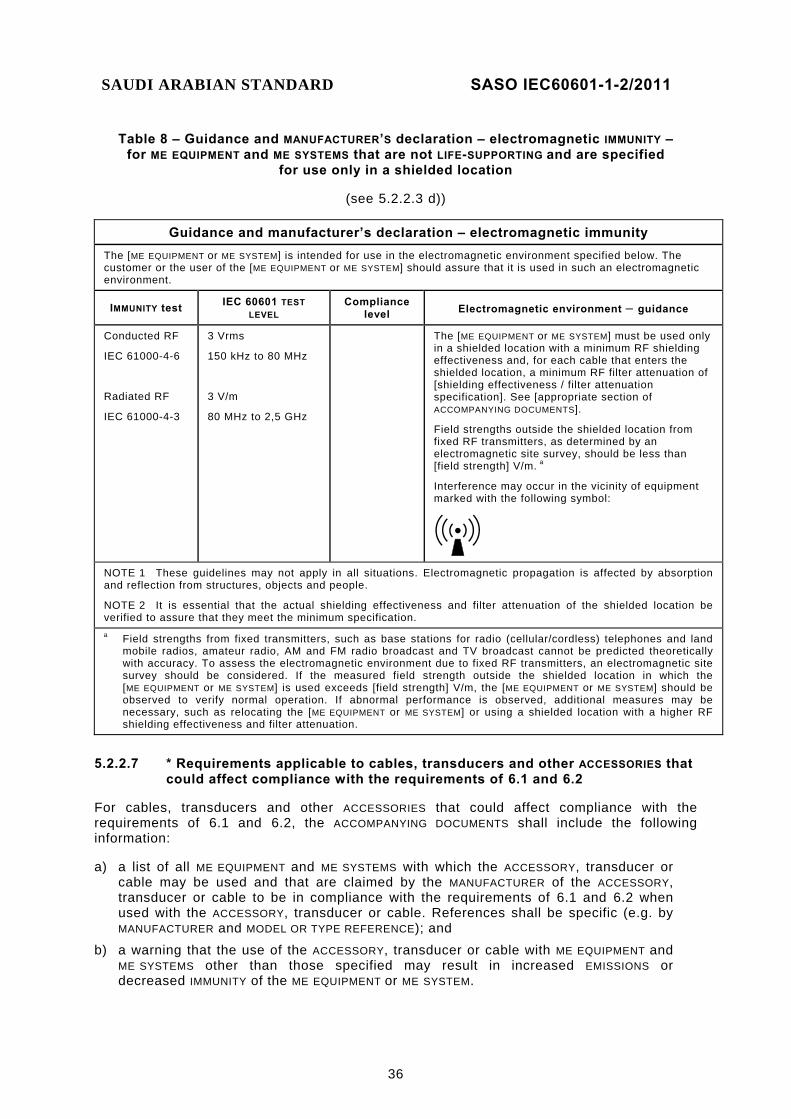
Table 8 – Guidance and MANUFACTURER’S declaration – electromagnetic IMMUNITY – for ME EQUIPMENT and ME SYSTEMS that are not LIFE-SUPPORTING and are specified
for use only in a shielded location
(see 5.2.2.3 d))
Guidance and manufacturer’s declaration – electromagnetic immunity The [ME EQUIPMENT or ME SYSTEM] is intended for use in the electromagnetic environment specified below. The customer or the user of the [ME EQUIPMENT or ME SYSTEM] should assure that it is used in such an electromagnetic environment.
IMMUNITY test IEC 60601 TEST LEVEL
Compliance level Electromagnetic environment – guidance
Conducted RF
IEC 61000-4-6
Radiated RF
IEC 61000-4-3
3 Vrms
150 kHz to 80 MHz
3 V/m
80 MHz to 2,5 GHz
The [ME EQUIPMENT or ME SYSTEM] must be used only in a shielded location with a minimum RF shielding effectiveness and, for each cable that enters the shielded location, a minimum RF filter attenuation of [shielding effectiveness / filter attenuation specification]. See [appropriate section of ACCOMPANYING DOCUMENTS].
Field strengths outside the shielded location from fixed RF transmitters, as determined by an electromagnetic site survey, should be less than [field strength] V/m. a
Interference may occur in the vicinity of equipment marked with the following symbol:
NOTE 1 These guidelines may not apply in all situations. Electromagnetic propagation is affected by absorption and reflection from structures, objects and people.
NOTE 2 It is essential that the actual shielding effectiveness and filter attenuation of the shielded location be verified to assure that they meet the minimum specification.
a Field strengths from fixed transmitters, such as base stations for radio (cellular/cordless) telephones and land mobile radios, amateur radio, AM and FM radio broadcast and TV broadcast cannot be predicted theoretically with accuracy. To assess the electromagnetic environment due to fixed RF transmitters, an electromagnetic site survey should be considered. If the measured field strength outside the shielded location in which the [ME EQUIPMENT or ME SYSTEM] is used exceeds [field strength] V/m, the [ME EQUIPMENT or ME SYSTEM] should be observed to verify normal operation. If abnormal performance is observed, additional measures may be necessary, such as relocating the [ME EQUIPMENT or ME SYSTEM] or using a shielded location with a higher RF shielding effectiveness and filter attenuation.
5.2.2.7 * Requirements applicable to cables, transducers and other ACCESSORIES that could affect compliance with the requirements of 6.1 and 6.2
For cables, transducers and other ACCESSORIES that could affect compliance with the requirements of 6.1 and 6.2, the ACCOMPANYING DOCUMENTS shall include the following information:
a) a list of all ME EQUIPMENT and ME SYSTEMS with which the ACCESSORY, transducer or cable may be used and that are claimed by the MANUFACTURER of the ACCESSORY, transducer or cable to be in compliance with the requirements of 6.1 and 6.2 when used with the ACCESSORY, transducer or cable. References shall be specific (e.g. by MANUFACTURER and MODEL OR TYPE REFERENCE); and
b) a warning that the use of the ACCESSORY, transducer or cable with ME EQUIPMENT and ME SYSTEMS other than those specified may result in increased EMISSIONS or decreased IMMUNITY of the ME EQUIPMENT or ME SYSTEM.

SAUDI ARABIAN STANDARD SASO IEC60601-1-2/2011
37
5.2.2.8 Requirements applicable to LARGE, PERMANENTLY-INSTALLED ME EQUIPMENT and ME SYSTEMS
For LARGE, PERMANENTLY-INSTALLED ME EQUIPMENT and ME SYSTEMS for which the exemption specified in 6.2.3.2 i) is used, the ACCOMPANYING DOCUMENTS shall include the following information:
a) a statement that an exemption has been used and that the ME EQUIPMENT or ME SYSTEM has not been tested for radiated RF IMMUNITY over the entire frequency range 80 MHz to 2,5 GHz;
b) a warning that the ME EQUIPMENT or ME SYSTEM has been tested for radiated RF IMMUNITY only at selected frequencies; and
c) * a list of the transmitters or equipment used as RF test sources and the frequency and modulation characteristics of each source.
5.2.2.9 Requirements applicable to ME EQUIPMENT and ME SYSTEMS found to have no ESSENTIAL PERFORMANCE
a) For ME EQUIPMENT and ME SYSTEMS found to have no ESSENTIAL PERFORMANCE and which were not tested for IMMUNITY or for which the IMMUNITY compliance criteria were considered to allow all DEGRADATIONS, the ACCOMPANYING DOCUMENTS shall include, instead of the information specified in 5.2.2.1 e) and f), 5.2.2.2, 5.2.2.3 c) and d), and 5.2.2.8, a statement that the ME EQUIPMENT or ME SYSTEM was not tested for IMMUNITY to ELECTROMAGNETIC DISTURBANCES.
b) For ME EQUIPMENT and ME SYSTEMS found to have no ESSENTIAL PERFORMANCE and for which FUNCTIONS were tested for IMMUNITY and the IMMUNITY compliance criteria were considered to apply to all DEGRADATIONS, the ACCOMPANYING DOCUMENTS shall include information applicable to the ME EQUIPMENT or ME SYSTEM as specified in 5.2.2.1 through 5.2.2.8.
5.2.2.10 * Requirements applicable to TYPE A PROFESSIONAL ME EQUIPMENT and ME SYSTEMS
For TYPE A PROFESSIONAL ME EQUIPMENT and ME SYSTEMS intended for use in domestic establishments or connection to the PUBLIC MAINS NETWORK (see 6.1.1.1 f)), the ACCOMPANYING DOCUMENTS shall include a justification for not complying with the CISPR 11 group 2 Class B electromagnetic radiation disturbance limit at the third harmonic of the fundamental frequency of the ME EQUIPMENT or ME SYSTEM. This justification shall be based on significant physical, technological or physiological limitations that prevent compliance. The ACCOMPANYING DOCUMENTS shall also include a justification why the ME EQUIPMENT or ME SYSTEM needs to be used in domestic establishments or connected to the PUBLIC MAINS NETWORK.
Check compliance with the requirements of 5.2.2 by inspection.

SAUDI ARABIAN STANDARD SASO IEC60601-1-2/2011
38
6 ELECTROMAGNETIC COMPATIBILITY
6.1 EMISSIONS
6.1.1 Protection of radio services
6.1.1.1 * Requirements
ME EQUIPMENT and ME SYSTEMS, except as specified in a) through c) below, shall be classified as group 1 or group 2 and Class A or Class B in accordance with CISPR 11, based on their INTENDED USE, as specified by the MANUFACTURER, using the guidelines in 0. ME EQUIPMENT and ME SYSTEMS shall comply with CISPR requirements, based upon their classification, with the exceptions and clarifications specified in d), e), and f) below.
a) * Simple electrical components ME EQUIPMENT containing only simple electrical components like motors and switches and not utilizing any electronic circuitry that generates or uses frequencies above 9 kHz (e.g. some dental drills, some ventilators, some operating tables) may be classified in accordance with CISPR 14-1. Classification to CISPR 14-1, however, is limited to stand-alone ME EQUIPMENT and is not applicable to ME SYSTEMS or subsystems.
b) Lighting equipment Lighting equipment used in medical applications (e.g. equipment for illumination of X-ray films, lighting devices for operating theatres) may be classified in accordance with CISPR 15. Classification to CISPR 15, however, is limited to stand-alone ME EQUIPMENT and is not applicable to ME SYSTEMS or subsystems.
c) * INFORMATION TECHNOLOGY EQUIPMENT (ITE) ITE connected to ME EQUIPMENT and ME SYSTEMS may be classified in accordance with CISPR 22 with the following restriction: CISPR 22 Class B equipment may be used with CISPR 11 Class A or Class B ME SYSTEMS, but CISPR 22 Class A equipment may only be used with CISPR 11 Class A ME SYSTEMS. See Annex D.
d) * ME EQUIPMENT and ME SYSTEMS specified for use only in a shielded location – For ME EQUIPMENT and ME SYSTEMS that are specified for use only in a shielded
location, the electromagnetic radiation disturbance limits of CISPR 11 may be increased, when tests are performed on a test site, by an amount up to the applicable specified value of minimum RF shielding effectiveness, provided the minimum RF shielding effectiveness specification meets the requirements specified in 5.2.2.3 b).
– For ME EQUIPMENT and ME SYSTEMS that are specified for use only in a shielded location, the mains terminal disturbance voltage limits of CISPR 11 may be increased, when tests are performed on a test site, by an amount up to the applicable specified value of minimum RF filter attenuation for all cables that exit the shielded location, provided the minimum RF filter attenuation specification meets the requirements specified in 5.2.2.3 b).
SAUDI ARABIAN STANDARD SASO IEC60601-1-2/2011
39
e) * ME EQUIPMENT and ME SYSTEMS that include radio equipment
ME EQUIPMENT and ME SYSTEMS that include radio equipment and have been tested and found to comply with applicable national radio regulations are exempt from testing to CISPR ELECTROMAGNETIC DISTURBANCE requirements, provided the EMISSIONS limits of the applicable national radio regulations are less than or equal to the corresponding applicable CISPR ELECTROMAGNETIC DISTURBANCE limits. ME EQUIPMENT and ME SYSTEMS that include RF transmitters are exempt from the EMISSIONS requirements of this collateral standard in the dedicated transmission band of the transmitter. Otherwise, and for ME EQUIPMENT and ME SYSTEMS intended only for countries with no national radio regulations, the EMISSIONS requirements of this collateral standard shall apply.
f) * TYPE A PROFESSIONAL ME EQUIPMENT and ME SYSTEMS
CISPR 11 group 2 PROFESSIONAL ME EQUIPMENT and ME SYSTEMS that are intended for use in domestic establishments or connection to the PUBLIC MAINS NETWORK shall comply with CISPR 11 group 2 Class B, with the exception that the third harmonic of the fundamental frequency of the ME EQUIPMENT or ME SYSTEM may comply with the CISPR 11 group 2 Class A electromagnetic radiation disturbance limit, provided this is justified based on:
– significant physical, technological or physiological limitations that prevent compliance with the CISPR 11 group 2 Class B electromagnetic radiation disturbance limit at the third harmonic of the fundamental frequency of the ME EQUIPMENT or ME SYSTEM; and
– the need for the use of the ME EQUIPMENT or ME SYSTEM in domestic establishments or connected to the PUBLIC MAINS NETWORK.
(See 5.2.1.4 and 5.2.2.10.) g) Documentation of the test
The documentation of the test shall include the test methods used to verify compliance with the requirements of this subclause and justification for any allowances of this collateral standard used. This documentation shall include a description of the ME EQUIPMENT or ME SYSTEM under test, test equipment and test set-up, settings and mode(s) of the ME EQUIPMENT or ME SYSTEM, cable layout, and all PATIENT physiological, ACCESSORY and subsystem simulators used.
Check compliance by application of the tests in 6.1.1.2.
6.1.1.2 Tests
CISPR test methods shall be used, with the clarifications and exceptions specified in a), b) and c) below.
a) * PATIENT cables
PATIENT-coupled cables are considered interconnecting cables in accordance with the requirements of CISPR 11. Any PATIENT-coupled cable termination used is to be described in the documentation of the test. If simulated PATIENT physiological signals are required to simulate normal operation of the ME EQUIPMENT or ME SYSTEM, they are to be provided. The PATIENT coupling point is not to have an intentional conductive or capacitive connection to earth during testing. Unintentional capacitance between the PATIENT coupling point and earth should be no greater than 250 pF.
b) * Subsystems
Compliance with the requirements of CISPR 11 may be demonstrated by testing each subsystem of an ME SYSTEM, provided that normal operating conditions are simulated.
SAUDI ARABIAN STANDARD SASO IEC60601-1-2/2011
40
When ME EQUIPMENT is being evaluated that interacts with other equipment to form an ME SYSTEM, then the evaluation may be carried out using either additional equipment to represent the total ME SYSTEM or with the use of simulators.
c) LARGE, PERMANENTLY-INSTALLED ME EQUIPMENT and ME SYSTEMS
LARGE, PERMANENTLY-INSTALLED ME EQUIPMENT and ME SYSTEMS that are constructed in such a way that simulated operation of subsystems is not feasible may be type tested at the premises of a typical RESPONSIBLE ORGANIZATION or OPERATOR in accordance with Clause 5 “Limits of electromagnetic disturbances,” and 11.2 “Equipment in small-scale production” of CISPR 11 [1].5)
6.1.2 * Protection of other equipment from low-frequency magnetic fields
No requirements apply.
6.1.3 Protection of the PUBLIC MAINS NETWORK
6.1.3.1 Harmonic distortion
6.1.3.1.1 * Requirements
ME EQUIPMENT and ME SYSTEMS with a RATED input current up to and including 16 A per phase and that are intended to be connected to the PUBLIC MAINS NETWORK shall comply with the requirements of IEC 61000-3-2. If ME EQUIPMENT or an ME SYSTEM has both long-time and momentary current ratings, the higher of the two ratings shall be used in determining the applicability of IEC 61000-3-2.
Check compliance by application of the tests in 6.1.3.1.2.
6.1.3.1.2 Tests The test methods and test equipment specified by IEC 61000-3-2 shall apply.
6.1.3.2 Voltage fluctuations and flicker
6.1.3.2.1 * Requirements
ME EQUIPMENT and ME SYSTEMS with a RATED input current up to and including 16 A per phase and that are intended to be connected to the PUBLIC MAINS NETWORK shall comply with the requirements of IEC 61000-3-3. If ME EQUIPMENT or an ME SYSTEM has both long-time and momentary current ratings, the higher of the two RATINGS shall be used in determining the applicability of IEC 61000-3-3.
Check compliance by application of the tests in 6.1.3.2.2.
6.1.3.2.2 Tests The test methods and test equipment specified by IEC 61000-3-3 shall apply.
__________ 5) The figures in square brackets refer to the Bibliography.

SAUDI ARABIAN STANDARD SASO IEC60601-1-2/2011
41
6.2 IMMUNITY
6.2.1 * General
6.2.1.1 * IMMUNITY TEST LEVELS
Subclause 6.2 specifies IMMUNITY requirements that are appropriate for ME EQUIPMENT and ME SYSTEMS intended for use in a typical health care ELECTROMAGNETIC ENVIRONMENT.
NOTE 1 For information concerning ELECTROMAGNETIC ENVIRONMENTS, refer to 0 and the Bibliography.
Until limits are developed for other environments, the requirements of 6.2 shall apply to ME EQUIPMENT and ME SYSTEMS used in all environments. When the expected electromagnetic characteristics of the INTENDED USE environment justify higher IMMUNITY TEST LEVELS, these higher IMMUNITY TEST LEVELS shall take precedence. Lower IMMUNITY COMPLIANCE LEVELS are allowed provided they are justified based on significant physical, technological or physiological limitations (see 5.2.2.1 e)).
NOTE 2 Writers of particular standards should refer to item a) of Clause A.18 for guidance regarding this allowance.
6.2.1.2 Documentation of the test
The documentation of the test shall include the test methods used to verify compliance with the requirements of this subclause and justification for any allowances of this collateral standard used. This documentation shall include a description of the ME EQUIPMENT or ME SYSTEM under test, details of the compliance criteria used, test equipment and test set-up, settings and mode(s) of the ME EQUIPMENT or ME SYSTEM, cable layout and all PATIENT physiological, ACCESSORY and subsystem simulators used.
6.2.1.3 Operating mode and configuration
During IMMUNITY testing, each FUNCTION of the ME EQUIPMENT or ME SYSTEM that is associated with BASIC SAFETY or ESSENTIAL PERFORMANCE shall be tested in the mode that is most critical from a PATIENT outcome perspective, using equipment options, cable layout and ACCESSORIES in a typical configuration, consistent with NORMAL USE. If the ME EQUIPMENT or ME SYSTEM is not RATED for continuous duty, the operating mode may instead be selected such that reliable operation is obtained for the applicable test duration.
6.2.1.4 * Electrical equipment that is not ME EQUIPMENT
Electrical equipment that is not ME EQUIPMENT and that is supplied as part of an ME SYSTEM is exempt from the IMMUNITY testing requirements of this collateral standard provided all of the following conditions are met (see also 0):
– the electrical equipment that is not ME EQUIPMENT complies with applicable international IMMUNITY standards;6)
– both the EMISSIONS and IMMUNITY of electrical equipment that is not ME EQUIPMENT and that is supplied as part of an ME SYSTEM have been determined not to adversely affect the BASIC SAFETY or ESSENTIAL PERFORMANCE of the ME SYSTEM.
__________ 6) For example, see CISPR 24 [2] for ITE and IEC 61326-1 [9] for measurement, control and laboratory
equipment.

SAUDI ARABIAN STANDARD SASO IEC60601-1-2/2011
42
6.2.1.5 * PATIENT-COUPLED ME EQUIPMENT and ME SYSTEMS
PATIENT-COUPLED ME EQUIPMENT and ME SYSTEMS shall be tested so that the PATIENT coupling point is within the test environment. The PATIENT coupling point shall not have an intentional conductive or capacitive connection to earth during testing, except as otherwise specified in a subclause of this collateral standard. Unintentional capacitance between the PATIENT coupling point and earth should be no greater than 250 pF.
6.2.1.6 * Variable gain
ME EQUIPMENT and ME SYSTEMS that incorporate a variable gain shall be tested at the highest gain setting that allows proper operation.
If this requirement can be met with the normal software of the ME EQUIPMENT or ME SYSTEM, the test shall be performed using the normal software. If this requirement cannot be met using the normal software of the ME EQUIPMENT or ME SYSTEM, a method shall be provided to implement this operational mode. The use of special software may be required. If special software is used, it shall not inhibit changes in gain that may occur as a result of testing.
6.2.1.7 * PATIENT simulation
If simulated PATIENT physiological signals are required to verify normal operation of the ME EQUIPMENT or ME SYSTEM, they shall be provided during IMMUNITY testing. The simulator used shall not provide an intentional conductive or capacitive connection to earth during testing, except as otherwise specified in a subclause of this collateral standard. Unintentional capacitance between the PATIENT coupling point and earth should be no greater than 250 pF. Prior to the beginning of the test, the simulated signal shall be adjusted as follows:
• For ME EQUIPMENT and ME SYSTEMS without a manual sensitivity adjustment, the simulated PATIENT physiological signal shall be set to the lowest amplitude or value consistent with normal operation as specified by the MANUFACTURER. If this minimum amplitude or value is specified by the MANUFACTURER, it shall be included in instructions for use as specified in 5.2.1.3. If the lowest amplitude or value consistent with normal operation is not specified by the MANUFACTURER, then the simulated PATIENT physiological signal shall be set to the minimum amplitude or value at which the ME EQUIPMENT or ME SYSTEM operates as intended.
• For ME EQUIPMENT and ME SYSTEMS with a manual sensitivity adjustment, the simulated PATIENT physiological signal shall be set according to the MANUFACTURER’S sensitivity adjustment guidelines with the ME EQUIPMENT or ME SYSTEM operating at its most sensitive setting. If simulated PATIENT physiological signals are not required to verify normal operation of the ME EQUIPMENT or ME SYSTEM, the ME EQUIPMENT or ME SYSTEM shall be tested as specified in 6.2.1.3 without PATIENT physiological signal simulation.
6.2.1.8 * Testing of normally non-observable FUNCTIONS
If a FUNCTION associated with ESSENTIAL PERFORMANCE (e.g. HIGH PRIORITY and MEDIUM PRIORITY ALARM CONDITIONS) cannot normally be observed or verified during the test, a method shall be provided (e.g. display of internal parameters) for determining compliance. The use of special software or hardware may be needed.

SAUDI ARABIAN STANDARD SASO IEC60601-1-2/2011
43
6.2.1.9 * Subsystems
Compliance with the requirements of this collateral standard may be demonstrated by testing each subsystem of an ME SYSTEM, provided that normal operating conditions are simulated.
When ME EQUIPMENT is being evaluated that interacts with other equipment to form an ME SYSTEM, then the evaluation may be carried out using either additional equipment to represent the total ME SYSTEM or with the use of simulators.
6.2.1.10 * Compliance criteria
Under the test conditions specified in 6.2, the ME EQUIPMENT or ME SYSTEM shall be able to provide the BASIC SAFETY and ESSENTIAL PERFORMANCE. The following DEGRADATIONS, if associated with BASIC SAFETY and ESSENTIAL PERFORMANCE, shall not be allowed: – component failures; – changes in programmable parameters; – reset to factory defaults (MANUFACTURER’S presets); – change of operating mode; – false alarms; – cessation or interruption of any intended operation, even if accompanied by an alarm; – initiation of any unintended operation, including unintended or uncontrolled motion, even
if accompanied by an alarm; – error of a displayed numerical value sufficiently large to affect diagnosis or treatment; – noise on a waveform in which the noise would interfere with diagnosis, treatment or
monitoring; – artefact or distortion in an image in which the artefact would interfere with diagnosis,
treatment or monitoring; – failure of automatic diagnosis or treatment ME EQUIPMENT and ME SYSTEMS to diagnose or
treat, even if accompanied by an alarm.
For ME EQUIPMENT and ME SYSTEMS with multiple FUNCTIONS, the criteria apply to each FUNCTION, parameter and channel.
The ME EQUIPMENT or ME SYSTEM may exhibit DEGRADATION of performance (e.g. deviation from MANUFACTURER’S specifications) that does not affect BASIC SAFETY or ESSENTIAL PERFORMANCE.
6.2.1.11 * ME EQUIPMENT and ME SYSTEMS that include radio equipment
For ME EQUIPMENT and ME SYSTEMS that include radio equipment and in which the IMMUNITY of the radio communication FUNCTION has been tested and found to comply with applicable national radio regulations, the radio equipment is exempt from testing to the IMMUNITY requirements of this collateral standard, provided the IMMUNITY requirements of the applicable national radio regulations for the exempted IMMUNITY test are greater than or equal to those determined in accordance with 6.2.1.1. Otherwise, and for ME EQUIPMENT and ME SYSTEMS intended only for countries with no national radio regulations, the IMMUNITY requirements of this collateral standard shall apply.

SAUDI ARABIAN STANDARD SASO IEC60601-1-2/2011
44
6.2.2 ELECTROSTATIC DISCHARGE (ESD)
6.2.2.1 * Requirements
ME EQUIPMENT and ME SYSTEMS shall comply with the requirements of 6.2.1.10 at IMMUNITY TEST LEVELS of ± 2 kV, ± 4 kV and ± 8 kV for air discharge and ± 2 kV, ± 4 kV and ± 6 kV for contact discharge.
Check compliance by application of the tests in 6.2.2.2. Evaluate the response of the ME EQUIPMENT or ME SYSTEM during and after these tests in accordance with 6.2.1.10, considering each discharge individually.
6.2.2.2 Tests
The test methods and equipment specified by IEC 61000-4-2 apply, with the following modifications:
a) * The time between discharges is set to an initial value of 1 s. Longer time between discharges may be required in order to be able to distinguish between a response caused by a single discharge and a response caused by a number of discharges.
b) * Contact discharges are applied to conductive ACCESSIBLE PARTS of the ME EQUIPMENT or ME SYSTEM and coupling planes.
c) * Air discharges are applied to non-conductive ACCESSIBLE PARTS of the ME EQUIPMENT or ME SYSTEM and conductive non-accessible portions of ACCESSIBLE PARTS. If the ME EQUIPMENT or ME SYSTEM is labelled with the IEC 60417-5134 (2003-04) symbol adjacent to a connector, that connector is exempt from this testing (see 5.1.2 and 5.2.1.2).
d) * ME EQUIPMENT and ME SYSTEMS that are INTERNALLY POWERED, are of CLASS II or contain circuitry isolated from protective earth are tested in such a way as to ensure that there is no appreciable charge retention between individual test discharges. The potential on the ME EQUIPMENT or ME SYSTEM may be equalized with that of the ground plane, between individual test discharges, by temporarily grounding it through two 470 kΩ resistors connected in series. This potential equalization connection shall be disconnected and moved away from the ME EQUIPMENT or ME SYSTEM during application of a test discharge.
e) The test may be performed with the ME EQUIPMENT or ME SYSTEM powered at any one of its NOMINAL input voltages and frequencies.
6.2.3 Radiated RF electromagnetic fields
6.2.3.1 * Requirements a) * General
ME EQUIPMENT and ME SYSTEMS that are not LIFE-SUPPORTING ME EQUIPMENT and ME SYSTEMS, except as specified in c) below or in the EXCLUSION BAND as specified in d) below, shall comply with the requirements of 6.2.1.10 at an IMMUNITY TEST LEVEL of 3 V/m over the frequency range 80 MHz to 2,5 GHz.
b) * LIFE-SUPPORTING ME EQUIPMENT and ME SYSTEMS LIFE-SUPPORTING ME EQUIPMENT and ME SYSTEMS, except as specified in c) below or within the EXCLUSION BAND as specified in d) below, shall comply with the requirements of 6.2.1.10 at an IMMUNITY TEST LEVEL of 10 V/m over the frequency range 80 MHz to 2,5 GHz.
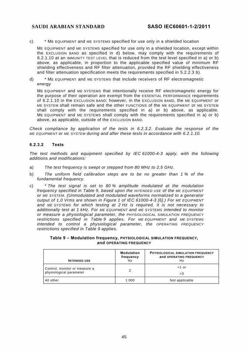
SAUDI ARABIAN STANDARD SASO IEC60601-1-2/2011
45
c) * ME EQUIPMENT and ME SYSTEMS specified for use only in a shielded location ME EQUIPMENT and ME SYSTEMS specified for use only in a shielded location, except within the EXCLUSION BAND as specified in d) below, may comply with the requirements of 6.2.1.10 at an IMMUNITY TEST LEVEL that is reduced from the test level specified in a) or b) above, as applicable, in proportion to the applicable specified value of minimum RF shielding effectiveness and RF filter attenuation, provided the RF shielding effectiveness and filter attenuation specification meets the requirements specified in 5.2.2.3 b).
d) * ME EQUIPMENT and ME SYSTEMS that include receivers of RF electromagnetic energy ME EQUIPMENT and ME SYSTEMS that intentionally receive RF electromagnetic energy for the purpose of their operation are exempt from the ESSENTIAL PERFORMANCE requirements of 6.2.1.10 in the EXCLUSION BAND; however, in the EXCLUSION BAND, the ME EQUIPMENT or ME SYSTEM shall remain safe and the other FUNCTIONS of the ME EQUIPMENT or ME SYSTEM shall comply with the requirements specified in a) or b) above, as applicable. ME EQUIPMENT and ME SYSTEMS shall comply with the requirements specified in a) or b) above, as applicable, outside of the EXCLUSION BAND.
Check compliance by application of the tests in 6.2.3.2. Evaluate the response of the ME EQUIPMENT or ME SYSTEM during and after these tests in accordance with 6.2.1.10.
6.2.3.2 Tests
The test methods and equipment specified by IEC 61000-4-3 apply, with the following additions and modifications:
a) The test frequency is swept or stepped from 80 MHz to 2,5 GHz. b) The uniform field calibration steps are to be no greater than 1 % of the
fundamental frequency. c) * The test signal is set to 80 % amplitude modulated at the modulation
frequency specified in Table 9, based upon the INTENDED USE of the ME EQUIPMENT or ME SYSTEM. (Unmodulated and modulated waveforms normalized to a generator output of 1,0 Vrms are shown in Figure 1 of IEC 61000-4-3 [6].) For ME EQUIPMENT and ME SYSTEMS for which testing at 2 Hz is required, it is not necessary to additionally test at 1 kHz. For ME EQUIPMENT and ME SYSTEMS intended to monitor or measure a physiological parameter, the PHYSIOLOGICAL SIMULATION FREQUENCY restrictions specified in Table 9 applies. For ME EQUIPMENT and ME SYSTEMS intended to control a physiological parameter, the OPERATING FREQUENCY restrictions specified in Table 9 applies.
Table 9 – Modulation frequency, PHYSIOLOGICAL SIMULATION FREQUENCY, and OPERATING FREQUENCY
INTENDED USE
Modulation frequency
Hz
PHYSIOLOGICAL SIMULATION FREQUENCY and OPERATING FREQUENCY
Hz
Control, monitor or measure a physiological parameter 2
<1 or
>3
All other 1 000 Not applicable

SAUDI ARABIAN STANDARD SASO IEC60601-1-2/2011
46
d) * For the frequency step and dwell method (see Clause 8 of IEC 61000-4-3): The minimum dwell time is based upon the time required for the ME EQUIPMENT or ME SYSTEM to be exercised (if applicable) and adequately respond to the test signal. The dwell time is at least 3 s for ME EQUIPMENT and ME SYSTEMS tested with a 2 Hz modulation frequency and 1 s for all other ME EQUIPMENT and ME SYSTEMS, and is to be no less than the response time of the slowest responding FUNCTION plus the settling time of the radiated RF IMMUNITY test system. For ME EQUIPMENT and ME SYSTEMS that average data over time for which faster-responding signals cannot be used to determine the effect of the test signal on the ME EQUIPMENT or ME SYSTEM, the dwell time is to be no less than 1,2 times the averaging period. If the averaging period is adjustable, the averaging period used to determine dwell time is to be that which is expected to be used most often in clinical application of the ME EQUIPMENT or ME SYSTEM. For ME EQUIPMENT and ME SYSTEMS for which faster-responding signals can be used to determine the effect of the test signal on the ME EQUIPMENT or ME SYSTEM, the dwell time may be reduced if the faster-responding signals are monitored. In this case, the dwell time is to be no less than the response time of the signal or of the monitoring system, whichever is greater, plus the response time of the radiated RF IMMUNITY test system, but in no case less than 3 s for ME EQUIPMENT and ME SYSTEMS tested with a 2 Hz modulation frequency and 1 s for all other ME EQUIPMENT and ME SYSTEMS. For ME EQUIPMENT and ME SYSTEMS that have multiple individual parameters or subsystems, each of which would yield a different dwell time, the value used is to be the maximum of the individually-determined dwell times. The frequency step size is not to exceed 1 % of the fundamental. (The next test frequency is less than or equal to the previous test frequency times 1,01.)
e) * For the continuous frequency sweep method:
The rate of sweep shall not be greater than X
3105,4 −× decades/s
where X is the dwell time in seconds determined from d) above (the dwell time specified above for the frequency step and dwell method using a 1 % step size).
f) Objects other than the ME EQUIPMENT or ME SYSTEM and necessary simulation equipment are not to be introduced into the test area or between the field generating antenna and the location of the ME EQUIPMENT or ME SYSTEM during the uniform field calibration and during the IMMUNITY test. Necessary simulation equipment are, to the extent possible, selected and located to minimize disruption of the uniform field. Special care is to be taken with monitoring equipment used to determine performance, such as cameras and conductive connections to the ME EQUIPMENT or ME SYSTEM.
g) Test conditions for ME EQUIPMENT and ME SYSTEMS with a receiving section for RF electromagnetic energy: The receiving section of the ME EQUIPMENT or ME SYSTEM is tuned to the preferred frequency of reception. If the receiving section of the ME EQUIPMENT or ME SYSTEM has no preferred frequency of reception, the receiving section of the ME EQUIPMENT or ME SYSTEM is tuned to the centre of the frequency range from which the frequency of reception can be selected, except for spread spectrum receivers, which are allowed to operate normally.

SAUDI ARABIAN STANDARD SASO IEC60601-1-2/2011
47
h) * PATIENT-coupled cables used during the test shall be the longest allowed by the MANUFACTURER, as specified in the ACCOMPANYING DOCUMENTS. The PATIENT coupling point is not to have an intentional conductive or capacitive connection to earth, including through the PATIENT physiological signal simulation, if used. Unintentional capacitance between the PATIENT coupling point and earth should be no greater than 250 pF. The interface between the PATIENT physiological signal simulation, if used, and the ME EQUIPMENT or ME SYSTEM is to be located within 0,1 m of the vertical plane of the uniform field area in one orientation of the ME EQUIPMENT or ME SYSTEM.7)
i) * LARGE, PERMANENTLY-INSTALLED ME EQUIPMENT and ME SYSTEMS that are constructed in such a way that simulated operation of subsystems is not feasible are exempt from the testing requirements specified by IEC 61000-4-3. If this exemption is used, such LARGE, PERMANENTLY-INSTALLED ME EQUIPMENT and ME SYSTEMS are type tested either at one installation site or on an open area test site, using the ambient RF sources (e.g. radio (cellular/cordless) telephones, walkie-talkies, other legal transmitters) that occur in a typical health care environment. In addition, testing is performed in the range 80 MHz to 2,5 GHz at frequencies designated by the ITU for ISM use. The power of, and distance from, the source is adjusted to provide the applicable test level specified in a) above, with the exception that the actual modulations may be used (e.g. for radio (cellular/cordless) telephones, walkie-talkies). This testing allowance does not affect the requirements specified in 6.2.6 (see also 5.2.2.8).
j) The test may be performed with the ME EQUIPMENT or ME SYSTEM powered at any one of its NOMINAL input voltages and frequencies.
6.2.4 Electrical fast transients and bursts
6.2.4.1 * Requirements
ME EQUIPMENT and ME SYSTEMS shall comply with the requirements of 6.2.1.10 at an IMMUNITY TEST LEVEL of ± 2 kV for a.c. and d.c. power lines and ± 1 kV for signal and interconnecting cables. Signal and interconnecting cables specified to be (i.e. restricted to) less than 3 m in length by the MANUFACTURER of the ME EQUIPMENT or ME SYSTEM and all PATIENT-coupled cables are not tested directly. However, the effects of any coupling between cables that are tested directly and cables that are not tested directly shall be taken into account.
Check compliance by application of the tests in 6.2.4.2. Evaluate the response of the ME EQUIPMENT or ME SYSTEM during and after these tests in accordance with 6.2.1.10.
6.2.4.2 Tests
The test methods and equipment specified by IEC 61000-4-4 apply, with the following modifications:
a) PATIENT-coupled cables of ME EQUIPMENT and ME SYSTEMS are not tested directly, but are to be attached during the testing of power lines and of all other cables that are tested. The entire length of PATIENT-coupled cables, including the PATIENT coupling point, is placed within the test environment. As much as possible, PATIENT-coupled cables are arranged as in NORMAL USE. They are not to be arranged so that coupling to them from cables that are tested directly is greater than the coupling that would be expected in NORMAL USE.
__________ 7) See Figure A.1 for an example cable arrangement.
SAUDI ARABIAN STANDARD SASO IEC60601-1-2/2011
48
b) For INTERNALLY POWERED ME EQUIPMENT and ME SYSTEMS that do not have the option of a.c. or d.c. power inputs, all cables are tested except:
− signal and interconnecting cables specified to be less than 3 m in length, and
− PATIENT-coupled cables of any length. This test does not apply if the only cables involved are signal and interconnecting cables specified to be less than 3 m in length or PATIENT-coupled cables.
c) * PATIENT-coupled parts of ME EQUIPMENT and ME SYSTEMS are to be terminated during the test as specified below. – For PATIENT coupling points that do not have a conductive contact, the PATIENT
coupling point is terminated with the artificial hand and RC element specified in CISPR 16-1-2. The metal foil of the artificial hand is sized and placed to simulate the approximate area and location of PATIENT coupling in NORMAL USE. The metal foil of the artificial hand is connected to terminal M of the RC element and the other terminal of the RC element is connected to the ground reference plane.
– For PATIENT coupling points that have conductive contact to the PATIENT, terminal M of the RC element (see CISPR 16-1-2) is connected directly to the PATIENT coupling point, and the other terminal of the RC element is connected to the ground reference plane. If normal operation of the ME EQUIPMENT or ME SYSTEM cannot be verified with terminal M connected to the coupling point, an insulating material with a maximum thickness of 5 mm may be applied between the metal foil of the artificial hand (see CISPR 16-1-2) and the PATIENT coupling point. In this case, the metal foil of the artificial hand is to be sized and placed to simulate the approximate area and location of PATIENT coupling in NORMAL USE, and terminal M of the RC element is to be connected to the metal foil but not to the PATIENT coupling point. The other terminal of the RC element is connected to the ground reference plane in all cases.
– For ME EQUIPMENT and ME SYSTEMS that have multiple PATIENT coupling points intended to be connected to a single PATIENT, each PATIENT coupling point and each PATIENT-coupled part is to have an artificial hand applied as specified above. The artificial hands are connected to a single common connection and this common connection is connected to terminal M of the RC element, as specified in CISPR 16-1-2. For ME EQUIPMENT and ME SYSTEMS intended to be connected to multiple PATIENTS, artificial hands are to be applied as specified above and a separate common connection and RC element is to be used for each PATIENT for which the capacitive coupling effect and RF impedance is to be simulated. The other terminal of the RC element(s) is connected to the ground reference plane in all cases.
– If a PATIENT physiological simulator is intended to simulate PATIENT physiological signals and also the capacitive coupling effect and RF impedance of the PATIENT, the PATIENT physiological simulator must provide, between the coupling point(s) and the ground reference plane, an impedance equivalent to that of the artificial hand and RC element as specified above.
d) * HAND-HELD ME EQUIPMENT and parts of ME EQUIPMENT intended to be HAND-HELD in NORMAL USE are tested with an artificial hand applied as specified in CISPR 16-1-2, sized and placed to simulate the approximate area and location of OPERATOR coupling in NORMAL USE. The metal foil of the artificial hand is connected to terminal M of an RC element, as specified in CISPR 16-1-2, and the other terminal of the RC element is connected to the ground reference plane.

SAUDI ARABIAN STANDARD SASO IEC60601-1-2/2011
49
e) For ME EQUIPMENT and ME SYSTEMS that have, for power input, multiple voltage settings or autoranging voltage capability, the test is performed at the minimum and maximum RATED input voltages. The test may be performed with the ME EQUIPMENT or ME SYSTEM powered at any one of its NOMINAL power frequencies.
f) For ME EQUIPMENT and ME SYSTEMS with internal battery backup, verify that the ME EQUIPMENT or ME SYSTEM continues operation from mains power after the tests specified in this subclause.
6.2.5 Surges
6.2.5.1 * Requirements
The ME EQUIPMENT or ME SYSTEM shall comply with the requirements of 6.2.1.10 at IMMUNITY TEST LEVELS of ± 0,5 kV, ± 1 kV and ± 2 kV for a.c. power line(s) to earth and ± 0,5 kV and ± 1 kV for a.c. power line(s) to line(s). All other ME EQUIPMENT and ME SYSTEM cables are not tested directly. However, the effects of any coupling between cables that are tested directly and cables that are not tested directly shall be taken into account.
Check compliance by application of the tests in 6.2.5.2. Evaluate the response of the ME EQUIPMENT or ME SYSTEM during and after these tests in accordance with 6.2.1.10, considering each surge individually.
6.2.5.2 * Tests
The test methods and equipment specified by IEC 61000-4-5 for the combination wave test apply, with the following modifications.
a) Only power lines and a.c. inputs to a.c.-to-d.c. converters and battery chargers are tested; however, all ME EQUIPMENT and ME SYSTEM cables are attached during the test.
b) Five surges at each voltage level and polarity are applied to each power line at each of the following a.c. voltage waveform angles: 0° or 180°, 90° and 270°. NOTE While testing at both 0° and 180° is allowed, testing at only one of these two phase angles, in addition to 90° and 270°, is required.
c) * ME EQUIPMENT and ME SYSTEMS that do not have a surge protection device in the primary power circuit may be tested only at ± 2 kV line(s) to earth and ± 1 kV line(s) to line(s). However, in case of dispute, the ME EQUIPMENT or ME SYSTEM is to comply at all the IMMUNITY TEST LEVELS specified in 6.2.5.1.
d) * CLASS II ME EQUIPMENT and ME SYSTEMS without any earthed interconnections are exempt from line(s) to earth testing.
e) For INTERNALLY POWERED ME EQUIPMENT and ME SYSTEMS without the option of a.c. or d.c. power inputs, this test does not apply.
f) For ME EQUIPMENT and ME SYSTEMS that have, for power input, multiple voltage settings or autoranging voltage capability, the test is performed at the minimum and maximum RATED input voltages. The test may be performed with the ME EQUIPMENT or ME SYSTEM powered at any one of its NOMINAL power frequencies.
g) For ME EQUIPMENT and ME SYSTEMS with internal battery backup, verify that the ME EQUIPMENT or ME SYSTEM continues operation from mains power after the tests specified in this subclause.

SAUDI ARABIAN STANDARD SASO IEC60601-1-2/2011
50
6.2.6 Conducted disturbances, induced by RF fields
6.2.6.1 * Requirements a) * General ME EQUIPMENT and ME SYSTEMS that are not LIFE-SUPPORTING, except as specified in c), d)
and e) below, shall comply with the requirements of 6.2.1.10 at an IMMUNITY TEST LEVEL of 3 Vrms over the frequency range beginning at the start frequency determined as specified in f) below and extending to 80 MHz.
b) * LIFE-SUPPORTING ME EQUIPMENT and ME SYSTEMS LIFE-SUPPORTING ME EQUIPMENT and ME SYSTEMS, except as specified in c), d) and e)
below, shall comply with the requirements of 6.2.1.10 at an IMMUNITY TEST LEVEL of 3 Vrms over the frequency range beginning at the start frequency determined as specified in f) below and extending to 80 MHz, and 10 Vrms in the industrial, scientific and medical (ISM) frequency bands between the start frequency and 80 MHz.
c) * ME EQUIPMENT and ME SYSTEMS specified for use only in a shielded location ME EQUIPMENT and ME SYSTEMS specified for use only in a shielded location, except within
the EXCLUSION BAND as specified in d) below, may comply with the requirements of 6.2.1.10 at an IMMUNITY TEST LEVEL that is reduced from the test level specified in a) or b) above, as applicable, in proportion to the applicable specified value of minimum RF shielding effectiveness and filter attenuation, provided the RF shielding effectiveness and filter attenuation specification meets the requirements specified in 5.2.2.3 b).
d) * ME EQUIPMENT and ME SYSTEMS that intentionally receive RF electromagnetic energy
ME EQUIPMENT and ME SYSTEMS that intentionally receive RF electromagnetic energy for the purpose of their operation are exempt from the ESSENTIAL PERFORMANCE requirements of 6.2.1.10 in the EXCLUSION BAND; however, in the EXCLUSION BAND, the ME EQUIPMENT or ME SYSTEM shall remain safe and the other FUNCTIONS of the ME EQUIPMENT or ME SYSTEM shall comply with the requirements specified in a) or b) above, as applicable. ME EQUIPMENT and ME SYSTEMS shall comply with the requirements specified in a) or b) above, as applicable, outside of the EXCLUSION BAND.
e) * INTERNALLY POWERED ME EQUIPMENT INTERNALLY POWERED ME EQUIPMENT that cannot be used during battery charging, is of less
than 1 m maximum dimension including the maximum length of all cables connected 8) and has no connection to earth, telecommunications systems, any other ME EQUIPMENT or ME SYSTEM or a PATIENT is exempt from the requirements of 6.2.6.
f) Start frequency The start frequency (lower end of the test frequency range) used for testing each cable of
the ME EQUIPMENT or ME SYSTEM shall be determined as follows: – For INTERNALLY POWERED ME EQUIPMENT and ME SYSTEMS that cannot be used during
battery charging, do not have an option for a.c. power input and have no connection to earth, telecommunications systems, any other ME EQUIPMENT or ME SYSTEM or a PATIENT, the start frequency shall be determined from Figure B.1 of IEC 61000-4-6, using the maximum dimension of the ME EQUIPMENT or ME SYSTEM, including the maximum length of each cable connected.9)
__________ 8) See Figure A.2 for guidance on determining the maximum dimension.
9) See Figure A.2 for guidance on determining the maximum dimension.
SAUDI ARABIAN STANDARD SASO IEC60601-1-2/2011
51
– For all other ME EQUIPMENT and ME SYSTEMS, the start frequency shall be 150 kHz.
Check compliance by application of the tests in 6.2.6.2. Evaluate the response of the ME EQUIPMENT or ME SYSTEM during and after these tests in accordance with 6.2.1.10.
6.2.6.2 Tests
The method and equipment specified by IEC 61000-4-6 apply, with the following modifications:
a) The following provisions of IEC 61000-4-6 are modified or clarified: – * The terms “direct injection” and “injection using a coupling and decoupling network”
are used throughout IEC 61000-4-6. In that standard, “direct injection” means that no capacitors are used in the injection circuit. The term "CDN" (coupling and decoupling network) is used in this collateral standard to indicate the network that is appropriate for the individual cable under test as specified by IEC 61000-4-6, whether or not the coupling/decoupling network includes a capacitor.
– * Subclause 6.2.1.1, last dash, does not apply. – Subclause 6.4.1 is modified such that:
• * The calibration accuracy of the IMMUNITY TEST LEVEL shall be between –0 % and +25 % for linear quantities or –0 dB and +2 dB for log quantities.
• * Calibration for current injection clamps shall be performed in a 150 Ω system.
• * Calibrations shall be performed using a frequency step size no greater than 1 % of the fundamental.
– * Subclause 7.1.2 is replaced by the following:
• At least one representative cable of each FUNCTION on the ME EQUIPMENT or ME SYSTEM shall be tested.
• All patient-coupled cables shall be tested, either individually or bundled, as specified in 7.1.1.
• The power input cable shall be tested.
• The POTENTIAL EQUALIZATION CONDUCTOR shall be tested. – * Subclause 7.4 shall be modified so that the reduced current injected under this
condition is greater than or equal to the Imax specified, by the accuracy values of between –0 % and +25 % for linear quantities or –0 dB and +2 dB for log quantities.
– * The alternative method of Subclause 7.7 may only be applied when there is only one configuration of the ME SYSTEM.
b) Cables selected for testing for which a CDN is suitable are to have the CDN in place during the test. All CDNs that are not being used to inject the test signal are to be terminated with a 50 Ω load.
c) * PATIENT-coupled cables are tested using a current clamp. In cases were a current clamp is not suitable, an EM clamp is used. CDNs are not suitable for, and are not be applied to, PATIENT-coupled cables. PATIENT-coupled parts of ME EQUIPMENT and ME SYSTEMS are to be terminated during the test as specified below. No intentional decoupling device is to be used between the injection point and the PATIENT coupling point in all cases.

SAUDI ARABIAN STANDARD SASO IEC60601-1-2/2011
52
– For PATIENT coupling points that do not have a conductive contact, the PATIENT coupling point is terminated with the artificial hand and RC element specified in CISPR 16-1-2. The metal foil of the artificial hand is sized and placed to simulate the approximate area and location of PATIENT coupling in NORMAL USE. The metal foil of the artificial hand is connected to terminal M of the RC element and the other terminal of the RC element is connected to the ground reference plane.
– For PATIENT coupling points that have conductive contact to the PATIENT, terminal M of the RC element (see CISPR 16-1-2) is connected directly to the PATIENT coupling point, and the other terminal of the RC element is connected to the ground reference plane. If normal operation of the ME EQUIPMENT or ME SYSTEM cannot be verified with terminal M of the artificial hand connected to the coupling point, an insulating material with a maximum thickness of 5 mm may be applied between the metal foil of the artificial hand (see CISPR 16-1-2) and the PATIENT coupling point. In this case, the metal foil of the artificial hand is sized and placed to simulate the approximate area of PATIENT coupling in NORMAL USE, and terminal M of the RC element is connected to the metal foil but not to the PATIENT coupling point. The other terminal of the RC element is connected to the ground reference plane in all cases.
– For ME EQUIPMENT and ME SYSTEMS that have multiple PATIENT coupling points intended to be connected to a single PATIENT, each PATIENT coupling point and each PATIENT-coupled part is to have an artificial hand applied as specified above. The artificial hands are connected to a single common connection and this common connection is connected to terminal M of the RC element, as specified in CISPR 16-1-2. For ME EQUIPMENT and ME SYSTEMS intended to be connected to multiple PATIENTS, artificial hands are to be applied as specified above and a separate common connection and RC element is to be used for each PATIENT for which the capacitive coupling effect and RF impedance is to be simulated. The other terminal of the RC element(s) is connected to the ground reference plane in all cases.
– If a PATIENT physiological simulator is intended to simulate PATIENT physiological signals and also the capacitive coupling effect and RF impedance of the PATIENT, the PATIENT physiological simulator must provide, between the coupling point(s) and the ground reference plane, an impedance equivalent to that of the artificial hand and RC element as specified above.
d) * HAND-HELD ME EQUIPMENT and parts of ME EQUIPMENT intended to be HAND-HELD in NORMAL USE are tested with an artificial hand applied as specified in CISPR 16-1-2, sized and placed to simulate the approximate area and location of OPERATOR coupling in NORMAL USE, with the exception that PATIENT-coupled cables are tested as specified in c), above. The metal foil of the artificial hand is connected to terminal M of an RC element, as specified in CISPR 16-1-2, and the other terminal of the RC element is connected to the ground reference plane.
e) * POTENTIAL EQUALIZATION CONDUCTORS are tested using an M1 CDN. (See Figure D.2 of IEC 61000-4-6 [8].)
SAUDI ARABIAN STANDARD SASO IEC60601-1-2/2011
53
f) * For each cable injection, the test signal is set to 80 % amplitude modulated at the modulation frequency specified in Table 9 (see 6.2.3.2 c)), based upon the INTENDED USE of the ME EQUIPMENT or ME SYSTEM. (Unmodulated and modulated waveforms normalized to a generator output of 1,00 Vrms are shown in Figure 4 of IEC 61000-4-6 [8]). For ME EQUIPMENT and ME SYSTEMS for which testing at 2 Hz is required, it is not necessary to test additionally at 1 kHz. For ME EQUIPMENT and ME SYSTEMS intended to monitor or measure a physiological parameter, the PHYSIOLOGICAL SIMULATION FREQUENCY restrictions specified in Table 9 apply. For ME EQUIPMENT and ME SYSTEMS intended to control a physiological parameter, the OPERATING FREQUENCY restrictions specified in Table 9 apply.
g) * For the frequency step and dwell method (see Clause 8 of IEC 61000-4-6 [8]): The minimum dwell time shall be based upon the time required for the ME EQUIPMENT or ME SYSTEM to be exercised (if applicable) and adequately respond to the test signal. The dwell time is at least 3 s for ME EQUIPMENT and ME SYSTEMS tested with a 2 Hz modulation frequency and 1 s for all other ME EQUIPMENT and ME SYSTEMS and is to be no less than the response time of the slowest responding FUNCTION plus the settling time of the conducted RF IMMUNITY test system. For ME EQUIPMENT and ME SYSTEMS that average data over time for which faster-responding signals cannot be used to determine the effect of the test signal on the ME EQUIPMENT or ME SYSTEM, the dwell time is to be no less than 1,2 times the averaging period. If the averaging period is adjustable, the averaging period used to determine dwell time is to be that which is expected to be used most often in clinical application of the ME EQUIPMENT or ME SYSTEM. For ME EQUIPMENT and ME SYSTEMS for which faster-responding signals can be used to determine the effect of the test signal on the ME EQUIPMENT or ME SYSTEM, the dwell time may be reduced if the faster-responding signals are monitored. In this case, the dwell time is to be no less than the response time of the signal or of the monitoring system, whichever is greater, plus the response time of the conducted RF IMMUNITY test system, but in no case less than 3 s for ME EQUIPMENT and ME SYSTEMS tested with a 2 Hz modulation frequency and 1 s for all other ME EQUIPMENT and ME SYSTEMS. For ME EQUIPMENT and ME SYSTEMS that have multiple individual parameters or subsystems, each of which would yield a different dwell time, the value used is to be the maximum of the individually-determined dwell times. The frequency step size is not to exceed 1 % of the fundamental. (The next test frequency is less than or equal to the previous test frequency times 1,01.)
h) *For the continuous frequency sweep method:
The rate of sweep shall not be greater than
X
3105,4 −× decades/s
where X is the dwell time in seconds determined from g) above (the dwell time specified above for the frequency step and dwell method using a 1 % step size).
i) Test conditions for ME EQUIPMENT and ME SYSTEMS with a receiving section for RF electromagnetic energy: The receiving section of the ME EQUIPMENT or ME SYSTEM is tuned to the preferred frequency of reception. If the receiving section of the ME EQUIPMENT or ME SYSTEM has no preferred frequency of reception, the receiving section of the ME EQUIPMENT or ME SYSTEM is tuned to the centre of the frequency range from which the frequency of reception can be selected, except for spread spectrum receivers, which are allowed to operate normally.
SAUDI ARABIAN STANDARD SASO IEC60601-1-2/2011
54
j) The test may be performed with the ME EQUIPMENT or ME SYSTEM powered at any one of its NOMINAL power voltages and frequencies.
6.2.7 Voltage dips, short interruptions and voltage variations on power supply input lines
6.2.7.1 * Requirements a) ME EQUIPMENT and ME SYSTEMS with a RATED input power of 1 kVA or less and all LIFE-
SUPPORTING ME EQUIPMENT and ME SYSTEMS shall comply with the requirements of 6.2.1.10 at the IMMUNITY TEST LEVELS specified in Table 10. For ME EQUIPMENT and ME SYSTEMS that are not LIFE-SUPPORTING and for which the RATED input power is greater than 1 kVA and the RATED input current is less than or equal to 16 A per phase, deviation from the requirements of 6.2.1.10 is allowed at the IMMUNITY TEST LEVELS specified in Table 10, provided the ME EQUIPMENT or ME SYSTEM remains safe, experiences no component failures and is restorable to the pre-test state with OPERATOR intervention. ME EQUIPMENT and ME SYSTEMS that are not LIFE-SUPPORTING and for which the RATED input current exceeds 16 A per phase are exempt from the testing specified in Table 10.
b) * ME EQUIPMENT and ME SYSTEMS are allowed a deviation from the requirements of 6.2.1.10 at the IMMUNITY TEST LEVEL specified in Table 11, provided the ME EQUIPMENT or ME SYSTEM remains safe, experiences no component failures and is restorable to the pre-test state with OPERATOR intervention. LIFE-SUPPORTING ME EQUIPMENT and ME SYSTEMS for which this allowance for a deviation from the requirements of 6.2.1.10 is used shall provide an alarm complying with applicable international standards to indicate cessation or interruption of an intended operation related to ESSENTIAL PERFORMANCE. Check compliance by application of the tests in 6.2.7.2. Evaluate the response of the ME EQUIPMENT or ME SYSTEM during and after these tests in accordance with 6.2.1.10 and the allowances specified in a) and b) above.
Table 10 – IMMUNITY TEST LEVELS for voltage dips
Voltage test level
% UT
Voltage dip
% UT
Duration
periods
<5 >95 0,5
40 60 5
70 30 25
NOTE UT is the a.c. MAINS VOLTAGE prior to application of the test level.
Table 11 – IMMUNITY TEST LEVEL for voltage interruption
Voltage test level
% UT
Voltage dip
% UT
Duration
s
<5 >95 5
NOTE UT is the a.c. MAINS VOLTAGE prior to application of the test level.

SAUDI ARABIAN STANDARD SASO IEC60601-1-2/2011
55
6.2.7.2 Tests
The test methods and equipment specified by IEC 61000-4-11 apply, with the following modifications:
a) Test voltage changes shall be step changes and start at a zero crossing. For multiple phase ME EQUIPMENT and ME SYSTEMS, the zero crossing shall be referenced to the phase under test for voltage dips and to any phase for interruptions. The reference phase shall be included in the documentation of the test.
b) ME EQUIPMENT and ME SYSTEMS with a d.c. power input intended for use with a.c.-to-d.c. converters are tested using a converter that meets the specifications of the MANUFACTURER of the ME EQUIPMENT or ME SYSTEM. The IMMUNITY TEST LEVELS are applied to the a.c. power input of the converter.
c) For ME EQUIPMENT and ME SYSTEMS that have, for power input, multiple voltage settings or autoranging voltage capability, the test is performed at the minimum and maximum RATED input voltages. The test is performed at the minimum RATED power frequency.
d) For ME EQUIPMENT and ME SYSTEMS with internal battery backup, verify that the ME EQUIPMENT or ME SYSTEM resumes operation from mains power after the tests specified in Table 10 and Table 11.
6.2.8 * Magnetic fields
6.2.8.1 Power frequency magnetic fields
6.2.8.1.1 * Requirements
ME EQUIPMENT and ME SYSTEMS shall comply with the requirements of 6.2.1.10 at an IMMUNITY TEST LEVEL of 3 A/m.
Check compliance by application of the tests in 6.2.8.1.2. Evaluate the response of the ME EQUIPMENT or ME SYSTEM during and after these tests in accordance with 6.2.1.10.
6.2.8.1.2 Tests
The methods and equipment specified by IEC 61000-4-8 apply, with the following modifications:
a) * Only the continuous field test shall be performed. – The test is performed at both 50 Hz and 60 Hz, with the exception that ME EQUIPMENT
and ME SYSTEMS RATED for use only at one of these frequencies need only be tested at that frequency. In either case, during the test, the ME EQUIPMENT or ME SYSTEM is powered at the same frequency as the applied magnetic field.
– If the ME EQUIPMENT or ME SYSTEM is INTERNALLY POWERED or powered from an external d.c. supply, the test is performed at both 50 Hz and 60 Hz, with the exception that ME EQUIPMENT and ME SYSTEMS intended for use only in areas supplied at one of these frequencies need be tested only at that frequency.
b) The test may be performed with the ME EQUIPMENT or ME SYSTEM powered at any one of its NOMINAL power voltages.
6.2.8.2 * Pulsed magnetic fields
No requirements apply.
SAUDI ARABIAN STANDARD SASO IEC60601-1-2/2011
56
6.2.8.3 * Damped oscillatory magnetic fields
No requirements apply.
6.2.9 * Conducted disturbances in the range 0 Hz to 150 kHz
No requirements apply.
6.2.10 * Oscillatory waves
No requirements apply.
6.2.11 * Harmonics, interharmonics including mains signalling at a.c. power port
No requirements apply.
6.2.12 * Ripple on d.c. power supply
No requirements apply.
6.2.13 * Unbalance
No requirements apply.
6.2.14 Variations of power frequency
The requirements for power frequency of 4.10.2 of the general standard apply.
SAUDI ARABIAN STANDARD SASO IEC60601-1-2/2011
57
(informative) General guidance and rationale
A.1 General guidance
This collateral standard is applicable to ME EQUIPMENT and ME SYSTEMS. For the purposes of this collateral standard, an ME SYSTEM includes those ACCESSORIES that are needed for operating the ME SYSTEM as specified by the MANUFACTURER. The reader is reminded that an ME SYSTEM can consist of ME EQUIPMENT used in combination with other ME EQUIPMENT or with other electrical equipment that is not ME EQUIPMENT. (See Definition 3.64 of IEC 60601-1.)
A.2 Rationale for particular clauses and subclauses
The following are rationales for specific clauses and subclause in this collateral standard, with clause and subclause numbers parallel to those in the body of the document.
Subclause 1.1 – Scope
The scope of this collateral standard includes INFORMATION TECHNOLOGY EQUIPMENT (ITE) used in ME SYSTEMS through the definition of ME SYSTEMS. This collateral standard should not be applied, without modification, to implantable ME EQUIPMENT.
Electrical/electronic infrastructure (e.g. existing local area networks, telecommunications networks, power networks) need not be tested for EMC in accordance with this collateral standard as part of an ME SYSTEM. However, the effects of such electrical/electronic infrastructure should be considered as part of RISK MANAGEMENT in accordance with ISO 14971, and electrical/electronic infrastructure intended to be used as part of an ME SYSTEM should be simulated during testing. Equipment provided by the MANUFACTURER of the ME SYSTEM and intended to be connected to the ME SYSTEM by way of existing electrical/electronic infrastructure should meet the requirements of this collateral standard. If local area networks or telecommunications networks are supplied as part of an ME SYSTEM by the MANUFACTURER of the ME SYSTEM, they should be tested for EMC as specified in this collateral standard, as part of the ME SYSTEM.
Definition 3.2 – DEGRADATION (of performance)
The IEV definition has been modified in this collateral standard by replacing “any device, equipment or system” with “ME EQUIPMENT or an ME SYSTEM”.
Definition 3.3 – EFFECTIVE RADIATED POWER (ERP)
The IEV definition has been modified for this collateral standard by revising the note to make it easier to understand. The note appears in IEV 161-04-16 as follows:
NOTE For the ITU and in Chapter 712, the term “effective radiated power” without qualification is used only when the reference antenna is a half-wave dipole.

SAUDI ARABIAN STANDARD SASO IEC60601-1-2/2011
58
Definition 3.5 – ELECTROMAGNETIC DISTURBANCE
In this collateral standard for ME EQUIPMENT and ME SYSTEMS, it is inappropriate to imply that an ELECTROMAGNETIC DISTURBANCE might "adversely affect living (or inert) matter". As a consequence, in an otherwise unchanged text, this phrase of IEV definition 161-01-05 is omitted.
Definition 3.10 – EXCLUSION BAND
This definition is adapted from the “alignment range” specifications of I-ETS 300 220 and from ETS 300 741.
Definition 3.11 – FUNCTION
The following are examples of the FUNCTIONS of ME EQUIPMENT or an ME SYSTEM.
– The FUNCTIONS of a heart-rate monitor include measurement and display of heart rate, and may additionally include audible and visual alarms and display of the ECG waveform.
– The FUNCTIONS of an automatic external defibrillator include ECG analysis and defibrillation, and may additionally include ECG monitoring, pacing and logging.
In this definition, “intended” means intended by the MANUFACTURER of the ME EQUIPMENT or ME SYSTEM and relates to the INTENDED USE of the ME EQUIPMENT or ME SYSTEM.
Definition 3.13 – IMMUNITY (to a disturbance)
The IEV definition has been modified in this collateral standard by replacing “a device, equipment or system” with “ME EQUIPMENT or an ME SYSTEM”.
Definition 3.17 – LARGE ME EQUIPMENT or ME SYSTEM
The size chosen for this definition was based upon the limitations of typical test facilities. Physical limitations of door sizes and the uniform field area were considered.
Definition 3.18 – LIFE-SUPPORTING ME EQUIPMENT or ME SYSTEM
Both categories of ME EQUIPMENT and ME SYSTEMS, those used to keep PATIENTS alive and those used to resuscitate PATIENTS, are differentiated from other types of ME EQUIPMENT and ME SYSTEMS by the requirement to actively intervene to support life.
Definition 3.19 – LOW VOLTAGE
This is consistent with definition IEV 601-01-26 (“a set of voltage levels used for the distribution of electricity and whose upper limit is generally accepted to be 1 000 V a.c.”) and with the scope of European union directive 73/23/EEC [15], commonly known as the “Low-voltage directive” (“equipment designed for use with a voltage rating of between 50 V and 1 000 V for alternating current and between 75 V and 1 500 V for direct current”).
Definition 3.20 – OPERATING FREQUENCY
For example, the OPERATING FREQUENCY (fundamental) for a ventilator could be 0,1 Hz (a rate of 6 breaths per minute). The signal could also contain harmonics to properly replicate the wave shape (I/E ratio) of a human respiratory cycle.
SAUDI ARABIAN STANDARD SASO IEC60601-1-2/2011
59
Definition 3.21 – PATIENT-COUPLED ME EQUIPMENT or ME SYSTEM
This definition does not include inactive, mechanical PATIENT supports (e.g. bed rails, braces).
Definition 3.22 – PHYSIOLOGICAL SIMULATION FREQUENCY
For example, the simulation frequency (fundamental) for an ECG monitor could be 0,92 Hz (a heart rate of 55 beats per minute). The signal could also contain harmonics of several hundred Hz in order to have a wave shape that mimics that of a human.
Definition 3.23 – PROFESSIONAL ME EQUIPMENT or ME SYSTEM
The IEV definition has been modified in this collateral standard by replacing “equipment” with “ME EQUIPMENT or ME SYSTEM”, replacing “in trades, professions or industries” with “by healthcare professionals”, replacing “which” with “that” and deleting the note. The note was deleted because while TYPE A PROFESSIONAL ME EQUIPMENT and ME SYSTEMS that are intended for use in domestic establishments or connected to the PUBLIC MAINS NETWORK must be identified as intended for use by healthcare professionals, they are not required to be identified as “professional equipment”.
The scope of “for use by healthcare professionals” is narrower than that of “under medical supervision”. “PROFESSIONAL ME EQUIPMENT or ME SYSTEM” in this collateral standard restricts the applicability of the allowance specified in 6.1.1.1 f) to ME EQUIPMENT and ME SYSTEMS directly operated by a healthcare professional. In contrast, “under medical supervision” includes all ME EQUIPMENT and ME SYSTEMS prescribed by a healthcare professional, even if operated by the PATIENT or another caregiver when a healthcare professional is not present.
The definition of “PROFESSIONAL ME EQUIPMENT or ME SYSTEM” is included in this collateral standard to prevent the use of the allowance specified in 6.1.1.1 f) for over-the-counter medical equipment.
Definition 3.24 – PUBLIC MAINS NETWORK
The PUBLIC MAINS NETWORK is referred to in Table 1 as the “public low-voltage power supply network that supplies buildings used for domestic purposes” to harmonize somewhat with CISPR 11 and because the tables are for the RESPONSIBLE ORGANIZATION or OPERATOR, who may not be familiar with this collateral standard and its definitions. In CISPR 11, the PUBLIC MAINS NETWORK is called the “low-voltage power supply network which supplies buildings used for domestic purposes” and “domestic electricity power supplies”, and in IEC 61000-3-2 and IEC 61000-3-3 it is called the “public supply system”, the “public low-voltage system”, and the “public low-voltage distribution system”.
ME EQUIPMENT and ME SYSTEMS are not connected to the PUBLIC MAINS NETWORK if they are used in locations, e.g. hospitals, in which the mains connection is isolated from the public LOW-VOLTAGE power supply network by transformers or substations.
Definition 3.25 – RADIO FREQUENCY (RF)
This definition has been adapted from the definition of radio frequency (data transmission) in ANSI/IEEE 100:1996 [12] by modifying the note.
SAUDI ARABIAN STANDARD SASO IEC60601-1-2/2011
60
Subclause 4.1.1 – ELECTROMAGNETIC COMPATIBILITY
Compliance with this requirement is demonstrated by compliance with the requirements of this collateral standard. Compliance with the requirement that ME EQUIPMENT and ME SYSTEMS are not to emit ELECTROMAGNETIC DISTURBANCES that could affect radio services, other equipment or the ESSENTIAL PERFORMANCE of other ME EQUIPMENT and ME SYSTEMS is demonstrated by compliance with the requirements of Clause 5 and 6.1. Compliance with the requirement that ME EQUIPMENT and ME SYSTEMS have adequate IMMUNITY to be able to provide its BASIC SAFETY and ESSENTIAL PERFORMANCE in the presence of ELECTROMAGNETIC DISTURBANCES is demonstrated by compliance with the requirements of Clause 5 and 6.2.
Subclause 4.2 – SINGLE FAULT CONDITION for ME EQUIPMENT
Certain SINGLE FAULT CONDITIONS would have a significant adverse effect on EMC performance of ME EQUIPMENT or an ME SYSTEM. Some EMC techniques redirect DISTURBANCES to earth or dissipate them in circuit components. If the PROTECTIVE EARTH CONDUCTOR is interrupted or failure of a component in an ELECTROMAGNETIC DISTURBANCE filter is simulated during EMC testing, it could be very difficult to meet the EMC requirements of this collateral standard. Therefore, EMC testing is specified to be performed under NORMAL CONDITIONS and not SINGLE FAULT CONDITIONS.
If ELECTROMAGNETIC DISTURBANCES specified as IMMUNITY TEST LEVELS in this collateral standard were considered to be SINGLE FAULT CONDITIONS, then 4.2 could be interpreted to mean that IMMUNITY testing of ME EQUIPMENT and ME SYSTEMS should not be performed. Because they are considered to be representative of the use environment, the IMMUNITY TEST LEVELS specified by this collateral standard (and also by particular standards (IEC 60601-2-X (“Part 2”) standards and ISO standards based on IEC 60601-1) that reference this collateral standard) should not be considered to be SINGLE FAULT CONDITIONS in the context of 4.2.
It is possible that a SINGLE FAULT CONDITION could occur in combination with an expected ELECTROMAGNETIC DISTURBANCE that results in a HAZARD. Alternatively, there could be a SINGLE FAULT CONDITION in a means for protection against ELECTROMAGNETIC DISTURBANCES that could result in a HAZARD. These HAZARDS should be considered in the RISK MANAGEMENT PROCESS.
Subclause 5.1.1 – Marking on the outside of ME EQUIPMENT or ME EQUIPMENT parts that include RF transmitters or that apply RF electromagnetic energy for diagnosis or treatment
ME EQUIPMENT that apply RF electromagnetic energy for diagnosis or treatment are usually CISPR 11 group 2. This requirement does not apply to monitoring ME EQUIPMENT and ME SYSTEMS (e.g. impedance plethysmography (respiration or apnea) monitors).
Subclause 5.2.1.2 c) – a specification of the ESD precautionary procedures
Staff must be made aware that accessible pins of connectors identified with the ESD warning symbol should not be touched with the fingers or with a hand-held TOOL unless proper precautionary procedures have been followed.
Precautionary procedures include:
− methods to prevent build-up of electrostatic charge (e.g. air conditioning, humidification, conductive floor coverings, non-synthetic clothing);
SAUDI ARABIAN STANDARD SASO IEC60601-1-2/2011
61
− discharging one’s body to the frame of the ME EQUIPMENT or ME SYSTEM or to earth or a large metal object;
− bonding oneself by means of a wrist strap to the ME EQUIPMENT or ME SYSTEM or to earth.
Subclause 5.2.1.2 d) – a recommendation that all staff involved reveive an explanation….
Staff that could touch connectors identified with the ESD warning symbol should receive this explanation and training. This includes clinical/biomedical engineering and health-care staff.
Subclause 5.2.1.2 e) – a specification of the minimum contents of ESD…training
ESD training should include an introduction to the physics of electrostatic charge, the voltage levels that can occur in normal practice and the damage that can be done to electronic components if equipment are touched by an OPERATOR who is electrostatically charged. Further, an explanation should be given of methods to prevent build-up of electrostatic charge, and how and why to discharge one’s body to earth or to the frame of the ME EQUIPMENT or ME SYSTEM, or bond oneself by means of a wrist strap to the ME EQUIPMENT or ME SYSTEM or to earth prior to making a connection.
Subclause 5.2.1.4 – Requirements applicable to TYPE A PROFESSIONAL ME EQUIPMENT and ME SYSTEMS
While the use of TYPE A PROFESSIONAL ME EQUIPMENT and ME SYSTEMS in domestic establishments or connected to the PUBLIC MAINS NETWORK may be justified, such use could result in radio interference. Therefore, a warning is necessary to alert the OPERATOR to this possibility and to suggest ways to mitigate the interference.
Subclause 5.2.2.1 a) and b) – A list of all cables… and A warning that the use….
The use of ACCESSORIES, cables and transducers other than those for which the ME EQUIPMENT or ME SYSTEM was designed can significantly degrade EMISSIONS and IMMUNITY performance. Therefore, a warning on the use of ACCESSORIES, transducers and cables other than those specified in the ACCOMPANYING DOCUMENTS is necessary to help ensure that the OPERATOR will be able to operate the ME EQUIPMENT or ME SYSTEM as intended.
Subclause 5.2.2.1 c) – Table 1, with the modifications….
Unless ME EQUIPMENT and ME SYSTEMS have an extremely high level of IMMUNITY (e.g. radiated IMMUNITY of 200 V/m, ESD IMMUNITY of 35 kV) and a low level of EMISSIONS (e.g. CISPR 11 group 1, Class B), it will always be necessary for the RESPONSIBLE ORGANIZATION or the OPERATOR to manage the ELECTROMAGNETIC ENVIRONMENT. The tables and other guidance that are required to be included in the ACCOMPANYING DOCUMENTS provide information to the RESPONSIBLE ORGANIZATION or OPERATOR that is essential in determining the suitability of the ME EQUIPMENT or ME SYSTEM for the ELECTROMAGNETIC ENVIRONMENT of use, and in managing the ELECTROMAGNETIC ENVIRONMENT of use to permit the ME EQUIPMENT or ME SYSTEM to perform as intended without disturbing other ME EQUIPMENT and ME SYSTEMS or other electrical equipment.
SAUDI ARABIAN STANDARD SASO IEC60601-1-2/2011
62
Subclause 5.2.2.1 d) – A warning that the ME EQUIPMENT….
The EMISSIONS limits, IEC 60601 TEST LEVELS and tests specified by this collateral standard do not address ELECTROMAGNETIC COMPATIBILITY of electrical equipment at very close distances. Unless all electrical equipment are compatible with respect to both electric fields and magnetic fields at very close distances over the entire range of expected frequencies, separation is prudent. If it is essential to use the ME EQUIPMENT or ME SYSTEM very close to other electrical equipment, it is prudent to determine, by observation, if the performance of either product is affected by unintended electromagnetic coupling.
Subclause 5.2.2.1 e) – A justification for each COMPLIANCE LEVEL that is lower….
A justification for lower COMPLIANCE LEVELS is required to be included in the ACCOMPANYING DOCUMENTS to convey to the RESPONSIBLE ORGANIZATION or OPERATOR that there are physical, technological or physiological limitations to the ability of the ME EQUIPMENT or ME SYSTEM to perform as intended in the presence of ELECTROMAGNETIC DISTURBANCES. This will also help to emphasize the importance of the associated additional guidance, in the tables, for managing the ELECTROMAGNETIC ENVIRONMENT.
For the IEC 61000-4-11 IMMUNITY test, "lower COMPLIANCE LEVELS" ( 6.2.1.1) means shorter duration of the voltage dip or interruption, or less of a dip in voltage. Similarly, "higher COMPLIANCE LEVELS" means longer duration of the voltage dip or interruption, or a greater dip in voltage.
Subclause 5.2.2.1 f) – Table 2, completed as specified….
Unless ME EQUIPMENT and ME SYSTEMS have an extremely high level of IMMUNITY (e.g. radiated IMMUNITY of 200 V/m, ESD IMMUNITY of 35 kV), it will always be necessary for the RESPONSIBLE ORGANIZATION or the OPERATOR to manage the ELECTROMAGNETIC ENVIRONMENT. The tables that are required to be included in the ACCOMPANYING DOCUMENTS provide information to the RESPONSIBLE ORGANIZATION or OPERATOR that is essential in determining the suitability of the ME EQUIPMENT or ME SYSTEM for the ELECTROMAGNETIC ENVIRONMENT of use, and in managing the ELECTROMAGNETIC ENVIRONMENT of use to permit the ME EQUIPMENT or ME SYSTEM to perform as intended.
Subclause 5.2.2.1 f), second dash – Column 3 of Table 2 shall be filled in….
The restriction on lower and higher COMPLIANCE LEVELS that can be claimed is intended to ensure that if lower COMPLIANCE LEVELS are justified or higher levels claimed, they differ from the IEC 60601 TEST LEVEL by an amount that is significant from an EMC standpoint.
All IMMUNITY tests are applicable unless the ME EQUIPMENT or ME SYSTEM is outside the scope of an EMC basic standard, 6.2 specifies that the test is not applicable, or it is not possible to perform the test for the particular ME EQUIPMENT or ME SYSTEM. For example, the IEC 61000-4-11 test would not be applicable for INTERNALLY POWERED ME EQUIPMENT that has no provision for connection to mains power.
SAUDI ARABIAN STANDARD SASO IEC60601-1-2/2011
63
Subclause 5.2.2.1 f), third dash – For the IMMUNITY test….
If the COMPLIANCE LEVEL equals the IEC 60601 TEST LEVEL of this collateral standard for each IMMUNITY test, no changes to the guidance in column 4 of Table 2 should be made. For IMMUNITY tests for which the COMPLIANCE LEVEL is lower than the IEC 60601 TEST LEVEL of this collateral standard (and justified), example text for column 4 of Table 2 appears below. If the COMPLIANCE LEVEL is higher than the IEC 60601 TEST LEVEL of this collateral standard for an IMMUNITY test, the MANUFACTURER of the ME EQUIPMENT or ME SYSTEM may choose either to use the existing text in column 4 of Table 2 without modification, or to describe the characteristics of the ELECTROMAGNETIC ENVIRONMENT in which the ME EQUIPMENT or ME SYSTEM is suitable due to its higher IMMUNITY. One example of text for column 4 of Table 2 for ME EQUIPMENT and ME SYSTEMS for which the COMPLIANCE LEVEL is higher than the IEC 60601 TEST LEVEL for the IEC 61000-4-11 test appears below (see 6.2.2, ELECTROSTATIC DISCHARGE (ESD) and 6.2.7, Voltage dips, short interruptions and voltage variations on power supply input lines).
− Re: 6.2.2, ELECTROSTATIC DISCHARGE (ESD)
For example, if test level 2 of IEC 61000-4-2 (± 4 kV contact discharge and ± 4 kV air discharge) is claimed (and justified), it may be necessary to recommend the use of anti-static materials or higher relative humidity. If test level 4 of IEC 61000-4-2 (± 8 kV contact discharge and ± 15 kV air discharge) is claimed, the ME EQUIPMENT or ME SYSTEM could be specified for use in a dry environment.
− Re: 6.2.4, Electrical fast transients and bursts For example, if a lower COMPLIANCE LEVEL is claimed (and justified), it may be necessary
to recommend the use of filters on power input lines or minimum separation between signal lines and power lines.
− Re: 6.2.5, Surges For example, if a lower COMPLIANCE LEVEL is claimed (and justified), it may be necessary
to recommend the use of surge suppression devices.
− Re: 6.2.7, Voltage dips, short interruptions and voltage variations on power supply input lines
For this test, "lower COMPLIANCE LEVELS" (see 6.2.1.1) means shorter duration of the voltage dip or interruption, or less of a dip in voltage. Similarly, "higher COMPLIANCE LEVELS" means longer duration of the voltage dip or interruption, or a greater dip in voltage.
If a lower COMPLIANCE LEVEL is claimed (and justified), it may be necessary to make additional recommendations regarding the use of uninterruptible power supplies, batteries, or other power conditioning equipment.
For ME EQUIPMENT and ME SYSTEMS with internal batteries that can meet a higher IMMUNITY TEST LEVEL for the IEC 61000-4-11 voltage interruption test, the guidance in column 4 of Table 2 may be revised accordingly. If, for example, a ventilator meets the requirements of 6.2.1.10 at an IMMUNITY TEST LEVEL of <5 % UT for 24 h, the text in column 4 of Table 2 could be replaced with the following (or equivalent): Mains power quality should be that of a typical commercial or hospital environment. If
an interruption of mains power occurs, the [ME EQUIPMENT or ME SYSTEM] is capable of continued operation for a minimum of 24 h, provided the batteries are charged prior to the interruption of mains power.
SAUDI ARABIAN STANDARD SASO IEC60601-1-2/2011
64
− Re: 6.2.8.1, Power frequency magnetic fields For example, if a lower COMPLIANCE LEVEL is claimed (and justified), it may be necessary
to recommend positioning the ME EQUIPMENT or ME SYSTEM further from sources of power frequency magnetic fields or installation of magnetic shielding.
Subclause 5.2.2.2 – Requirements applicable to ME EQUIPMENT and ME SYSTEMS other than those specified for use only in a shielded location
See 0 for examples of completion of Table 3, Table 4, Table 5 and Table 6.
See the rationale for Subclause 5.2.2.1 f).
The restriction on lower and higher COMPLIANCE LEVELS that can be claimed is intended to ensure that if lower IMMUNITY TEST LEVELS are justified or higher levels claimed, they differ from the IEC 60601 TEST LEVEL by an amount that is significant from an EMC standpoint.
The increased radiated RF IMMUNITY TEST LEVEL for LIFE-SUPPORTING ME EQUIPMENT and ME SYSTEMS is intended as an additional safety margin to decrease the likelihood that mobile/portable communications equipment, such as a radio (cellular/cordless) telephone, could cause DEGRADATION of ME EQUIPMENT or an ME SYSTEM that results in HARM to a PATIENT if the portable/mobile communications equipment is brought into PATIENT areas. This requirement is not intended to permit the use of such mobile/portable communications equipment closer to ME EQUIPMENT and ME SYSTEMS. Therefore, for LIFE-SUPPORTING ME EQUIPMENT and ME SYSTEMS, the calculation of the recommended maximum field strength and minimum separation distance takes this safety margin into account. An additional factor of 10/3 is used in the recommended separation distance equations for the ISM frequency bands between 150 kHz and 80 MHz and in the frequency range 80 MHz to 2,5 GHz
Four equations are used to calculate the recommended separation distances in Table 3 and Table 5, and three equations are used to calculate the recommended separation distances in Table 4 and Table 6. V1 and V2 are used in the frequency range 150 kHz to 80 MHz because the IEC 61000-4-6 conducted RF IMMUNITY test is used as a substitute for radiated RF IMMUNITY testing in that frequency range. The equations are derived from Equation E.1 in IEC 61000-4-3:2006 [6] by solving for d and substituting the variable that represents the COMPLIANCE LEVEL for E. The constants used in the equations are based on the following assumptions regarding mobile/portable RF transmitters:
− the radiated field strength in free space at a given distance from the antenna approximates that of an ideal half-wave dipole for transmitters with frequencies above 800 MHz (k = 7);
− the radiated field strength in free space at a given distance from the antenna is approximately half that of an ideal half-wave dipole for transmitters with frequencies below 800 MHz (k = 3,5);
− antennas with gain are not usually used in mobile/portable communications equipment.
For ME EQUIPMENT and ME SYSTEMS that are specified for use only in a shielded location and that comply with reduced RF IMMUNITY TEST LEVELS based upon the minimum RF shielding effectiveness and filter attenuation specified for the shielded location (see 6.2.3.1 c) and 6.2.6.1 c)), it is not meaningful to discuss separation distances. For this reason, Table 7 is used instead of Table 3 and Table 5, and Table 8 is used instead of Table 4 and Table 6. (See also 5.2.2.3 d).)

SAUDI ARABIAN STANDARD SASO IEC60601-1-2/2011
65
Subclause 5.2.2.3 b) – If the electromagnetic radiation disturbance allowance ….
ME EQUIPMENT and ME SYSTEMS may need to be specified for use only in a shielded location as a result of either the EMISSIONS or IMMUNITY characteristics of the ME EQUIPMENT or ME SYSTEM. The specifications for the shielded location that result from the EMISSIONS characteristics and the specifications for the shielded location that result from the IMMUNITY characteristics of the ME EQUIPMENT or ME SYSTEM must be identical because they apply to the same shielded location.
The specified value(s) for minimum RF shielding effectiveness and minimum RF filter attenuation must be identical in each frequency range for which they are specified so that radiated RF will not bypass the filters and conducted RF will not bypass the shielding. This is true even if use in a shielded location is specified only to comply with the IEC 61000-4-6 test. In this case, the specified value(s) for minimum RF shielding effectiveness must also be identical to the specified minimum value(s) for RF filter attenuation in each frequency range for which they are specified because although the test is performed on cables, it is intended to simulate the effect of radiated RF sources.
If use only in a shielded location is specified as a result of the IMMUNITY characteristics of the ME EQUIPMENT or ME SYSTEM, the MANUFACTURER may choose not to use the EMISSIONS allowance in 6.1.1.1 d). If this allowance is not used, it is not necessary to add the text specified in 5.2.2.3 b) to Table 1.
Subclause 5.2.2.3 c) – A specification of the EMISSIONS characteristics….
For example, a MANUFACTURER might specify that equipment such as high-frequency surgery ME EQUIPMENT, walkie-talkies and radio (cellular/cordless) telephones should be prohibited from inside the shielded location or be turned off when the ME EQUIPMENT or ME SYSTEM is in use. A MANUFACTURER might also make recommendations regarding other ME EQUIPMENT or ME SYSTEMS that are also specified for use only in a shielded location, e.g. that they be prohibited from inside the same shielded location or be turned off when the ME EQUIPMENT or ME SYSTEM of the MANUFACTURER making the recommendation is in use.
Whether or not use only in a shielded location is specified as a result of the IMMUNITY characteristics of the ME EQUIPMENT or ME SYSTEM (e.g. it could be specified as a result of the EMISSIONS characteristics), RF reflections in a shielded location result in field strengths at various locations within the room that do not necessarily decrease with distance as predicted by the equations in Table 3 through Table 6. Therefore, caution would dictate that RF transmitters should not be used inside the specified shielded location.
A recommendation should be made to the RESPONSIBLE ORGANIZATION to post signs at all entrances to shielded locations regarding equipment allowed or prohibited because of the importance of this requirement and the fact that the information in the ACCOMPANYING DOCUMENTS is not likely to be readily available to health-care providers, PATIENTS or visitors.
Subclause 5.2.2.3 d) – The applicable Table 7 or Table 8.
See 0 for examples of completion of Table 7 and Table 8.
See the rationale for Subclause 5.2.2.1 f).
The restriction on lower and higher COMPLIANCE LEVELS that can be claimed is intended to ensure that if lower IMMUNITY TEST LEVELS are justified or higher COMPLIANCE LEVELS are claimed, they differ from the IEC 60601 TEST LEVEL by an amount that is significant from an EMC standpoint.
SAUDI ARABIAN STANDARD SASO IEC60601-1-2/2011
66
For ME EQUIPMENT and ME SYSTEMS that are specified for use only in a shielded location and that comply with reduced RF IMMUNITY TEST LEVELS based upon the specified minimum RF shielding effectiveness and filter attenuation of the shielded location (see 6.2.3.1 c) and 6.2.6.1 c)), it is not meaningful to discuss separation distances. For this reason, Table 7 is used instead of Table 3 and Table 5, and Table 8 is used instead of Table 4 and Table 6.
Subclause 5.2.2.3 d), third dash – in column 4 of Table 7 or Table 8….
See the rationale for Subclause 5.2.2.3 b).
Subclause 5.2.2.7 – Requirements applicable to cables, transducers and other ACCESSORIES that could affect compliance with the requirements of 6.1 and 6.2
The use of an ACCESSORY, cable or transducer other than those for which the ME EQUIPMENT or ME SYSTEM was designed or tested can significantly degrade EMISSIONS and IMMUNITY performance. Therefore, a warning on the use of the ACCESSORY, transducer and cable with ME EQUIPMENT and ME SYSTEMS other than those specified in the ACCOMPANYING DOCUMENTS is necessary to help assure that the OPERATOR will be able to operate ME EQUIPMENT and ME SYSTEMS as intended. If a third-party supplier offers ACCESSORIES, cables or transducers for use with ME EQUIPMENT or an ME SYSTEM and they are not listed or specified in the ACCOMPANYING DOCUMENTS for the ME EQUIPMENT or ME SYSTEM, it is the responsibility of that third-party supplier or the RESPONSIBLE ORGANIZATION to determine compliance with the requirements of this collateral standard for the ME EQUIPMENT or ME SYSTEM when used with the ACCESSORY, cable or transducer.
Subclause 5.2.2.8 c) – a list of the transmitters or equipment used….
Types of modulation are listed in the ITU Radio Regulations, Volume 2, Appendices, Appendix S1, Classification of emissions and necessary bandwidths, Section II – Classification, Sub-Section IIA, Basic characteristics.
Subclause 5.2.2.10 – Requirements applicable to TYPE A PROFESSIONAL ME EQUIPMENT and ME SYSTEMS
Justification for TYPE A PROFESSIONAL ME EQUIPMENT and ME SYSTEMS intended for use in domestic establishments or connected to the PUBLIC MAINS NETWORK is required to be included in the ACCOMPANYING DOCUMENTS to convey to the RESPONSIBLE ORGANIZATION or OPERATOR that such use is important to the care of PATIENTS and that there are physical, technological or physiological limitations to the ability of the ME EQUIPMENT or ME SYSTEM to comply with the CISPR 11 group 2 Class B electromagnetic radiation disturbance limit at the third harmonic of the fundamental frequency of the ME EQUIPMENT or ME SYSTEM. This will also help to emphasize the importance of the associated warning in Table 1 and in the instructions for use regarding the measures that may be required when using TYPE A PROFESSIONAL ME EQUIPMENT and ME SYSTEMS in domestic establishments or connected to the PUBLIC MAINS NETWORK.
Subclause 6.1.1.1 – Requirements
For ME EQUIPMENT and ME SYSTEMS, the CISPR 11 product family standard is used as a basic EMC standard. See also the definition of ME SYSTEM in the general standard.
SAUDI ARABIAN STANDARD SASO IEC60601-1-2/2011
67
Subclause 6.1.1.1 a) – Simple electrical components
It is likely that when CISPR 14 ME EQUIPMENT is combined with other (e.g. CISPR 11) ME EQUIPMENT to form an ME SYSTEM, its interconnecting cables would emanate RF electromagnetic energy generated by other sources. Therefore, additional EMISSIONS testing in accordance with CISPR 11 would be required.
ME EQUIPMENT and ME SYSTEMS that are classified according to CISPR 11 do not need to be tested according to CISPR 14-1.
Subclause 6.1.1.1 c) – INFORMATION TECHNOLOGY EQUIPMENT (ITE)
The definition of CISPR 11 group 1, Class A and Class B (ISM) equipment is generally similar to that of CISPR 22 Class A and Class B (ITE). The conducted and radiated ELECTROMAGNETIC DISTURBANCE limits and the measuring methods are similar in both standards. This means that equipment complying with the CISPR 22 Class A requirements automatically complies with the CISPR 11, group 1, Class A requirements and equipment complying with the CISPR 22 Class B requirements also complies with the CISPR 11, group 1, Class B requirements. As both standards address subsystem testing and the requirements are essentially identical, there is no need to require testing of the ME SYSTEM to ensure that the incorporation of compliant ITE does not degrade the performance of the ME SYSTEM.
While ITE used as part of an ME SYSTEM may be classified in accordance with CISPR 22, ME EQUIPMENT and ME SYSTEMS may not be classified in accordance with CISPR 22.
Subclause 6.1.1.1 d) – ME EQUIPMENT and ME SYSTEMS specified for use only in a shielded location
See the rationale for Subclause 5.2.2.3 b).
If it is necessary to specify use only in a shielded location as a result of the IMMUNITY characteristics of the ME EQUIPMENT or ME SYSTEM, a MANUFACTURER could choose not to take advantage of this EMISSIONS testing allowance.
Subclause 6.1.1.1 e) – ME EQUIPMENT and ME SYSTEMS that include radio equipment
If, for example, the applicable national radio regulations do not have mains terminal disturbance voltage limits, then for CISPR 11 ME EQUIPMENT and ME SYSTEMS, the mains terminal disturbance voltage requirements of CISPR 11 apply. Also, if the applicable national radio regulations do not specify limits in a frequency band for which CISPR 11 specifies limits, then for CISPR 11 ME EQUIPMENT and ME SYSTEMS, the requirements of CISPR 11 in that frequency band apply.
For ME EQUIPMENT and ME SYSTEMS that include radio equipment, this collateral standard is not intended to substitute for the EMISSIONS requirements of national radio regulations.
SAUDI ARABIAN STANDARD SASO IEC60601-1-2/2011
68
Subclause 6.1.1.1 f) – TYPE A PROFESSIONAL ME EQUIPMENT and ME SYSTEMS
It may not be possible for certain ME EQUIPMENT and ME SYSTEMS to comply with the electromagnetic radiation disturbance limit of CISPR 11 group 2 Class B at the third harmonic of the fundamental frequency of the ME EQUIPMENT or ME SYSTEM while providing the intended benefit, or the intended benefit would be restricted as to where it could be provided, e.g. a hospital but not a clinic or a healthcare provider’s office located in a residential area. The allowance specified by 6.1.1.1 f) allows the INTENDED USE of these ME EQUIPMENT and ME SYSTEMS to include domestic establishments or connection to the PUBLIC MAINS NETWORK, e.g. clinics and healthcare providers’ offices located in residential areas, provided justification is given as specified by 5.2.2.10 and a warning is included in the instructions for use as specified by 5.2.1.4 and in the ACCOMPANYING DOCUMENTS as specified by 5.2.2.1 c).
For example, physiotherapists generally have offices in domestic establishments. Without this allowance, such ME EQUIPMENT would only be recommended for use in shielded rooms or in hospitals, with the result that many PATIENTS would go without treatment or would have to wait a longer period of time to receive treatment.
RF therapeutic ME EQUIPMENT for physiotherapy operates at short-wave or UHF ISM frequencies and generates 400 W in the continuous mode and 1 000 W in pulsed mode to treat a disease or shorten the time for convalescence. The RF energy is applied to the PATIENT by means of open capacitive or inductive “antennas”. Even though current ME EQUIPMENT complies with the requirements for intentional RF generators at ISM frequencies, e.g. 40 dB – 60 dB suppression of spurious radiated signals, it cannot comply with the CISPR 11 group 2 Class B electromagnetic radiation disturbance limit at the third harmonic of the fundamental frequency of the ME EQUIPMENT. Thus, it would be appropriate to apply the allowance specified by 6.1.1.1 f) to this type of ME EQUIPMENT.
TYPE A PROFESSIONAL ME EQUIPMENT and ME SYSTEMS are required to meet the group 2 Class B mains terminal disturbance voltage limits because filters can be used to achieve compliance.
Subclause 6.1.1.2 a) – PATIENT cables
CISPR 11 requires the attachment of all cables and a NORMAL USE condition for the ME EQUIPMENT or ME SYSTEM. PATIENT cables are considered part of this requirement. It is necessary to provide sufficient simulation so that the ME EQUIPMENT or ME SYSTEM can operate in a NORMAL USE condition. This PATIENT simulation should be designed so as not to reduce the EMISSIONS of the ME EQUIPMENT or ME SYSTEM or to add unintentional EMISSIONS from the simulator. The effect of the PATIENT on EMISSIONS is not considered critical; however, if a general PATIENT RF model is developed, this will be reconsidered.
To avoid shunting too much current to earth during the test, it is necessary to specify an upper bound for unintentional capacitance. The 250 pF value specified in this collateral standard is harmonized with the artificial hand specified in CISPR 16-1-2.
Subclause 6.1.1.2 b) – Subsystems
Because of the variety of ME SYSTEM configurations, testing of subsystems is allowed. Any simulator used in lieu of an actual ME EQUIPMENT should properly represent the electrical and in some cases the mechanical characteristics of the interface, especially with respect to RF signals and impedances, as well as cable configuration and types.
SAUDI ARABIAN STANDARD SASO IEC60601-1-2/2011
69
Subclause 6.1.2 – Protection of other equipment from low-frequency magnetic fields
Magnetic field EMISSIONS requirements below 9 kHz are under consideration by IEC subcommittee 77A and subcommittee 62A.
Subclause 6.1.3.1.1 – Requirements
IEC 61000-3-2 and IEC 61000-3-3 are applicable only to equipment with a RATED MAINS VOLTAGE greater than or equal to 220 V and that is intended for connection to the PUBLIC MAINS NETWORK. If ME EQUIPMENT or an ME SYSTEM is not intended to be connected to the PUBLIC MAINS NETWORK, this requirement is not applicable. Examples of locations connected to the PUBLIC MAINS NETWORK are residences, doctors’ offices and small clinics. A location is served from the PUBLIC MAINS NETWORK if more than one customer is served from the same output of a medium or high voltage electric distribution transformer.
Subclause 6.1.3.2.1 – Requirements
See the rationale for Subclause 6.1.3.1.1.
Subclause 6.2.1 – General
For IMMUNITY testing, the test methods and guidance for selection of test levels that appear in the associated basic EMC IMMUNITY standards have been followed, except in cases where there are special considerations particular to ME EQUIPMENT and ME SYSTEMS. Deviations from the basic EMC IMMUNITY standards have been kept to a minimum.
Subclause 6.2.1.1 – IMMUNITY TEST LEVELS
The IMMUNITY TEST LEVELS in this collateral standard were selected to represent the normal use environment and therefore to be appropriate for an EMC IMMUNITY standard, rather than for a safety standard. Test levels for a safety standard would be significantly higher. (See IEC 61000-1-2 [4].)
The practice of medicine involves many specialities; thus, there will by necessity be ME EQUIPMENT and ME SYSTEMS that are designed to perform a variety of FUNCTIONS. Some FUNCTIONS involve e.g. measurement of signals from a PATIENT that are of very low levels when compared to ELECTROMAGNETIC NOISE levels that can be coupled into ME EQUIPMENT and ME SYSTEMS during the ELECTROMAGNETIC IMMUNITY testing specified in this collateral standard. Because of the proven benefit of many such ME EQUIPMENT and ME SYSTEMS, this collateral standard allows the IMMUNITY TEST LEVELS to be lowered, provided there is sufficient justification based on physical, technological or physiological limitations. There is a recommendation in item a) of Clause A.18 that this allowance be removed when this collateral standard is applied in a product specific standard because, for a specific product, it should be possible to specify a minimum level of IMMUNITY. Thus, if justified, IMMUNITY TEST LEVELS lower than the IEC 60601 TEST LEVELS of this collateral standard may be specified in particular standards (IEC 60601-2-x); however, an allowance for even lower levels than that should not be made, i.e. should be removed.

SAUDI ARABIAN STANDARD SASO IEC60601-1-2/2011
70
Subclause 6.2.1.4 – Electrical equipment that is not ME EQUIPMENT
Electrical equipment that is not ME EQUIPMENT often has IMMUNITY requirements that are different from those specified by this collateral standard. The exclusion from IMMUNITY testing according to this collateral standard of electrical equipment that is not ME EQUIPMENT and that is not expected to affect the BASIC SAFETY or ESSENTIAL PERFORMANCE of the ME SYSTEM, if the electrical equipment that is not ME EQUIPMENT exhibits DEGRADATION, permits the use in an ME SYSTEM of equipment that may not comply with the requirements of this collateral standard. An example of such equipment is a printer used in an ME SYSTEM in which the information to be printed remains in the memory of the ME EQUIPMENT until it is intentionally deleted and the information can be re-transmitted to the printer and re-printed in the case of interference with printer operation. Instructions for use of the ME SYSTEM should caution the OPERATOR to verify proper operation of the printer before deleting stored data. In contrast, electrical equipment that is not ME EQUIPMENT (e.g. ITE) and that is used as a PATIENT monitoring central station would likely be subject to the IMMUNITY requirements of this collateral standard, depending upon the results of a RISK ANALYSIS, because loss or corruption of PATIENT information at the monitoring central station can reasonably be expected to affect the safety of the PATIENT. Once equipment that could affect the BASIC SAFETY or ESSENTIAL PERFORMANCE of the ME SYSTEM has been identified, that equipment should meet the requirements of 6.2.
Subclause 6.2.1.5 – PATIENT-COUPLED ME EQUIPMENT and ME SYSTEMS
The requirement that PATIENT-COUPLED ME EQUIPMENT and ME SYSTEMS are tested so that the PATIENT coupling point is within the test environment and does not have an intentional conductive or capacitive connection to earth during testing, except as otherwise specified in a subclause of this collateral standard, is to ensure that the PATIENT cable is tested in a worst-case condition. In cases where an intentional capacitive connection has been specified (i.e. the artificial hand and RC element), this is considered the worst case. Unintentional capacitance between the PATIENT coupling point and earth should be limited to 250 pF. IEC 60601-1 treats the conditions in which the PATIENT is floating and in which the PATIENT is earthed as NORMAL CONDITIONS. However, from an RF perspective, it is unlikely that a PATIENT would ever be as effectively earthed in a medical environment as would be the case in an EMC test environment if a direct earth reference were used. As a result, the artificial hand and RC element specified in CISPR 16-1-2 are used to represent the earthed condition.
Subclause 6.2.1.6 – Variable gain
The requirement to test variable gain ME EQUIPMENT and ME SYSTEMS at the highest gain setting that allows proper operation is necessary because the signal-to-noise ratio in this mode would be significantly worse than if tested with a low gain setting, which might lead to an erroneous determination of satisfactory performance.
SAUDI ARABIAN STANDARD SASO IEC60601-1-2/2011
71
Subclause 6.2.1.7 – PATIENT simulation
Details of simulators used for PATIENT-COUPLED ME EQUIPMENT, using the guidelines in this collateral standard, should be defined more specifically in particular standards (IEC 60601-2-X and ISO standards based on IEC 60601-1). Care should be taken that the simulators used perturb the test minimally and do not exhibit DEGRADATION as a result of the IMMUNITY TEST LEVEL. The PATIENT physiological simulator is not intended to represent the RF characteristics of the human body. As a result, there may be differences between the RF energy coupled into the ME EQUIPMENT or ME SYSTEM when using only a PATIENT physiological simulator as compared to use on an actual PATIENT.
See the rationale for Subclause 6.2.1.5.
The requirements for ME EQUIPMENT or ME SYSTEM sensitivity adjustments and setting of the simulated PATIENT physiological signal are intended to ensure that the ME EQUIPMENT or ME SYSTEM will operate as intended over the range of input PATIENT physiological signals for which the ME EQUIPMENT or ME SYSTEM was designed.
For ME EQUIPMENT and ME SYSTEMS without manual sensitivity adjustments (non-adjustable gain or automatic gain control) it is assumed that during use of the ME EQUIPMENT or ME SYSTEM, an OPERATOR will not always be present to monitor the PATIENT signal and ensure that the ME EQUIPMENT or ME SYSTEM is operating according to the ACCOMPANYING DOCUMENTS. However, it is assumed that an OPERATOR would be able to see an indication of inadequate signal strength. For this case, it is appropriate to test the ME EQUIPMENT or ME SYSTEM with the input simulated PATIENT physiological signal set to either the lowest amplitude or value consistent with normal operation specified by the MANUFACTURER or to the minimum amplitude or value at which the ME EQUIPMENT or ME SYSTEM operates as intended. Requirements for the minimum amplitude or value at which the ME EQUIPMENT or ME SYSTEM should operate as intended can be defined more specifically in particular standards (IEC 60601-2-X and ISO standards based on IEC 60601-1).
For ME EQUIPMENT and ME SYSTEMS that have a manual sensitivity adjustment, it is assumed that during use of the ME EQUIPMENT or ME SYSTEM, the OPERATOR will be present to monitor the PATIENT signal and ensure that the ME EQUIPMENT or ME SYSTEM is operating according to the ACCOMPANYING DOCUMENTS. For this case, it is appropriate to test the ME EQUIPMENT or ME SYSTEM while it is operating at its most sensitive setting with a simulated PATIENT physiological signal set according to the MANUFACTURER’S sensitivity adjustment guidelines.
Subclause 6.2.1.8 – Testing of normally non-observable FUNCTIONS
While the effect of the IMMUNITY TEST LEVEL on some FUNCTIONS of ME EQUIPMENT or an ME SYSTEM (e.g. tidal volume delivered by a ventilator, O2 value displayed by an inspired O2 monitor) may be readily apparent during IMMUNITY testing, others (e.g. air bubble detection in a dialysis system) may not. It is essential that the ability of the ME EQUIPMENT or ME SYSTEM to provide the ESSENTIAL PERFORMANCE be assessed, in a practical manner, during IMMUNITY testing.
SAUDI ARABIAN STANDARD SASO IEC60601-1-2/2011
72
In the case of HIGH PRIORITY and MEDIUM PRIORITY ALARM CONDITIONS for example, it may not be practical, particularly during radiated RF IMMUNITY testing, to repeatedly establish normal values of PATIENT or ME EQUIPMENT or ME SYSTEM parameters, simulate an ALARM CONDITION, re-establish normal values and reset the ME EQUIPMENT or ME SYSTEM. For parameters that are normally displayed, it would be sufficient to observe the displayed values to determine if they are influenced by an ELECTROMAGNETIC DISTURBANCE in a manner that could cause the ME EQUIPMENT or ME SYSTEM to fail to generate an ALARM SIGNAL. ME EQUIPMENT and ME SYSTEMS should be designed to permit observation and verification, during the test, of parameters associated with ESSENTIAL PERFORMANCE that are used to trigger HIGH PRIORITY or MEDIUM PRIORITY ALARM SIGNALS. However, for parameters that are not normally displayed, that are used to perform ESSENTIAL PERFORMANCE FUNCTIONS (e.g. triggering of HIGH PRIORITY or MEDIUM PRIORITY ALARM SIGNALS) and on which the effect of the ELECTROMAGNETIC DISTURBANCE might not be readily apparent during IMMUNITY testing, special test software or hardware must be used so that the effect of the ELECTROMAGNETIC DISTURBANCE on these parameters can be observed during the test.
NOTE Assessment of displayed values depends in part on the ability of the observer to correctly distinguish between a normally-functioning display and a "frozen" display.
In many cases, analogue circuitry is more sensitive to ELECTROMAGNETIC DISTURBANCES than digital circuitry. Further, in modern equipment, digital systems are often used to process and display analogue signals. Therefore if analogue signals are sensed, amplified properly and correctly displayed, it can in many cases be assumed that the logical decisions of the ME EQUIPMENT or ME SYSTEM would be correct. However, as digital circuitry can sometimes be affected by DISTURBANCES as well, care should be exercised in assessing proper display of values and proper logical decisions.
An example of a FUNCTION associated with ESSENTIAL PERFORMANCE and the operation of which can normally be observed and verified during IMMUNITY testing is the tidal volume delivered by a ventilator. This parameter would normally be measured with the use of a ventilator tester in order to assess the performance of the ventilator during the test.
Another example of a FUNCTION associated with ESSENTIAL PERFORMANCE and the operation of which can normally be observed and verified during IMMUNITY testing is ME EQUIPMENT or an ME SYSTEM that displays inspired O2. Assuming that the displayed O2 value is used to trigger an ALARM CONDITION and that it can be determined that the display continues to be updated normally, it can be assumed that if the accuracy of the O2 value displayed during IMMUNITY testing remains within an acceptable range, then a low O2 ALARM CONDITION would be activated if the actual O2 were to fall below a typical ALARM LIMIT. It would not be necessary to adjust the ALARM LIMIT so that an ALARM CONDITION actually occurred, as this would slow the testing considerably.
An example of a FUNCTION associated with ESSENTIAL PERFORMANCE and the operation of which cannot normally be observed or verified during IMMUNITY testing is a bubble detection ALARM CONDITION in dialysis ME EQUIPMENT. Because the value sensed from the bubble detector is not normally displayed, it would be necessary to add a display of, for example, viscosity or acoustical impedance in order to determine if this parameter would be affected by the IMMUNITY TEST LEVEL in a way that would prevent the bubble ALARM CONDITION.
Subclause 6.2.1.9 – Subsystems
Any simulator used in lieu of actual ME EQUIPMENT should properly represent the electrical and in some cases the mechanical characteristics of the interface, especially with respect to RF signals and impedances, as well as cable configuration and types.

SAUDI ARABIAN STANDARD SASO IEC60601-1-2/2011
73
Subclause 6.2.1.10 – Compliance criteria
A reasonable starting point to quantify the amount of DEGRADATION (e.g. error) that might be acceptable during IMMUNITY testing, in accordance with the requirements of 6.2.1.10, is the MANUFACTURER’S accuracy specification in the ACCOMPANYING DOCUMENTS, with the modification that all other sources of error normally accounted for in the accuracy specification are disregarded and the total accuracy deviation is allocated to the response of the ME EQUIPMENT or ME SYSTEM to the IMMUNITY TEST LEVEL. If additional accuracy deviations are considered acceptable, the deviation should be determined from consultations with clinicians whose experience and area of expertise include the use of the particular ME EQUIPMENT or ME SYSTEM, and this information should be included in the ACCOMPANYING DOCUMENTS.
If lower COMPLIANCE LEVELS are justified as specified in 6.2.1.1, the IMMUNITY LEVEL may be determined by reducing the IMMUNITY TEST LEVEL until the compliance criteria in 6.2.1.10 are met. For example, if lower COMPLIANCE LEVELS are justified and the IEC 60601 TEST LEVEL results in a FALSE POSITIVE ALARM CONDITION or a FALSE NEGATIVE ALARM CONDITION, the IMMUNITY TEST LEVEL can be reduced to the point just below which the FALSE POSITIVE ALARM CONDITION or FALSE NEGATIVE ALARM CONDITION do not occur. This reduced test level will be the IMMUNITY LEVEL. The COMPLIANCE LEVEL can then be determined from the IMMUNITY LEVEL as specified in 5.2.2.1 f) second dash, 5.2.2.2 b) or 5.2.2.3 d) second dash.
Examples of conformance to the compliance criteria:
− an imaging ME SYSTEM displays an image that may be altered, but in a way that would not affect the diagnosis or treatment;
− a heart rate monitor displays a heart rate that may be in error, but by an amount that is not clinically significant;
− a PATIENT monitor exhibits a small amount of noise or a transient on a waveform and the noise or transient would not affect diagnosis, treatment or monitoring.
Examples of ME EQUIPMENT and ME SYSTEMS with multiple FUNCTIONS:
− multi-parameter monitors;
− anaesthesia ME SYSTEMS with monitors;
− ventilators with monitors;
− multiple instances of the same FUNCTION (e.g. multiple invasive blood pressure sensors).
Failure of therapy ME EQUIPMENT to terminate a treatment at the intended time is considered cessation or interruption of an intended operation related to ESSENTIAL PERFORMANCE.
If the effect of the test signal on ME EQUIPMENT or an ME SYSTEM is so brief as to be transparent to the PATIENT or OPERATOR and does not affect diagnosis, monitoring or treatment of the PATIENT, this can be considered not to be cessation or interruption of an intended operation. For example, if in response to the IMMUNITY TEST LEVEL a ventilator stops pumping for 50 ms and then resumes operation such that accuracy is within acceptable limits, this would not be considered cessation or interruption of an intended operation.
Subclause 6.2.1.10 requires that ME EQUIPMENT and ME SYSTEMS remain safe under the test conditions of 6.2. The safety criteria to be monitored during IMMUNITY testing should be identified prior to the test.
SAUDI ARABIAN STANDARD SASO IEC60601-1-2/2011
74
Subclause 6.2.1.11 – ME EQUIPMENT and ME SYSTEMS that include radio equipment
If, for example, national radio regulations specify IMMUNITY requirements only for radiated RF electromagnetic fields, then the other IMMUNITY tests of this collateral standard shall apply to the radio equipment. Note that according to 6.2.3.1, receivers of RF electromagnetic energy are exempt from radiated RF electromagnetic field IMMUNITY requirements in the EXCLUSION BAND of the receiver.
See the rationale for Subclause 5.2.2.1 e) regarding the meaning of lower IMMUNITY TEST LEVELS for the IEC 61000-4-11 IMMUNITY test. In addition, if for example the national radio regulations specify radiated RF electromagnetic field IMMUNITY over a more narrow frequency range than does this collateral standard, those requirements are not considered to be greater or equal to those determined in accordance with 6.2.1.1.
For ME EQUIPMENT and ME SYSTEMS that include radio equipment, this collateral standard is not intended to substitute for the IMMUNITY requirements of national radio regulations.
Subclause 6.2.2.1 – Requirements
According to IEC 61000-4-2:1995 [5], the IMMUNITY TEST LEVEL of ± 4 kV for both air and contact discharge are adequate for the materials of wood, concrete and ceramic at all humidity levels (e.g. when floors consist of these materials). However, the IMMUNITY TEST LEVEL of ± 8 kV for air and ± 6 kV for contact is appropriate for the majority of medical environments.
ME EQUIPMENT and ME SYSTEMS must meet 6.2.1.10 during the IMMUNITY test. However, for many FUNCTIONS of ME EQUIPMENT and ME SYSTEMS, it is not practical to assess performance during individual transient DISTURBANCES (e.g. in the ESD, electrical fast transient and burst, and surge IMMUNITY tests). Therefore, for these FUNCTIONS, “during… the test” may be interpreted in the general sense, i.e. during the whole of the test sequence, rather than during e.g. an individual impulse. See also the rationale for Subclause 6.2.1.10 regarding the interpretation of “cessation or interruption” for brief effects on the ME EQUIPMENT or ME SYSTEM.
Similarly, ME EQUIPMENT and ME SYSTEMS must meet 6.2.1.10 after the IMMUNITY test. However, there are also practical limitations on the interpretation of “after”. Occasionally, the effects of an IMMUNITY TEST LEVEL may not manifest until after the ELECTROMAGNETIC DISTURBANCE is removed (e.g. for the radiated RF electromagnetic fields IMMUNITY test). There can also be latent effects caused by the IMMUNITY TEST LEVEL. However, in general, if the ME EQUIPMENT or ME SYSTEM continues to meet 6.2.1.10 for a reasonable period of time (e.g. the dwell time of the ME EQUIPMENT or ME SYSTEM determined according to 6.2.3.2 d) or the recovery time of the ME EQUIPMENT or ME SYSTEM specified by the MANUFACTURER) after the IMMUNITY test sequence is completed, this may be interpreted as meeting 6.2.1.10) “after the test”.
SAUDI ARABIAN STANDARD SASO IEC60601-1-2/2011
75
Subclause 6.2.2.2 a) – The time between discharges
The requirement that the determination of compliance be based upon the application of individual ELECTROSTATIC DISCHARGES ensures that the test is representative of actual use conditions. During testing, the application, to each test point, of multiple, repeated discharges (e.g. at approximately 1 s intervals) permits improved test statistics and allows the test to be completed quickly. However, for ME EQUIPMENT and ME SYSTEMS such as PATIENT monitors, the discharges could be misinterpreted as a PATIENT signal with a rate equal to the discharge repetition rate. Because it is highly unlikely that the ME EQUIPMENT or ME SYSTEM would be exposed to ELECTROSTATIC DISCHARGES repeated at such a rate in actual use, and to avoid penalizing such ME EQUIPMENT and ME SYSTEMS unnecessarily, the test results are evaluated based on considering the response of the ME EQUIPMENT or ME SYSTEM to each discharge individually.
Subclause 6.2.2.2 b) and c) – Contact discharges are applied… and Air discharges are applied….
ACCESSIBLE PART is a defined term in the general standard that is used in this subclause to specify that discharges are applied only to points on the equipment enclosure that can be touched by the IEC test finger specified in the general standard and to points internal to the enclosure that can be accessed without the use of a TOOL. Non-accessible portions of ACCESSIBLE PARTS include female connector contacts and any other recessed connector contact that cannot be touched by the IEC test finger. Many connector ports are designed to handle high-frequency information, either analogue or digital, and therefore cannot be provided with sufficient overvoltage protection devices.10) To ensure proper operation of the ME EQUIPMENT or ME SYSTEM, labelling is required, on the ME EQUIPMENT or ME SYSTEM and in the ACCOMPANYING DOCUMENTS, for connectors that are not tested for IMMUNITY to ESD.
Subclause 6.2.2.2 d) – ME EQUIPMENT and ME SYSTEMS that are INTERNALLY POWERED….
Any electrical charge that has accumulated on INTERNALLY POWERED or CLASS II ME EQUIPMENT must be dissipated between each discharge of the ESD test generator so that the true effect of each discharge can be determined. Care must be taken in the discharge method used, to avoid over-testing the ME EQUIPMENT or ME SYSTEM. Hence, between discharges of the ESD generator, it is recommended to dissipate any accumulated charge on this kind of ME EQUIPMENT or ME SYSTEM through the specified resistor network. However, the resistor network should be disconnected and moved away during discharge of the ESD test generator, so that the test discharge and the resulting transient electric and magnetic fields are not affected.
Subclause 6.2.3.1 – Requirements
See the rationale for Subclause 6.2.2.1 for further information regarding “during and after”.
Subclause 6.2.3.1 a) and b) – General and LIFE-SUPPORTING ME EQUIPMENT and ME SYSTEMS
It is expected that some PATIENT-COUPLED ME EQUIPMENT and ME SYSTEMS will use as a justification for a lower IMMUNITY COMPLIANCE LEVEL the fact that some physiological signals can be substantially below those induced by a field strength of 3 V/m.
__________ 10) This text is from Amendment 2 (2000) of IEC 61000-4-2:1995 [5].

SAUDI ARABIAN STANDARD SASO IEC60601-1-2/2011
76
The increased radiated RF IMMUNITY TEST LEVEL for LIFE-SUPPORTING ME EQUIPMENT and ME SYSTEMS is intended as an additional safety margin to decrease the likelihood that mobile/portable communications equipment, such as a radio (cellular/cordless) telephone, could cause DEGRADATION of ME EQUIPMENT or an ME SYSTEM that results in HARM to a PATIENT if the mobile/portable communications equipment were to be brought into PATIENT areas. This requirement is not intended to permit the use of such mobile/portable communications equipment closer to ME EQUIPMENT and ME SYSTEMS. The safety margin for LIFE-SUPPORTING ME EQUIPMENT and ME SYSTEMS provided by the specified 10 V/m IMMUNITY TEST LEVEL in the frequency band 80 MHz to 2,5 GHz is particularly important because this band is used by hand-held and mobile two-way radios, digital portable telephones and digital mobile telephones. ME EQUIPMENT and ME SYSTEMS, particularly those that have not been tested in accordance with this collateral standard, have been found to be more susceptible to transmissions from digital portable and mobile telephones than from older, analogue portable and mobile telephones of the same RATED maximum output power, and even more susceptible to transmissions from hand-held and mobile two-way radios (walkie-talkies), which often transmit with a higher output power than do portable and mobile telephones.
The frequency of 2,5 GHz was selected as the upper end of the test frequency range to cover the 2 400 MHz to 2 500 MHz ISM band. Until the frequency range 2,5 GHz to 3,0 GHz is more heavily used, testing in this range will provide little additional benefit.
Subclause 6.2.3.1 c) – ME EQUIPMENT and ME SYSTEMS specified for use only in a shielded location
For ME EQUIPMENT and ME SYSTEMS specified for use only in a shielded location, it is appropriate to reduce the RF IMMUNITY TEST LEVEL by the minimum RF shielding effectiveness and filter attenuation specified for the shielded location by the MANUFACTURER of the ME EQUIPMENT or ME SYSTEM. However, if it is necessary to specify use only in a shielded location as a result of the EMISSIONS characteristics of the ME EQUIPMENT or ME SYSTEM, a MANUFACTURER could choose not to take advantage of this IMMUNITY testing allowance.
See the rationale for Subclause 5.2.2.3 b).
For ME EQUIPMENT and ME SYSTEMS specified for use only in a location that is well-shielded and well-filtered, the IMMUNITY TEST LEVEL may be reduced below a level produced by CISPR-compliant EMISSIONS; therefore, it is necessary to provide the OPERATOR with recommendations as to what restrictions should be placed upon other devices used in this shielded location. See 5.2.2.3 c).
The frequency of 2,5 GHz was selected as the upper end of the test frequency range to cover the 2 400 MHz to 2 500 MHz ISM band. Until the frequency range 2,5 GHz to 3,0 GHz is more heavily used, testing in this range will provide little additional benefit.
SAUDI ARABIAN STANDARD SASO IEC60601-1-2/2011
77
Subclause 6.2.3.1 d) – ME EQUIPMENT and ME SYSTEMS that include receivers of RF electromagnetic energy
In medical practice, equipment is used that is tuned to a specific frequency in order to detect RF electromagnetic signals emanating from a PATIENT (e.g. MRI ME EQUIPMENT), or transmit data for remote monitoring of PATIENTS (e.g. telemetry). When an intentional receiver of RF electromagnetic energy is tuned to its frequency of reception, it is impossible for that section of the ME EQUIPMENT or ME SYSTEM to be immune to a test signal in its passband. Therefore, DEGRADATION of the receiving section is permitted. However, the other operational FUNCTIONS of the ME EQUIPMENT or ME SYSTEM must continue to operate as intended.
The frequency of 2,5 GHz was selected as the upper end of the test frequency range to cover the 2 400 MHz to 2 500 MHz ISM band. Until the frequency range 2,5 GHz to 3,0 GHz is more heavily used, testing in this range will provide little additional benefit.
Subclause 6.2.3.2 c) – The test signal is set to 80 % amplitude modulated….
The 2 Hz modulation frequency is a compromise that has been selected to be within physiological passbands and yet avoid the additional testing time that would result if every passband were tested. It is between the typical physiological passbands of respiratory and cardiology ME EQUIPMENT and ME SYSTEMS, and it corresponds to a secondary modulation frequency of some types of radio (cellular/cordless) telephones. The use of 1 kHz for ME EQUIPMENT and ME SYSTEMS that do not measure or control physiological parameters aligns with the requirements of IEC 61000-4-3. The PHYSIOLOGICAL SIMULATION FREQUENCY and the OPERATING FREQUENCY are required to be separated from the modulation frequency to make the identification of interference more obvious. Groups writing particular standards (IEC 60601-2-X and ISO standards based on IEC 60601-1) are encouraged to use the modulation frequency, PHYSIOLOGICAL SIMULATION FREQUENCY and OPERATING FREQUENCY requirements specified in this collateral standard unless they are found to be inadequate for the specific product. For multi-parameter ME SYSTEMS, this will minimize the testing burden that would otherwise be imposed by the requirement to test over the entire frequency range at each different modulation frequency specified by the individual particular standard for each subsystem.
Subclause 6.2.3.2 d) and e) – For the frequency step and dwell method and For the continuous frequency sweep method
The minimum dwell time requirement of 3 s for ME EQUIPMENT and ME SYSTEMS for which 2 Hz modulation is used is calculated from the maximum frequency sweep speed (1,5 × 10⁻³ decades/s) and maximum frequency step size (1 %) requirements of IEC 61000-4-3, with the result rounded to the nearest whole second. It assures that the ME EQUIPMENT or ME SYSTEM under test will be exposed to at least six cycles of the modulation. The minimum dwell time requirement of 1 s for all other ME EQUIPMENT and ME SYSTEMS is required so that performance DEGRADATION that might occur in response to the IMMUNITY TEST LEVEL can be observed by test engineers.
The use of adequate dwell time (or a correspondingly slow sweep rate) can be particularly important to IMMUNITY testing of ME EQUIPMENT and ME SYSTEMS. While interference with a video display unit can be perceived instantly, ME EQUIPMENT and ME SYSTEMS can have a very slow response time and may require a long dwell time in order to assess performance during the test. For example: – A pulse oximeter may display a value averaged over several cardiac cycles.
SAUDI ARABIAN STANDARD SASO IEC60601-1-2/2011
78
– It may take several minutes to determine that the flow rate of an infusion pump has remained within an acceptable range.
– A ventilator may require several breath cycles to respond to a test signal. NOTE Some slow sensors, e.g. chemical/biochemical sensors, may have response times of several minutes but are not susceptible to RF fields. In such instances, the response of the electronics, including filtering or averaging in hardware or software, would be the appropriate response time to consider in the determination of the dwell time.
Subclause 6.2.3.2 h) – PATIENT-coupled cables used during the test….
Inclusion of the PATIENT may significantly affect the ELECTROMAGNETIC ENVIRONMENT of the ME EQUIPMENT or ME SYSTEM under test (the PATIENT may function as an antenna). For this reason, the development of adequate PATIENT models and test methodology will require extensive research for each type of PATIENT coupling. The requirement that the PATIENT coupling point does not have an intentional conductive or capacitive connection to earth during testing is to ensure that the PATIENT cable is tested in a worst-case condition. IEC 60601-1 treats the conditions in which the PATIENT is floating and in which the PATIENT is earthed as NORMAL CONDITIONS. Unintentional capacitance between the PATIENT coupling point and earth should be limited to a maximum of 250 pF. This is considered to be a worst case, ignoring the fact that the human body can act as an antenna that can significantly increase or decrease the amount of RF electromagnetic energy coupled into the ME EQUIPMENT or ME SYSTEM at a particular frequency, depending upon the physical configuration. Subcommittee 62A does not plan to develop an RF PATIENT model.
Subclause 6.2.3.2 i) – LARGE, PERMANENTLY-INSTALLED ME EQUIPMENT and ME SYSTEMS
If operation of subsystems cannot be simulated, it is not practical to test LARGE, PERMANENTLY-INSTALLED ME EQUIPMENT and ME SYSTEMS for IMMUNITY to radiated RF fields in accordance with IEC 61000-4-3 on a test site. Therefore, they should be tested using communications equipment (legal use of transmitters) as RF test sources.
Subclause 6.2.4.1 – Requirements
Annex B of IEC 61000-4-4:2004 [7] recommends level 3 (± 2 kV for power supply and protective earth ports and ± 1 kV for signal, data and control ports) for environments where there is “poor separation between power supply, control, signal and communication cables”. This can sometimes be the case in hospitals. In addition, level 3 provides a greater safety margin than would be provided e.g. by level 2.
PATIENT cables are generally not long enough to run in parallel to mains cables for a sufficient distance to couple an ELECTROMAGNETIC DISTURBANCE that would justify the application of the capacitive coupling clamp test. Furthermore, even in very long PATIENT cables, it is undesirable to arrange the cable near mains cables for electrical safety and noise reduction reasons. The requirement to have PATIENT cables attached will yield a realistic result of the effect on PATIENT cables, in NORMAL USE, of the electromagnetic phenomenon represented by the IMMUNITY TEST LEVEL.
While signal and interconnecting cables specified to be (i.e. restricted to) less than 3 m in length and all PATIENT-coupled cables are not tested directly, a failure of the ME EQUIPMENT or ME SYSTEM to meet the requirements of 6.2.1.10, even if it occurs due to coupling from cables that are tested directly to cables that are not tested directly, still constitutes failure of the ME EQUIPMENT or ME SYSTEM to meet the IMMUNITY requirements of this collateral standard for this test.

SAUDI ARABIAN STANDARD SASO IEC60601-1-2/2011
79
See the rationale for Subclause 6.2.2.1 for further information regarding “during and after”.
Subclause 6.2.4.2 c) – PATIENT-coupled parts of ME EQUIPMENT and ME SYSTEMS….
The artificial hand and RC element replicate the coupling path to earth through the PATIENT and are required to complete this coupling path during testing. The artificial hand simulates the capacitive coupling effect of the PATIENT and the RC element simulates the RF impedance of the PATIENT with respect to earth. Of the tests specified by this collateral standard, use of the artificial hand and RC element are only appropriate for this test and for the IEC 61000-4-6 test because the artificial hand, RC element and interconnecting wire (see CISPR 16-1-2) are not well-characterized for use with higher-frequency IMMUNITY tests.
Subclause 6.2.4.2 d) – HAND-HELD ME EQUIPMENT and parts of ME EQUIPMENT….
The artificial hand and RC element replicate the coupling path to earth through the OPERATOR and are required to complete this coupling path during testing. The artificial hand simulates the capacitive coupling effect of the OPERATOR and the RC element simulates the RF impedance of the OPERATOR with respect to earth. Of the tests specified by this collateral standard, use of the artificial hand and RC element are only appropriate for this test and for the IEC 61000-4-6 test because the artificial hand, RC element and interconnecting wire are not well-characterized for use with higher-frequency IMMUNITY tests.
Foil and RC elements separate from those used to simulate the PATIENT(S) should be used for OPERATOR simulation, unless the OPERATOR of a particular ME EQUIPMENT or ME SYSTEM is always the PATIENT.
Subclause 6.2.5.1 – Requirements
While only power lines and a.c. inputs to a.c.-to-d.c. converters and battery chargers are tested directly, a failure of the ME EQUIPMENT or ME SYSTEM to meet the requirements of 6.2.1.10, even if it occurs due to coupling from power lines and a.c. inputs that are tested directly to cables that are not tested directly, still constitutes failure of the ME EQUIPMENT or ME SYSTEM to meet the IMMUNITY requirements of this collateral standard for this test.
See the rationale for Subclause 6.2.2.1 for further information regarding “during and after”.
Subclause 6.2.5.2 – Tests
The combination wave test is performed with a 2 Ω generator source impedance for the line(s) to line(s) test and a 12 Ω generator source impedance for the line(s) to earth test.
Subclause 6.2.5.2 c) – ME EQUIPMENT and ME SYSTEMS that do not have….
The surge test is mainly a test for the ability of the power supply to withstand this high-energy pulse. If no surge protection device is installed in the ME EQUIPMENT or ME SYSTEM, a test at only the highest IMMUNITY TEST LEVEL specified in 6.2.5, ± 2 kV for a.c. power line(s) to earth and ± 1 kV for a.c. power line(s) to line(s), will be the worst case. In that case, testing at lower IMMUNITY TEST LEVELS is not useful and would provide no additional information. If a surge protection device is installed in the ME EQUIPMENT or ME SYSTEM, testing at lower IMMUNITY TEST LEVELS is necessary to verify proper operation of the surge protection device.
SAUDI ARABIAN STANDARD SASO IEC60601-1-2/2011
80
Subclause 6.2.5.2 d) – CLASS II ME EQUIPMENT and ME SYSTEMS without any earthed….
CLASS II ME EQUIPMENT and ME SYSTEMS do not have a PROTECTIVE EARTH CONDUCTOR; therefore, application of the line(s) to earth surge is not possible with the standard coupling network. CLASS II ME EQUIPMENT and ME SYSTEMS are required to have a dielectric strength rating of 3 kV between the mains power input and the ENCLOSURE for input MAINS VOLTAGES greater than 50 V and less than or equal to 150 V and a dielectric strength rating of 4 kV between mains and the ENCLOSURE for input MAINS VOLTAGES greater than 150 V and less than or equal to 250 V. In both cases, the required dielectric strength is greater than the surge IMMUNITY TEST LEVEL, so applying surges between line(s) and the ENCLOSURE would provide no additional information.
Subclause 6.2.6.1 – Requirements
See the rationale for Subclause 6.2.2.1 for further information regarding “during and after”.
Subclause 6.2.6.1 a) – General
It is expected that some PATIENT-COUPLED ME EQUIPMENT and ME SYSTEMS will use as a justification for a lower IMMUNITY COMPLIANCE LEVEL the fact that some physiological signals can be substantially below those induced by the 3 Vrms IMMUNITY TEST LEVEL.
Subclause 6.2.6.1 b) – LIFE-SUPPORTING ME EQUIPMENT and ME SYSTEMS
The increased conducted RF IMMUNITY TEST LEVEL in the ISM frequency bands between 150 kHz and 80 MHz for LIFE-SUPPORTING ME EQUIPMENT and ME SYSTEMS is intended as an additional safety margin to decrease the likelihood that mobile/portable communications equipment, such as a two-way radio (walkie-talkie), could cause DEGRADATION of ME EQUIPMENT or an ME SYSTEM that results in HARM to a PATIENT if the mobile/portable communications equipment were to be brought into PATIENT areas. This requirement is not intended to permit the use of such mobile/portable communications equipment closer to ME EQUIPMENT or ME SYSTEMS. The safety margin for LIFE-SUPPORTING ME EQUIPMENT and ME SYSTEMS provided by the specified 10 Vrms IMMUNITY TEST LEVEL in the ISM frequency bands between 150 kHz and 80 MHz is particularly important because mobile/portable communications equipment using these bands often has output power greater than 1 W.
Subclause 6.2.6.1 c) – ME EQUIPMENT and ME SYSTEMS specified for use only in a shielded location
For ME EQUIPMENT and ME SYSTEMS specified for use only in a shielded location, it is appropriate to reduce the RF IMMUNITY TEST LEVEL by the minimum RF shielding effectiveness and filter attenuation specified for the shielded location by the MANUFACTURER of the ME EQUIPMENT or ME SYSTEM. However, if it is necessary to specify use only in a shielded location as a result of the EMISSIONS characteristics of the ME EQUIPMENT or ME SYSTEM, a MANUFACTURER could choose not to take advantage of this IMMUNITY testing allowance.
See the rationale for Subclause 5.2.2.3 b).
SAUDI ARABIAN STANDARD SASO IEC60601-1-2/2011
81
For ME EQUIPMENT and ME SYSTEMS specified for use only in a location that is well-shielded and well-filtered, the COMPLIANCE LEVEL may be reduced below a level produced by CISPR-compliant EMISSIONS; therefore, it is necessary to provide the OPERATOR with recommendations as to what restrictions should be placed upon other devices used in this shielded location. See 5.2.2.3 c).
Subclause 6.2.6.1 d) – ME EQUIPMENT and ME SYSTEMS that intentionally receive RF electromagnetic energy
In medical practice, equipment is used that is tuned to a specific frequency in order to detect RF electromagnetic signals emanating from a PATIENT (e.g. MRI ME EQUIPMENT). When an intentional receiver of RF electromagnetic energy is tuned to its frequency of reception, it is impossible for that section of the ME EQUIPMENT or ME SYSTEM to be immune to a test signal in its passband. Therefore, disturbance of the receiving section is permitted. However, the other operational FUNCTIONS of the ME EQUIPMENT or ME SYSTEM must continue to operate as intended.
Subclause 6.2.6.1 e) – INTERNALLY POWERED ME EQUIPMENT
Such ME EQUIPMENT and ME SYSTEMS are exempt from the requirements of 6.2.6, because it is unlikely that RF energy in the frequency range 150 kHz to 80 MHz will be coupled into the ME EQUIPMENT or ME SYSTEM. Examples include some infrared thermometers and infusion pumps.
Subclause 6.2.6.2 a), first dash – The terms “direct injection” and “injection using ….
The interface characteristic impedance and associated injection parameters for ME EQUIPMENT and ME SYSTEMS vary more widely than for ITE devices, for which IEC 61000-4-6 was developed. This modification allows for more appropriate matching of the IMMUNITY stimulus to the ME EQUIPMENT or ME SYSTEM under test.
Subclause 6.2.6.2 a), second dash – Subclause 6.2.1.1, last dash, does not apply.
For ME EQUIPMENT and ME SYSTEMS, the requirements of IEC 61000-4-6, Subclause 6.2.1.1 are not compatible with the LEAKAGE CURRENT requirements of the general standard.
Subclause 6.2.6.2 a), third dash, first bullet – The calibration accuracy of the IMMUNITY TEST LEVEL….
This requirement modifies the tolerances specified in IEC 61000-4-6 for calibration (± 2 dB) to ensure that the IMMUNITY TEST LEVEL will always be equal to or greater than NOMINAL, as is the case in IEC 61000-4-3 (– 0 dB to + 6 dB).
Subclause 6.2.6.2 a), third dash, second bullet – Calibration for current injection clamps….
Calibration in a 150 Ω system reduces system uncertainty by harmonizing the characteristic impedance with that of the test environment, which is specified by IEC 61000-4-6 to be 150 Ω.
SAUDI ARABIAN STANDARD SASO IEC60601-1-2/2011
82
Subclause 6.2.6.2 a), third dash, third bullet – Calibrations shall be performed using….
This modification is intended to clarify an unstated parameter within IEC 61000-4-6 by matching the maximum calibration step size to the maximum test step size. The effect is to avoid undetected variations in the characteristics of the calibration system that might distort the test results.
Subclause 6.2.6.2 a), fourth dash – Subclause 7.1.2 is replaced by the following:
These modifications are intended to harmonize the IEC 61000-4-6 test environment with the prescribed safety environment of the general standard for ME EQUIPMENT and ME SYSTEMS.
Subclause 6.2.6.2 a), fifth dash – Subclause 7.4 shall be modified….
See the rationale for Subclause 6.2.6.2 a), third dash, first bullet.
Subclause 6.2.6.2 a), sixth dash – The alternative method of Subclause 7.7
For ME EQUIPMENT and ME SYSTEMS in which the system configuration can vary, an assumption of IMMUNITY of short interconnections (≤ 1 m) would not be appropriate.
Subclause 6.2.6.2 c) – PATIENT-coupled cables are tested using….
ME EQUIPMENT and ME SYSTEMS will in general not tolerate the impedance that would be added to PATIENT cables by a CDN. Additionally, it is desirable to allow some RF signal to reach the PATIENT coupling point so that it can be determined whether demodulation or other coupling occurring at this point during the IMMUNITY test affects the performance of the ME EQUIPMENT or ME SYSTEM. Termination as specified, to the ground reference plane of the PATIENT end of PATIENT-coupled cables, is necessary when using current clamp injection in order to complete the injection circuit, including the PATIENT coupling point. The general standard treats the conditions in which the PATIENT is floating and in which the PATIENT is earthed as NORMAL CONDITIONS. The way the PATIENT cables have been treated is considered to be the worst case for this IMMUNITY test. The artificial hand simulates the capacitive coupling effect of the PATIENT and the RC element simulates the RF impedance of the PATIENT with respect to earth. These requirements should not be changed in particular standards (IEC 60601-2-X and ISO standards based on IEC 60601-1).
See the rationale for Subclause 6.2.4.2 c).
Of the tests specified by this collateral standard, use of the artificial hand and RC element are only appropriate for this test and for the IEC 61000-4-4 test because the artificial hand, RC element and interconnecting wire (see CISPR 16-1-2) are not well-characterized for use with higher-frequency IMMUNITY tests.
Subclause 6.2.6.2 d) – HAND-HELD ME EQUIPMENT and parts….
The artificial hand and RC element replicate the coupling path to earth through the OPERATOR. The artificial hand simulates the capacitive coupling effect of the OPERATOR and the RC element simulates the RF impedance of the OPERATOR with respect to earth. If ME EQUIPMENT or an ME SYSTEM does not have PATIENT-coupled cables, the artificial hand and RC element simulating the capacitive coupling effect and RF impedance of the OPERATOR are required to complete the coupling path during testing. Of the tests specified by this collateral standard, use of the artificial hand and RC element are only appropriate for this test and for the IEC 61000-4-4 test because the artificial hand, RC element and interconnecting wire are not well-characterized for use with higher-frequency IMMUNITY tests.
SAUDI ARABIAN STANDARD SASO IEC60601-1-2/2011
83
Foil and RC elements separate from those used to simulate the PATIENT(S) should be used for OPERATOR simulation, unless the OPERATOR of a particular ME EQUIPMENT or ME SYSTEM is always the PATIENT.
Subclause 6.2.6.2 e) – POTENTIAL EQUALIZATION CONDUCTORS are tested….
This ensures that the equipotential earth is tested.
Subclause 6.2.6.2 f) – For each cable injection, the test signal is….
See the rationale for Subclause 6.2.3.2 c).
For ME EQUIPMENT and ME SYSTEMS that control, monitor or measure a physiological parameter, the IMMUNITY test signal applied to each cable should be modulated at 2 Hz, i.e. not just for the PATIENT-coupled cables. This ensures that the operation of the PATIENT FUNCTIONS is evaluated appropriately, even when testing power lines and interconnecting cables.
Subclause 6.2.6.2 g) and h) – For the frequency step and dwell method and For the continuous frequency sweep method
See the rationale for Subclause 6.2.3.2 d) and e).
Subclause 6.2.7.1 – Requirements
The scope of IEC 61000-4-11 is limited to equipment with a RATED input current not exceeding 16 A per phase. However, this collateral standard extends the application of IEC 61000-4-11 beyond 16 A per phase for LIFE-SUPPORTING ME EQUIPMENT and ME SYSTEMS because of the critical application. In addition, this collateral standard applies the 5 s interruption test to all ME EQUIPMENT and ME SYSTEMS, along with an allowance for deviation from the requirements of 6.2.1.10, because the equipment necessary to perform this test is readily available.
For this test, "lower COMPLIANCE LEVELS" (see 6.2.1.1) means shorter duration of the voltage dip or interruption, or less of a dip in voltage.
See the rationale for Subclause 6.2.2.1 for further information regarding “during and after”.
Subclause 6.2.7.1 b) – ME EQUIPMENT and ME SYSTEMS are allowed a deviation….
For LIFE-SUPPORTING ME EQUIPMENT and ME SYSTEMS for which an ALARM SYSTEM is required, it is likely that the ALARM SYSTEM will need to be powered by stored energy during power interruptions. A test should be performed to verify that sufficient stored energy is available to operate this ALARM SYSTEM for an extended period of time, e.g. 5 min or as may be specified in particular standards (IEC 60601-2-X).
Subclause 6.2.8 – Magnetic fields
Additional magnetic field IMMUNITY requirements are under consideration by IEC technical committee 77 and IEC subcommittee 62A.

SAUDI ARABIAN STANDARD SASO IEC60601-1-2/2011
84
Subclause 6.2.8.1.1 – Requirements
It is expected that video display terminals and other electron-beam devices (e.g. X-ray image intensifiers) will use a justification for lower IMMUNITY COMPLIANCE LEVELS as allowed by 6.2.1.1.
NOTE An IMMUNITY TEST LEVEL of 3,00 A/m is equivalent to a magnetic flux density of 3,78 µT (0,037 8 Gs) in free space.
See the rationale for Subclause 6.2.2.1 for further information regarding “during and after”.
Subclause 6.2.8.1.2 a) – Only the continuous field test shall be performed.
Short-duration tests are not applicable to ME EQUIPMENT and ME SYSTEMS.
Subclause 6.2.8.2 – Pulsed magnetic fields
This test is mainly applicable to products intended to be installed in electrical plants. The general hospital environment differs substantially from that influenced by high-voltage, high-power switchgear. Therefore, this test is not applicable to ME EQUIPMENT and ME SYSTEMS.
Subclause 6.2.8.3 – Damped oscillatory magnetic fields
This test is mainly applicable to products intended to be installed in high-voltage substations. The general hospital environment differs substantially from that influenced by high-voltage, high-power switchgear. Therefore, this test is not applicable to ME EQUIPMENT and ME SYSTEMS.
Subclause 6.2.9 – Conducted disturbances in the range 0 Hz to 150 kHz
This test is intended for very special equipment in large installations, of which mains and interconnecting cable length is at least approaching a quarter wavelength at 150 kHz. For 150 kHz, λ/4 = 500 m. Cables 500 m in length are generally not used in a hospital environment. Moreover, radio services in this frequency band are either short-range equipment or maritime navigation systems. Therefore, no requirements apply to ME EQUIPMENT and ME SYSTEMS.
Subclause 6.2.10 – Oscillatory waves
The ring wave and damped oscillatory wave tests are not applicable to ME EQUIPMENT and ME SYSTEMS because IMMUNITY to transients on power mains is already established sufficiently by the surge and burst tests. Comparing the power density spectra of ring waves and surges shows the severity of the ring wave (with the same voltage level) to be lower than that of the surge. In addition, power line filters commonly found in equipment to control EMISSIONS also impede frequencies around 100 kHz from entering equipment. In practice, equipment that passes the surge test also passes the ring wave test.

SAUDI ARABIAN STANDARD SASO IEC60601-1-2/2011
85
Subclause 6.2.11 – Harmonics, interharmonics including mains signalling at a.c. power port
This test is mainly applicable to products sensitive to the precise time of the zero crossing of the a.c. MAINS VOLTAGE. ME EQUIPMENT and ME SYSTEMS for use in the general hospital environment are, as a rule, not susceptible to small changes in the time of the zero crossing of the a.c. MAINS VOLTAGE. Therefore, no requirements apply to ME EQUIPMENT and ME SYSTEMS.
Subclause 6.2.12 – Ripple on d.c. power supply
The standard covering this aspect is under development; therefore, no requirements apply to ME EQUIPMENT and ME SYSTEMS.
Subclause 6.2.13 – Unbalance
The standard covering this aspect is under development; therefore, no requirements apply to ME EQUIPMENT and ME SYSTEMS.
1,5 m
0,3 m - 0,4 m1 m
0,1 m
Power distribution box
Low inductively- bundled cable
Mains cable
Equipment under test
(1,5 m)
0,8 m
Fibre optic converter
Fibre optic cables exiting equipment under test
Area of uniform field (1,5 m × 1,5 m)
PATIENT physiological signal simulator
PATIENT coupling point PATIENT
cable
1 m exposed RS232 cable (bundle if longer than shown)
IEC 1410/01

SAUDI ARABIAN STANDARD SASO IEC60601-1-2/2011
86
NOTE Only one orientation is shown.
Figure A.1 – Example of cable arrangement for radiated IMMUNITY test (see 6.2.3.2 h))

SAUDI ARABIAN STANDARD SASO IEC60601-1-2/2011
87
Maximum dimension
Maximum specifiedlength of cable
EQUIPMENT size
Cable length
EQUIPMENTMaximum specifiedlength of cable 1
Maximum dimension
Cable 2 lengthCable 1 length
EQUIPMENTEQUIPMENTsize
EQUIPMENT
Maximum specifiedlength of cable 2
IEC 1411/01
Figure A.2 – Examples showing maximum dimension for ME EQUIPMENT with one and with two cables
(see 6.2.6.1 e) and f))
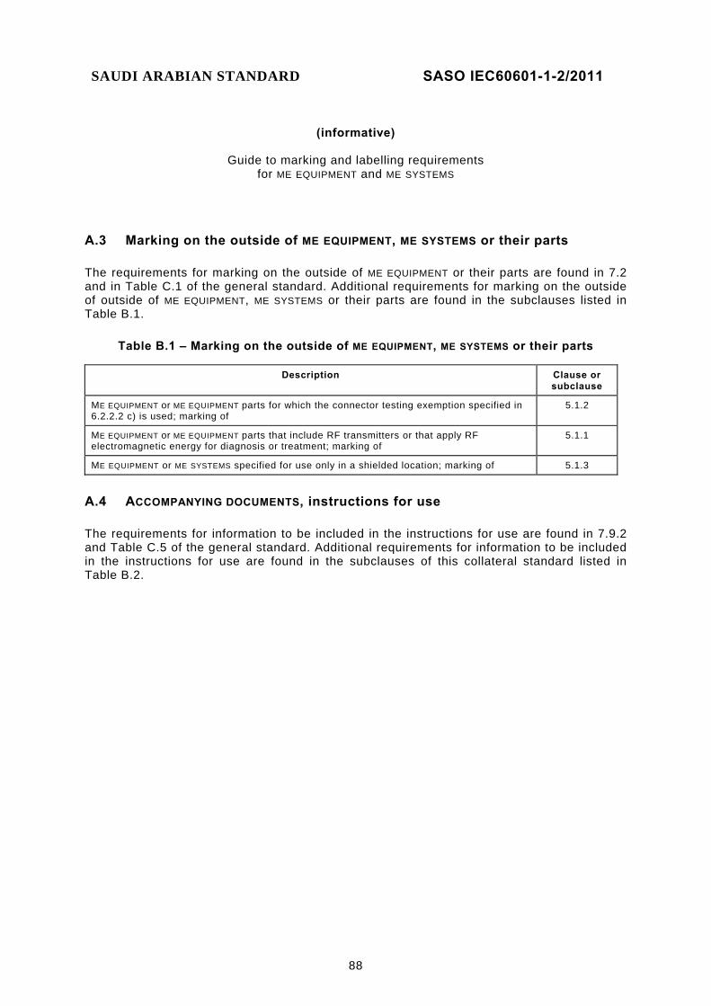
SAUDI ARABIAN STANDARD SASO IEC60601-1-2/2011
88
(informative)
Guide to marking and labelling requirements
for ME EQUIPMENT and ME SYSTEMS
A.3 Marking on the outside of ME EQUIPMENT, ME SYSTEMS or their parts
The requirements for marking on the outside of ME EQUIPMENT or their parts are found in 7.2 and in Table C.1 of the general standard. Additional requirements for marking on the outside of outside of ME EQUIPMENT, ME SYSTEMS or their parts are found in the subclauses listed in Table B.1.
Table B.1 – Marking on the outside of ME EQUIPMENT, ME SYSTEMS or their parts
Description Clause or subclause
ME EQUIPMENT or ME EQUIPMENT parts for which the connector testing exemption specified in 6.2.2.2 c) is used; marking of
5.1.2
ME EQUIPMENT or ME EQUIPMENT parts that include RF transmitters or that apply RF electromagnetic energy for diagnosis or treatment; marking of
5.1.1
ME EQUIPMENT or ME SYSTEMS specified for use only in a shielded location; marking of 5.1.3
A.4 ACCOMPANYING DOCUMENTS, instructions for use
The requirements for information to be included in the instructions for use are found in 7.9.2 and Table C.5 of the general standard. Additional requirements for information to be included in the instructions for use are found in the subclauses of this collateral standard listed in Table B.2.
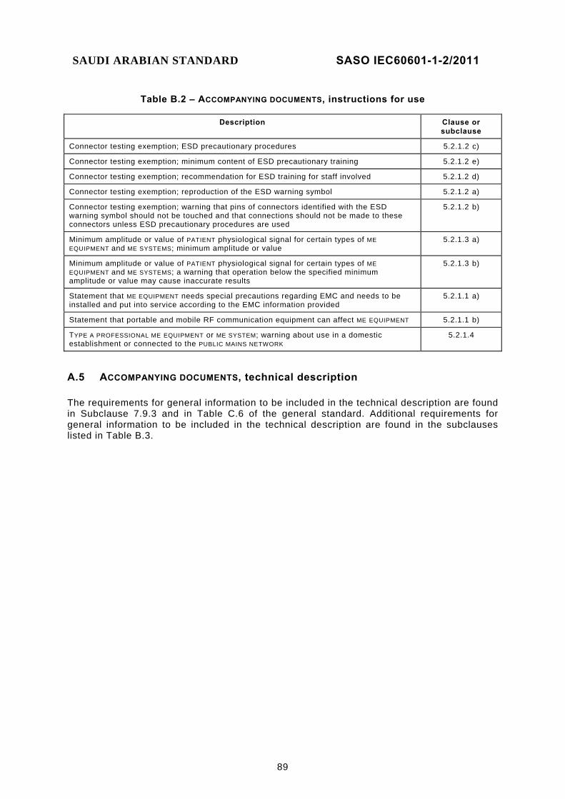
SAUDI ARABIAN STANDARD SASO IEC60601-1-2/2011
89
Table B.2 – ACCOMPANYING DOCUMENTS, instructions for use
Description Clause or subclause
Connector testing exemption; ESD precautionary procedures 5.2.1.2 c)
Connector testing exemption; minimum content of ESD precautionary training 5.2.1.2 e)
Connector testing exemption; recommendation for ESD training for staff involved 5.2.1.2 d)
Connector testing exemption; reproduction of the ESD warning symbol 5.2.1.2 a)
Connector testing exemption; warning that pins of connectors identified with the ESD warning symbol should not be touched and that connections should not be made to these connectors unless ESD precautionary procedures are used
5.2.1.2 b)
Minimum amplitude or value of PATIENT physiological signal for certain types of ME EQUIPMENT and ME SYSTEMS; minimum amplitude or value
5.2.1.3 a)
Minimum amplitude or value of PATIENT physiological signal for certain types of ME EQUIPMENT and ME SYSTEMS; a warning that operation below the specified minimum amplitude or value may cause inaccurate results
5.2.1.3 b)
Statement that ME EQUIPMENT needs special precautions regarding EMC and needs to be installed and put into service according to the EMC information provided
5.2.1.1 a)
Statement that portable and mobile RF communication equipment can affect ME EQUIPMENT 5.2.1.1 b)
TYPE A PROFESSIONAL ME EQUIPMENT or ME SYSTEM; warning about use in a domestic establishment or connected to the PUBLIC MAINS NETWORK
5.2.1.4
A.5 ACCOMPANYING DOCUMENTS, technical description
The requirements for general information to be included in the technical description are found in Subclause 7.9.3 and in Table C.6 of the general standard. Additional requirements for general information to be included in the technical description are found in the subclauses listed in Table B.3.
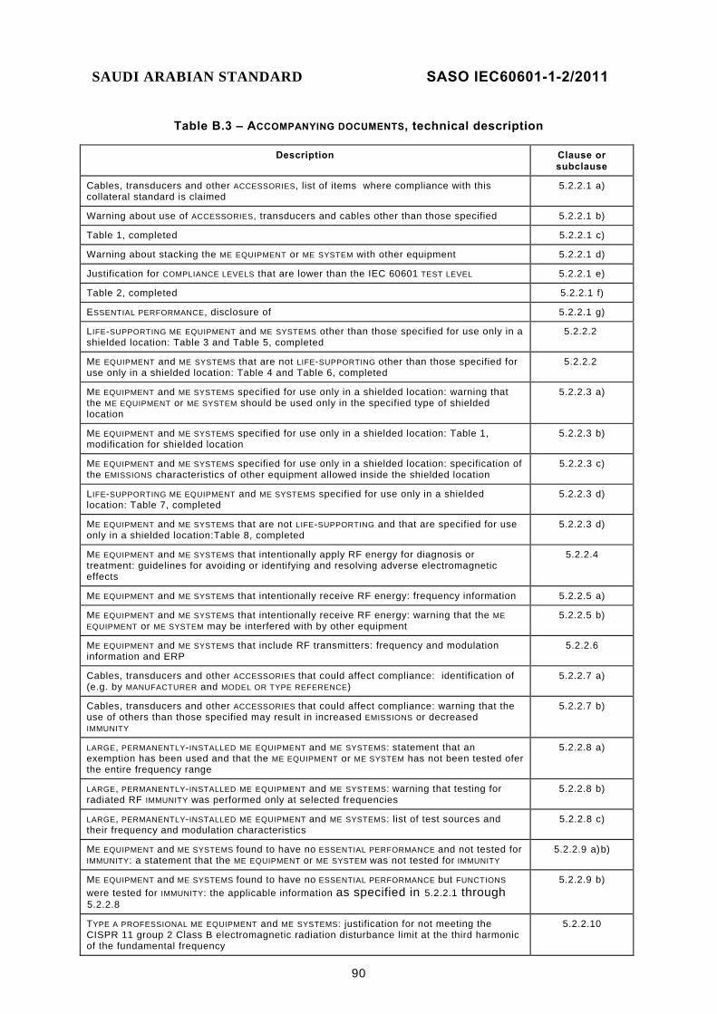
SAUDI ARABIAN STANDARD SASO IEC60601-1-2/2011
90
Table B.3 – ACCOMPANYING DOCUMENTS, technical description
Description Clause or subclause
Cables, transducers and other ACCESSORIES, list of items where compliance with this collateral standard is claimed
5.2.2.1 a)
Warning about use of ACCESSORIES, transducers and cables other than those specified 5.2.2.1 b)
Table 1, completed 5.2.2.1 c)
Warning about stacking the ME EQUIPMENT or ME SYSTEM with other equipment 5.2.2.1 d)
Justification for COMPLIANCE LEVELS that are lower than the IEC 60601 TEST LEVEL 5.2.2.1 e)
Table 2, completed 5.2.2.1 f)
ESSENTIAL PERFORMANCE, disclosure of 5.2.2.1 g)
LIFE-SUPPORTING ME EQUIPMENT and ME SYSTEMS other than those specified for use only in a shielded location: Table 3 and Table 5, completed
5.2.2.2
ME EQUIPMENT and ME SYSTEMS that are not LIFE-SUPPORTING other than those specified for use only in a shielded location: Table 4 and Table 6, completed
5.2.2.2
ME EQUIPMENT and ME SYSTEMS specified for use only in a shielded location: warning that the ME EQUIPMENT or ME SYSTEM should be used only in the specified type of shielded location
5.2.2.3 a)
ME EQUIPMENT and ME SYSTEMS specified for use only in a shielded location: Table 1, modification for shielded location
5.2.2.3 b)
ME EQUIPMENT and ME SYSTEMS specified for use only in a shielded location: specification of the EMISSIONS characteristics of other equipment allowed inside the shielded location
5.2.2.3 c)
LIFE-SUPPORTING ME EQUIPMENT and ME SYSTEMS specified for use only in a shielded location: Table 7, completed
5.2.2.3 d)
ME EQUIPMENT and ME SYSTEMS that are not LIFE-SUPPORTING and that are specified for use only in a shielded location:Table 8, completed
5.2.2.3 d)
ME EQUIPMENT and ME SYSTEMS that intentionally apply RF energy for diagnosis or treatment: guidelines for avoiding or identifying and resolving adverse electromagnetic effects
5.2.2.4
ME EQUIPMENT and ME SYSTEMS that intentionally receive RF energy: frequency information 5.2.2.5 a)
ME EQUIPMENT and ME SYSTEMS that intentionally receive RF energy: warning that the ME EQUIPMENT or ME SYSTEM may be interfered with by other equipment
5.2.2.5 b)
ME EQUIPMENT and ME SYSTEMS that include RF transmitters: frequency and modulation information and ERP
5.2.2.6
Cables, transducers and other ACCESSORIES that could affect compliance: identification of (e.g. by MANUFACTURER and MODEL OR TYPE REFERENCE)
5.2.2.7 a)
Cables, transducers and other ACCESSORIES that could affect compliance: warning that the use of others than those specified may result in increased EMISSIONS or decreased IMMUNITY
5.2.2.7 b)
LARGE, PERMANENTLY-INSTALLED ME EQUIPMENT and ME SYSTEMS: statement that an exemption has been used and that the ME EQUIPMENT or ME SYSTEM has not been tested ofer the entire frequency range
5.2.2.8 a)
LARGE, PERMANENTLY-INSTALLED ME EQUIPMENT and ME SYSTEMS: warning that testing for radiated RF IMMUNITY was performed only at selected frequencies
5.2.2.8 b)
LARGE, PERMANENTLY-INSTALLED ME EQUIPMENT and ME SYSTEMS: list of test sources and their frequency and modulation characteristics
5.2.2.8 c)
ME EQUIPMENT and ME SYSTEMS found to have no ESSENTIAL PERFORMANCE and not tested for IMMUNITY: a statement that the ME EQUIPMENT or ME SYSTEM was not tested for IMMUNITY
5.2.2.9 a) b)
ME EQUIPMENT and ME SYSTEMS found to have no ESSENTIAL PERFORMANCE but FUNCTIONS were tested for IMMUNITY: the applicable information as specified in 5.2.2.1 through 5.2.2.8
5.2.2.9 b)
TYPE A PROFESSIONAL ME EQUIPMENT and ME SYSTEMS: justification for not meeting the CISPR 11 group 2 Class B electromagnetic radiation disturbance limit at the third harmonic of the fundamental frequency
5.2.2.10

SAUDI ARABIAN STANDARD SASO IEC60601-1-2/2011
91
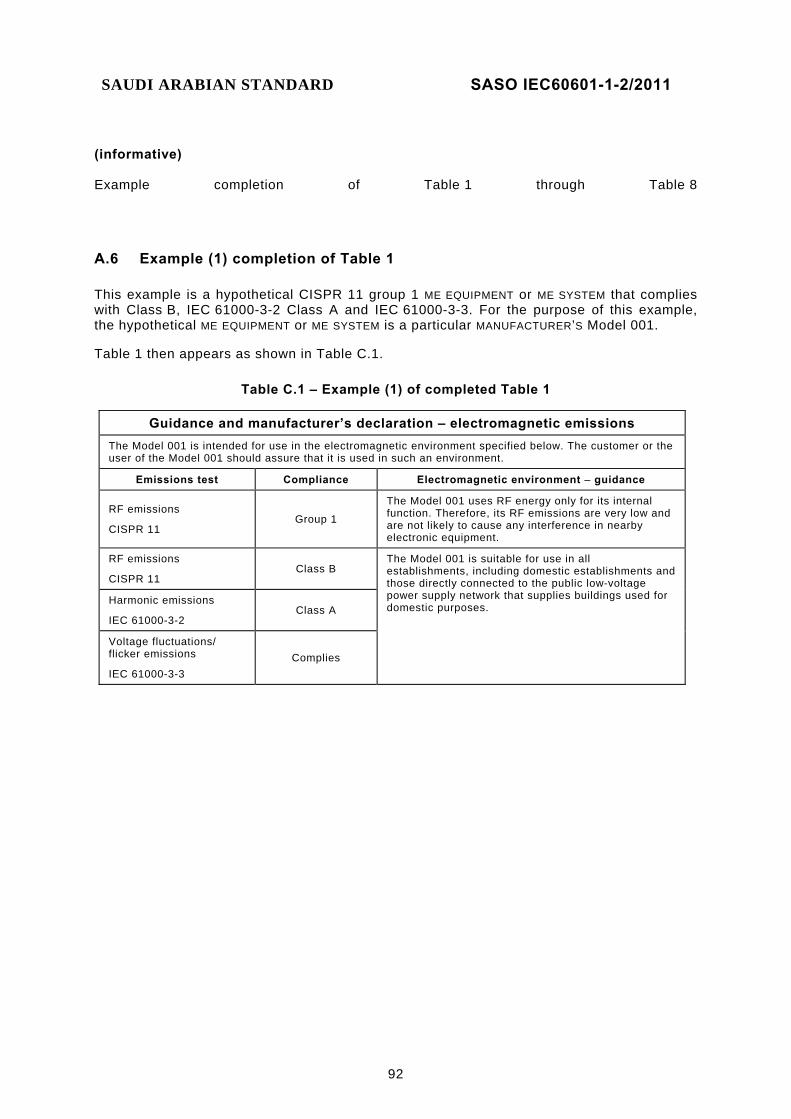
SAUDI ARABIAN STANDARD SASO IEC60601-1-2/2011
92
(informative) Example completion of Table 1 through Table 8
A.6 Example (1) completion of Table 1
This example is a hypothetical CISPR 11 group 1 ME EQUIPMENT or ME SYSTEM that complies with Class B, IEC 61000-3-2 Class A and IEC 61000-3-3. For the purpose of this example, the hypothetical ME EQUIPMENT or ME SYSTEM is a particular MANUFACTURER’S Model 001.
Table 1 then appears as shown in Table C.1.
Table C.1 – Example (1) of completed Table 1
Guidance and manufacturer’s declaration – electromagnetic emissions
The Model 001 is intended for use in the electromagnetic environment specified below. The customer or the user of the Model 001 should assure that it is used in such an environment.
Emissions test Compliance Electromagnetic environment – guidance
RF emissions
CISPR 11 Group 1
The Model 001 uses RF energy only for its internal function. Therefore, its RF emissions are very low and are not likely to cause any interference in nearby electronic equipment.
RF emissions
CISPR 11 Class B
The Model 001 is suitable for use in all establishments, including domestic establishments and those directly connected to the public low-voltage power supply network that supplies buildings used for domestic purposes.
Harmonic emissions
IEC 61000-3-2 Class A
Voltage fluctuations/ flicker emissions
IEC 61000-3-3 Complies

SAUDI ARABIAN STANDARD SASO IEC60601-1-2/2011
93
A.7 Example (2) completion of Table 1
This example is a hypothetical CISPR 11 group 2 ME EQUIPMENT or ME SYSTEM that complies with Class A and for which IEC 61000-3-2 and IEC 61000-3-3 are not applicable. For the purpose of this example, the hypothetical ME EQUIPMENT or ME SYSTEM is a particular MANUFACTURER’S Model 002.
Table 1 then appears as shown in Table C.2.
Table C.2 – Example (2) of completed Table 1
Guidance and manufacturer’s declaration – electromagnetic emissions
The Model 002 is intended for use in the electromagnetic environment specified below. The customer or the user of the Model 002 should assure that it is used in such an environment.
Emissions test Compliance Electromagnetic environment – guidance
RF emissions
CISPR 11
Group 2
The Model 002 must emit electromagnetic energy in order to perform its intended function. Nearby electronic equipment may be affected.
RF emissions
CISPR 11 Class A
The Model 002 is suitable for use in all establishments other than domestic and those directly connected to the public low-voltage power supply network that supplies buildings used for domestic purposes. Harmonic emissions
IEC 61000-3-2 Not applicable
Voltage fluctuations/ flicker emissions
IEC 61000-3-3 Not applicable

SAUDI ARABIAN STANDARD SASO IEC60601-1-2/2011
94
A.8 Example (3) completion of Table 1
This example is a hypothetical magnetic resonance imaging (MRI) ME SYSTEM that is specified for use only in a shielded location, complies with CISPR 11 Class A when installed in the specified type of shielded location, and for which IEC 61000-3-2 and IEC 61000-3-3 are not applicable. For the purpose of this example, the hypothetical MRI ME SYSTEM is a particular MANUFACTURER’S Model 003. (See also Clause C.8.)
Table 1 then appears as shown in Table C.3.
Table C.3 – Example (3) of completed Table 1
Guidance and manufacturer’s declaration – electromagnetic emissions
The Model 003 MRI system is intended for use in the electromagnetic environment specified below. The customer or the user of the Model 003 should assure that it is used in such an environment.
Emissions test Compliance Electromagnetic environment – guidance
RF emissions
CISPR 11
Group 2
The Model 003 MRI system must emit electromagnetic energy in order to perform its intended function. Nearby electronic equipment may be affected.
RF emissions
CISPR 11
Class A (the Model 003 MRI system in combination
with the shielded location)
The Model 003 MRI system must be used only in a shielded location with a minimum RF shielding effectiveness and, for each cable that exits the shielded location, a minimum RF filter attenuation of 80 dB from 10 MHz to 20 MHz, 100 dB from 20 MHz to 80 MHz and 80 dB from 80 MHz to 100 MHz. (The minimum at 20 MHz is 100 dB and the minimum at 80 MHz is 80 dB.)
The Model 003 MRI system, when installed in such a shielded location, is suitable for use in all establishments other than domestic and those directly connected to the public low-voltage power supply network that supplies buildings used for domestic purposes.
Harmonic emissions
IEC 61000-3-2 Not applicable
Voltage fluctuations/ flicker emissions
IEC 61000-3-3 Not applicable
NOTE It is essential that the actual shielding effectiveness and filter attenuation of the shielded location be verified to assure that they meet the minimum specifications.

SAUDI ARABIAN STANDARD SASO IEC60601-1-2/2011
95
A.9 Example completion of Table 2
This example is a hypothetical image intensifier that complies with all IEC 60601 TEST LEVELS of this collateral standard except for the power frequency magnetic field IMMUNITY requirement. The power frequency magnetic field IMMUNITY of the example image intensifier is 0,3 A/m. For the purpose of this example, the hypothetical image intensifier is a particular MANUFACTURER’S Model 004.
Table 2 then appears as shown in Table C.4.
Table C.4 – Example of completed Table 2
Guidance and manufacturer’s declaration – electromagnetic immunity The Model 004 Image Intensifier is intended for use in the electromagnetic environment specified below. The customer or the user of the Model 004 Image Intensifier should assure that it is used in such an environment.
IMMUNITY test IEC 60601 test level Compliance level Electromagnetic environment –
guidance
Electrostatic discharge (ESD)
IEC 61000-4-2
± 6 kV contact
± 8 kV air
± 6 kV contact
± 8 kV air
Floors should be wood, concrete or ceramic tile. If floors are covered with synthetic material, the relative humidity should be at least 30 %.
Electrical fast transient/burst
IEC 61000-4-4
± 2 kV for power supply lines
± 1 kV for input/output lines
± 2 kV for power supply lines
± 1 kV for input/output lines
Mains power quality should be that of a typical commercial or hospital environment.
Surge
IEC 61000-4-5
± 1 kV line(s) to line(s)
± 2 kV line(s) to earth
± 1 kV differential mode
± 2 kV common mode
Mains power quality should be that of a typical commercial or hospital environment.
Voltage dips, short interruptions and voltage variations on power supply input lines
IEC 61000-4-11
<5 % UT (>95 % dip in UT) for 0,5 cycle
40 % UT (60 % dip in UT) for 5 cycles
70 % UT (30 % dip in UT) for 25 cycles
<5 % UT (>95 % dip in UT) for 5 s
<5 % UT (>95 % dip in UT) for 0,5 cycle
40 % UT (60 % dip in UT) for 5 cycles
70 % UT (30 % dip in UT) for 25 cycles
<5 % UT (>95 % dip in UT) for 5 s
Mains power quality should be that of a typical commercial or hospital environment. If the user of the Model 004 image intensifier requires continued operation during power mains interruptions, it is recommended that the Model 004 Image Intensifier be powered from an uninterruptible power supply or a battery.
Power frequency (50/60 Hz) magnetic field
IEC 61000-4-8
3 A/m 0,3 A/m If image distortion occurs, it may be necessary to position the Model 004 image intensifier further from sources of power frequency magnetic fields or to install magnetic shielding. The power frequency magnetic field should be measured in the intended installation location to assure that it is sufficiently low.
NOTE UT is the a.c. mains voltage prior to application of the test level.
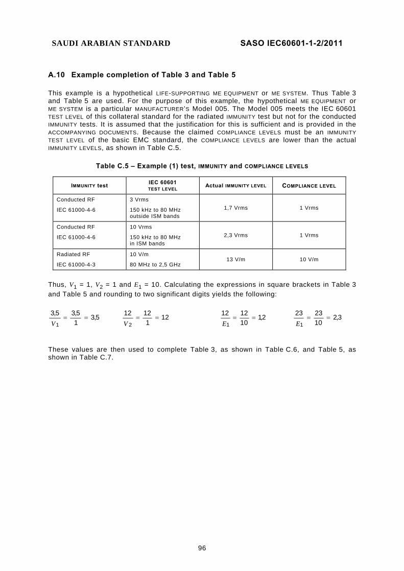
SAUDI ARABIAN STANDARD SASO IEC60601-1-2/2011
96
A.10 Example completion of Table 3 and Table 5
This example is a hypothetical LIFE-SUPPORTING ME EQUIPMENT or ME SYSTEM. Thus Table 3 and Table 5 are used. For the purpose of this example, the hypothetical ME EQUIPMENT or ME SYSTEM is a particular MANUFACTURER’S Model 005. The Model 005 meets the IEC 60601 TEST LEVEL of this collateral standard for the radiated IMMUNITY test but not for the conducted IMMUNITY tests. It is assumed that the justification for this is sufficient and is provided in the ACCOMPANYING DOCUMENTS. Because the claimed COMPLIANCE LEVELS must be an IMMUNITY TEST LEVEL of the basic EMC standard, the COMPLIANCE LEVELS are lower than the actual IMMUNITY LEVELS, as shown in Table C.5.
Table C.5 – Example (1) test, IMMUNITY and COMPLIANCE LEVELS
IMMUNITY test IEC 60601 TEST LEVEL Actual IMMUNITY LEVEL COMPLIANCE LEVEL
Conducted RF
IEC 61000-4-6
3 Vrms
150 kHz to 80 MHz outside ISM bands
1,7 Vrms 1 Vrms
Conducted RF
IEC 61000-4-6
10 Vrms
150 kHz to 80 MHz in ISM bands
2,3 Vrms 1 Vrms
Radiated RF
IEC 61000-4-3
10 V/m
80 MHz to 2,5 GHz 13 V/m 10 V/m
Thus, V1 = 1, V2 = 1 and E1 = 10. Calculating the expressions in square brackets in Table 3 and Table 5 and rounding to two significant digits yields the following:
5,315,35,3
1==
V 12
11212
2==
V 2,1
101212
1==
E 3,2
102323
1==
E
These values are then used to complete Table 3, as shown in Table C.6, and Table 5, as shown in Table C.7.

SAUDI ARABIAN STANDARD SASO IEC60601-1-2/2011
97
Table C.6 – Example of completed Table 3
Guidance and manufacturer’s declaration – electromagnetic immunity
The Model 005 is intended for use in the electromagnetic environment specified below. The customer or the user of the Model 005 should assure that it is used in such an electromagnetic environment.
IMMUNITY test IEC 60601 TEST LEVEL
Compliance level Electromagnetic environment – guidance
Conducted RF
IEC 61000-4-6
Radiated RF
IEC 61000-4-3
3 Vrms
150 kHz to 80 MHz outside ISM bandsa
10 Vrms
150 kHz to 80 MHz in ISM bandsa 10 V/m
80 MHz to 2,5 GHz
1 Vrms
1 Vrms
10 V/m
Portable and mobile RF communications equipment should be used no closer to any part of the Model 005, including cables, than the recommended separation distance calculated from the equation applicable to the frequency of the transmitter.
Recommended separation distance
P=d 5,3
Pd 12=
P=d 2,1 80 MHz to 800 MHz
P=d 3,2 800 MHz to 2,5 GHz
where P is the maximum output power rating of the transmitter in watts (W) according to the transmitter manufacturer and d is the recommended separation distance in metres (m).b
Field strengths from fixed RF transmitters, as determined by an electromagnetic site survey,c should be less than the compliance level in each frequency range.d
Interference may occur in the vicinity of equipment marked with the following symbol:
NOTE 1 At 80 MHz and 800 MHz, the higher frequency range applies.
NOTE 2 These guidelines may not apply in all situations. Electromagnetic propagation is affected by absorption and reflection from structures, objects and people.
a The ISM (industrial, scientific and medical) bands between 150 kHz and 80 MHz are 6,765 MHz to 6,795 MHz; 13,553 MHz to 13,567 MHz; 26,957 MHz to 27,283 MHz; and 40,66 MHz to 40,70 MHz.
b The compliance levels in the ISM frequency bands between 150 kHz and 80 MHz and in the frequency range 80 MHz to 2,5 GHz are intended to decrease the likelihood that mobile/portable communications equipment could cause interference if it is inadvertently brought into patient areas. For this reason, an additional factor of 10/3 has been incorporated into the formulae used in calculating the recommended separation distance for transmitters in these frequency ranges.
c Field strengths from fixed transmitters, such as base stations for radio (cellular/cordless) telephones and land mobile radios, amateur radio, AM and FM radio broadcast and TV broadcast cannot be predicted theoretically with accuracy. To assess the electromagnetic environment due to fixed RF transmitters, an electromagnetic site survey should be considered. If the measured field strength in the location in which the Model 005 is used exceeds the applicable RF compliance level above, the Model 005 should be observed to verify normal operation. If abnormal performance is observed, additional measures may be necessary, such as re-orienting or relocating the Model 005.
d Over the frequency range 150 kHz to 80 MHz, field strengths should be less than 1 V/m.

SAUDI ARABIAN STANDARD SASO IEC60601-1-2/2011
98
Table C.7 – Example of completed Table 5
Recommended separation distances between portable and mobile RF communications equipment and the Model 005
The Model 005 is intended for use in an electromagnetic environment in which radiated RF disturbances are controlled. The customer or the user of the Model 005 can help prevent electromagnetic interference by maintaining a minimum distance between portable and mobile RF communications equipment (transmitters) and the Model 005 as recommended below, according to the maximum output power of the communications equipment.
Rated maximum output power of transmitter
W
Separation distance according to frequency of transmitter m
150 kHz to 80 MHzoutside ISM
bands
P=d 5,3
150 kHz to 80 MHzin ISM bands
Pd 12=
80 MHz to 800 MHz
Pd 2,1=
800 MHz to 2,5 GHz
P=d 3,2
0,01 0,35 1,2 0,12 0,23
0,1 1,1 3,8 0,38 0,73
1 3,5 12 1,2 2,3
10 11 38 3,8 7,3
100 35 120 12 23
For transmitters rated at a maximum output power not listed above, the recommended separation distance d in metres (m) can be determined using the equation applicable to the frequency of the transmitter, where P is the maximum output power rating of the transmitter in watts (W) according to the transmitter manufacturer. NOTE 1 At 80 MHz and 800 MHz, the separation distance for the higher frequency range applies.
NOTE 2 The ISM (industrial, scientific and medical) bands between 150 kHz and 80 MHz are 6,765 MHz to 6,795 MHz; 13,553 MHz to 13,567 MHz; 26,957 MHz to 27,283 MHz; and 40,66 MHz to 40,70 MHz.
NOTE 3 An additional factor of 10/3 has been incorporated into the formulae used in calculating the recommended separation distance for transmitters in the ISM frequency bands between 150 kHz and 80 MHz and in the frequency range 80 MHz to 2,5 GHz to decrease the likelihood that mobile/portable communications equipment could cause interference if it is inadvertently brought into patient areas.
NOTE 4 These guidelines may not apply in all situations. Electromagnetic propagation is affected by absorption and reflection from structures, objects and people.
A.11 Example completion of Table 4 and Table 6
This example is a hypothetical ME EQUIPMENT or ME SYSTEM that is not LIFE-SUPPORTING and that meets the IEC 60601 TEST LEVELS of this collateral standard for the radiated and conducted IMMUNITY tests. Thus, Table 4 and Table 6 are used. For the purpose of this example, the hypothetical ME EQUIPMENT or ME SYSTEM is a particular MANUFACTURER’S Model 006.
Using the IEC 60601 TEST LEVELS, V1 = 3 and E1 = 3. Calculating the expressions in square brackets in Table 4 and Table 6 and rounding to two significant digits yields the following:
2,135,35,3
1≈=
V 2,1
35,35,3
1≈=
E 3,2
377
1≈=
E
These values are then used to complete Table 4, as shown in Table C.8, and Table 6, as shown in Table C.9.

SAUDI ARABIAN STANDARD SASO IEC60601-1-2/2011
99
Table C.8 – Example of completed Table 4
Guidance and manufacturer’s declaration – electromagnetic immunity
The Model 006 is intended for use in the electromagnetic environment specified below. The customer or the user of the Model 006 should assure that it is used in such an environment.
IMMUNITY test IEC 60601 TEST LEVEL
Compliance level Electromagnetic environment – guidance
Conducted RF
IEC 61000-4-6
Radiated RF
IEC 61000-4-3
3 Vrms
150 kHz to 80 MHz
3 V/m
80 MHz to 2,5 GHz
3 Vrms
3 V/m
Portable and mobile RF communications equipment should be used no closer to any part of the Model 006, including cables, than the recommended separation distance calculated from the equation applicable to the frequency of the transmitter.
Recommended separation distance
P=d 2,1
P=d 2,1 80 MHz to 800 MHz
P=d 3,2 800 MHz to 2,5 GHz
where P is the maximum output power rating of the transmitter in watts (W) according to the transmitter manufacturer and d is the recommended separation distance in metres (m).
Field strengths from fixed RF transmitters, as deter-mined by an electromagnetic site survey,a should be less than the compliance level in each frequency range.b
Interference may occur in the vicinity of equipment marked with the following symbol:
NOTE 1 At 80 MHz and 800 MHz, the higher frequency range applies.
NOTE 2 These guidelines may not apply in all situations. Electromagnetic propagation is affected by absorption and reflection from structures, objects and people.
a Field strengths from fixed transmitters, such as base stations for radio (cellular/cordless) telephones and land mobile radios, amateur radio, AM and FM radio broadcast and TV broadcast cannot be predicted theoretically with accuracy. To assess the electromagnetic environment due to fixed RF transmitters, an electromagnetic site survey should be considered. If the measured field strength in the location in which the Model 006 is used exceeds the applicable RF compliance level above, the Model 006 should be observed to verify normal operation. If abnormal performance is observed, additional measures may be necessary, such as re-orienting or relocating the Model 006.
b Over the frequency range 150 kHz to 80 MHz, field strengths should be less than 3 V/m.

SAUDI ARABIAN STANDARD SASO IEC60601-1-2/2011
100
Table C.9 – Example of completed Table 6
Recommended separation distances between portable and mobile RF communications equipment and the Model 006
The Model 006 is intended for use in an electromagnetic environment in which radiated RF disturbances are controlled. The customer or the user of the Model 006 can help prevent electromagnetic interference by maintaining a minimum distance between portable and mobile RF communications equipment (transmitters) and the Model 006 as recommended below, according to the maximum output power of the communications equipment.
Rated maximum output power of transmitter
W
Separation distance according to frequency of transmitter m
150 kHz to 80 MHz
P=d 2,1
80 MHz to 800 MHz
P=d 2,1
800 MHz to 2,5 GHz
P=d 3,2
0,01 0,12 0,12 0,23
0,1 0,38 0,38 0,73
1 1,2 1,2 2,3
10 3,8 3,8 7,3
100 12 12 23
For transmitters rated at a maximum output power not listed above, the recommended separation distance d in metres (m) can be estimated using the equation applicable to the frequency of the transmitter, where P is the maximum output power rating of the transmitter in watts (W) according to the transmitter manufacturer. NOTE 1 At 80 MHz and 800 MHz, the separation distance for the higher frequency range applies.
NOTE 2 These guidelines may not apply in all situations. Electromagnetic propagation is affected by absorption and reflection from structures, objects and people.
A.12 Example completion of Table 7
This example is a hypothetical ME EQUIPMENT or ME SYSTEM that is LIFE-SUPPORTING and that is specified for use only in a shielded location with a minimum RF shielding effectiveness and filter attenuation of 31 dB over the frequency range 150 kHz to 2,5 GHz. Thus, Table 7 is used. For the purpose of this example, the hypothetical ME EQUIPMENT or ME SYSTEM is a particular MANUFACTURER’S Model 007, and the required list of equipment that is allowed or prohibited inside the shielded location with the Model 007 is found on page 48 of the service manual.
The actual IMMUNITY LEVELS are below the lowest level listed in the basic EMC IMMUNITY standard; therefore, the COMPLIANCE LEVELS are equal to the actual IMMUNITY LEVELS, as shown in Table C.10. These values are then used to complete Table 7, as shown in Table C.11.
Table C.10 – Example (2) test, IMMUNITY and COMPLIANCE LEVELS
IMMUNITY test IEC 60601 TEST LEVEL Actual IMMUNITY LEVEL COMPLIANCE LEVEL
Conducted RF
IEC 61000-4-6
3 Vrms
150 kHz to 80 MHz outside ISM bands
0,3 Vrms 0,3 Vrms
Conducted RF
IEC 61000-4-6
10 Vrms
150 kHz to 80 MHz in ISM bands
0,3 Vrms 0,3 Vrms
Radiated RF
IEC 61000-4-3
10 V/m
800 MHz to 2,5 GHz 0,3 V/m 0,3 V/m

SAUDI ARABIAN STANDARD SASO IEC60601-1-2/2011
101

SAUDI ARABIAN STANDARD SASO IEC60601-1-2/2011
102
Table C.11 – Example of completed Table 7
Guidance and manufacturer’s declaration – electromagnetic immunity The Model 007 is suitable for use in the electromagnetic environment specified below. The customer or the user of the Model 007 should assure that it is used in such an electromagnetic environment.
IMMUNITY test IEC 60601 TEST LEVEL
Compliance level Electromagnetic environment – guidance
Conducted RF
IEC 61000-4-6
Radiated RF
IEC 61000-4-3
3 Vrms
150 kHz to 80 MHz outside ISM bandsa
10 Vrms
150 kHz to 80 MHz in ISM bandsa
10 V/m
80 MHz to 2,5 GHz
0,3 Vrms
0,3 Vrms
0,3 V/m
The Model 007 must be used only in a shielded location with a minimum RF shielding effectiveness and, for each cable that enters the shielded location, a minimum RF filter attenuation of 31 dB over the frequency range 150 kHz to 2,5 GHz. See page 48 of the Service Manual.
Field strengths outside the shielded location from fixed RF transmitters, as determined by an electro-magnetic site survey, should be less than 10 V/m.b
Interference may occur in the vicinity of equipment marked with the following symbol:
NOTE 1 These guidelines may not apply in all situations. Electromagnetic propagation is affected by absorption and reflection from structures, objects and people.
NOTE 2 It is essential that the actual shielding effectiveness and filter attenuation of the shielded location be verified to assure that they meet the minimum specification.
a The ISM (industrial, scientific and medical) bands between 150 kHz and 80 MHz are 6,765 MHz to 6,795 MHz; 13,553 MHz to 13,567 MHz; 26,957 MHz to 27,283 MHz; and 40,66 MHz to 40,70 MHz.
b Field strengths from fixed transmitters, such as base stations for radio (cellular/cordless) telephones and land mobile radios, amateur radio, AM and FM radio broadcast and TV broadcast cannot be predicted theoretically with accuracy. To assess the electromagnetic environment due to fixed RF transmitters, an electromagnetic site survey should be considered. If the measured field strength outside the shielded location in which the Model 007 is used exceeds 10 V/m, observe the Model 007 to verify normal operation. If abnormal performance is observed, additional measures may be necessary, such as relocating the model 007 or using a shielded location with a higher RF shielding effectiveness and filter attenuation.
A.13 Example completion of Table 8
This example is a hypothetical magnetic resonance imaging (MRI) ME SYSTEM that is specified for use only in a shielded location with a minimum RF shielding effectiveness and filter attenuation of 80 dB over the frequency range 10 MHz to 20 MHz, 100 dB over the frequency range 20 MHz to 80 MHz and 80 dB over the frequency range 80 MHz to 100 MHz. (At 20 MHz and 80 MHz, the higher frequency range applies.) Thus, Table 8 is used. For the purpose of this example, the hypothetical MRI ME SYSTEM is a particular MANUFACTURER’S Model 003, and the required list of equipment that is allowed or prohibited inside the shielded location with the Model 003 is found on page 25 of the service manual. (See also Clause A.8.)
Some of the actual IMMUNITY LEVELS are below the lowest level listed in the basic EMC IMMUNITY standard; therefore, those COMPLIANCE LEVELS are equal to the actual IMMUNITY LEVELS, as shown in Table C.12. These values are then used to complete Table 8, as shown in Table C.13.
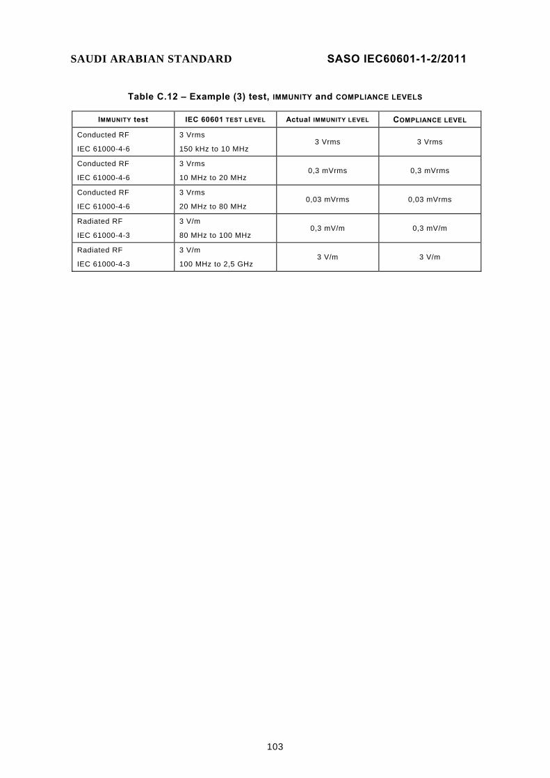
SAUDI ARABIAN STANDARD SASO IEC60601-1-2/2011
103
Table C.12 – Example (3) test, IMMUNITY and COMPLIANCE LEVELS
IMMUNITY test IEC 60601 TEST LEVEL Actual IMMUNITY LEVEL COMPLIANCE LEVEL
Conducted RF
IEC 61000-4-6
3 Vrms
150 kHz to 10 MHz 3 Vrms 3 Vrms
Conducted RF
IEC 61000-4-6
3 Vrms
10 MHz to 20 MHz 0,3 mVrms 0,3 mVrms
Conducted RF
IEC 61000-4-6
3 Vrms
20 MHz to 80 MHz 0,03 mVrms 0,03 mVrms
Radiated RF
IEC 61000-4-3
3 V/m
80 MHz to 100 MHz 0,3 mV/m 0,3 mV/m
Radiated RF
IEC 61000-4-3
3 V/m
100 MHz to 2,5 GHz 3 V/m 3 V/m

SAUDI ARABIAN STANDARD SASO IEC60601-1-2/2011
104
Table C.13 – Example of completed Table 8
Guidance and manufacturer’s declaration – electromagnetic immunity The Model 003 MRI system is intended for use in the electromagnetic environment specified below. The customer or the user of the Model 003 MRI system should assure that it is used in such an electromagnetic environment.
IMMUNITY test IEC 60601 TEST LEVEL
Compliance level Electromagnetic environment – guidance
Conducted RF
IEC 61000-4-6
Radiated RF
IEC 61000-4-3
3 Vrms
150 kHz to 80 MHz
3 V/m
80 MHz to 2,5 GHz
3 Vrms
150 kHz to 10 MHz
0,3 mVrms
10 MHz to 20 MHz
0,03 mVrms
20 MHz to 80 MHz
0,3 mV/m
80 MHz to 100 MHz
3 V/m
100 MHz to 2,5 GHz
The Model 003 MRI system must be used only in a shielded location with a minimum RF shielding effectiveness and, for each cable that enters the shielded location, a minimum RF filter attenuation of 80 dB from 10 MHz to 20 MHz, 100 dB from 20 MHz to 80 MHz and 80 dB from 80 MHz to 100 MHz. (The minimum at 20 MHz is 100 dB and the minimum at 80 MHz is 80 dB.) See page 25 of the Service manual.
Field strengths outside the shielded location from fixed RF transmitters, as determined by an electromagnetic site survey, should be less than 3 V/m.a
Interference may occur in the vicinity of equipment marked with the following symbol:
NOTE 1 These guidelines may not apply in all situations. Electromagnetic propagation is affected by absorption and reflection from structures, objects and people.
NOTE 2 It is essential that the actual shielding effectiveness and filter attenuation of the shielded location be verified to assure that they meet the minimum specification.
a Field strengths from fixed transmitters, such as base stations for radio (cellular/cordless) telephones and land mobile radios, amateur radio, AM and FM radio broadcast and TV broadcast cannot be predicted theoretically with accuracy. To assess the electromagnetic environment due to fixed RF transmitters, an electromagnetic site survey should be considered. If the measured field strength outside the shielded location in which the Model 003 MRI system is used exceeds 3 V/m, the Model 003 MRI system should be observed to verify normal operation. If abnormal performance is observed, additional measures may be necessary, such as relocating the Model 003 MRI system or using a shielded location with a higher RF shielding effectiveness and filter attenuation.

SAUDI ARABIAN STANDARD SASO IEC60601-1-2/2011
105
(informative) Guidance in classification according to CISPR 11
A.14 General
Rules for classification and separation into groups of equipment are specified in CISPR 11. The purpose of this annex is to provide additional guidance in the assignment of ME EQUIPMENT or an ME SYSTEM to the appropriate CISPR 11 group and class.
According to CISPR 11:2003 [1] (Subclause 4.1: Separation into groups):
– Group 1 contains all ISM equipment in which there is intentionally generated or used conductively coupled RF energy that is necessary for the internal functioning of the equipment itself.
– Group 2 contains all ISM equipment in which RF energy is intentionally generated or used in the form of electromagnetic radiation for the treatment of material, and electro-discharge machining and arc welding equipment.
– spark erosion equipment.
According to CISPR 11:2003 [1] (Subclause 4.2: Division into classes):
– Class A equipment is equipment suitable for use in all establishments other than domestic and those directly connected to the public low-voltage power supply network that supplies buildings used for domestic purposes. NOTE Although class A limits have been derived for industrial and commercial establishments, administrations may allow, with whatever additional measures are necessary, the installation and use of Class A ISM equipment in a domestic establishment or in an establishment connected directly to domestic electricity power supplies. 11)
– Class B equipment is equipment suitable for use in all establishments, including domestic establishments and those directly connected to the public low-voltage power supply network that supplies buildings used for domestic purposes.
Annex A of CISPR 11:2003 [1] gives examples of equipment classification. "Medical equipment" is listed as an example of group 1 equipment, whereas "medical apparatus" is listed as an example of group 2 equipment. Only short wave and microwave therapy equipment is mentioned explicitly. No other type of ME EQUIPMENT or ME SYSTEM is mentioned.
A.15 Separation into groups
Most types of ME EQUIPMENT and ME SYSTEMS generate or use RF energy only for their internal functioning and therefore belong to group 1.
Examples of group 1 ME EQUIPMENT and ME SYSTEMS are as follows:
− Electro- and magneto-cardiography ME EQUIPMENT and ME SYSTEMS;
− Electro- and magneto-encephalography ME EQUIPMENT and ME SYSTEMS;
− Electro- and magneto-myography ME EQUIPMENT and ME SYSTEMS.
__________ 11) Note 2 from Subclause 4.2 of CISPR 11:2003 [1].

SAUDI ARABIAN STANDARD SASO IEC60601-1-2/2011
106
Group 1 also includes ME EQUIPMENT and ME SYSTEMS intended to deliver energy to the PATIENT, but in a form that is other than RF electromagnetic. Examples are as follows:
– Medical imaging ME EQUIPMENT and ME SYSTEMS: – diagnostic X-ray systems for radiography and fluoroscopy (including
cinefluoroscopy) for general purpose but also for special purposes, e.g. angiography, mammography, therapy planning, dentistry;
– computed tomography ME SYSTEMS; – ME SYSTEMS for nuclear medicine; – diagnostic ultrasound ME EQUIPMENT.
– Therapy ME EQUIPMENT and ME SYSTEMS: – therapeutic X-ray ME SYSTEMS; – dental ME EQUIPMENT; – electron beam accelerators; – ultrasound ME EQUIPMENT for therapy; – ME EQUIPMENT for extracorporeal lithotripsy; – infusion pumps; – radiant warmers; – infant incubators; – ventilators.
– Monitoring ME EQUIPMENT and ME SYSTEMS: – impedance plethysmography monitors; – pulse oximeters.
Only a few ME EQUIPMENT and ME SYSTEMS apply RF energy to material (in this case to PATIENTS) and are therefore members of group 2.
Examples are as follows: – Medical imaging ME EQUIPMENT:
– ME SYSTEMS for magnetic resonance imaging. – Therapy ME EQUIPMENT:
– diathermy ME EQUIPMENT (short wave, ultra-short wave, microwave therapy ME EQUIPMENT);
– hyperthermy ME EQUIPMENT.
Additionally, high frequency surgical ME EQUIPMENT and ME SYSTEMS, when active, should be classified as group 2 equipment (similar to spark erosion equipment), because they apply RF energy to the PATIENT.

SAUDI ARABIAN STANDARD SASO IEC60601-1-2/2011
107
A.16 Division into classes
ME EQUIPMENT and ME SYSTEMS predominantly intended for use in domestic establishments and connected to the PUBLIC MAINS NETWORK (e.g. home care ME EQUIPMENT and ME EQUIPMENT for doctors’ offices in residential areas) should meet the requirements for CISPR 11 Class B. However, for some CISPR 11 group 2 ME EQUIPMENT and ME SYSTEMS that are intended for use in domestic establishments or for connection to the PUBLIC MAINS NETWORK, it is not possible to comply with the CISPR 11 group 2 Class B electromagnetic radiation disturbance limit at the third harmonic of the fundamental frequency of the ME EQUIPMENT or ME SYSTEM due to significant physical, technological or physiological limitations. These ME EQUIPMENT and ME SYSTEMS may comply with the CISPR 11 group 2 Class A electromagnetic radiation disturbance limit at the third harmonic of the fundamental frequency of the ME EQUIPMENT or ME SYSTEM, provided they are PROFESSIONAL ME EQUIPMENT and ME SYSTEMS; justification is included in the ACCOMPANYING DOCUMENTS as specified in 5.2.2.10 and a warning is included in the instructions for use as specified in 5.2.1.4 and in the ACCOMPANYING DOCUMENTS as specified in 5.2.2.1 c).
ME EQUIPMENT and ME SYSTEMS that are intended to be connected (e.g. in hospitals) to dedicated supply systems (normally fed by separation transformers) should meet the requirements for either CISPR 11 Class A or Class B.
ME EQUIPMENT and ME SYSTEMS that are specified for use only in a shielded location may be classified based on compliance of the system formed by the ME EQUIPMENT or ME SYSTEM together with the specified type of shielded location, i.e. with the assumption that the ME EQUIPMENT or ME SYSTEM has been installed in a shielded location meeting the ME EQUIPMENT or ME SYSTEM MANUFACTURER’S specifications for minimum RF shielding effectiveness and minimum RF filter attenuation. If classification is made on this basis, Subclause 5.2.2.3 b) requires a statement of this fact to appear in Table 1, as well as a recommendation to verify the actual shielding effectiveness and filter attenuation of the shielded location.

SAUDI ARABIAN STANDARD SASO IEC60601-1-2/2011
108
(informative) Guidance in the application of IEC 60601-1-2 to particular standards
A.17 General
This annex contains recommendations to standards committees and working groups writing EMC requirements for particular standards (IEC 60601-2-X (“Part two”) standards and ISO standards based on IEC 60601-1) to help ensure consistency in the application of IEC 60601-1-2. Such committees are encouraged to contact subcommittee 62A with questions that arise in doing so.
This annex identifies the provisions of IEC 60601-1-2 that should be modified when this collateral standard is applied to particular standards and provides guidance in doing so. It also identifies the provisions that should not be modified. In addition to this annex, the rationales in 0 should be consulted for additional information and guidance in the application of this collateral standard.
A.18 Recommended modifications
Writers of particular standards are encouraged to make modifications or add additional information or clarification as follows.
a) Delete the last sentence of 6.2.1.1. If the particular ME EQUIPMENT or ME SYSTEM cannot meet the IMMUNITY TEST LEVELS specified in 6.2, the particular standard should specify the minimum COMPLIANCE LEVEL allowed for each test and provide justification based upon physical, technological or physiological limitations. Once a lower IMMUNITY TEST LEVEL has been set and justified in a particular standard, the allowance for even lower COMPLIANCE LEVELS (the last sentence of 6.2.1.1) should then be explicitly disallowed by the particular standard.
b) Make modifications to 6.2.1.3, 6.2.1.6, 6.2.1.7 and 6.2.1.8 to be more specific for the particular ME EQUIPMENT or ME SYSTEM, while maintaining the intent of this collateral standard.
c) Make modifications to or supplement 6.2.1.10 to provide specific performance criteria for the particular ME EQUIPMENT or ME SYSTEM that follow the intent of that subclause.
d) If selection of one or two of the following four possibilities for the applicability of Table 1 through Table 8 can be made for a particular standard, this may be specified in 5.2.2:
− Table 3 and Table 5 apply (i.e. the particular ME EQUIPMENT or ME SYSTEM is LIFE-SUPPORTING and not specified for use only in a shielded location);
− Table 4 and Table 6 apply (i.e. the particular ME EQUIPMENT or ME SYSTEM is not LIFE-SUPPORTING and not specified for use only in a shielded location);
− Table 7 applies (i.e. the particular ME EQUIPMENT or ME SYSTEM is LIFE-SUPPORTING and is specified for use only in a shielded location);
− Table 8 applies (i.e. the particular ME EQUIPMENT or ME SYSTEM is not LIFE-SUPPORTING and is specified for use only in a shielded location).

SAUDI ARABIAN STANDARD SASO IEC60601-1-2/2011
109
e) The IMMUNITY TEST LEVELS in column 2 of Table 2 through Table 8 can be modified as specified in A.18 a) above, Clause A.20 below and 5.2.2. If modifications are made to the IMMUNITY TEST LEVELS, the descriptions of the suitable ELECTROMAGNETIC ENVIRONMENT in column 4 should be modified accordingly.
f) For LIFE-SUPPORTING ME EQUIPMENT and ME SYSTEMS for which an ALARM SYSTEM is required in accordance with 6.2.7.1 b), it is likely that the ALARM SYSTEM will need to be powered by stored energy during power interruptions. To assure safety of the LIFE-SUPPORTING ME EQUIPMENT or ME SYSTEM, it could be necessary to add a requirement and a test to verify that sufficient stored energy is available to operate this ALARM SYSTEM for an extended period of time, e.g. 5 min.
A.19 Cautions
Writers of particular standards are cautioned against making other modifications, particularly those listed below.
a) The Foreword, Introduction, Clause 1 and Clause 3 should not be modified. Table 1 and Table 2 should not be deleted. Other than the modifications described in A.18 d) and e) above and A.19 b) below, no other changes should be made to Table 1 through Table 8. Table 1 through Table 8 provide the RESPONSIBLE ORGANIZATION or OPERATOR with essential information about the suitable electromagnetic use environment in a format common to all ME EQUIPMENT and ME SYSTEMS.
b) Subclause 6.1 should not be modified, except for specification of group 1 or 2 classification, using the guidance in 0, and classification to Class B, if the specific ME EQUIPMENT and ME SYSTEMS should only be classified as Class B. These changes may be indicated in 5.2.2.1 c) or in Table 1. Particular standards are not free to modify the EMISSIONS requirements or test methods specified in CISPR 11 without the consent of CISPR subcommittee B.
c) Subclauses 6.2.3.2 c) and 6.2.6.2 f) should not be modified. The modulation frequencies chosen are adequate as is. If particular standards modify the modulation frequencies, additional testing would be required for ME SYSTEMS that use the ME EQUIPMENT, as the ME SYSTEM would then need to be tested over the entire frequency range at each different modulation frequency specified in each applicable particular standard, as well as at the modulation frequency specified in this (general) collateral standard.
d) Subclauses 6.2.3.2 d) and e) and 6.2.6.2 g) and h) should not be modified. e) Subclauses 6.2.1.5, 6.2.4.2 c) and 6.2.6.2 c) should not be modified. The
PATIENT cables are treated differently in different tests. The default termination requirements specify that no intentional conductive or capacitive connection be made to earth because either the termination is not considered relevant (i.e. in the surge IMMUNITY test) or the prohibited termination is considered less stringent (i.e. in the ESD and radiated RF tests). In specific tests, the artificial hand and RC element from CISPR 16-1-2 have been specified because for these tests, either it is necessary for the artificial hand and RC element to be in place to properly perform the test or the use of the artificial hand and RC element was considered to be the worst case. The general standard treats the conditions in which the PATIENT is floating and in which the PATIENT is earthed as NORMAL CONDITIONS. However, from a RF perspective, it is unlikely that a PATIENT in a medical environment would ever be as effectively earthed as in an EMC test environment in which a direct earth reference is used. As a result, the artificial hand and RC element specified in CISPR 16-1-2 are used to represent the earthed condition. The treatment of PATIENT cables in this collateral standard has been chosen to represent a condition of use that is worst case for each IMMUNITY test.

SAUDI ARABIAN STANDARD SASO IEC60601-1-2/2011
110
f) Subclause 6.2.3.2 f) should not be modified. The introduction of metallic objects into the test area will distort the uniform field and increase testing uncertainty. The use of a metal plate to represent a PATIENT is discouraged.
A.20 Additional recommendations
a) If the expected electromagnetic characteristics of the INTENDED USE environment justify specification of higher IMMUNITY TEST LEVELS, the particular compliance criteria specified at the higher levels should follow the intent of 6.2.1.10.
b) If additional assurance of safety is needed, a second set of IMMUNITY TEST LEVELS may be specified for safety-only compliance criteria (e.g. specific types of safe failures allowed, ESSENTIAL PERFORMANCE not required). Any criteria specified for safety only should supplement, rather than replace, particular compliance criteria that follow the intent of 6.2.1.10. IMMUNITY TEST LEVELS applicable to any safety-only compliance criteria should be significantly higher than those applicable to compliance criteria that follow the intent of 6.2.1.10. NOTE IEC 61000-1-2 [4] recommends setting, for safety-critical equipment, two sets of test levels and criteria: one for functional performance and another, at higher test levels, for safety. This edition of IEC 60601-1-2 specifies IMMUNITY TEST LEVELS and criteria for both BASIC SAFETY and ESSENTIAL PERFORMANCE.
c) As an alternative to specifying safety-only compliance criteria at a higher IMMUNITY TEST LEVEL, additional assurance of safety can be achieved by specifying particular compliance criteria, following the intent of 6.2.1.10, that shall be met at higher IMMUNITY TEST LEVELS than the IEC 60601 TEST LEVELS specified in 6.2. This has the advantage that it reduces by half the amount of testing that would be required by performing an ESSENTIAL PERFORMANCE test at the IEC 60601 TEST LEVEL of this collateral standard and then a safety-only test at a higher IMMUNITY TEST LEVEL. However, similar to the recommendation in b) above, this higher IMMUNITY TEST LEVEL should be significantly higher than the IEC 60601 TEST LEVEL of this collateral standard.
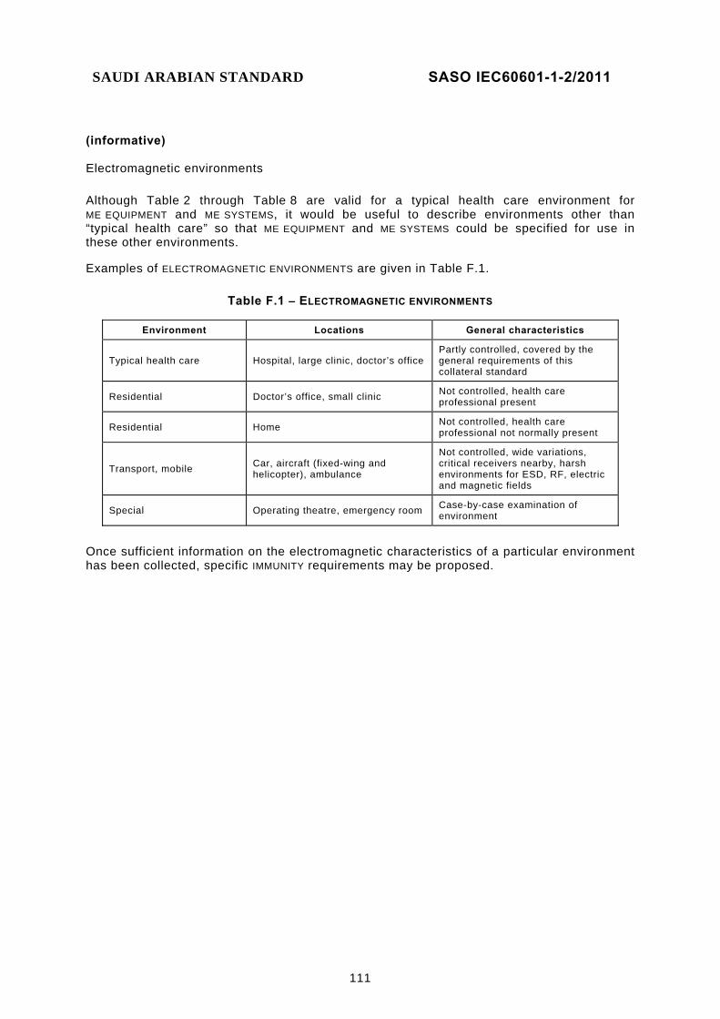
SAUDI ARABIAN STANDARD SASO IEC60601-1-2/2011
111
(informative) Electromagnetic environments
Although Table 2 through Table 8 are valid for a typical health care environment for ME EQUIPMENT and ME SYSTEMS, it would be useful to describe environments other than “typical health care” so that ME EQUIPMENT and ME SYSTEMS could be specified for use in these other environments.
Examples of ELECTROMAGNETIC ENVIRONMENTS are given in Table F.1.
Table F.1 – ELECTROMAGNETIC ENVIRONMENTS
Environment Locations General characteristics
Typical health care Hospital, large clinic, doctor’s office Partly controlled, covered by the general requirements of this collateral standard
Residential Doctor’s office, small clinic Not controlled, health care professional present
Residential Home Not controlled, health care professional not normally present
Transport, mobile Car, aircraft (fixed-wing and helicopter), ambulance
Not controlled, wide variations, critical receivers nearby, harsh environments for ESD, RF, electric and magnetic fields
Special Operating theatre, emergency room Case-by-case examination of environment
Once sufficient information on the electromagnetic characteristics of a particular environment has been collected, specific IMMUNITY requirements may be proposed.

SAUDI ARABIAN STANDARD SASO IEC60601-1-2/2011
112
(informative) Guidance for determining if electrical equipment that is not ME EQUIPMENT and that is used in an ME SYSTEM is exempt from the EMC testing requirements of this collateral standard
As specified in 4.1.2 and 6.2.1.4, electrical equipment that is not ME EQUIPMENT and that is supplied as part of an ME SYSTEM is exempt from the EMC testing requirements of this collateral standard, provided that the electrical equipment that is not ME EQUIPMENT complies with applicable international EMC standards, both the EMISSIONS and IMMUNITY of the electrical equipment that is not ME EQUIPMENT and that is used in an ME SYSTEM have been determined not to adversely affect the BASIC SAFETY or ESSENTIAL PERFORMANCE of the ME SYSTEM, and the EMISSIONS of the electrical equipment that is not ME EQUIPMENT have been determined not to cause the EMISSIONS of the ME SYSTEM to exceed applicable limits.
The flowchart in Figure G.1 is a graphical step-by-step procedure for determining if electrical equipment that is not ME EQUIPMENT and that is used in an ME SYSTEM is exempt from the EMC testing requirements of this collateral standard. The determination is as follows:
– If the electrical equipment that is not ME EQUIPMENT does not comply with applicable international EMC standards, it is not exempt from the EMC testing requirements of this collateral standard.
– If the electrical equipment that is not ME EQUIPMENT does comply with applicable international EMC standards but its EMISSIONS or IMMUNITY could adversely affect the BASIC SAFETY or ESSENTIAL PERFORMANCE of the ME SYSTEM, it is not exempt from the EMC testing requirements of this collateral standard.
– If the electrical equipment that is not ME EQUIPMENT does comply with applicable international EMC standards, its EMISSIONS or IMMUNITY could not adversely affect the BASIC SAFETY or ESSENTIAL PERFORMANCE of the ME SYSTEM, but its EMISSIONS could cause the EMISSIONS of the ME SYSTEM to exceed applicable limits, it is not exempt from the EMC testing requirements of this collateral standard.
– If the electrical equipment that is not ME EQUIPMENT does comply with applicable international EMC standards, its EMISSIONS or IMMUNITY could not adversely affect the BASIC SAFETY or ESSENTIAL PERFORMANCE of the ME SYSTEM, and its EMISSIONS could not cause the EMISSIONS of the ME SYSTEM to exceed applicable limits, it is exempt from the EMC testing requirements of this collateral standard.
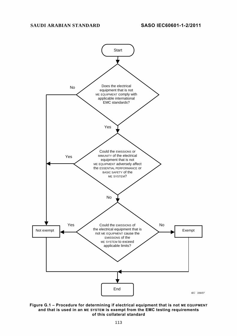
SAUDI ARABIAN STANDARD SASO IEC60601-1-2/2011
113
Start
Yes
No
Could the EMISSIONS or IMMUNITY of the electrical
equipment that is not ME EQUIPMENT adversely affect the ESSENTIAL PERFORMANCE or
BASIC SAFETY of the ME SYSTEM?
Does the electrical equipment that is not
ME EQUIPMENT comply with applicable international
EMC standards?
Could the EMISSIONS of
the electrical equipment that is not ME EQUIPMENT cause the
EMISSIONS of the ME SYSTEM to exceed
applicable limits?
Yes
Yes Not exempt Exempt
No
No
End IEC 336/07
Figure G.1 – Procedure for determining if electrical equipment that is not ME EQUIPMENT and that is used in an ME SYSTEM is exempt from the EMC testing requirements
of this collateral standard
SAUDI ARABIAN STANDARD SASO IEC60601-1-2/2011
114
(see 4.1.2 and 6.2.1.4)

SAUDI ARABIAN STANDARD SASO IEC60601-1-2/2011
115
(informative)
Mapping between the elements of the second edition of IEC 60601-1-2 as amended and
IEC 60601-1-2:2007
This annex contains a mapping of the clauses and subclause of the second edtion of IEC 60601-1-2 as amended to the comparable clauses and subclauses in this editon. Table H.1 is intended to provide a tool to assist users of IEC 60601-1-2 to trace requirements between this edition and their source in the second edition as amended.
Table H.1 – Mapping between the elements of the second edition of IEC 60601-1-2 as amended and IEC 60601-1-2:2007
IEC 60601-1-2 Second edition as amended IEC 60601-1-2:2007
Clause Title Clause Title
1 “Scope and object” 1 Scope, object and related standards
1.201 “Scope” 1.1 Scope
1.202 “Object” 1.2 Object
2 “Terminology and definitions” 3 Terms and definitions
2.201 "(immunity) compliance level" 3.1 (IMMUNITY) COMPLIANCE LEVEL
2.202 "Degredation (of performance)" 3.2 DEGRADATION (of performance)
2.203 "Effective radiated power (ERP)" 3.3 EFFECTIVE RADIATED POWER (ERP)
2.204 "Electromagnetic compatibility (EMC)" 3.4 ELECTROMAGNETIC COMPATIBILITY (EMC)
2.205 "Electromagnetic disturbance" 3.5 ELECTROMAGNETIC DISTURBANCE
2.206 "(Electromgnetic) emission" 3.6 (ELECTROMGNETIC) EMISSION
2.207 "Electromagnetic environment" 3.7 ELECTROMAGNETIC ENVIRONMENT
2.208 "Electromagnetic noise" 3.8 ELECTROMAGNETIC NOISE
2.209 "Electrostatic discharge" 3.9 ELECTROSTATIC DISCHARGE
2.211 "Exclusion band" 3.10 EXCLUSION BAND
2.212 "Function (of an equipment or system)" 3.11 FUNCTION
2.213 "IEC 60601 test level" 3.12 IEC 60601 TEST LEVEL
2.214 "Immunity (to a disturbance)" 3.13 IMMUNITY (to a disturbance)
2.215 "Immunity level" 3.14 IMMUNITY LEVEL
2.216 "Immunity test level" 3.15 IMMUNITY TEST LEVEL
2.217 "Information technology equipment (ITE)" 3.16 INFORMATION TECHNOLOGY EQUIPMENT (ITE)
2.218 "Large equipment or system" 3.17 LARGE ME EQUIPMENT or ME SYSTEM
2.219 "Life-supporting equipment or system" 3.18 LIFE-SUPPORTING ME EQUIPMENT or ME SYSTEM
2.220 "Low voltage" 3.19 LOW VOLTAGE
2.221 'Medical electrical system (hereinafter referred to as system)"
Defined in 3.64 of IEC 60601-1:2005.

SAUDI ARABIAN STANDARD SASO IEC60601-1-2/2011
116
Table H.1 – Mapping between the elements of the second edition of IEC 60601-1-2 as amended and IEC 60601-1-2:2007 (Continued)
IEC 60601-1-2 Second edition as amended IEC 60601-1-2:2007
Clause Title Clause Title
2.222 "Operating frequency" 3.20 OPERATING FREQUENCY
2.223 "Patient-coupled equipment or system" 3.21 PATIENT-COUPLED ME EQUIPMENT or ME SYSTEM
2.224 "Physiological simulation frequency" 3.22 PHYSIOLOGICAL SIMULATION FREQUENCY
2.225 "Public mains network" 3.24 PUBLIC MAINS NETWORK
2.226 "Radio frequency (RF)" 3.25 RADIO FREQUENCY (RF)
2.227 "Professional equipment or system" 3.23 PROFESSIONAL ME EQUIPMENT or ME SYSTEM
2.228 "Type A professional equipment or system" 3.26 TYPE A PROFESSIONAL ME EQUIPMENT or ME SYSTEM
3 "General requirements" 4 General requirements
3.201 "General requirements for electromagnetic compatibility of equipment and systems"
4.1 General requirements for ELECTROMAGNETIC COMPATIBILITY of ME EQUIPMENT and ME SYSTEMS
3.201.1 "Electromagnetic compatibility" 4.1.1 ELECTROMAGNETIC COMPATIBILITY
3.201.2 'Essential performance" Covered in 4.3 of IEC 60601-1:2005.
3.201.3 "Medical electrical equipment" Deleted and unnecessary.
3.201.4 'Non-medical electrical equipment" 4.1.2 Electrical equipment that is not ME EQUIPMENT
3.201.5 "General test conditions" 4.2 SINGLE FAULT CONDITION for ME EQUIPMENT
6 "Identification, marking and documents" 5. Identification, marking and documents
6.1.201 "Marking on the outside of equipment or equipment parts"
5.1 Marking on the outside of ME EQUIPMENT or ME EQUIPMENT parts
6.1.201.1 "Marking on the outside of equipment or equipment parts that include RF transmitters or that apply RF electromagnetic energy for diagnosis or treatment"
5.1.1 Marking on the outside of ME EQUIPMENT or ME EQUIPMENT parts that include RF transmitters or that apply RF electromagnetic energy for diagnosis or treatment
6.1.201.2 "Marking on the outside of equipment or equipment parts for which the connector testing exemption specified in 36.202.2 b) 3) is used"
5.1.2 Marking on the outside of ME EQUIPMENT or ME EQUIPMENT parts for which the connector testing exemption specified in 6.2.2.2 c) is used
6.1.201.3 "Marking on the outside of equipment and systems that are specified for use only in a shielded location"
5.1.3 Marking on the outside of ME EQUIPMENT and ME SYSTEMS that are specified for use only in a shielded location
6.8 "Accompanying documents" 5.2 ACCOMPANYING DOCUMENTS
6.8.2.201 "Instructions for use" 5.2.1 Instructions for use
6.8.2.201 a) "Requirements applicable to all equipment and systems"
5.2.1.1 Requirements applicable to all ME EQUIPMENT and ME SYSTEMS
6.8.2.201 b) Requirements applicable to equipment and systems for which the connector testing exemption specified in 36.202.2 b) 3) is used
5.2.1.2 Requirements applicable to ME EQUIPMENT and ME SYSTEMS for which the connector testing exemption specified in 6.2.2.2 c) is used
6.8.2.201 c) "Minimum amplitude or value of patient physiological signal"
5.2.1.3 Minimum amplitude or value of PATIENT physiological signal

SAUDI ARABIAN STANDARD SASO IEC60601-1-2/2011
117
Table H.1 – Mapping between the elements of the second edition of IEC 60601-1-2 as amended and IEC 60601-1-2:2007 (Continued)
IEC 60601-1-2 Second edition as amended IEC 60601-1-2:2007
Clause Title Clause Title
6.8.2.201 d) "Requirements applicable to type A professional equipment and systems"
5.2.1.4 Requirements applicable to TYPE A PROFESSIONAL ME EQUIPMENT and ME SYSTEMS
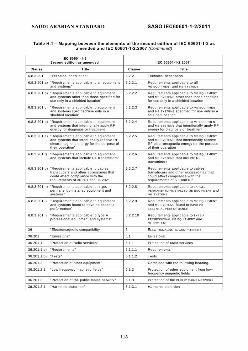
SAUDI ARABIAN STANDARD SASO IEC60601-1-2/2011
118
Table H.1 – Mapping between the elements of the second edition of IEC 60601-1-2 as amended and IEC 60601-1-2:2007 (Continued)
IEC 60601-1-2 Second edition as amended IEC 60601-1-2:2007
Clause Title Clause Title
6.8.3.201 "Technical description" 5.2.2 Technical description
6.8.3.201 a) "Requirements applicable to all equipment and systems"
5.2.2.1 Requirements applicable to all ME EQUIPMENT and ME SYSTEMS
6.8.3.201 b) "Requirements applicable to equipment and systems other than those specified for use only in a shielded location"
5.2.2.2 Requirements applicable to ME EQUIPMENT and ME SYSTEMS other than those specified for use only in a shielded location
6.8.3.201 c) "Requirements applicable to equipment and systems specified"use only in a shielded location"
5.2.2.3 Requirements applicable to ME EQUIPMENT and ME SYSTEMS specified for use only in a shielded location
6.8.3.201 d) "Requirements applicable to equipment and systems that intentionally apply RF energy for diagnosis or treatment"
5.2.2.4 Requirements applicable to ME EQUIPMENT and ME SYSTEMS that intentionally apply RF energy for diagnosis or treatment
6.8.3.201 e) "Requirements applicable to equipment and systems that intentionally receive RF electromagnetic energy for the purpose of their operation"
5.2.2.5 Requirements applicable to ME EQUIPMENT and ME SYSTEMS that intentionally receive RF electromagnetic energy for the purpose of their operation
6.8.3.201 f) "Requirements applicable to equipment and systems that include RF transmitters"
5.2.2.6 Requirements applicable to ME EQUIPMENT and ME SYSTEMS that include RF transmitters
6.8.3.201 g) "Requirements applicable to cables, transducers and other accessories that could affect compliance with the requirements of 36.201 and 36.202"
5.2.2.7 Requirements applicable to cables, transducers and other ACCESSORIES that could affect compliance with the requirements of 6.1 and 6.2
6.8.3.201 h) "Requirements applicable to large, permanently-installed equipment and systems"
5.2.2.8 Requirements applicable to LARGE, PERMANENTLY-INSTALLED ME EQUIPMENT and ME SYSTEMS
6.8.3.201 i) "Requirements applicable to equipment and systems found to have no essential performance"
5.2.2.9 Requirements applicable to ME EQUIPMENT and ME SYSTEMS found to have no ESSENTIAL PERFORMANCE
6.8.3.201 j) "Requirements applicable to type A professional equipment and systems"
5.2.2.10 Requirements applicable to TYPE A PROFESSIONAL ME EQUIPMENT and ME SYSTEMS
36 "Electromagnetic compatibility" 6 ELECTROMAGNETIC COMPATIBILITY
36.201 "Emissions" 6.1 EMISSIONS
36.201.1 "Protection of radio services" 6.1.1 Protection of radio services
36.201.1 a) "Requirements" 6.1.1.1 Requirements
36.201.1 b) "Tests" 6.1.1.2 Tests
36.201.2 "Protection of other equipment" Combined with the following heading.
36.201.2.1 "Low frequency magnetic fields" 6.1.2 Protection of other equipment from low-frequency magnetic fields
36.201.3 "Protection of the public mains network" 6.1.3 Protection of the PUBLIC MAINS NETWORK
36.201.3.1 "Harmonic distortion" 6.1.3.1 Harmonic distortion

SAUDI ARABIAN STANDARD SASO IEC60601-1-2/2011
119
Table H.1 – Mapping between the elements of the second edition of IEC 60601-1-2 as amended and IEC 60601-1-2:2007 (Continued)
IEC 60601-1-2 Second edition as amended IEC 60601-1-2:2007
Clause Title Clause Title
36.201.3.1 a) "Requirements" 6.1.3.1.1 Requirements
36.201.3.1 b) “Tests” 6.1.3.1.2 Tests
36.201.3.2 “Voltage fluctuations and flicker” 6.1.3.2 Voltage fluctuations and flicker
36.201.3.2 a) “Requirements” 6.1.3.2.1 Requirements
36.201.3.2 b) “Tests” 6.1.3.2.2 Tests
36.202 “Immunity” 6.2 IMMUNITY
36.202.1 “General” 6.2.1 General
36.202.1 a) “Immunity test levels” 6.2.1.1 IMMUNITY TEST LEVELS
36.202.1 b) “Documentation of the test” 6.2.1.2 Documentation of the test
36.202.1 c) “Operating mode and configuration” 6.2.1.3 Operating mode and configuration
36.202.1 d) “Non-medical electrical equipment” 6.2.1.4 Electrical equipment that is not ME EQUIPMENT
36.202.1 e) “Patient-coupled equipment and systems” 6.2.1.5 PATIENT-COUPLED ME EQUIPMENT and ME SYSTEMS
36.202.1 f) “Variable gain” 6.2.1.6 Variable gain
36.202.1 g) “Patient simulation” 6.2.1.7 PATIENT simulation
36.202.1 h) “Testing of normally non-observable functions”
6.2.1.8 Testing of normally non-observable FUNCTIONS
36.202.1 i) “Sub-systems” 6.2.1.9 Subsystems
36.202.1 j) “Compliance criteria” 6.2.1.10 Compliance criteria
36.202.1 k) “Equipment and systems that include radio equipment”
6.2.1.11 ME EQUIPMENT and ME SYSTEMS that include radio equipment
36.202.2 “Electrostatic discharge (ESD)” 6.2.2 ELECTROSTATIC DISCHARGE (ESD)
36.202.2 a) “Requirements” 6.2.2.1 Requirements
36.202.2 b) “Tests” 6.2.2.2 Tests
36.202.3 Radiated RF electromagnetic fields 6.2.3 Radiated RF electromagnetic fields
36.202.3 a) “Requirements” 6.2.3.1 Requirements
36.202.3 b) “Tests” 6.2.3.2 Tests
36.202.4 Electrical fast transients and bursts 6.2.4 Electrical fast transients and bursts
36.202.4 a) “Requirements” 6.2.4.1 Requirements
36.202.4 b) “Tests” 6.2.4.2 Tests
36.202.5 “Surges” 6.2.5 Surges
36.202.5 a) “Requirements” 6.2.5.1 Requirements
36.202.5 b) “Tests” 6.2.5.2 Tests
36.202.6 “Conducted disturbances, induced by RF fields”
6.2.6 Conducted disturbances, induced by RF fields
36.202.6 a) “Requirements” 6.2.6.1 Requirements
36.202.6 b) “Tests” 6.2.6.2 Tests
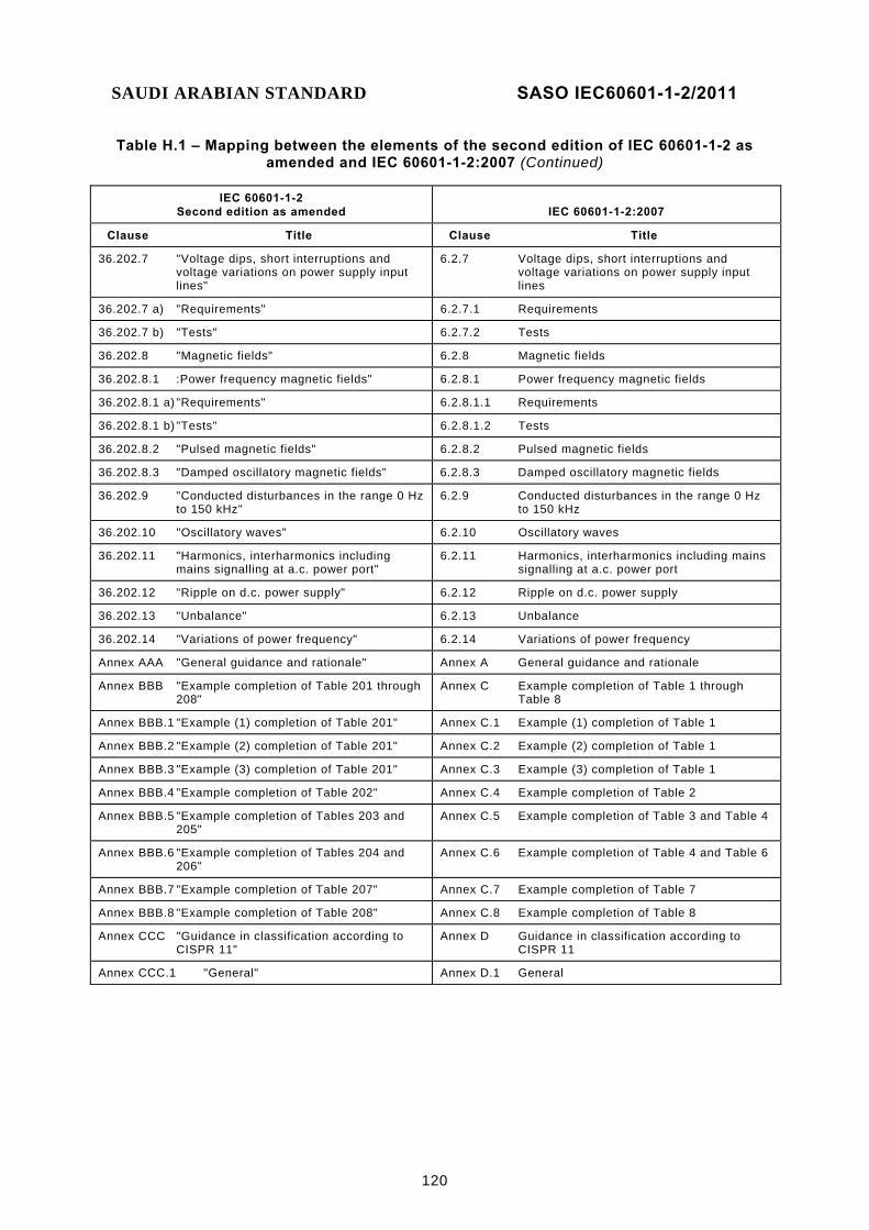
SAUDI ARABIAN STANDARD SASO IEC60601-1-2/2011
120
Table H.1 – Mapping between the elements of the second edition of IEC 60601-1-2 as amended and IEC 60601-1-2:2007 (Continued)
IEC 60601-1-2 Second edition as amended IEC 60601-1-2:2007
Clause Title Clause Title
36.202.7 "Voltage dips, short interruptions and voltage variations on power supply input lines"
6.2.7 Voltage dips, short interruptions and voltage variations on power supply input lines
36.202.7 a) "Requirements" 6.2.7.1 Requirements
36.202.7 b) "Tests" 6.2.7.2 Tests
36.202.8 "Magnetic fields" 6.2.8 Magnetic fields
36.202.8.1 :Power frequency magnetic fields" 6.2.8.1 Power frequency magnetic fields
36.202.8.1 a) "Requirements" 6.2.8.1.1 Requirements
36.202.8.1 b) "Tests" 6.2.8.1.2 Tests
36.202.8.2 "Pulsed magnetic fields" 6.2.8.2 Pulsed magnetic fields
36.202.8.3 "Damped oscillatory magnetic fields" 6.2.8.3 Damped oscillatory magnetic fields
36.202.9 "Conducted disturbances in the range 0 Hz to 150 kHz"
6.2.9 Conducted disturbances in the range 0 Hz to 150 kHz
36.202.10 "Oscillatory waves" 6.2.10 Oscillatory waves
36.202.11 "Harmonics, interharmonics including mains signalling at a.c. power port"
6.2.11 Harmonics, interharmonics including mains signalling at a.c. power port
36.202.12 "Ripple on d.c. power supply" 6.2.12 Ripple on d.c. power supply
36.202.13 "Unbalance" 6.2.13 Unbalance
36.202.14 "Variations of power frequency" 6.2.14 Variations of power frequency
Annex AAA "General guidance and rationale" Annex A General guidance and rationale
Annex BBB "Example completion of Table 201 through 208"
Annex C Example completion of Table 1 through Table 8
Annex BBB.1 "Example (1) completion of Table 201" Annex C.1 Example (1) completion of Table 1
Annex BBB.2 "Example (2) completion of Table 201" Annex C.2 Example (2) completion of Table 1
Annex BBB.3 "Example (3) completion of Table 201" Annex C.3 Example (3) completion of Table 1
Annex BBB.4 "Example completion of Table 202" Annex C.4 Example completion of Table 2
Annex BBB.5 "Example completion of Tables 203 and 205"
Annex C.5 Example completion of Table 3 and Table 4
Annex BBB.6 "Example completion of Tables 204 and 206"
Annex C.6 Example completion of Table 4 and Table 6
Annex BBB.7 "Example completion of Table 207" Annex C.7 Example completion of Table 7
Annex BBB.8 "Example completion of Table 208" Annex C.8 Example completion of Table 8
Annex CCC "Guidance in classification according to CISPR 11"
Annex D Guidance in classification according to CISPR 11
Annex CCC.1 "General" Annex D.1 General

SAUDI ARABIAN STANDARD SASO IEC60601-1-2/2011
121
Table H.1 – Mapping between the elements of the second edition of IEC 60601-1-2 as amended and IEC 60601-1-2:2007 (Continued)
IEC 60601-1-2 Second edition as amended IEC 60601-1-2:2007
Clause Title Clause Title
Annex CCC.2 "Separation into groups" Annex D.2 Separation into groups
Annex CCC.3 "Division into classes" Annex D.3 Division into classes
Annex DDD "Guidance in the application of IEC 60601-1-2 to particular standards"
Annex E Guidance in the application of IEC 60601-1-2 to particular standards
Annex DDD.1 "General" Annex E.1 General
Annex DDD.2 "Recommended modifications" Annex E.2 Recommended modifications
Annex DDD.3 "Cautions" Annex E.3 Cautions
Annex DDD.4 Additional recommendations Annex E.4 Additional recommendations
Annex EEE "Electromagnetic environments" Annex F ELECTROMAGNETIC ENVIRONMENTS
Annex FFF "Normative references" 2 Normative references
Annex GGG "Guidance in the identification of essential performance"
Deleted
Annex HHH "Guidance for determining if electrical equipment that is not equipment and that is used in an system is exempt from the EMC testing requirements of this collateral standard"
Annex G Guidance for determining if electrical equipment that is not ME EQUIPMENT and that is used in an ME SYSTEM is exempt from the EMC testing requirements of this collateral standard
Bibliography Bibliography
Figure 201 "Instructions for completing Table 201 for CISPR 11 equipment and systems"
Figure 1 Instructions for completing Table 1 for CISPR 11 ME EQUIPMENT and ME SYSTEMS
Figure 202 "Instructions for completing Table 201 for CISPR 14 and CISPR 15 me equipment"
Figure 2 Instructions for completing Table 1 for CISPR 14 and CISPR 15 ME EQUIPMENT
Figure 203 "Instructions for completing Table 202" Figure 3 Instructions for completing Table 2
Figure 204 "Instructions for completing Tables 203 and 205 for life-supporting equipment and systems"
Figure 4 Instructions for completing Table 3 and Table 5 for LIFE-SUPPORTING ME EQUIPMENT and ME SYSTEMS
Figure 205 "Instructions for completing Tables 204 and 206 for equipment and systems that are not life-supporting"
Figure 5 Instructions for completing Table 4 and Table 6 for ME EQUIPMENT and ME SYSTEMS that are not LIFE-SUPPORTING
Figure AAA.1 "Example of cable arrangement for radiated immunity test"
Figure A.1 Example of cable arrangement for radiated IMMUNITY test
Figure AAA.2 "Examples showing maximum dimension for equipment with one and with two cables"
Figure A.2 Examples showing maximum dimension for ME EQUIPMENT with one and with two cables
Figure HHH.1 "Procedure for determining if electrical equipment that is not equipment and that is used in an system is exempt from the EMC testing requirements of this collateral standard"
Figure G.1 Procedure for determining if electrical equipment that is not ME EQUIPMENT and that is used in an ME SYSTEM is exempt from the EMC testing requirements of this collateral standard
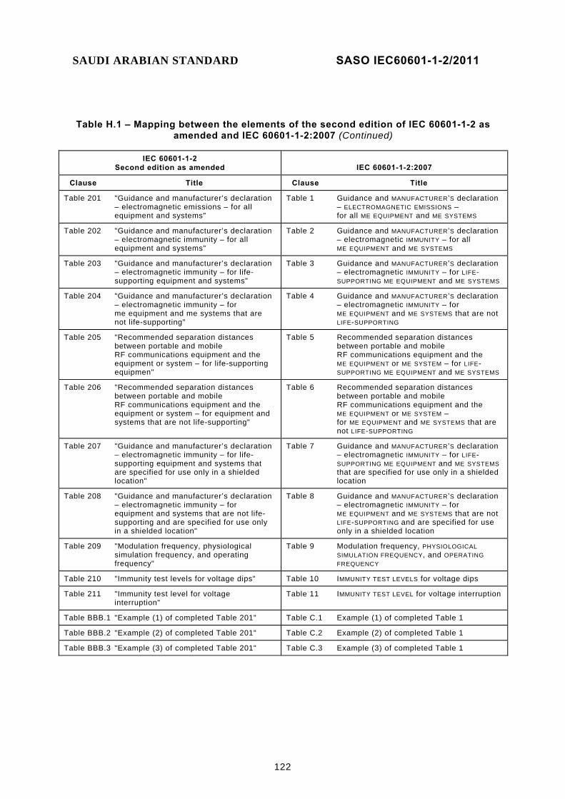
SAUDI ARABIAN STANDARD SASO IEC60601-1-2/2011
122
Table H.1 – Mapping between the elements of the second edition of IEC 60601-1-2 as amended and IEC 60601-1-2:2007 (Continued)
IEC 60601-1-2 Second edition as amended IEC 60601-1-2:2007
Clause Title Clause Title
Table 201 "Guidance and manufacturer’s declaration – electromagnetic emissions – for all equipment and systems"
Table 1 Guidance and MANUFACTURER’S declaration – ELECTROMAGNETIC EMISSIONS – for all ME EQUIPMENT and ME SYSTEMS
Table 202 "Guidance and manufacturer’s declaration – electromagnetic immunity – for all equipment and systems"
Table 2 Guidance and MANUFACTURER’S declaration – electromagnetic IMMUNITY – for all ME EQUIPMENT and ME SYSTEMS
Table 203 "Guidance and manufacturer’s declaration – electromagnetic immunity – for life-supporting equipment and systems"
Table 3 Guidance and MANUFACTURER’S declaration – electromagnetic IMMUNITY – for LIFE-SUPPORTING ME EQUIPMENT and ME SYSTEMS
Table 204 "Guidance and manufacturer’s declaration – electromagnetic immunity – for me equipment and me systems that are not life-supporting"
Table 4 Guidance and MANUFACTURER’S declaration – electromagnetic IMMUNITY – for ME EQUIPMENT and ME SYSTEMS that are not LIFE-SUPPORTING
Table 205 "Recommended separation distances between portable and mobile RF communications equipment and the equipment or system – for life-supporting equipmen"
Table 5 Recommended separation distances between portable and mobile RF communications equipment and the ME EQUIPMENT or ME SYSTEM – for LIFE-SUPPORTING ME EQUIPMENT and ME SYSTEMS
Table 206 "Recommended separation distances between portable and mobile RF communications equipment and the equipment or system – for equipment and systems that are not life-supporting"
Table 6 Recommended separation distances between portable and mobile RF communications equipment and the ME EQUIPMENT or ME SYSTEM – for ME EQUIPMENT and ME SYSTEMS that are not LIFE-SUPPORTING
Table 207 "Guidance and manufacturer’s declaration – electromagnetic immunity – for life-supporting equipment and systems that are specified for use only in a shielded location"
Table 7 Guidance and MANUFACTURER’S declaration – electromagnetic IMMUNITY – for LIFE-SUPPORTING ME EQUIPMENT and ME SYSTEMS that are specified for use only in a shielded location
Table 208 "Guidance and manufacturer’s declaration – electromagnetic immunity – for equipment and systems that are not life-supporting and are specified for use only in a shielded location"
Table 8 Guidance and MANUFACTURER’S declaration – electromagnetic IMMUNITY – for ME EQUIPMENT and ME SYSTEMS that are not LIFE-SUPPORTING and are specified for use only in a shielded location
Table 209 "Modulation frequency, physiological simulation frequency, and operating frequency"
Table 9 Modulation frequency, PHYSIOLOGICAL SIMULATION FREQUENCY, and OPERATING FREQUENCY
Table 210 "Immunity test levels for voltage dips" Table 10 IMMUNITY TEST LEVELS for voltage dips
Table 211 "Immunity test level for voltage interruption"
Table 11 IMMUNITY TEST LEVEL for voltage interruption
Table BBB.1 "Example (1) of completed Table 201" Table C.1 Example (1) of completed Table 1
Table BBB.2 "Example (2) of completed Table 201" Table C.2 Example (2) of completed Table 1
Table BBB.3 "Example (3) of completed Table 201" Table C.3 Example (3) of completed Table 1
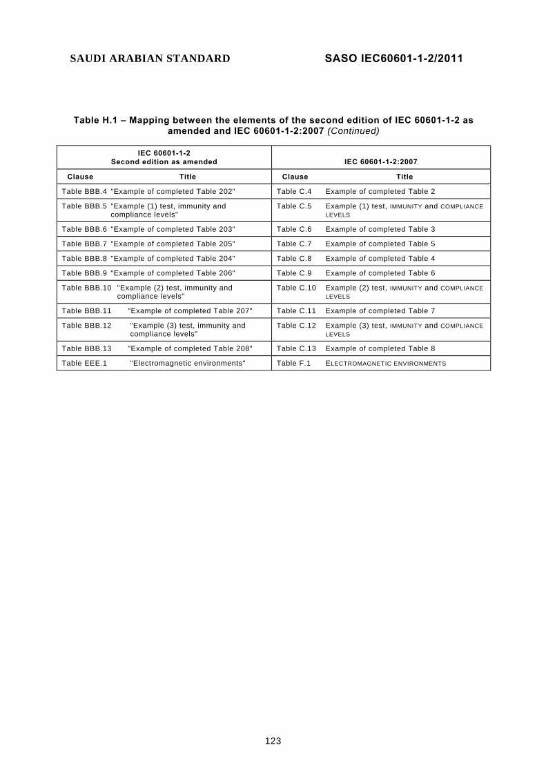
SAUDI ARABIAN STANDARD SASO IEC60601-1-2/2011
123
Table H.1 – Mapping between the elements of the second edition of IEC 60601-1-2 as amended and IEC 60601-1-2:2007 (Continued)
IEC 60601-1-2 Second edition as amended IEC 60601-1-2:2007
Clause Title Clause Title
Table BBB.4 "Example of completed Table 202" Table C.4 Example of completed Table 2
Table BBB.5 "Example (1) test, immunity and compliance levels"
Table C.5 Example (1) test, IMMUNITY and COMPLIANCE LEVELS
Table BBB.6 "Example of completed Table 203" Table C.6 Example of completed Table 3
Table BBB.7 "Example of completed Table 205" Table C.7 Example of completed Table 5
Table BBB.8 "Example of completed Table 204" Table C.8 Example of completed Table 4
Table BBB.9 "Example of completed Table 206" Table C.9 Example of completed Table 6
Table BBB.10 "Example (2) test, immunity and compliance levels"
Table C.10 Example (2) test, IMMUNITY and COMPLIANCE LEVELS
Table BBB.11 "Example of completed Table 207" Table C.11 Example of completed Table 7
Table BBB.12 "Example (3) test, immunity and compliance levels"
Table C.12 Example (3) test, IMMUNITY and COMPLIANCE LEVELS
Table BBB.13 "Example of completed Table 208" Table C.13 Example of completed Table 8
Table EEE.1 "Electromagnetic environments" Table F.1 ELECTROMAGNETIC ENVIRONMENTS

SAUDI ARABIAN STANDARD SASO IEC60601-1-2/2011
124
Bibliography
[1] CISPR 11:2003, Industrial, scientific and medical (ISM) radio-frequency equipment – Electromagnetic disturbance characteristics – Limits and methods of measurement 12) Amendment 1 (2004) Amendment 2 (2006)
[2] CISPR 24, Information technology equipment – Immunity characteristics – Limits and methods of measurement
[3] IEC 60050-161:1990, International Electrotechnical Vocabulary (IEV) – Chapter 161: Electromagnetic compatibility Amendment 1 (1997) Amendment 2 (1998)
[4] IEC 61000-1-2:2001, Electromagnetic compatibility (EMC) – Part 1-2: General – Methodology for the achievement of the functional safety of electrical and electronic equipment with regard to electromagnetic phenomena
[5] IEC 61000-4-2:1995, Electromagnetic compatibility (EMC) – Part 4: Testing and measurement techniques – Section 2: Electrostatic discharge immunity test 13) Amendment 1 (1998) Amendment 2 (2000)
[6] IEC 61000-4-3:2006, Electromagnetic compatibility (EMC) – Part 4-3: Testing and measurement techniques – Radiated, radio-frequency, electromagnetic field immunity test
[7] IEC 61000-4-4:2004, Electromagnetic compatibility (EMC) – Part 4-4: Testing and measurement techniques – Electrical fast transient/burst immunity test
[8] IEC 61000-4-6:2003, Electromagnetic compatibility (EMC) – Part 4-6: Testing and measurement techniques – Immunity to conducted disturbances, induced by radio-frequency fields 14) Amendment 1 (2004) Amendment 2 (2006)
[9] IEC 61326-1, Electrical equipment for measurement, control and laboratory use – EMC requirements – Part 1: General requirements
[10] ISO 14971, Medical devices – Application of risk management to medical devices [11] ITU:1998, Radio Regulations – Volume 2: Appendices [12] ANSI/IEEE 100:1996, Standard Dictionary of Electrical and Electronics Terms [13] ETSI I-ETS 300 220:1993, Radio Equipment and Systems (RES); Short Range
Devices (SRDs); Technical characteristics and test methods for radio equipment to be used in the 25 MHz to 1 000 MHz frequency range with power levels ranging up to 500 mW
[14] ETSI ETS 300 741:1998, Electromagnetic Compatibility and Radio Spectrum Matters (ERM); ElectroMagnetic Compatibility (EMC) Standard for Wide-Area Paging Equipment
[15] European Union Council Directive 73/23/EEC of 19 February 1973 on the harmonization of the laws of Member States relating to electrical equipment designed for use within certain voltage limits
__________ 12) There exists a consolidated edition 4.1 (2004) that includes CISPR 11:2003 and its Amendment 1 (2004) 13) There exists a consolidated edition 1.2 (2001) that includes IEC 61000-4-2 (1995) and its Amendment 1 (1998) and Amendment 2 (2000). 14) There exists a consolidated edition 2.2 (2006) that includes IEC 61000-4-6 (2003) and its Amendment 1 (2004)
and Amendment 2 (2006).
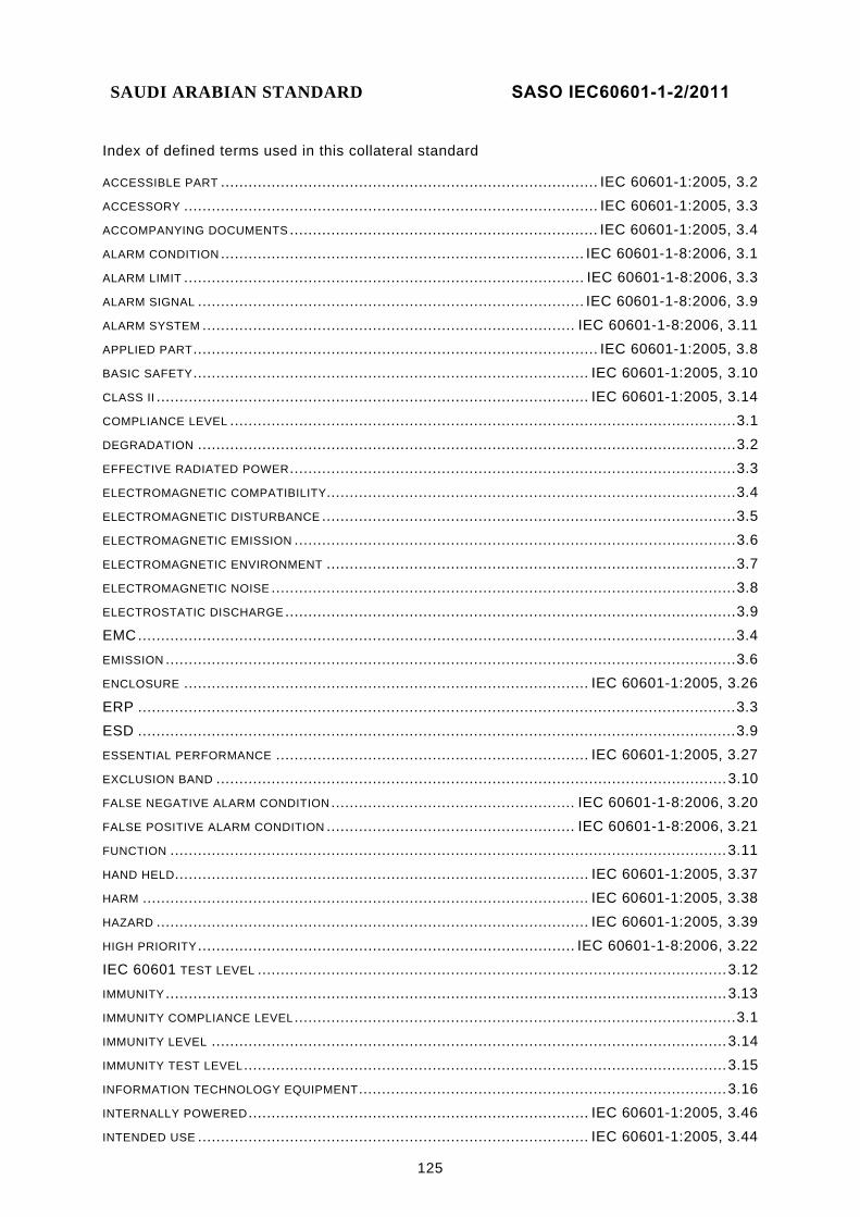
SAUDI ARABIAN STANDARD SASO IEC60601-1-2/2011
125
Index of defined terms used in this collateral standard
ACCESSIBLE PART .................................................................................. IEC 60601-1:2005, 3.2 ACCESSORY .......................................................................................... IEC 60601-1:2005, 3.3 ACCOMPANYING DOCUMENTS ................................................................... IEC 60601-1:2005, 3.4 ALARM CONDITION ............................................................................... IEC 60601-1-8:2006, 3.1 ALARM LIMIT ....................................................................................... IEC 60601-1-8:2006, 3.3 ALARM SIGNAL .................................................................................... IEC 60601-1-8:2006, 3.9 ALARM SYSTEM ................................................................................. IEC 60601-1-8:2006, 3.11 APPLIED PART ........................................................................................ IEC 60601-1:2005, 3.8 BASIC SAFETY ...................................................................................... IEC 60601-1:2005, 3.10 CLASS II .............................................................................................. IEC 60601-1:2005, 3.14 COMPLIANCE LEVEL .............................................................................................................. 3.1 DEGRADATION ..................................................................................................................... 3.2 EFFECTIVE RADIATED POWER ................................................................................................. 3.3 ELECTROMAGNETIC COMPATIBILITY......................................................................................... 3.4 ELECTROMAGNETIC DISTURBANCE .......................................................................................... 3.5 ELECTROMAGNETIC EMISSION ................................................................................................ 3.6 ELECTROMAGNETIC ENVIRONMENT ......................................................................................... 3.7 ELECTROMAGNETIC NOISE ..................................................................................................... 3.8 ELECTROSTATIC DISCHARGE .................................................................................................. 3.9 EMC .................................................................................................................................. 3.4 EMISSION ............................................................................................................................ 3.6 ENCLOSURE ........................................................................................ IEC 60601-1:2005, 3.26 ERP .................................................................................................................................. 3.3 ESD .................................................................................................................................. 3.9 ESSENTIAL PERFORMANCE .................................................................... IEC 60601-1:2005, 3.27 EXCLUSION BAND ............................................................................................................... 3.10 FALSE NEGATIVE ALARM CONDITION ..................................................... IEC 60601-1-8:2006, 3.20 FALSE POSITIVE ALARM CONDITION ...................................................... IEC 60601-1-8:2006, 3.21 FUNCTION ......................................................................................................................... 3.11 HAND HELD.......................................................................................... IEC 60601-1:2005, 3.37 HARM ................................................................................................. IEC 60601-1:2005, 3.38 HAZARD .............................................................................................. IEC 60601-1:2005, 3.39 HIGH PRIORITY .................................................................................. IEC 60601-1-8:2006, 3.22 IEC 60601 TEST LEVEL ...................................................................................................... 3.12 IMMUNITY .......................................................................................................................... 3.13 IMMUNITY COMPLIANCE LEVEL ................................................................................................ 3.1 IMMUNITY LEVEL ................................................................................................................ 3.14 IMMUNITY TEST LEVEL ......................................................................................................... 3.15 INFORMATION TECHNOLOGY EQUIPMENT ................................................................................ 3.16 INTERNALLY POWERED .......................................................................... IEC 60601-1:2005, 3.46 INTENDED USE ..................................................................................... IEC 60601-1:2005, 3.44

SAUDI ARABIAN STANDARD SASO IEC60601-1-2/2011
126
ITE ................................................................................................................................. 3.16

SAUDI ARABIAN STANDARD SASO IEC60601-1-2/2011
127
LARGE ME EQUIPMENT or ME SYSTEM ................................................................................... 3.17 LEAKAGE CURRENT ............................................................................... IEC 60601-1:2005, 3.47 LIFE-SUPPORTING ME EQUIPMENT or ME SYSTEM ................................................................... 3.18 LOW VOLTAGE ................................................................................................................... 3.19 MAINS VOLTAGE ................................................................................... IEC 60601-1:2005, 3.54 MANUFACTURER .................................................................................. IEC 60601-1:2005, 3.55 ME EQUIPMENT .................................................................................... IEC 60601-1:2005, 3.63 ME SYSTEM ......................................................................................... IEC 60601-1:2005, 3.64 MEDIUM PRIORITY .............................................................................. IEC 60601-1-8:2006, 3.28 MODEL OR TYPE REFERENCE ................................................................. IEC 60601-1:2005, 3.66 NOMINAL ............................................................................................. IEC 60601-1:2005, 3.69 NORMAL CONDITION .............................................................................. IEC 60601-1:2005, 3.70 NORMAL USE ....................................................................................... IEC 60601-1:2005, 3.71 OPERATING FREQUENCY...................................................................................................... 3.20 OPERATOR .......................................................................................... IEC 60601-1:2005, 3.73 PATIENT .............................................................................................. IEC 60601-1:2005, 3.76 PATIENT-COUPLED ME EQUIPMENT or ME SYSTEM ................................................................... 3.21 PERMANENTLY INSTALLED ..................................................................... IEC 60601-1:2005, 3.84 PHYSIOLOGICAL SIMULATION FREQUENCY .............................................................................. 3.22 POTENTIAL EQUALIZATION CONDUCTOR ................................................... IEC 60601-1:2005, 3.86 POWER SUPPLY CORD ........................................................................... IEC 60601-1:2005, 3.87 PROCESS ............................................................................................ IEC 60601-1:2005, 3.89 PROFESSIONAL ME EQUIPMENT or ME SYSTEM ....................................................................... 3.23 PROTECTIVE EARTH CONDUCTOR ............................................................ IEC 60601-1:2005, 3.93 PUBLIC MAINS NETWORK ..................................................................................................... 3.24 RADIO FREQUENCY ............................................................................................................. 3.25 RATED ................................................................................................ IEC 60601-1:2005, 3.97 RESPONSIBLE ORGANIZATION ............................................................... IEC 60601-1:2005, 3.101 RF ................................................................................................................................. 3.25 RISK ................................................................................................. IEC 60601-1:2005, 3.102 RISK ANALYSIS ................................................................................... IEC 60601-1:2005, 3.103 RISK MANAGEMENT ............................................................................. IEC 60601-1:2005, 3.107 SINGLE FAULT CONDITION .................................................................... IEC 60601-1:2005, 3.116 TOOL ................................................................................................ IEC 60601-1:2005, 3.127 TYPE A PROFESSIONAL ME EQUIPMENT or ME SYSTEM ............................................................. 3.26
___________