
International Mediation Institute Professional Mediation Worldwide.

HAL Id: hal-01207440https://hal-mines-albi.archives-ouvertes.fr/hal-01207440
Submitted on 1 Oct 2015
HAL is a multi-disciplinary open accessarchive for the deposit and dissemination of sci-entific research documents, whether they are pub-lished or not. The documents may come fromteaching and research institutions in France orabroad, or from public or private research centers.
L’archive ouverte pluridisciplinaire HAL, estdestinée au dépôt et à la diffusion de documentsscientifiques de niveau recherche, publiés ou non,émanant des établissements d’enseignement et derecherche français ou étrangers, des laboratoirespublics ou privés.
Mediation Information System Engineering based onHybrid Service Composition Mechanism
Nicolas Boissel-Dallier, Frederick Benaben, Jean-Pierre Lorré, Hervé Pingaud
To cite this version:Nicolas Boissel-Dallier, Frederick Benaben, Jean-Pierre Lorré, Hervé Pingaud. Mediation Informa-tion System Engineering based on Hybrid Service Composition Mechanism. Journal of Systems andSoftware, Elsevier, 2015, 108, pp.39-59. �10.1016/j.jss.2015.05.064�. �hal-01207440�
Mediation Information System Engineering based on
Hybrid Service Composition Mechanism✩
Nicolas Boissel-Dalliera,b,∗, Frederick Benabena, Jean-Pierre Lorreb, HervePingauda
aUniversite de Toulouse - Mines Albi, 4 route de Teillet, 81000 Albi, FrancebLinagora Toulouse, 3 Av Didier Daurat, 31000 Toulouse, France
Abstract
With the expansion of service-based information systems and the need for orga-nizations to collaborate with external partners, the alignment of business withIT has become crucial. This paper presents a hybrid service composition mech-anism, which couples logic-based and syntactic matchmaking of services andmessages in order to transform business processes into executable workflows byensuring service interoperability. This mechanism is based on both top-downand bottom-up approaches, with a view to meeting business requirements foraccess to available technical services, using a generic semantic profile as a pivotalmodel. Whereas service matchmaking focuses on functional coverage of gener-ated workflow, message matchmaking involves the generation of the requiredmessage transformation.
Keywords: semantic web services, hybrid matchmaking, business processmanagement, interoperability, mediation, information systems
1. Introduction
In today’s wide-open business ecosystem, the ability to collaborate withpotential partners is a crucial requirement for organizations. Furthermore, col-laboration between organizations must be reactive (to seize any relevant collab-oration opportunity) and flexible (to remain pertinent to the ongoing situation).In addition, due to the crucial position of information systems (ISs) in organi-zations nowadays, collaboration between organizations is highly dependent onthe ability of their ISs to collaborate [1][2]. For these reasons, the concept ofmediation could be extended to the IS domain through a mediation informationsystem (MIS) in charge of providing interoperability to the partners ISs. Such a
✩This document is a collaborative effort.∗Corresponding authorEmail addresses: [email protected] (Nicolas Boissel-Dallier),
[email protected] (Frederick Benaben), [email protected](Jean-Pierre Lorre), [email protected] (Herve Pingaud)
Preprint submitted to Elsevier November 9, 2012
*ManuscriptClick here to view linked References

mediator should be able to deal with information management, function sharingand process orchestration in a reactive and flexible way (to support the poten-tial collaboration efficiently). The MISE 2.0 project (for MIS Engineering) dealswith the design of such an MIS. MISE 2.0 is based on a model-driven engineer-ing (MDE) approach, dedicated to providing reactivity (by ensuring automatedmodel transformation) and is structured according to the following layers:
• Knowledge gathering (situation layer): collect information concerning thecollaborative situation,
• Process cartography design (solution layer): design the processes accord-ing to the knowledge gathered,
• MIS deployment (implementation layer): implement an IT structure ableto run the process cartography.
The transitions between these layers are the sticking points of this approach:driving an MDE approach in order to deploy a SOA system requires (i) design-ing a relevant business process cartography from the dedicated situation (firstgap) and (ii), from the obtained business processes involving business activities,designing a set of executable workflows invoking technical services (second gap).The first gap is managed at the abstract level of MISE 2.0 while the second ismanaged at the concrete level of MISE 2.0. By filling both these gaps, one canassume that reactivity can be managed.
Furthermore, MISE 2.0 deployment is based on a service-oriented archi-tecture (SOA) dedicated to providing flexibility (by bridging the gap betweendesign-time and run-time). The use of SOA allows deployment, on the sameplatform, of both services dedicated to design-time and services dedicated torun-time. Design-time services include a collaborative situation editor (dedi-cated to gathering collaborative knowledge and to modelling the collaborativesituation), a business transformation service (dedicated to deducing the processcartography from the collaborative situation model) and a technical transforma-tion service (dedicated to building the executable workflow files from the processcartography). Run-time services include all the technical services that can beinvoked to orchestrate the workflow files. Based on this architecture, flexibilitycan be assumed: if an adaptation is required, run-time workflow orchestrationcan be interrupted and, depending on the nature of the adaptation required, anydesign-time service can be invoked in order to re-design new run-time workflows.
This article will focus on reactivity issues at the concrete level. Our method-ology, explained in Section 3 after a presentation of the study context (Section2), aims at generating executable workflows from business processes. In orderto perform this transformation, we first have to bring semantic information toour source models, thanks to our semantic annotation mechanism presented inSection 4. After that, we can make use of this knowledge to find technicalservices which fit our business needs (see Section 5). In order to ensure goodcommunication between these services, we then use our message matchmakingengine, detailed in Section 6. Finally, Section 7 concludes and presents researchperspectives.
2
2. Positioning and related work
2.1. Mediation Information System Engineering and Interoperability
The first iteration of the MISE project (MISE 1.0, 2006-2010), did providefour design-time services which aimed to (i) characterize a collaborative situa-tion based on a dedicated ontology[3], (ii) extract and transform the knowledgeembedded in that ontology in order to model a collaborative business process[3],(iii) transform that collaborative business process model into a logical UML(Unified Modeling Language) model of the mediation information system [4]and finally (iv) transform this logical model into the files required for the de-ployment of an ESB (Enterprise Service Bus) giving efficient support to thecollaborative situation[5]. However, in the first iteration, there were some weakpoints:
• The collaborative situation ontology is mainly based on the MIT processontology handbook[6] and is thus essentially dedicated to manufacturingcontexts.
• There is only one single collaborative process diagram deduced at the busi-ness level (merging decisional, operational and support considerations).
• Matching between business activities (included in the business collabora-tive process model) and technical services (included in the workflow modeland deployed on an ESB) is a manual action.
• Detection of events requiring adaptation and flexibility mechanisms is alsoa human task.
The second iteration of MISE (MISE 2.0, started in 2009) aims at using theresults of MISE 1.0 in order to improve these four drawbacks. As explained inthe introduction, it is based on two levels (abstract and concrete), dealing withthe two transitions between three layers (situation, solution and implementa-tion).
• By defining our own collaborative situation ontology, we aim to overcomethe first drawback[7].
• By using the ISO standard, we aim to deduce a full process cartography(covering decisional, operational and support levels) and thus mitigate thesecond drawback[7].
• By using semantic annotation of business activities, business information,technical services and technical information, we seek to manage the seman-tic reconciliation mechanisms [8], in order to avoid the third drawback.
• By using an event-driven architecture, we aim to manage events and au-tomatically detect any needs for adaptation[5]. The fourth drawback canthen be avoided.
The current article specifically addresses the third point concerning semanticreconciliation.
3

2.2. Suitable solution for multiple application domains
Thanks to its flexible and adaptable mechanism, this approach is suitablefor any application domain. A first iteration of this mechanism was devel-oped during the ISTA3 project, which focused on sub-contractor collaborationand insisted on information system interoperability as collaboration support [9].This project only addressed the question of semantic reconciliation (service dis-covery and message transformation generation) and focussed on the industrialenvironment (limited agility needs, few potential services, basic performances).This implementation is currently being improved in order to meet more de-manding activity domains such as nuclear crisis management[10] or transportissues[11]. As well as those projects needing service and message matchmaking,these studies also took an interest in the other features of MISE 2.0 such asbusiness process generation and event-driven architecture. These features allowthe system to detect technical or business problems quickly, analyse them, andthen adapt itself accordingly.
2.3. Semantic reconciliation: state of the art
With the expansion of SOA architectures and BPM approaches, web servicediscovery and composition has become a key factor for IT alignment. A lot ofprojects focus on it, most of them taking an interest in SWS possibilities.
Service discovery and selection focuses on 1-to-1 service searches dependingon functional or non-functional parameters. All service searches are seen in-dependently: neither service exchanges nor message formats are involved here.The SAWSDL-MX2 [12], METEOR-S [13] and FUSION [14] projects take aninterest in SAWSDL service discovery. Whereas [13] focuses on syntactic match-ing based on input and output study only, [14] and [12] both provide a hybridsemantic matchmaking (i.e. coupling logic-based reasoning and syntactic sim-ilarity measurement results for better precision), using additional informationsuch as service function. OWLS-MX [15] and WSMO-MX [16] use mechanismssimilar to that used by [12] and (hybrid semantic matchmaking), respectively forOWL-S and WSMO. These semantic representations allow a higher expressionrange than SAWSDL. They allow [15] and [16] to use more information, such asservice precondition and effect, to perform service matchmaking. They generateheavy algorithms but improve precision and research possibilities. While previ-ous discovery mechanisms only focussed on functional properties, YASA-M [17]also considers non-functional requirements thanks to its semantic annotationmodel YASA, an extension of SAWSDL.
Service composition aims at combining several technical services in orderto meet a wider need (such as a business requirement) or, at least, brings inprocess execution to deal with exchanged messages. WSMX [18], IRS-III [19]and SUPER [20] are based on WSMO representation and also use, like [16],most WSMO features such as precondition and effect semantic descriptions.While [18] and [19] settle for “1-to-1” logic-based service matching by meansof, respectively, WSMO Choreography and a UPML knowledge model (UnifiedProblem-solving Method description Language) for process description, [20] uses
4
dedicated ontology, called sBPMN, to express process logic and provides “1-to-n” composition in order to deal with granularity differences between businessactivities and technical services. SOA4All [21] defines a lightweight SWS repre-sentation based on WSMO (called WSMO-Lite) and its executive environmentbased on a light WSMX, improving algorithm to provide high-performance “1-to-n” composition. [22] provides service composition based on I/O matching us-ing SAWSDL formalism in order to ensure runtime message exchanges. Finally,[23] takes an interest in service composition regardless of SWS representationusing Cartesian products on available services, based on both operation andI/O. These frameworks handle process generation and execution, and thus haveto deal with data management between services. [19] chose to entrust messagetransformation to the user through a graphical interface whereas [18] and [20]aim at generating the required transformation. [18] focuses on a specific seman-tic data description and [20] on SAWSDL I/O semantic concepts to bind messageparts together and uses ontology axioms to generate value transformations. [24]focuses on semantic data matching to generate message transformations. It onlyconsiders tagging affiliation and does not handle format or value divergences.
Service discovery projects bring out interesting ideas, especially about hy-brid approaches, which improve research precision and recall. However, theseprojects only look at service-to-service matching whereas our model transfor-mation needs business activity to service matchmaking, which implies manage-ment of granularity differences. Additionally, they usually focus on only oneSWS representation, whereas we try to embrace several standards (potentiallydifferent between organizations). Furthermore, they do not include the area ofmessage management, which is essential for interoperability between partners.Apart from [20], service composition mechanisms use specific languages to ex-press process logic. This forces organizations to redesign existing processes toalign them with information systems. Moreover, most of them make do withtag-matching or entrust the user with the task of manually creating messagetransformation. Our work aims to provide complete message transformationgeneration, based on a classic BPM standard.
3. From business processes to executable workflows
3.1. Matchmaking methodology
At a concrete level, the main goal is to generate a mediation information sys-tem based on business process cartography (from solution layer) and focussedon SOA principles (Service Oriented Architecture). In order to execute ab-stract processes, we need to generate the appropriate BPEL processes. BPMN2.0 specification already suggests a BPMN to BPEL syntactic mapping. Thismapping allows us to transform processes from one meta-model to another butit does not bring execution-needed information such as real service endpointsor exact exchanged messages. This abstract to concrete transformation involvestaking into account both the granularity and conceptual differences.
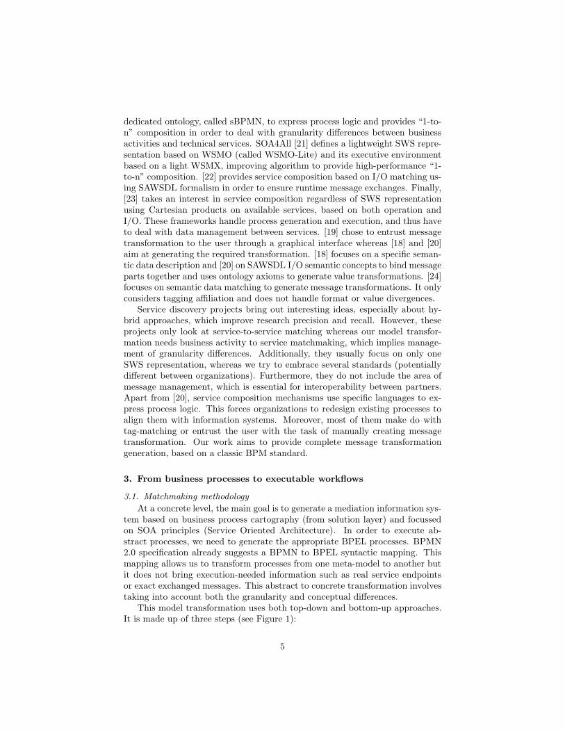
This model transformation uses both top-down and bottom-up approaches.It is made up of three steps (see Figure 1):
5
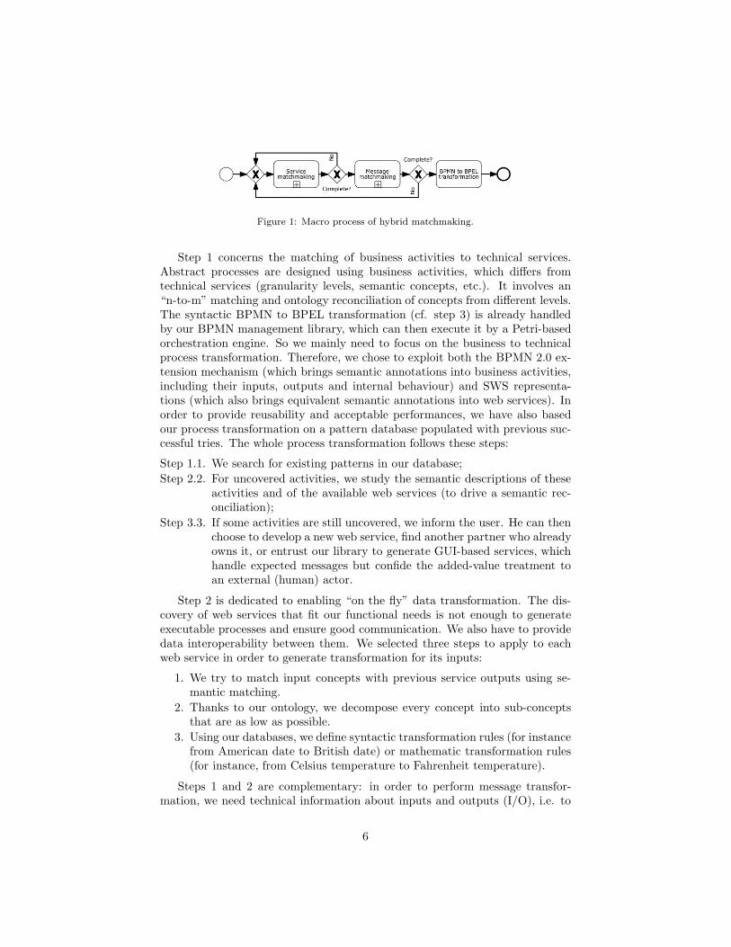
Figure 1: Macro process of hybrid matchmaking.
Step 1 concerns the matching of business activities to technical services.Abstract processes are designed using business activities, which differs fromtechnical services (granularity levels, semantic concepts, etc.). It involves an“n-to-m” matching and ontology reconciliation of concepts from different levels.The syntactic BPMN to BPEL transformation (cf. step 3) is already handledby our BPMN management library, which can then execute it by a Petri-basedorchestration engine. So we mainly need to focus on the business to technicalprocess transformation. Therefore, we chose to exploit both the BPMN 2.0 ex-tension mechanism (which brings semantic annotations into business activities,including their inputs, outputs and internal behaviour) and SWS representa-tions (which also brings equivalent semantic annotations into web services). Inorder to provide reusability and acceptable performances, we have also basedour process transformation on a pattern database populated with previous suc-cessful tries. The whole process transformation follows these steps:
Step 1.1. We search for existing patterns in our database;Step 2.2. For uncovered activities, we study the semantic descriptions of these
activities and of the available web services (to drive a semantic rec-onciliation);
Step 3.3. If some activities are still uncovered, we inform the user. He can thenchoose to develop a new web service, find another partner who alreadyowns it, or entrust our library to generate GUI-based services, whichhandle expected messages but confide the added-value treatment toan external (human) actor.
Step 2 is dedicated to enabling “on the fly” data transformation. The dis-covery of web services that fit our functional needs is not enough to generateexecutable processes and ensure good communication. We also have to providedata interoperability between them. We selected three steps to apply to eachweb service in order to generate transformation for its inputs:
1. We try to match input concepts with previous service outputs using se-mantic matching.
2. Thanks to our ontology, we decompose every concept into sub-conceptsthat are as low as possible.
3. Using our databases, we define syntactic transformation rules (for instancefrom American date to British date) or mathematic transformation rules(for instance, from Celsius temperature to Fahrenheit temperature).
Steps 1 and 2 are complementary: in order to perform message transfor-mation, we need technical information about inputs and outputs (I/O), i.e. to
6
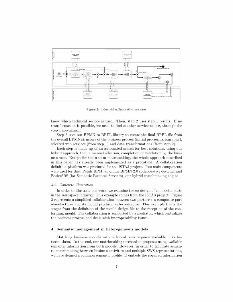
Figure 2: Industrial collaborative use case.
know which technical service is used. Then, step 2 uses step 1 results. If notransformation is possible, we need to find another service to use, through thestep 1 mechanism.
Step 3 uses our BPMN-to-BPEL library to create the final BPEL file fromthe overall BPMN structure of the business process (initial process cartography),selected web services (from step 1) and data transformations (from step 2).
Each step is made up of an automated search for best solutions, using ourhybrid approach, then a manual selection, completion or validation by the busi-ness user. Except for the n-to-m matchmaking, the whole approach describedin this paper has already been implemented as a prototype. A collaborationdefinition platform was produced for the ISTA3 project. Two main componentswere used for this: Petals BPM, an online BPMN 2.0 collaborative designer andEasierSBS (for Semantic Business Services), our hybrid matchmaking engine.
3.2. Concrete illustration
In order to illustrate our work, we examine the co-design of composite partsin the Aerospace industry. This example comes from the ISTA3 project. Figure2 represents a simplified collaboration between two partners: a composite-partmanufacturer and its mould producer sub-contractor. This example treats thestages from the definition of the mould design file to the reception of the con-forming mould. The collaboration is supported by a mediator, which centralizesthe business process and deals with interoperability issues.
4. Semantic management in heterogeneous models
Matching business models with technical ones requires workable links be-tween them. To this end, our matchmaking mechanism proposes using availablesemantic information from both models. However, in order to facilitate seman-tic matchmaking between business activities and multiple SWS representations,we have defined a common semantic profile. It embeds the required information
7

Figure 3: Semantic profile representation.
and is fillable by semantic models (associated to WSDL service descriptions orBPMN 2.0 business process).
4.1. Semantic profile
Before defining a common semantic profile, we need to study our semanticrequirements. This common semantic profile aims to facilitate service matching,and is the matchmaking pivot between business activities and technical services.Therefore, it has to bring enough information to allow our matchmaking engineto differentiate services, and then propose the most appropriate ones.
Firstly, our profile needs to express the functional aspects of models in orderto cover activity requirements and service capabilities. While a simple functionaldescription slot is enough to enable 1-to-1 matchmaking, it could be interest-ing to allow a more detailed description in order to improve engine abilitiessuch as n-to-m matchmaking. Then, our semantic profile embeds an internalbehaviour description, composed of a sequence of unit activities. Each of theseunit activities is represented by a list of semantic concepts, such as functionaldescription.
Secondly, our profile must include high-level semantic description of inputsand outputs. Technical details do not matter for service matchmaking: in-teroperability problems will be solved during message matchmaking, once realservices are chosen, by focusing on XSD annotated schemas or other technicalrepresentations. For instance, if we search for an accounting service, which pro-duces an invoice from a reference to current business, we just search for a webservice that fills our business needs, without needing to consider the businessreference or invoice format.
Figure 3 represents our generic semantic profile. We have defined threedistinct parts: inputs, outputs and operation, which embeds description of itsinternal behaviour. The input and output parts are made up of several seman-tic elements, whereas semantic unit activities compose the internal behaviourdescription. This abstract semantic profile can be easily implemented and ful-filled by most SWS representations, or by the following semantic annotationmechanism for BPMN 2.0.
4.2. Semantic annotation for BPMN: SA-BPMN
Whereas a lot of annotation mechanisms exist for web services, the recentBPMN 2.0 is still devoid of a semantic standard. However, among its usefulfeatures, such as high design range (from very high level processes to executableworkflows), this recent modelling standard brings an XML representation and
8

Figure 4: Semantic annotation for BPMN 2.0 (SA-BPMN).
its extension mechanism. Therefore, we decided to propose our own annotationmechanism, called SA-BPMN 2.0 and based on a previous semantic profile.Figure 4 represents our two new XML tags.
The first element, called SemanticDetails, allows any type of BPMN 2.0task (receive, send, service, user) to be described. It embeds both functionaland internal behaviour description. Each one contains a name and a list of URIs(corresponding to semantic concepts from any ontology).
<Semant i cDeta i l s>(<Funct i ona lDescr ipt i on name= x s : s t r i n g
modelReference= x s : a n y U r i+ >)?(<Interna lBehav ior>
(<Uni tAct iv i ty name= x s : s t r i n gmodelReference= x s : a n y U r i+ />)+
</ i n t e r na lBehav i o r>)?(<xs :any />)∗
</ Semant i cDeta i l s>
The second element, SemanticElements, allows messages and sequencingflows to be described, attaching a list of expected elements. Each element thencontains the syntactic name coupled with a list of concepts.
<SemanticElements>(<SemanticElement name= x s : s t r i n g
modelReference= x s : anyUri+ />)+</SemanticElements>
5. Parametrized hybrid service matchmaking
The proposed service matchmaking approach aims to compare business ac-tivities and technical services. It is based on a 1-to-1 hybrid matchmakingmechanism and focuses on semantic profile comparison. Semantic distance be-tween profiles is performed thanks to a logic-based reasoning coupled with asyntactic similarity measurement. These measurements use main profile parts:operation (service capability or activity requirement) and I/O.
9

5.1. Semantic matchmaking
After extracting the semantic profile of the activity, we first compute thesemantic distance measurement between this profile and available service pro-files. Figure 5 shows the four steps needed to perform this computation for onepotential technical service.
Figure 5: Semantic service matchmaking in details.
Step 1. For each semantic concept involved in the activity profile (noted “Act”in Figure 5), we search for related concepts in available ontologies. Weassociate a rating to each concept, according to its relation to theinitial concepts. We distinguish four types of relations: “exact” forthe initial concept, “equivalent” for close concepts (owl:equivalentClass,owl:equivalentProperties or instances of the same class), “child” for spe-cialized classes or instances and “parent” for generalized concepts. Re-lated concept rate (noted rc) can be cumulated to express more complexrelations:
rc = rcinit,c = maxpossible paths
rP (cinit,c) where rP (ci,cj) =∏
p∈P (ci,cj)
rp.
with cinit and c initial and current concepts, P (ci, cj) a path from cito cj and p a direct relation between two concepts (e.g. a “parent”relationship).
10

For example, if we find a specialized (or child) concept in our ontology,we bring this concept into our related list with a 0.6 grade. In the sameway, if we find a concept two degrees above (e.g. a parent of parent),we will associate the rate 0.09 (0.3 x 0.3). While exact and equivalentconcepts are well rated, child and parent ones are penalized in order toestimate the semantic proximity with the initial concept. If our initialconcept was MouldProduction, a subclass IronMouldProduction may bemore specific whereas the parent concept Production can be too generalfor our research.
Step 2. Then, for each initial concept of search profile, we search for the closestconcept in the target technical service profile (noted “WS” in figure 5).All related concepts were found by the reasoner in the previous step,so this search involves a very simple (and fast) matching. The rateassociated to an initial concept ci for this WS is defined as: rci =maxc∈CActpp∩CWSpp
rc, with pp ∈ {Op, In, Out} the profile part of ci,CActpp and CWSpp
the set of semantic concepts (including inferred ones)involved in the part pp of activity profile (respectively WS profile).For instance, if the target profile contains one concept corresponding toan equivalent concept of the search profile, we associate the rate 0.9. Iftwo target concepts refer to the same search concept, the best rate iskept.
Step 3. Next, we calculate the rates of semantic distance for each profile part(inputs, outputs and operation), considering semantic concept rates andpart coverage. Four cases are taken into account: part coverage is con-sidered as exact if target concepts exactly cover the initial ones, “plugin”if target concepts cover more than expected concepts, “subsume” if anysearch concept is uncovered and “fail” if there is no concept in common.These four cases considered are similar to those of [12], although thecoverage computation and the treatment are different. The penalty ap-plied differs as a function of the studied part. A small penalty is appliedfor operation and output in the case of “plugin” coverage, a bigger oneis used in “subsume” whereas the opposite rule applies to input parts.For output or operation, a “plugin” coverage means the target serviceprovides more functionalities or results than expected whereas “sub-sume” indicate a lack of functionality. For input, “plugin” means someunsolicited information is expected whereas “subsume” indicate thatless information is needed. Algorithm 1 aims at evaluating the cover-age of an element tree, returning true if an element or all its children(recursively) are semantically linked (relem = 0), and false otherwise. Ifthis function returns false when applied to the expected root element(from expected activity), it means we are in a “subsume” case, whereasif it returns false when applied to the target root element (from webservice), we are in a “plugin” case.Whereas the final rating of the operation is computed thanks to a simplearithmetic average (rOp = 1
|COp|
∑
c∈COprc, with COp the set of seman-
tic concepts attached to the operation), the rating of the input or output
11

Algorithm 1 isCoverageAcceptablefunction isCoverageAcceptable(element, coverageMap)
return isCoverageAcceptable(element, coverageMap, new List)end function
◃ This second function is never called directly but avoids infinite loops due to recursive elementsfunction isCoverageAcceptable(element, coverageMap, studiedList)
if element.rate in coverageMap = 0 then
return trueelse
if element.children = ∅ AND element /∈ studiedList then
Add element to studiedListfor all element.children as child do
if ¬ isCoverageAcceptable(element, coverageMap, studiedList) then
return falseend if
end for
return trueend if
return falseend if
end function
part must take into consideration element hierarchy and semantic cov-erage. In this view, the final rating of input (or output) is computedas a recursive arithmetic average, to which we apply a coverage loadedpremium:
rIn = PIn ∗ re(rootIn)
where PIn =
⎧
⎪
⎪
⎨
⎪
⎪
⎩
Psubsume if “subsume”Pplugin if “plugin”Psubsume ∗ Pplugin if both1 otherwise
and re(elem) = max(1
|Celem|
∑
c∈Celem
rc,1
|Chelem|
∑
child∈Chelem
re(child))
with PIn the penalty applied to this input, rootIn the root element ofinput, Celem the set of semantic concepts associated to element elemand Chelem the set of elem’s children.
Step 4. Lastly, the final semantic rating is computed by applying an importanceweighting between the three rates (inputs, outputs, operation):
rWS = wOp ∗ rOp + (1− wOp) ∗ rI/O
where rI/O =
{
rIn+rOut
2 if activity has output(s)rrIn otherwise
with wOp ∈ [0; 1] the importance weighting of the operation.
Of course, steps 2 to 4 are computed for each technical service profile inorder to obtain a semantic distance measurement for each available service.A semantic threshold can be defined by the user to automatically eliminate
12
irrelevant services before the next step then lighten the syntactic matchmakingcomputation.
As stated above, all weights and penalties can be changed between compu-tations by the user according to IS and ontology specificities.
5.2. Syntactic matchmaking
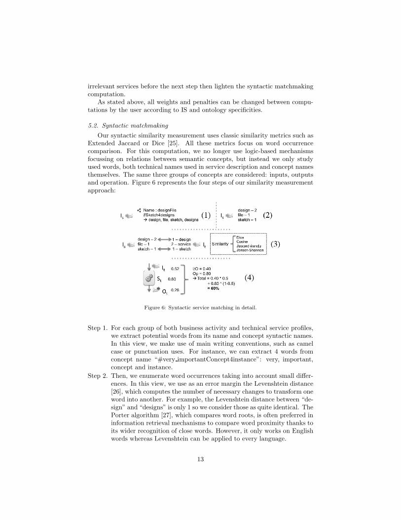
Our syntactic similarity measurement uses classic similarity metrics such asExtended Jaccard or Dice [25]. All these metrics focus on word occurrencecomparison. For this computation, we no longer use logic-based mechanismsfocussing on relations between semantic concepts, but instead we only studyused words, both technical names used in service description and concept namesthemselves. The same three groups of concepts are considered: inputs, outputsand operation. Figure 6 represents the four steps of our similarity measurementapproach:
Figure 6: Syntactic service matching in detail.
Step 1. For each group of both business activity and technical service profiles,we extract potential words from its name and concept syntactic names.In this view, we make use of main writing conventions, such as camelcase or punctuation uses. For instance, we can extract 4 words fromconcept name “#very importantConcept4instance”: very, important,concept and instance.
Step 2. Then, we enumerate word occurrences taking into account small differ-ences. In this view, we use as an error margin the Levenshtein distance[26], which computes the number of necessary changes to transform oneword into another. For example, the Levenshtein distance between “de-sign” and “designs” is only 1 so we consider those as quite identical. ThePorter algorithm [27], which compares word roots, is often preferred ininformation retrieval mechanisms to compare word proximity thanks toits wider recognition of close words. However, it only works on Englishwords whereas Levenshtein can be applied to every language.
13
Step 3. Thanks to similarity metrics, we can then measure the distance betweengroups of words. Several similarity measurement techniques exist andwe implemented four of them: Cosine, Dice, Extended Jaccard andJensen-Shannon. However, large-scale syntactic matchmaking showssimilar results for these four metrics. By default, we chose Dice similar-ity measurement, which is slightly faster than the others. This compu-tation returns a proximity rate, between 0 and 1, for each profile part:simDice
pp = 2|A·B||A|2+|B|2 , with A and B the normalized vectors for the activ-
ity profile part and target web service, containing occurrence numbersof each word that appears in one or the other (enumerated during theprevious step).
Step 4. Finally, once the three groups have been rated for a specific technicalservice (input, output and operation), we can compute its final mark aswe did for semantic distance, using the same importance weighting.
Whereas the first two steps can be performed once for the search profile,others must be done for each potential target service (according to semanticmatchmaking). Another threshold mechanism allows our matchmaking engineto automatically exclude irrelevant services before sending results to the user.
Next, we combine the two previous ratings using an importance weighting ofthe logic-based computed mark compared to the syntactic one, to obtain a finaldistance rate: rfinal = wlogic ∗ rlogic + (1 − wlogic) ∗ rsyntact, with wlogic ∈ [0; 1]the importance weighting of the semantic, rlogic and rsyntact the semantic andsyntactic ratings. Finally, results are sent to the user who can choose the mostappropriate technical services from among only a few relevant services ratherthan the thousands of available ones.
5.3. Evaluation of performance
In order to evaluate our service matchmaking engine performances, we usedthe SAWSDL test collection SAWSDL-TC21. This test suite contains 42 queriesand their expected responses over 1080 services and 38 ontologies. It allows usto conduct a retrieval performance evaluation on a large base of semanticallyannotated service descriptions covering several application domains, such astravel, education, food or medical care. Even if these SAWSDL only containsemantic annotations on a I/O schema description, it remains the best way totest a service matchmaking engine while there is currently no other test collec-tion as complete as this one available. The performance tests were performedon a machine with 2Ghz i7 CPU and 2Go RAM on Mac OS X and Java 6.
All performance measurements are based on two classic retrieval informationindicators: precision and recall (noted P and R in the following equations). Theprecision indicator represents the quality of results (percentage of relevant doc-uments among retrieved ones) whereas the recall indicator shows the sufficiencyof the result (percentage of retrieved documents among relevant ones). From
1http://semwebcentral.org/projects/sawsdl-tc/
14
these two indicators, we calculated the average Fmeasure for all queries and theMean-Average Precision (MAP ):
Fmeasure = 2 ·P · R
P +R
where P =|retrieved ∩ relevant|
|retrieved|and R =
|retrieved ∩ relevant|
|relevant|
MAP =
∑Qq=1 AP (q)
Qwhere AP =
∑nk=1 P (k) ·Rel(k)
|relevant|
where AP (q) is the average precision for the query q, Q is the number ofqueries, P (k) represents the precision for the first k results (from the orderedretrieved documents) and Rel(k) is equal to 1 if the kth document is relevant,0 otherwise. While Fmeasure combines recall and precision for a whole queryresult, MAP represents precision evolution along ordered results. Finally, wedepicted the precision/recall graph, representing the evolution of precision func-tions of recall, computed from precision and recall values for each kth first re-trieved documents of each query result.
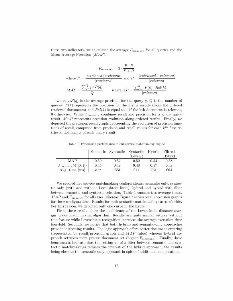
Table 1: Evaluation performance of our service matchmaking engine
Semantic Syntactic Syntactic Hybrid Filtred(Leven.) Hybrid
MAP 0.59 0.52 0.52 0.54 0.58Fmeasure(∈ [0; 1]) 0.45 0.48 0.48 0.57 0.48Avg. time (ms) 512 283 971 751 664
We studied five service matchmaking configurations: semantic only, syntac-tic only (with and without Levenshtein limit), hybrid and hybrid with filterbetween semantic and syntactic selection. Table 1 summarizes average times,MAP and Fmeasure for all cases, whereas Figure 7 shows recall/precision graphsfor these configurations. Results for both syntactic matchmaking cases coincide.For this reason, we depicted only one curve in the figure.
First, these results show the inefficiency of the Levenshtein distance mar-gin in our matchmaking algorithm. Results are quite similar with or withoutthis feature while Levenshtein recognition increases the average execution timefour-fold. Secondly, we notice that both hybrid- and semantic-only approachesprovide interesting results. The logic approach offers better document ordering(represented by recall/precision graph and MAP value) whereas hybrid ap-proach retrieves more precise document set (higher Fmeasure). Finally, thesebenchmarks indicate that the setting-up of a filter between semantic and syn-tactic matchmakings reduces the interest of the hybrid approach, the resultsbeing close to the semantic-only approach in spite of additional computation.
15

Figure 7: Service matchmaking performance results.
According to these benchmark results, the advantages of a hybrid approachappear limited. However, it should be remembered that SAWSDL-TC onlycontains fully annotated service descriptions, which cannot be the case in realindustrial situations.
5.4. The quest for process reconciliation
Thanks to internal behaviour descriptions coupled with the previous hybridmechanism, it became possible to create semantic profiles of atomic functionsin order to match them. These profiles are only partially filled because of lackof internal information descriptions but they still provide some mapping trailsthat we can confirm using available inputs/outputs description. Unfortunately,this approach involves a combinatorial computation. For each possible group ofactivities, we theoretically have to test each possible group of technical services.In order to limit possible associations, we considered some simple filters:
• Some information about collaboration, such as target partner, activitydomain and non-functional requirements are provided by both businessprocess and service descriptions and can be used as filters. These filtersdo not require time-consuming computation and can be performed beforeour hybrid matchmaking while this information is contained in our tech-nical registry. For instance, if the collaboration involves one preselectedmould producer and the business process specifies the need to use securedexchanges, we can perform matchmaking that only considers secured ser-vices from this particular service provider.
• We cannot consider bringing together activities that are randomly se-lected. The process logic can also reduce possible groups. Any businessprocess implies connections between activities that we cannot avoid (i.e.
16

sequences, gateways). Figure 8 illustrates possible logic groups of busi-ness activities that can be considered for semantic reconciliation. Frommillions of possible groups, there are only 22 useable groups.
Figure 8: Process logic study for combinatorial computation reduction.
For now, this n-to-mmatchmaking remains very simple. Implementation andtests are in progress and the list of possible improvements is still lengthening.Some recent external research, such as [28] is contributing promising new ideasfor improving the precision of this approach, and we are still working on theseimprovements too.
6. Ensuring message interoperability
Once the user has selected technical services, we can focus on real data map-ping. The discovery of web services that fit our functional needs is not enough togenerate executable processes and ensure good communication between partner’ISs. We also have to provide interoperability between these services.
6.1. Technical databases
Each service invocation needs a specific input message to be correctly exe-cuted. Expected tags are described in the service description (name, data type)but they must be filled with relevant data in exact format. They usually dontbring information, but organise it. Furthermore, service descriptions can onlydepict standard data types. For expected input described as a simple string,the real service can expect a date in an exotic format but service descriptionsare not precise enough to express it.
Semantic business information is not sufficient for message matchmaking.One business concept such as delivery date can be expressed in many formats(XML Datetime, US date format). This choice belongs to the service devel-oper who can also use classic XML Datetime, declared as such in the servicedescription, or choose to use an exotic one, declared as a simple string. In orderto solve this problem, we propose a technical ontology focused on format con-cepts and linked to three technical databases filled with syntax representationand conversion formulae. The factorization database expresses possible decom-positions using concept URIs as value representations. For instance, using the
17
three decomposition examples below, we can factorize a complex concept such asXsDatetime into unit concepts and its embedded syntax (#XsYear-#XsMonth-#XsDayT#XsHour:#XsMinute:#XsSecond).
#XsDatetime = %%#XsDate%%T%%#XsTime%%#XsDate = %%#XsYear%%−%%#XsMonth%%−%%#XsDay%%#DateUs = %%#XsMonth%%−%%#XsDay%%−%%#XsYear%%
The formula database is close to the previous one, except that it expressesconversion formulae between two technical concepts. Here is an example ofconversion between millimetre and inch measurements:
#Mil imeter = %%#Inch%% ∗ 25 .4
Finally, the regex database links those technical concepts to their regularexpressions (e.g. #XsYear = [0-9]4). This technical information will allow ourtransformation engine to treat real values in run time. Those technical conceptscan then be used to annotate input/output descriptions in order to support ourtransformation generation mechanism.
6.2. Message matchmaking approach
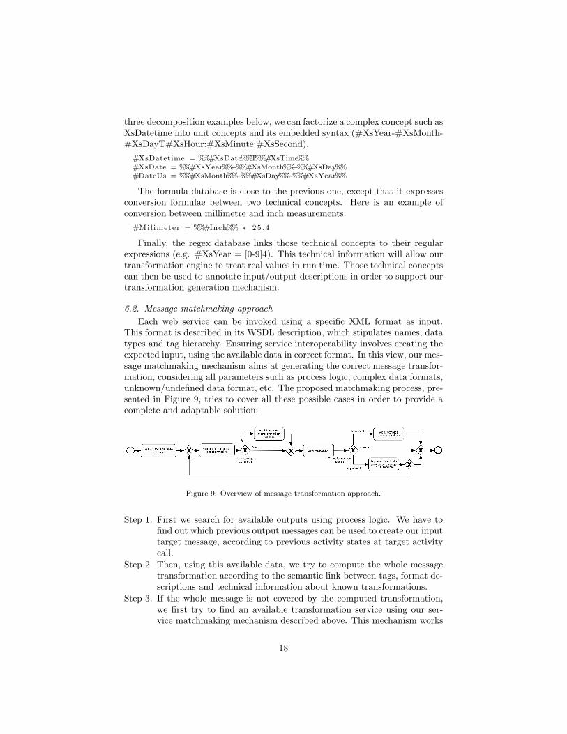
Each web service can be invoked using a specific XML format as input.This format is described in its WSDL description, which stipulates names, datatypes and tag hierarchy. Ensuring service interoperability involves creating theexpected input, using the available data in correct format. In this view, our mes-sage matchmaking mechanism aims at generating the correct message transfor-mation, considering all parameters such as process logic, complex data formats,unknown/undefined data format, etc. The proposed matchmaking process, pre-sented in Figure 9, tries to cover all these possible cases in order to provide acomplete and adaptable solution:
Figure 9: Overview of message transformation approach.
Step 1. First we search for available outputs using process logic. We have tofind out which previous output messages can be used to create our inputtarget message, according to previous activity states at target activitycall.
Step 2. Then, using this available data, we try to compute the whole messagetransformation according to the semantic link between tags, format de-scriptions and technical information about known transformations.
Step 3. If the whole message is not covered by the computed transformation,we first try to find an available transformation service using our ser-vice matchmaking mechanism described above. This mechanism works
18
well for simple messages, but is limited for really complex informationsuch as CAD formalisms where thousands of tags are involved. How-ever, this kind of business transformation is usually performed by highvalue-added services provided by software editors themselves (e.g. filetransformation between two major versions of a specified software).
Step 4. Result transformation is submitted to the user for validation or com-pletion. Three cases are then possible:
• Computed transformation is correct and covers the whole inputmessage. In this case, the user can directly validate it. The trans-formation is generated in computer-readable language then addedinto the workflow description.
• The transformation is feasible using data from the previous servicebut is incorrect or incomplete for now. In this case, the user canmanually complete or correct the transformation. The technicaldatabase is then updated and this new information will then beuseable for future transformations.
• Transformation is impossible according to available information.The user can then choose to (i) try with another possible service(result from service matchmaking), (ii) search for a new partnerwho proposes expected service or (iii) generate a business service, asimple user interface, which allows the user to bring in the missinginformation. In every instance, the chosen service needs a ded-icated message transformation. The whole generation process isthen resumed from transformation computation.
The following part details steps (1) and (2) of this generation process, whichconcentrate the majority of our added value. First, we look at the selection ofavailable messages based on process logic study, then the computation of thetransformation file.
6.3. Selection of available messages
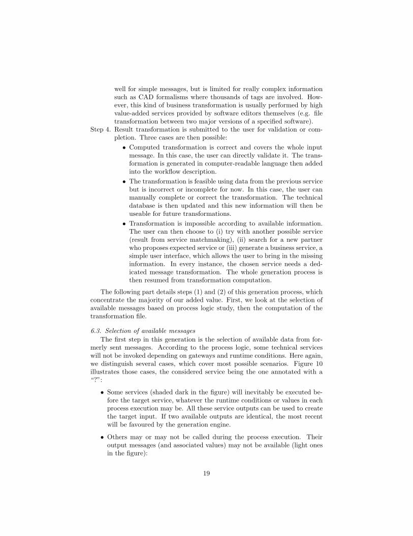
The first step in this generation is the selection of available data from for-merly sent messages. According to the process logic, some technical serviceswill not be invoked depending on gateways and runtime conditions. Here again,we distinguish several cases, which cover most possible scenarios. Figure 10illustrates those cases, the considered service being the one annotated with a“?”:
• Some services (shaded dark in the figure) will inevitably be executed be-fore the target service, whatever the runtime conditions or values in eachprocess execution may be. All these service outputs can be used to createthe target input. If two available outputs are identical, the most recentwill be favoured by the generation engine.
• Others may or may not be called during the process execution. Theiroutput messages (and associated values) may not be available (light onesin the figure):
19
Figure 10: Selection of available messages.
– Services from prior conditional branches: their outputs can be con-sidered only if all process branches share the same semantic concepts,i.e. produce the same data (possibly with different values). Hybridmatchmaking is then performed in order to compare available out-puts. If a transformation can be computed by our engine, a newvariable is created in the process description in order to store theruntime value in a common format. This variable will be filled atall process executions and can then can be used to create the targetinput.
– Services placed downstream from our target service but within a com-mon loop: their outputs are not available at the first call but can beused if the way back is used to update previous values. The mech-anism is quite similar to the previous one: hybrid matchmaking isperformed to determine which data can be updated by the concernedservices and the workflow description is consequently modified.
• Finally, remaining services (the white ones in the figure) cannot be calledat all before the target service. These outputs are simply excluded fromconsidered data.
Once all available output has been selected, with associated ratings depend-ing on their distance from the target service, we can begin the transformationcomputation (Step 2).
20
6.4. Generation mechanism
In our specified environment, and according to the low coupling principle,all exchanged messages are written in XML. Few methods focus on XML trans-formations, but one of them has broken away from the others thanks to itsmaturity and flexibility: XSLT (for Extensible Stylesheet Language Transfor-mations). This mechanism aims at generating accurate XSLT transformationfor each service using previously selected available messages and their semanticannotations.
Service I/O are described into XML Schema formalism embedded in WSDLfiles. This format description is limited to standardized data types and all ex-otic formats are only specified as simple string. Unfortunately, added semanticinformation is not sufficient to overcome the lack of format description. Onebusiness concept such as delivery date can be expressed in many formats (XMLDatetime, US date format), according to the service developers choice. In orderto solve this problem, we propose a technical ontology focused on format con-cepts and linked to a technical database filled with syntax representation andconversion formulae. This database contains the following tables.
• The factorization table details possible concept decompositions using URIsas value representation. For example, a complex concept such as #Xs-Datetime (in XML format) can be factorized into unit concepts as #XsYear-#XsMonth-#XsDayT#XsHour:#XsMinute:#XsSecond.
• The formula table, which expresses conversion formulae between two tech-nical concepts. For instance, conversion between millimetre and inch mea-surements (#Millimetre = #Inch x 25.4).
• Finally, the regular expression table links those technical concepts to theirsyntactic description (e.g. #XsYear = [0-9]{4} means the year is writtenwith 4 digits). This technical information will allow our transformationengine to treat real values at runtime.
The following generation mechanism is based on both XML schema syntacticdescription and its annotated technical concepts. The generation mechanismcan be split into three steps (see Figure 11):
Step 2.1. First, thanks to our hybrid matchmaking engine and list of availabledata (see section 6.3), we match target tag concepts with availablesource concepts. This enables us to find equivalent tags, withoutconsidering data format for the moment. For instance, the selectedservice expects, among others, a date in a XML Datetime format anda length in millimetres. Thanks to the hybrid matchmaking engine,we find some close potential tags from selected outputs: Date (USformat) and Time that cover the Datetime embedded concepts andLengthInch, which corresponds to the expected length expressed ininches.
21

Figure 11: Generation of XPath functions.
Step 2.2. Next, once previous values fitting our functional needs have been se-lected, we can focus on the data and format matching, using the tech-nical description of formats from our databases (described above), wecan now deduce the XPath function, which allows us to transformavailable values into expected ones. To this end, we first factorizeboth available and expected concepts into finest-grained concepts inorder to compare concepts of similar granularity. We then try tomatch target unit concepts with previous output concepts, generatingthe corresponding XPath function.As you can see in Algorithm 2 (in Annexe Appendix A, an example isgiven in the comments on XsDatetime generation from Date US andXsTime), we first use the factorization database to decompose theexpected value description into unit concepts (L4). For each potentialvalue we also decompose it into unit technical concepts in order tomatch concepts of the same granularity (L12). If one concept fromthis potential value corresponds to an expected unit concept, we re-place this concept in its decomposition with its regular expression andassociate the expected concept to a unique key (needed for final XPathreplacement, L16-22). Once all potential concepts have been treated,we search for uncovered expected concepts in order to find a formulaconversion (L30-33). If we find one for each uncovered concept, wecan generate the XPath transformation using collected information(used potential values, their regular expression and associated key or
22
formula). ). Thus, this algorithm produces a general XPath formulato create an expected value from previously available values (L39-57).In real implementation, ids of potential values correspond to the realvalue path in the message and concepts are referred to by their com-plete URIs. Incidentally, the “searchFormula” method is not detailedhere, but it simply checks coverage of concepts in formulas with po-tential concepts.
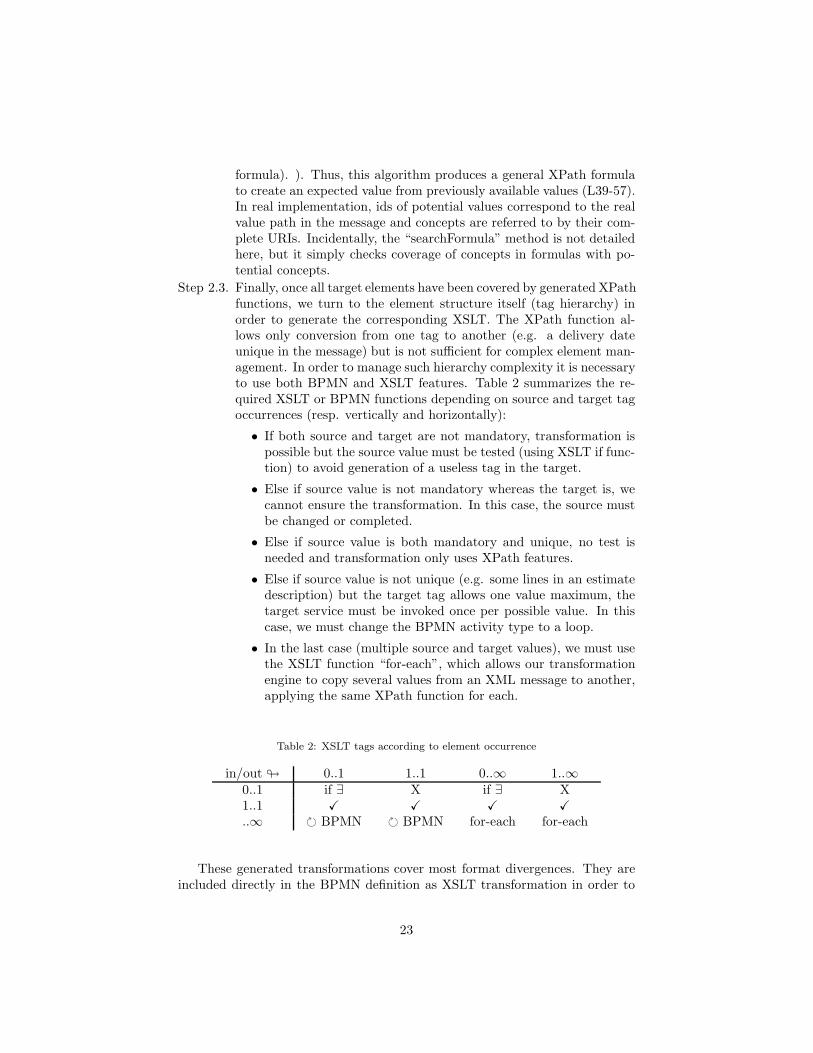
Step 2.3. Finally, once all target elements have been covered by generated XPathfunctions, we turn to the element structure itself (tag hierarchy) inorder to generate the corresponding XSLT. The XPath function al-lows only conversion from one tag to another (e.g. a delivery dateunique in the message) but is not sufficient for complex element man-agement. In order to manage such hierarchy complexity it is necessaryto use both BPMN and XSLT features. Table 2 summarizes the re-quired XSLT or BPMN functions depending on source and target tagoccurrences (resp. vertically and horizontally):
• If both source and target are not mandatory, transformation ispossible but the source value must be tested (using XSLT if func-tion) to avoid generation of a useless tag in the target.
• Else if source value is not mandatory whereas the target is, wecannot ensure the transformation. In this case, the source mustbe changed or completed.
• Else if source value is both mandatory and unique, no test isneeded and transformation only uses XPath features.
• Else if source value is not unique (e.g. some lines in an estimatedescription) but the target tag allows one value maximum, thetarget service must be invoked once per possible value. In thiscase, we must change the BPMN activity type to a loop.
• In the last case (multiple source and target values), we must usethe XSLT function “for-each”, which allows our transformationengine to copy several values from an XML message to another,applying the same XPath function for each.
Table 2: XSLT tags according to element occurrence
in/out ! 0..1 1..1 0..∞ 1..∞0..1 if ∃ X if ∃ X1..1 " " " "
..∞ # BPMN # BPMN for-each for-each
These generated transformations cover most format divergences. They areincluded directly in the BPMN definition as XSLT transformation in order to
23
be exported as external services during the BPMN to BPEL automated trans-formation. If this transformation is not complete after this computation, themessage-matchmaking process continues as described in section 6.2.
7. Perspectives and conclusion
Driving a BPM approach is a very common solution to improve the maturityof organizations and enterprises. Such an approach is usually dedicated to (i)obtaining a certification, (ii) diagnosis of some dysfunctions and improvement ofthe overall behaviour or (iii) providing requirements to improve the IS. However,concerning point (iii), there is still a large gap between the business considera-tions regarding the obtained process cartography and the technical world of ISdeployment. This work aims to fill that gap with tangible theoretical mecha-nisms and efficient software tools. To this end, we propose a complete and fullyimplemented methodology, based on SWS features, which covers transforma-tion from business process cartography to executable workflows. The semanticissues, described in [29] are addressed on the three required consideration levels(information, functions, processes). The most important perspectives mainlyconcern the use of non-functional requirements (and governance issues) in thereconciliation mechanism in order to enlarge the considered criteria during theselection phase. Elements such as latency, security or efficiency requirementsmay be embedded in business process models in order to be taken into accountduring the semantic reconciliation step (this step might thus be refined andimproved). Documentation and source code of these research components isavailable at: http://research.petalslink.com. For any information about otherproducts such as Petals ESB and EasyBPEL, our orchestration engine, pleasevisit: http://docs.petalslink.com.
References
[1] F. Benaben, W. Mu, S. Truptil, H. Pingaud, J. Lorre, Information systemsdesign for emerging ecosystems, in: Digital Ecosystems and Technologies(DEST), 2010 4th IEEE International Conference on, 2010, pp. 310–315.
[2] F. Benaben, N. Boissel-Dallier, J. P. Lorre, H. Pingaud, Semantic recon-ciliation in interoperability management through Model-Driven approach,in: Collaborative Networks for a Sustainable World, 2010, pp. 705–712.
[3] V. Rajsiri, Knowledge-based system for collaborative process specification,Thse en systmes industriels, INPT - EMAC (2009).
[4] J. Touzi, F. Benaben, H. Pingaud, J. P. Lorre, A model-driven approachfor collaborative service-oriented architecture design, International Journalof Production Economics 121 (1) (2009) 5–20.
[5] S. Truptil, Etude de l’approche de l’interoprabilit par mdiation dans lecadre d’une dynamique de collaboration applique la gestion de crise, Ph.D.thesis, INPT - EMAC, Albi (2011).
24
[6] T. Malone, K. Crowston, G. Herman, Organizing business knowledge: theMIT process handbook, the MIT Press, 2003.
[7] W. Mu, F. Benaben, H. Pingaud, N. Boissel-Dallier, J. Lorre, A model-driven BPM approach for SOA mediation information system design in acollaborative context, in: Services Computing (SCC), 2011 IEEE Interna-tional Conference on, 2011, pp. 747–748.
[8] H. Hoang, P.-C. Tran, T. Le, State of the art of semantic business processmanagement: An investigation on approaches for business-to-business in-tegration, in: N. Nguyen, M. Le, J. Swiatek (Eds.), Intelligent Informationand Database Systems, Vol. 5991 of Lecture Notes in Computer Science,Springer Berlin / Heidelberg, 2010, pp. 154–165.
[9] N. Boissel-Dallier, F. Bnaben, H. Pingaud, Model-driven engineering ofmediation information system: application to the ISTA3 use-case, in: Pro-ceedings of the sixth international conference of I-ESA, Springer, Valencia,Spain, 2012.
[10] A.-M. Barthe, M. Lauras, F. Bnaben, 8th international conference on infor-mation systems for crisis response and management : From early-warningsystems to preparedness and training, in: Proceedings of the 8th Interna-tional Conference on Information Systems for Crisis Response and Man-agement (ISCRAM), Lisbon, 2011.
[11] G. Mac Ramte, F. Bnaben, J. Lamothe, Towards an agile informationdecision support system in transport crisis context, in: Proceedings of theI-ESA conference, Valencia Spain, Springer, Valencia, Spain, 2012.
[12] M. Klusch, P. Kapahnke, I. Zinnikus, Sawsdl-mx2: A machine-learningapproach for integrating semantic web service matchmaking variants, in:Web Services, 2009. ICWS 2009. IEEE International Conference on, 2009,pp. 335–342.
[13] K. Sivashanmugam, J. A. Miller, A. P. Sheth, K. Verma, Framework for se-mantic web process composition, International Journal of Electronic Com-merce 9 (2) (2005) 71–106.
[14] S. Alexakis, M. Bauer, A. Pace, A. Schumacher, A. Friesen, A. Bouras,D. Kourtesis, Application of the fusion approach for assisted compositionof web services, Establishing The Foundation Of Collaborative Networks(2007) 531–538.
[15] M. Klusch, B. Fries, K. Sycara, Automated semantic web service discoverywith OWLS-MX, in: Proceedings of the fifth international joint conferenceon Autonomous agents and multiagent systems, 2006, pp. 915–922.
[16] F. Kaufer, M. Klusch, Wsmo-mx: A logic programming based hybrid ser-vice matchmaker, in: Web Services, 2006. ECOWS’06. 4th European Con-ference on, 2006, pp. 161–170.
25
[17] Y. Chabeb, S. Tata, A. Ozanne, Yasa-m: A semantic web service match-maker, in: Advanced Information Networking and Applications (AINA),2010 24th IEEE International Conference on, 2010, pp. 966–973.
[18] F. Facca, S. Komazec, I. Toma, WSMX 1.0: A further step toward a com-plete semantic execution environment, The Semantic Web: Research andApplications (2009) 826–830.
[19] J. Domingue, L. Cabral, S. Galizia, V. Tanasescu, A. Gugliotta, B. Norton,C. Pedrinaci, IRS-III: a broker-based approach to semantic web services,Web Semantics: Science, Services and Agents on the World Wide Web 6 (2)(2008) 109–132.
[20] M. Hepp, F. Leymann, J. Domingue, A. Wahler, D. Fensel, Semantic busi-ness process management: A vision towards using semantic web servicesfor business process management, in: IEEE International Conference one-Business Engineering, 2005. ICEBE 2005, 2005, pp. 535–540.
[21] F. Lecue, Y. Gorronogoitia, R. Gonzalez, M. Radzimski, M. Villa, SOA4All:an innovative integrated approach to services composition, in: Web Services(ICWS), 2010 IEEE International Conference on, 2010, pp. 58–67.
[22] F. Ishikawa, S. Katafuchi, F. Wagner, Y. Fukazawa, S. Honiden, Bridgingthe gap between semantic web service composition and common implemen-tation architectures, in: Services Computing (SCC), 2011 IEEE Interna-tional Conference on, 2011, pp. 152–159.
[23] N. Guermouche, O. Perrin, C. Ringeissen, A mediator based approach forservices composition, in: Sixth International Conference on Software Engi-neering Research, Management and Applications, 2008. SERA ’08, IEEE,2008, pp. 273–280. doi:10.1109/SERA.2008.43.
[24] D. Gagne, M. Sabbouh, S. Bennett, S. Powers, Using data semantics toenable automatic composition of web services, in: Services Computing,2006. SCC’06. IEEE International Conference on, 2006, pp. 438–444.
[25] W. Cohen, P. Ravikumar, S. Fienberg, A comparison of string metrics formatching names and records, in: KDD Workshop on Data Cleaning andObject Consolidation, Vol. 3, 2003.
[26] V. Levenshtein, Binary codes capable of correcting deletions, insertions,and reversals, in: Soviet Physics Doklady, Vol. 10, 1966, pp. 707–710.
[27] M. Porter, An algorithm for suffix stripping, Program: electronic libraryand information systems 14 (3) (1980) 130–137.
[28] C. Gerth, M. Luckey, J. Kuster, G. Engels, Precise mappings betweenbusiness process models in versioning scenarios, in: Services Computing(SCC), 2011 IEEE International Conference on, pp. 218–225.
26

[29] F. Benaben, N. Boissel-Dallier, H. Pingaud, J.-P. Lorre, Semanticissues in model-driven management of information system interoper-ability, International Journal of Computer Integrated Manufacturing(IJCIM)doi:10.1080/0951192X.2012.684712.
27

Appendix A. XPath generation algorithm
28

Algorithm 2 generateXPathfunction generateXPath(targetSyntax, potentialSyntaxList)
◃ targetSyntax: %%#XsDatetime%%◃ potentialSyntaxList: $id1=%%#DateUs%%; $id2=%%#XsTime%%
targetSyntax.factorize()5: ◃ targetValue: %%#XsYear%%-%%#XsMonth%%-
%%#XsDay%%T%%#XsHour%%:%%#XsMinute%%:%%#XsSecond%%for all targetSyntax.concepts as targetConcept do
Add targetConcept in coverageMapcoverageMap.targetConcept.value ← 0
end for
10: key ← 1for all potentialSyntaxList.elements as potentialSyntax do
potentialSyntax.factorize()◃ $id1 = %%#XsMonth%%-%%#XsDay%%-%%#XsYear%%
for all potentialSyntax.concepts as potentialConcept do
15: ◃ #XsMonthif potentialConcept ∈ coverageMap then
Replace potentialConcept with ”(” + potentialConcept.regExp + ”)” inpotentialSyntax
◃ $id1 = ([0-9]2)-%%#XsDay%%-%%#XsYear%%coverageMap.potentialConcept.value ← ”$” + key
20: ◃ #XsMonth = $id1key ← key + 1Add potentialSyntax to usedPotentialSyntax
else
Replace potentialConcept with potentialConcept.regExp in potentialSyntax25: end if
end for
◃ $id1([0-9]2)-([0-9]2)-([0-9]4)end for
for all coverageMap.targetConcepts as targetConcept do
30: if coverageMap.targetConcept.value = 0 then ◃ 0 = uncovered conceptformula← searchFormula(potentialSyntaxList,usedPotentialSyntax)if formula = null then
coverageMap.targetConcept.value ← formulaelse ◃ Concept still uncovered
35: return nullend if
end if
end for
if usedPotentialSyntax.size > 1 then
40: source← ”fn:string-join(”end if
for all usedPotentialSyntax.elements as potentialSyntax do
source← source+ potentialSyntaxList.potentialSyntax.id + ”,”pattern← pattern + potentialSyntaxList.potentialSyntax.value + ” ”
45: end for
Replace last ”,” with ”” in sourcesource← source+ ”’ ’)”Replace last ” ” with ”” in pattern
◃ source: fn:string-join ($id1, $id2,’ ’)50: ◃ pattern: ([0-9]2):([0-9]2):([0-9]2) ([0-9]4)-([0-9]2)-([0-9]2)
for all coverageMap.targetConcepts as targetConcept do
Replace targetConcept with key in targetSyntaxend for
◃ targetSyntax = ($4)-($5)-($6)T($1):($3):($2)55: xpath← ”fn:replace(” + source + ”,” + pattern + ”,” + targetSyntax + ”);”
◃ fn:replace(fn:string-join ($id1,$id2,’ ’),([0-9]2):([0-9]2):([0-9]2) ([0-9]4)-([0-9]2)-([0-9]2),($4)-($5)-($6)T($1):($3):($2));
return xpathend function
29