Mediatek Pump Express Introductioncdn-cw.mediatek.com/Features/Pump Express Series...
30
2016 Mediatek Pump Express Introduction
-
Upload
truonglien -
Category
Documents
-
view
227 -
download
3
Transcript of Mediatek Pump Express Introductioncdn-cw.mediatek.com/Features/Pump Express Series...

2016
Mediatek Pump Express Introduction

Outline
Pump Express Evolution
PE+ / PE+2.0
PE3.0
PE3.0 Q&A

Pump Express Plus Evolution
3

Pump Express Evolution 2014 2015 2016 2017
Q3 Q4 Q1 Q2 Q3 Q4 Q1 Q2 Q3 Q4 Q1 Q2
Efficiency
Ch
arg
e C
urre
nt
o 3A Single Charge o 4.5A Master/Slave Charge o Ƞ = 90% o Unidirectional Vbus communication
75% in 35min
o 3A Single Charger o 4.5A Master/Slave Charger o Ƞ = 92% o Unidirectional Vbus Communication
75% in 30min
o 5A+ Direct Charge o Ƞ= 95%+ o Bidirectional Type-C VDM Communication o 20+ Protection Schemes
3.0
75% in 20min
5/7/9/12V 5~20V, 0.5V/step
3~6V, CC/CV
Note1 : The adaptor of PE3.0 is capable of outputting CC (Constant Current) & CV (Constant Voltage) with fine resolution. Note2 : PE+2.0 & PE3.0 will co-exist in the market. PE+2.0 – for micro-B/type-C connector & lower cost PE3.0 – for type-C connector & higher charge current

Communication Protocols
MediaTek PE+ PE+2.0 PE+3.0 (Direct Charge)
MP Schedule Now Now Q3’16
TA Output 5V~12V
(Fixed 5/7/9/12V) 5V~20V
(0.5V per step) 3V~6V
(10-20mV per step)
Communication VBUS current modulation VBUS current modulation USB PD
Charge Current Single 3A/Parallel 4.5A Single 3A/Parallel 4.5A+ Direct Charge 5A+
Efficiency 90% 92% 95%+
Competitor’s Counter Tech
QC2.0 QC3.0 N/A

PE+ / PE+2.0
6

PE+2.0 Improvements
-7-
Item Feature Description
1 Faster communication Reduce TA identification time from 2.1sec to 0.9s
2 Fine-grain voltage levels -5V-to-20V (step = 0.5V) -0.5V/step is good enough
Adjust adaptor voltage dynamically to optimize charging efficiency
3 Cable Impedance Measurement (Safety & Eff. Opt.)
Calculate cable impedance and manage charging behavior accordingly

State Machine
-8- P34
12.5V
20V
5V
WDT*0 time out
5.5V 6V 6.5V
19.5V 19V
Returned when WDT expired.
Change voltage directly by current pattern.
Change voltage one step sequentially by current pattern.
WDT time out
*0 Watch Dog Timer
Fig 1. State machine of PE+2.0 with 0.5V per step.
Fig 2. State machine of PE+.
Grade 1 TA: 5V~12V
Grade 2 TA: 5V~20V

Current Pattern – PE+
-9-

Current Pattern – PE+ 2.0
-10-
WDT
150ms
(E)
240ms
Frame
100ms 100ms50ms 100ms 50ms
(D) (D) (F) (H)(G) (G) (G)(D) (D)
bit0bit1bit2bit3bit4
100ms 100ms50ms 50ms
(G)
50ms
[4:0]=00100b
Logic 0 (G) (D)
100ms50ms
Logic 1 (F) (H)
100ms 50ms
Define the Logic 0 and Logic 1 for bit4~bit0.
0.9s
WDT(E)(D) (D) (G) (D)(G) (G) (D)(G) Change VBUS to 5.5V
WDT(E)(G)(F) (D)(H)
≈
Change VBUS to 20V(F) (H)(F) (H)(F) (H)
DET(E) Adaptor healthy self-testing
Disable cable drop compensationDET(E)(F) (H) (F) (H)(F) (H)(F) (H) (F) (H)
(G) (D)
(F) (H) (F) (H)(F) (H)(F) (H) (D)(G)

Current Pattern – PE+ 2.0 Lookup Table
-11-
00000B 5.5 V
00001B 6 V Change Output Voltage
00010B 6.5 V
00011B 7 V
00100B 7.5 V
00101B 8 V
00110B 8.5 V
00111B 9 V
01000B 9.5 V
01001B 10 V
01010B 10.5 V
01011B 11 V
01100B 11.5 V
01101B 12 V
01110B 12.5 V
01111B 13 V
10000B 13.5 V
10001B 14 V
10010B 14.5 V
10011B 15 V
10100B 15.5 V
10101B 16 V
10110B 16.5 V
10111B 17 V
11000B 17.5 V
11001B 18 V
11010B 18.5 V
11011B 19 V
11100B 19.5 V
11101B 20 V
11110B N/A N/A Adaptor Healthy Self-Testing
11111B N/A N/A Disable Cable Drop Compensation
Unit FeatureDigital Code
bit5~bit0 [4:0]
Absolute
Voltage
Table 2. The look-up table of current patterns.

PE+2.0 vs. QC3.0 PE+2.0 QC3.0 Remark
Charger IC RT9466 (bq25892/6 p2p) RT9467 (bq25890 p2p)
SMB1351 Q: single source MTK : multi source
Efficiency ~89%
85-86%
Safety Do cable imp. Calculation. Protect cable from burnout
N/A Patent pending
Speed 27% faster - Co-develop with Mitsumi (introduce in page 16)
❶
❷
❸

❶ Charger IC Efficiency Measurement
RT9466
RT9466: better efficiency @2-3A Mass Production!
Poor RON Low RON
3rd Party
3rd Party
3rd Party Competitor
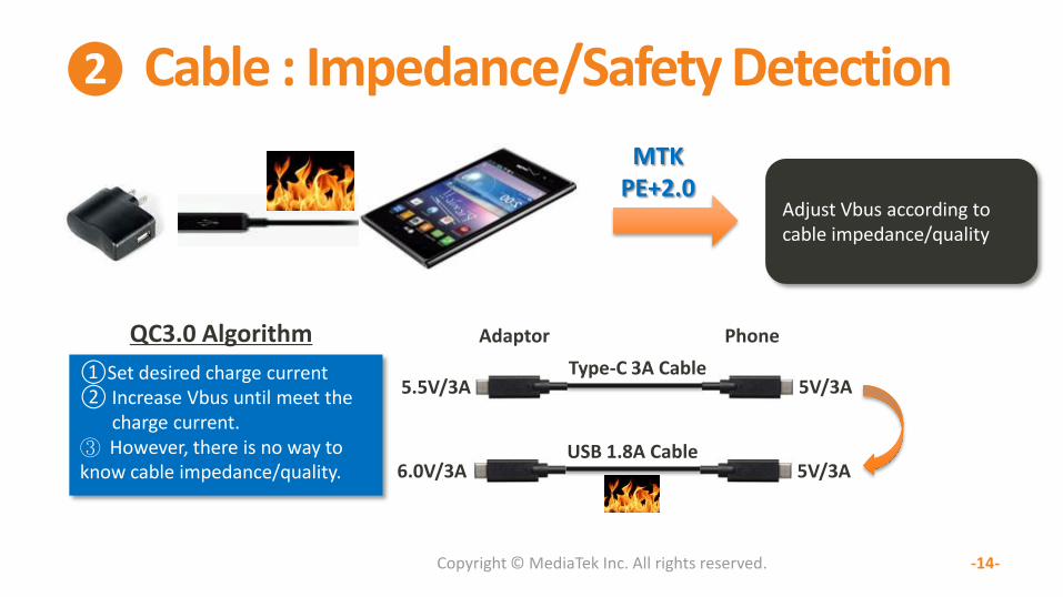
❷ Cable : Impedance/Safety Detection
Copyright © MediaTek Inc. All rights reserved. -14-
QC3.0 Algorithm
①Set desired charge current ② Increase Vbus until meet the charge current. ③ However, there is no way to know cable impedance/quality.
Adjust Vbus according to cable impedance/quality
MTK PE+2.0
Adaptor Phone
Type-C 3A Cable
USB 1.8A Cable
5.5V/3A 5V/3A
5V/3A 6.0V/3A

❷ Cable Impedance Measurement Cable R (Ω)
= (V_phone_a – V_phone_b) / 0.45A
[Cable Impedance Measurement]
(Assume TA compensation = 250mV@2A)
TA Cable Compensation Disabled
Cable R = 0.3Ω
TA Cable Compensation Enabled
Cable R = 0.175Ω
-15-
VBUS
IBUS Ib 900mA
Ia 450mA
V_phone_a
V_phone_b
V_adaptor_a V_adaptor_b

❸ Accurate Charge Path Impedance Compensation, extending CC period
Copyright © MediaTek Inc. All rights reserved. -16-
Accurate cell voltage can be measured inside the pack Over-estimated
cell voltage
4.35V
3.9V
CC Extension
MW3757 MW3793
MW3757: Protection + Monitor MW3793: Monitor (Exclusive for MediaTek)

PE+2.0 AC/DC & Charger IC Vendors iWatt (Dialog)
– iW1782 (primary side) + iW673 (synchronous rectifier, option for better efficiency)
On-bright (OB)
– OB2632+OB2607
– 奥海 (Aohai)/百俊达/科讯 (Kosun)
Fairchild – FAN602 (primary side) + FAN6290M (secondary side)
– Salcomp/辰陽 (Chenyang Electron)

Pump Express 3.0
18

PE 3.0 Advantage
Power Dissipation -60% The power dissipation can be reduced significantly by using
direct charge (without loss caused by switching charger)
Design for Safety Bi-directional communication between TA and phone Over 20 protection mechanisms
75% in 20 min. Utilize Step Charge and/or high-C-rate battery
5A+ Charging
Standardized Eco-system Type-C/PD cable, connector. Share the same eco-system
among PC/NB/monitor/phone

PE 3.0 System Concept
(36V)
USB PD VDM communication / Type-C 5A Cable
25W : 43mm x 43mm x 25mm (will be smaller for MP product)
AP battery
Switching Charger
VBAT VSYS
VBUS
D+/D-
CC1/CC2 Type-C/PD
I2C
Type
-C C
on
ne
ctor
Direct Charge Path
Conventional Charge Path

PE 3.0 Phone Impedance Control
R_CON1 R_CABLE R_CON2R_SW
R_C
From
VBUS
ICHG
ICHG
ICHG
ICHG
ICHG
ICHG
5.7mΩ 5.7mΩ
5mΩ
20mΩ
Totally
7 contacts
Totally
7 contacts
77.1mΩ
AWG22//
AWG28
100cm
1.For VBUS, (1 AWG22,52.9mΩ)//(3 AWG28,141.9mΩ).
2.For GND, (1 AWG22,52.9mΩ)//(3 AWG28,141.9mΩ).
16mΩ
RPCB
4mΩ
5mΩ
R_FG
R_Pcb_bat
5mΩ
R_p
Cell
Battery
Protector
30mΩ
R_b
5A
TA
Cable/Connector Phone
Battery
O Impedance (R) minimization is critical for power dissipation (Pd) reduction because Pd is in proportion to I2R. O A high-C-rate cell (usually ≥ 1.5C) with low DCR is a must. . However, you have to tradeoff C-rate and cell energy density.

Design for Safety
Subject TA Cable/
Connector Charger
Battery BIF with AP
Battery Protector
Identification
OVP
OCP
Thermal
Watchdog Timer
Impedance detect
PD adaptor
Battery AP
BIF Charger
Bi-direction
communication
Over 20 Protection Mechanisms

PE 3.0 AC/DC Vendor
Richtek – RT7786 (Primary) + RT7207 (Secondary)
Power Makers
23
TA Vendors Contact Person Phone Mobile Email
Salcomp 賽爾康 Lenny Lin 0920 363 552 [email protected]
Phihong Technology Co., Ltd. 飛宏 陳湘怡 Elaina Chen (886)-3-3277288 (TW) (886)972-637-968 (CN) (86)13910483959
SOLUM Co. Ltd. 搜路研電子 王秋東 Eric Wang (86) 10 8478 5696 (86) 152 0140 8181 [email protected]
FSP 全漢 賴怡秀 Stacy (886) 3-3759-888 # 1225
(TW) (886)960034264 [email protected]
Aohai 奧海
Huntkey 航嘉

Connector/Cable Vendor Info.
深圳捷訊光電科技 (Sunyking Technology Co. Ltd)
Cable: SK-USB31CC001
Connector: SK-CONNCF01
24
Connector/Cable Vendors Contact Person Phone Email
今浩
Ji-Haw Industrial Co., Ltd 賴建興 (Joe Lai)
Taiwan: +886_919_283_235 China: +86_186_824_270_15

PE 3.0 Target
Connector : Type-C@phone
Cable : A-2-C or C-2-C
Communication : USB PD (VDM)
Create a Low-voltage fast charge standard based on USB PD. Share same supply chain with PC/Monitor/NB/Tablet.
Copyright © MediaTek Inc. All rights reserved.
-25-

Q&A
26

PE3.0 FAQ (1/3)
Q: What is PE3.0? – A: It’s charge technology routing charge current directly from Adaptor to Battery.
Q: What is the advantage of PE3.0? – A: Much better charge efficiency (95%+), making high charge current possible.
(Traditional high-voltage fast charge technology ~ 90%)
Q: What is the required HW of PE3.0? – (1) 3-6V/5A+ Adaptor with USB PD VDM capability – (2) Smartphone with Type_C connector and USB PD VDM capability – (3) 5A cable – (4) A Battery with high Charge-Rate (C-rate).
• Example #1 : 5A charge current / 2500mAh battery = 2C (emerging) • Example #2 : 5A charge current / 3333mAh battery = 1.5C (commercial available)
– (5) Low-impedance design, including connector, cable, switch for charge, PCB, battery.
27

PE3.0 FAQ (2/3)
Q: How much does it cost? – (1) In the long run, type-C is the standard. So, assuming you already have type-C 3A cable, you
just need to upgrade to 5A cable. – (2) And, you must pay for adaptor with higher power (e.g. 15W 25W) & USB PD capability – (3) Phone: no cost up
Q: When is the mass production schedule of PE3.0? – A: Ready for mass production
Q: What is the target platform of PE3.0? – Mediatek X-series and P-series. For middle-end, it’s by request.
Q: Is PE3.0 safe? – Over 20 protection mechanisms are designed for ensuring safety of PE3.0.
28

PE3.0 FAQ (3/3)
Q: Can PE3.0 support communication via D+/D-?
– A: No, only USB PD
29


![[Enter Document title here] - MediaTek 2016 MediaTek Annual Report Table of Contents I. Letter to Shareholders II. Company Profile 1. MediaTek Company Profile 6 2. Milestones ...](https://static.fdocuments.in/doc/165x107/5aabf8fd7f8b9a59658c90f1/enter-document-title-here-mediatek-2016-mediatek-annual-report-table-of-contents.jpg)