Media Processing in Video Conferences for Cooperating Over the Top
127
Syed Safi Ali Shah Media Processing in Video Conferences for Cooperating Over the Top and Operator Based Networks School of Electrical Engineering Thesis submitted in partial fulfillment of the requirement for the degree of Master of Science in Technology Espoo 05.04.2012 Thesis supervisor: Professor Jörg Ott Thesis instructor: Kaisa Kettunen, M.Sc.
Transcript of Media Processing in Video Conferences for Cooperating Over the Top

Syed Safi Ali Shah
Media Processing in Video Conferences for Cooperating Over the Top and Operator Based Networks
School of Electrical Engineering
Thesis submitted in partial fulfillment of the requirement for the degree of
Master of Science in Technology
Espoo 05.04.2012
Thesis supervisor:
Professor Jörg Ott
Thesis instructor:
Kaisa Kettunen, M.Sc.
AALTO UNIVERSITY SCHOOL OF ELECTRICAL ENGINEERING
ABSTRACT OF THE MASTER’S THESIS
AUTHOR: Syed Safi Ali Shah
TITLE: Media Processing in Video Conferences for Cooperating Over the Top
and Operator Based Networks
DATE: April 05, 2012 LANGUAGE: English NUMBER OF PAGES: 104
FACULTY: Electronics, Communications and Automation
DEPARTMENT: Communications and Networking
PROFESSORSHIP: Networking Laboratory CODE: S-38
SUPERVISOR: Professor Jörg Ott
INSTRUCTOR: Kaisa Kettunen, M.Sc.
Telecom operators have dominated the communication industry for a long time
by providing services with guaranteed quality of service. Such services are
provided by the operator at the cost of maintaining a high grade network. With
the introduction of broadband and internet, many over the top (OTT) services
have emerged. These services use the underlying operator networks as a mere
bit pipe while all service intelligence resides in the application running on the
client device. Introduction of OTT services has seen a good response from
general users who are no longer bound to services provided by the network
operator. This in turn has caused operators and telecom companies to loose the
ownership of their customers.
This thesis takes media processing in video conferencing as a case study to
compare the two competing domains of operator networks and OTT networks.
Both domains offer video conferencing to end users, but they follow different
architectures. The study shows that OTT services can perform much better if
they utilize support of the underlying network. This will also bring the user base
back to the network operator. The proposal is to turn the competition into
cooperation between both parties.
Assessments are done from both technical as well as business perspectives to
assert that such cooperative agreements are possible and should be experimented
in real life.
KEYWORDS: Video Conference, Over The Top, Media Processing

ii
TABLE OF CONTENTS:
TABLE OF CONTENTS: ................................................................................... II
ACKNOWLEDGEMENTS ................................................................................. V
ABBREVIATIONS ............................................................................................ VI
LIST OF FIGURES ............................................................................................ IX
LIST OF TABLES .............................................................................................. XI
TERMINOLOGY ............................................................................................. XII
1 INTRODUCTION ........................................................................................ 1
1.1 PURPOSE OF THE THESIS ................................................................................................... 4
1.2 METHODOLOGY ................................................................................................................ 5
1.3 THESIS LAYOUT ................................................................................................................ 5
2 VIDEO CONFERENCING CONCEPTS .................................................... 6
2.1 SESSION ESTABLISHMENT/TEARDOWN.............................................................................. 7
2.2 CAPABILITY NEGOTIATION ............................................................................................... 9
2.3 MEDIA TRANSPORT ........................................................................................................ 10
2.4 INTER STREAM SYNCHRONIZATION ................................................................................ 10
2.5 CONFERENCING SUPPORT ............................................................................................... 11
2.6 CONFERENCE FLOOR CONTROL ...................................................................................... 12
2.7 MEDIA CODING .............................................................................................................. 13
2.7.1 H.264 Video Codec Overview .............................................................................. 14
2.8 SUMMARY: ..................................................................................................................... 18
3 MEDIA CONFERENCING ARCHITECTURES ...................................... 19
3.1 CENTRALIZED ................................................................................................................. 19
3.1.1 Central conference server .................................................................................... 20 3.1.2 End-system mixing ............................................................................................... 21
3.2 DECENTRALIZED ............................................................................................................ 23
3.2.1 Mesh Network (multi-unicast) .............................................................................. 23 3.2.2 Multicast .............................................................................................................. 24
3.3 HYBRID .......................................................................................................................... 25
3.4 COMPARISON OF CENTRALIZED AND DE-CENTRALIZED ARCHITECTURES........................ 26
iii
3.5 SUMMARY ...................................................................................................................... 29
4 MEDIA PROCESSING IN VIDEO CONFERENCES .............................. 30
4.1 MULTIPOINT CONTROL UNIT DESIGN AND ARCHITECTURE .............................................. 30
4.2 RESPONSIBILITIES OF AN MCU IN A CONFERENCE .......................................................... 31
4.2.1 MCU structural architecture ................................................................................ 32
4.3 MCU PROCESSOR AND BANDWIDTH REQUIREMENTS .................................................... 33
4.3.1 Processing Demands ............................................................................................ 33 4.3.2 Bandwidth Utilization .......................................................................................... 38
4.4 SUMMARY ...................................................................................................................... 42
5 MEDIA PROCESSING IN COMMERCIAL COMMUNICATION
NETWORKS ...................................................................................................... 44
5.1 MEDIA PROCESSING IN THE OPERATOR NETWORKS ......................................................... 44
5.1.1 Media Gateways ................................................................................................... 45 5.1.2 Session Border Controllers .................................................................................. 45 5.1.3 Application servers............................................................................................... 46
5.2 MEDIA PROCESSING IN OTT NETWORKS ......................................................................... 46
5.2.1 Mesh Network (Multi-Unicast)............................................................................. 48 5.2.2 Single peer............................................................................................................ 48 5.2.3 Multiple peers (cooperative mixing) .................................................................... 49 5.2.4 Conclusions on media processing in OTT networks ............................................ 56
5.3 SUMMARY ....................................................................................................................... 58
6 COOPERATION BETWEEN OTT AND OPERATOR NETWORKS .... 60
6.1 MOTIVATION FOR COOPERATION .................................................................................... 62
6.2 TECHNICAL REQUIREMENTS FOR INTERWORKING BETWEEN OTT AND OPERATOR
NETWORKS ............................................................................................................................... 63
6.2.1 Proxy Peers .......................................................................................................... 64 6.2.2 Service Discovery mechanisms ............................................................................ 68 6.2.3 Security policies in operator network .................................................................. 71 6.2.4 Signaling gateway ................................................................................................ 71
6.3 CALL CASES ................................................................................................................... 72
6.3.1 Establishing a conference .................................................................................... 72 6.3.2 Requesting a transcoder in a point to point call .................................................. 76 6.3.3 Requesting a transcoder in a media streaming session: ...................................... 78
6.4 CONTRACTUAL CHALLENGES IN CASE OF INTER OPERATION BETWEEN OTT AND
OPERATOR DOMAINS ................................................................................................................. 82
6.4.1 Authentication of users in operator networks ...................................................... 83 6.4.2 User authentication models in Over the top networks ......................................... 85

iv
6.4.3 Charging models for cooperating ott and operator networks .............................. 89
6.5 SUMMARY ....................................................................................................................... 92
7 SECURITY CONSIDERATIONS ............................................................. 94
7.1 TRUSTED NETWORK ....................................................................................................... 94
7.2 CONFIDENTIALITY .......................................................................................................... 95
7.2.1 Media processing by conference participants ...................................................... 96 7.2.2 Media processing by network hosted servers ....................................................... 97 7.2.3 Media processing by peers outside the conference .............................................. 97
7.3 USER PRIVACY ............................................................................................................... 98
8 CONCLUSIONS ...................................................................................... 100
8.1 FUTURE RESEARCH: ..................................................................................................... 102
REFERENCES ................................................................................................. 105
APPENDIX 1: SMART PHONES PROCESSING AND DISPLAY
CAPABILITIES ............................................................................................... 113
APPENDIX 2: DSL TYPES AND THEIR DATARATES ............................. 114

v
ACKNOWLEDGEMENTS
I would like to express my gratitude to Allah and then to all the people who
supported me during my thesis work: my wife, my parents, my friends at Aalto
University, and my colleagues at Ericsson.
A special thanks to Professor Jörg Ott for his useful insights and Kaisa Kettunen
for her constant guidance throughout my thesis work.
At last I would like to thank Kari Pekka Perttula, who pointed me in the right
direction and helped define the research topic.
Espoo, April 05, 2012.
Syed Safi Ali Shah
vi
ABBREVIATIONS
3G Third Generation
ADPCM Adaptive Differential Pulse Code Modulation
ADSL Asymmetric Digital Subscriber Line
API Application Programming Interface
AS Application Server
AVC Advanced Video Codec
B2BUA Back to Back User Agent
BFCP Binary Floor Control Protocol
CPU Central Processing Unit
CSCF Call Session Control Function
CSRC Contributing Source
DHT Distributed Hash Table
DNS Domain Name System
DSP Digital Signal Processing
DVD Digital Versatile Disk
FQDN Fully Qualified Domain Name
GSM Global System for Mobile Communication
HD High Definition
HLR Home Location Register
HSPA High Speed Packet Access
HSS Home Subscriber Server
HTTP Hypertext Transfer Protocol
IETF Internet Engineering Task Force
IMS IP Multimedia Subsystem
IP Internet Protocol

vii
ISDN Integrated Services Digital Network
ISP Internet Service Provider
ITU International Telecommunication Union
ITU-T International Telecommunication Union - Telecommunication
LAN Local Area Network
LTE Long Term Evolution
MC Multipoint Controller
MCU Multipoint Control Unit
MP Multipoint Processor
MPEG-2 Moving Pictures Experts Group - 2nd standard
MPEG-4 Moving Pictures Experts Group - 4th standard
MRFP Media Resource Function Processor
NAT Network Address Translator
NNI Network Network Interface
OTT Over The Top
P-CSCF Proxy Call Session Control Function
P2P Peer to Peer
P2PSIP Peer to Peer Session Initiation Protocol
PSNR Peak Signal to Noise Ratio
QoS Quality of Service
RTCP RTP Control Protocol
RTP Realtime Transport Protocol
RTT Round Trip Time
SAP Session Announcement Protocol
SBC Session Border Controller
SCCP Simple Conference Control Protocol
SD Standard Definition
viii
SDES Source Description
SDP Session Description Protocol
SIM Subscriber Identity Module
SIP Session Initiation Protocol
SOAP Simple Object Access Protocol
SRTP Secure Realtime Transport Protocol
Telco Telecommunications Company
TCS Terminal Capability Set
TLS Transport Layer Security
TV Television
UDP User Datagram Protocol
UMTS Universal Mobile Telecommunications System
UNI User Network Interface
URI Universal Resource Identifier
VBR Variable Bitrate
VOIP Voice over Internet Protocol
WLAN Wireless Local Area Network
WiFi Wireless Fidelity

ix
LIST OF FIGURES
Figure 2.1: Stages of a conference session .................................................................................... 6
Figure 2.2: Protocols used during conference sessions, categorized according to their
functionality ................................................................................................................................... 7
Figure 2.3: Session Initiation Protocol (SIP) call setup procedure .............................................. 8
Figure 2.4: H.225.0 call signaling protocol call setup procedure ................................................ 9
Figure 2.5: Audio and video are recorded and transmitted as separate streams ....................... 11
Figure 2.6: Comparison of bit rates between different video codecs .......................................... 16
Figure 2.7: CPU utilization during decoding process ................................................................ 17
Figure 3.1: Classification of media conference architectures ..................................................... 19
Figure 3.2: Central conference server based conference architecture ........................................ 20
Figure 3.3: End system mixing model for media conferences...................................................... 23
Figure 3.4: Mesh (multi-unicast) model of media conferences .................................................... 24
Figure 3.5: Multicast conference architecture ............................................................................ 25
Figure 3.6: Hybrid conference architecture. Signaling associations are centralized, media flow
is de-centralized. .......................................................................................................................... 26
Figure 4.1: Internal logical structure of an MCU ....................................................................... 32
Figure 4.2: Processor cycles requirements for SD video conferences......................................... 35
Figure 4.3: Processor cycles requirements for HD video conferences ........................................ 37
Figure 4.4: Bitrate variation in a high definition 720p video on YouTube ................................. 38
Figure 4.5: Required network bandwidth in video conferences ................................................... 40
Figure 4.6: Internet datarates available to average end user today . .......................................... 41
Figure 5.1: Cascaded MCUs ....................................................................................................... 50
Figure 5.2: MCUs arranged in a mesh ........................................................................................ 51
Figure 5.3: Possible scenarios in which MCUs can be arranged in a mesh ............................... 53
Figure 6.1: Example Skype network topology ............................................................................ 65
Figure 6.2: Proxy Peer example ................................................................................................. 67
Figure 6.3: Proxy peer receives external call and routes to internal peer .................................. 68
Figure 6.4: OTT domain user establishes a conference session using MCU in the operator
domain ......................................................................................................................................... 74
Figure 6.5: MCU in the operator network invites OTT users in a conference ............................ 75
Figure 6.6: Transcoder from an operator domain is used to resolve media incompatibilities in a
point to point call between two OTT users ................................................................................... 77

x
Figure 6.7: Example architecture for providing network hosted transcoding support in media
streaming sessions involving mobile clients ................................................................................ 80
Figure 6.7: IMS ISIM based authentication ................................................................................ 84
Figure 6.8: HTTP digest based authentication in SIP ................................................................ 85
Figure 6.10: Charging model for inter operation between conventional P2P networks and
operator networks ........................................................................................................................ 91
Figure 7.1: Establishing bi-directional trust ............................................................................... 95
xi
LIST OF TABLES
Table 2.1: Bit rates of video encoded with different codec (in Kbps) ......................................... 16
Table 2.2: CPU cycles (x106) per second per frame for decoding video streams ....................... 17
Table 3.1: Complexity analysis and comparison between different conference models .............. 27
Table 4.1: Required processor cycles for encoding and decoding H.264 S Video ...................... 34
Table 4.2: Required processor cycles for encoding and decoding H.264 HD Video ................... 36
Table 4.3: Average bit rates of video in media conference applications ..................................... 39
Table 4.4: Average video bit rates at an MCU in media conferences.......................................... 39
Table 4.5: Average bit rates for mobile users using different access technologies .................... 42

xii
TERMINOLOGY
MCU
Multipoint control unit. Although originally defined in the H.323 standard, this
document uses this term to generally refer to an element in a conference or
multi-party call, which is vested with the responsibility of maintaining signaling
dialogues with multiple participants in a conference. An MCU may also provide
support for media processing, such as mixing multiple streams into one stream
or transcoding streams by modifying their media attributes.
OTT
Over the top (OTT) services are services which use the underlying carrier
network as a bit pipe, while placing all the intelligence and decision logic on the
end client devices. This type of services are seen as a risk to the Internet Service
Providers (ISPs) and telecom operators since they use the network freely and
openly without much respect for the operator boundaries. Examples of such
OTT service providers are Skype [37], GoogleTalk [69] etc.
Operator Network
A network which is commissioned and administered by a well-established
telecom operator or an ISP. The services are hosted on servers residing inside
the network and are made available to the users registered in this network
against a certain charge. Operator networks are also often referred as “carrier-
networks” from the OTT service’s point of view.
Walled-garden
A network divided into separate and distinct operator domains through extensive
use of firewalls and Network Address Translators (NATs). The operator
determines which users get access to which of the services and applications.
This concept goes opposite to the open internet architecture.

1
1 INTRODUCTION
Communication networks have seen a very fast and large scale development in
the last decade. End users have upgraded their connections from a few kilobits
per second to many megabits per second of bandwidth. This increase in speed
and capacity has re-shaped the way people communicate over long distances.
We have seen a shift from simple text based communication to voice based
applications [1]. The latest addition to this ever expanding domain of
communication services is video based communication. Today people do not
just want to hear the person on the other side of the network, but they also want
to see who they are communicating with. This makes communications a much
richer interactive process. These evolving networks have enabled another
dimension of communication; video conferencing. The idea that many people
situated at geographically far off locations can simultaneously see and talk to
each other has now become a reality.
At the same time, organizations and individuals would like to have high
definition (HD) video support in video conferences, since the improved video
quality can add great value and much broader applicability to video
conferencing [2]. A few of the use cases where HD video conferencing is
expected to be helpful include medical procedures which could be carried out on
patients by different medical experts located at different geographic locations.
Also, employees of an organization no longer need to travel all the way to
different offices to meet and work with other people. Instead, they can simply
work together in teams over HD video conferences thus reducing the need for
physical travel. For collaborative research, participants can simply draw
something on a piece of paper and show it to the person on the other side. That
is to say, the experience becomes much more realistic and comfortable, and thus
it promises to save a lot of cost in terms of money and time that is otherwise
spent on traveling.
However just like voice, video communication has also seen the tussle between
the two main competing players in the industry [4]: Over the top (OTT) service

2
providers and the network operators. Both market players tend to offer similar
services to the end user, while the underlying technicalities of how these
services are delivered are very different. Network operators tend to host services
inside their networks and offer them as Value Added Services (VAS) to end
users. However OTT services are typically installed on the end users’ terminals
while they use the operator’s network as a bit pipe for transferring data. End
users simply want to be able to access their favorite service from any place and
any terminal they have, irrespective of the underlying technology or network
dynamics being used to deliver that service.
The competition between the OTT industry and network operators has continued
since the early days of Voice over Internet Protocol (VoIP) or IP telephony. This
competition with the OTT service providers lead to a general fear in the network
operator domain about prospects of a slowly decaying business. The rationale
behind the competition is straight forward. Operators tend to host the services
within their networks [5] and thus boast of the concept of an “intelligent
network”. The terminals in this case need to take minimum amount of load,
merely accessing the service from the network, while the network with its
reliable and powerful servers does everything for the end user. To make the
network “intelligent” and capable enough, operators invest heavily on their
infrastructure. This in turn means, that the end user is charged a considerable
amount of fee for the services he or she accesses. The OTT industry, on the
other hand simply uses the underlying network as a bit pipe to route data packets
through to end terminals, while all the logic is hosted on the end client devices.
The OTT services are in some cases unreliable but appear to be generally more
attractive to the consumer due to their minimal cost. The operators have for
many years now, blamed the OTT industry for using their networks without
compensating the operator for the services that are being offered through the use
of its network. Since the OTT applications only use the network to transmit bits
and bytes of information, the operator can only charge them for the use of
bandwidth and not on the basis of the provided service (data, voice, video etc).

3
Also, increasing competition from alternate access providers is forcing operators
to offer flat rate data subscription plans. Flat fee Internet access causes increase
in traffic volumes flowing through the network, a large part of which is P2P or
OTT traffic [6]. This increased demand and traffic on the network forces the
operator to invest in additional network capacity. This trend may lead to the
decoupling of traffic and revenue [7]. Therefore being a mere bit pipe is
generally not seen as a profitable business by operators as the revenue generated
may not be enough to cover the costs of carrying the OTT traffic [8]. Some
circles of telecom operators have gone the distance of trying to block or firewall
the OTT applications from accessing their network.
A network operator thus has to consider whether investing in expensive
hardware, software and maintaining a reliable service is a profitable business
scenario anymore. Or should the industry just accept that end devices today are
capable of handling their own loads and requirements, and thus network should
in fact be just a dumb bit pipe? This debate seems to put the OTT industry at an
advantage when considering IP telephony as the service of contention. With the
introduction of broadband and 3G networks, the end users got ample bandwidth
at their disposal to allow voice traffic to flow without major hiccups over the
best effort IP infrastructure, even in the absence of any particular QoS
guarantees in the network. Also as the client devices (including mobile handsets,
desktops and laptops) continuously evolved in terms of processing power and
memory, they could fulfill the needs of audio processing themselves. Thus the
OTT applications got more and more self reliant and required less or no support
from the network hosted intelligence.
However, video conferencing, which is going to be our focus in the rest of the
thesis, differs from VoIP scenario in two major ways. Firstly, it requires a
considerable amount of video processing which is more complex and
computationally intensive process as compared to audio processing. Secondly,
video packets are bulkier and need a fair amount of network bandwidth to make
sure they are delivered on time. It is primarily for these reasons that despite the

4
considerable amount of time since its introduction, video conferencing and
network collaborative environments still suffer from lack of quality [9]. This is
especially common in scenarios where conferencing applications run over third
party networks. The underlying network in such cases, does not provide much
assistance such as QoS (Quality of Service) guarantees to the conference
application. Participants on different sides of the video conference can see and
hear each other, but due to the lack of video quality the experience remains
unpleasant and the participants do not get the sense of really sitting in front of
each other in the same room. As we discuss further on in the thesis that the
network may be able to lend a helping hand in such scenarios by fulfilling the
requirements of the OTT applications.
Thus the question remains: is there still a way for the network operators and
OTT industry to cooperate with each other in order to bring better services to
end consumer and to turn this operator fear into profit?
1.1 PURPOSE OF THE THESIS
Specific to video conferencing, this thesis aims to evaluate the requirement of
high-end multipoint control units inside the network which are capable of
handling video mixing and video transcoding. The study aims to understand
whether the OTT services today have advanced to the point where they can
handle everything within the end systems without any support from the network.
If this is true then network operators can avoid heavy investments that go into
provisioning these services in their networks. On the other hand, if support for
media processing is still needed within the network, we investigate how the
OTT service providers can cooperate with the operator based networks to bring
better services to the end user. We also try to identify the benefits for the OTT
industry and network operators in case of cooperative agreements between both
of the market players.

5
1.2 METHODOLOGY
We start by reviewing the current literature available on the topic of video
conferencing. The literature review identifies some key research questions,
which we further investigate by taking measurements and well defined statistics.
These statistics clearly identify some room for improvement in the system. We
then highlight different possible solutions during brain storming sessions and
collaborative discussions. At the end, we formulate a concrete proposal. The
applicability of the proposal is evaluated in light of both technical and business
related demands. In the end, we identify some areas for future research.
1.3 THESIS STRUCTURE
The thesis is structured as follows. We begin in chapter 2 by introducing the
basic concepts of media conferencing. In chapter 3, we point out the various
topologies used in media conferencing architectures and present their mutual
comparisons. In chapter 4, we continue to study the current requirements posed
at the Multipoint Control Unit (MCU) for multiparty conference calls involving
video. Then we see how OTT services tend to accomplish multi-party control
tasks such as media mixing and transcoding. We then look into the dimension
of cooperation between operator networks and OTT service providers in chapter
5, and also discuss what benefits it holds for both parties. Chapter 6 then briefly
points out some security considerations in case of cooperative agreements
between OTT service providers and network operators. We then conclude in
chapter 7 by summing up the findings of the research and identifying some
future research areas.
6
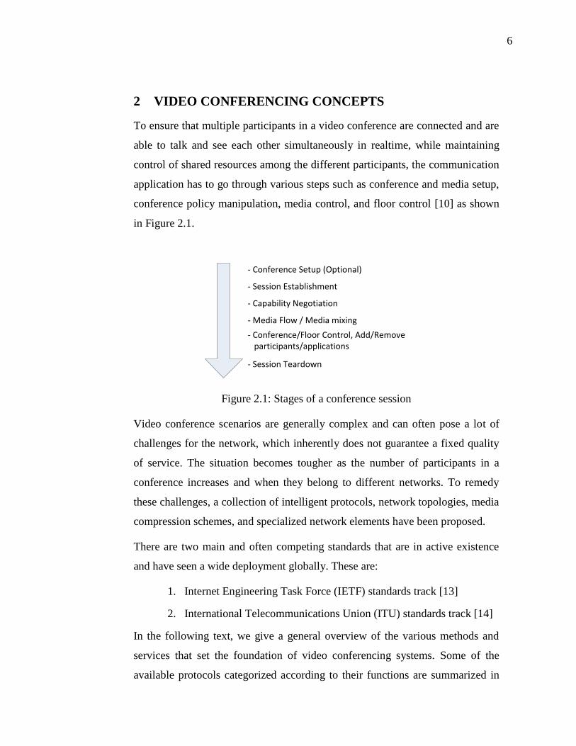
2 VIDEO CONFERENCING CONCEPTS
To ensure that multiple participants in a video conference are connected and are
able to talk and see each other simultaneously in realtime, while maintaining
control of shared resources among the different participants, the communication
application has to go through various steps such as conference and media setup,
conference policy manipulation, media control, and floor control [10] as shown
in Figure 2.1.
- Conference Setup (Optional)
- Session Establishment
- Capability Negotiation
- Media Flow / Media mixing
- Conference/Floor Control, Add/Remove participants/applications
- Session Teardown
Figure 2.1: Stages of a conference session
Video conference scenarios are generally complex and can often pose a lot of
challenges for the network, which inherently does not guarantee a fixed quality
of service. The situation becomes tougher as the number of participants in a
conference increases and when they belong to different networks. To remedy
these challenges, a collection of intelligent protocols, network topologies, media
compression schemes, and specialized network elements have been proposed.
There are two main and often competing standards that are in active existence
and have seen a wide deployment globally. These are:
1. Internet Engineering Task Force (IETF) standards track [13]
2. International Telecommunications Union (ITU) standards track [14]
In the following text, we give a general overview of the various methods and
services that set the foundation of video conferencing systems. Some of the
available protocols categorized according to their functions are summarized in

7
Figure 2.2. We will highlight both of the above mentioned standards wherever
applicable.
TCP/UDP TCP
H.2
25
.0 C
all Signalin
g
IP
UDP
SIP
SDP
HTTP
H.2
45
BFC
P
RTP
RTC
P
Encoded Media (G.729, H.264,
…)
Session Establish, Modify, Terminate
Capability Negotiation Floor Control Media Transport
ITU standard
IETF standard
ITU + IETF
Figure 2.2: Protocols used during conference sessions, categorized according to
their functionality
2.1 SESSION ESTABLISHMENT/TEARDOWN
Before any kind of media can start to flow between end parties in a conference,
connections must be established between them. In some conference topologies,
participants must connect to servers which provide functions such as media
conversion, mixing and other such applications. This phase, where the devices
are connected to each other, is referred to as session establishment. At the end of
the conversation, when participants wish to leave the conference, they must
close these connections. This is the session teardown phase.
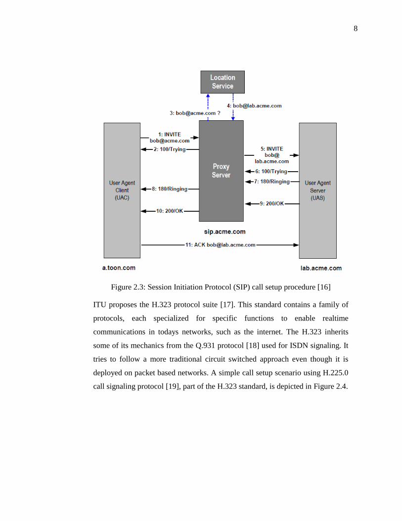
IETF proposes the use of Session Initiation Protocol (SIP) [75] for Session
Establishment, Modification and Teardown. SIP is a lightweight internet
friendly protocol. A basic session setup with SIP is depicted in Figure 2.3. After
this initial session establishment, media can start to flow between the end points.
8
Figure 2.3: Session Initiation Protocol (SIP) call setup procedure [16]
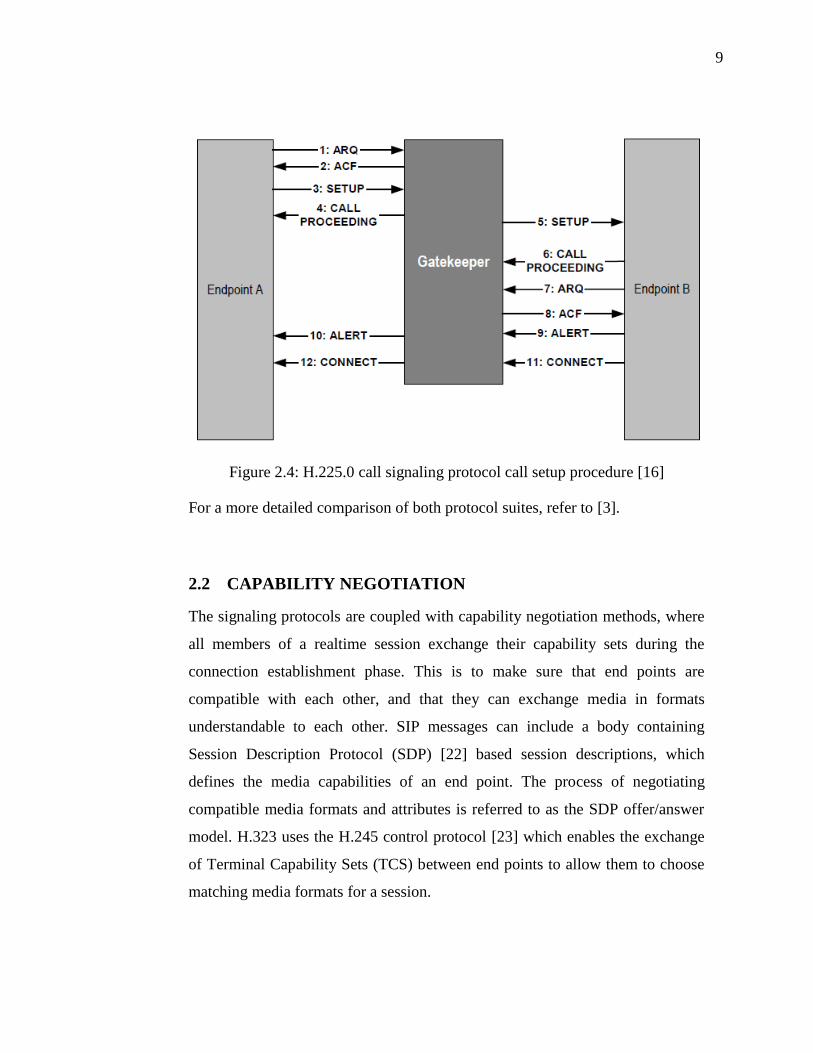
ITU proposes the H.323 protocol suite [17]. This standard contains a family of
protocols, each specialized for specific functions to enable realtime
communications in todays networks, such as the internet. The H.323 inherits
some of its mechanics from the Q.931 protocol [18] used for ISDN signaling. It
tries to follow a more traditional circuit switched approach even though it is
deployed on packet based networks. A simple call setup scenario using H.225.0
call signaling protocol [19], part of the H.323 standard, is depicted in Figure 2.4.
9
Figure 2.4: H.225.0 call signaling protocol call setup procedure [16]
For a more detailed comparison of both protocol suites, refer to [3].
2.2 CAPABILITY NEGOTIATION
The signaling protocols are coupled with capability negotiation methods, where
all members of a realtime session exchange their capability sets during the
connection establishment phase. This is to make sure that end points are
compatible with each other, and that they can exchange media in formats
understandable to each other. SIP messages can include a body containing
Session Description Protocol (SDP) [22] based session descriptions, which
defines the media capabilities of an end point. The process of negotiating
compatible media formats and attributes is referred to as the SDP offer/answer
model. H.323 uses the H.245 control protocol [23] which enables the exchange
of Terminal Capability Sets (TCS) between end points to allow them to choose
matching media formats for a session.

10
2.3 MEDIA TRANSPORT
Once the initial handshake is complete and matching media capability sets are
exchanged, media streams can start to flow between the end points. A
specialized application layer protocol named Realtime Transport Protocol (RTP)
[24] has been proposed by IETF and is by far the most widely deployed protocol
for transport of media streams in IP based networks. Both SIP architecture and
the H.323 protocol suite recommend the use of RTP for media exchange. RTP
by nature is independent of the underlying transport layer protocol, but it is
generally deployed over UDP in order to maintain steady throughput by
avoiding unnecessary re-transmissions of lost or delayed packets. Through the
use of sequence number and timestamps, RTP maintains orderly and
synchronized playback of realtime data. RTP is often (but not always)
accompanied by the RTP Control Protocol (RTCP) [24]. The purpose of this
control protocol is to exchange useful statistics about realtime packets between
the communicating parties, such as the number of packets lost, and thus to
estimate the condition of the link and the measures needed to improve the
quality of the realtime session.
2.4 INTER STREAM SYNCHRONIZATION
The use of RTP for media transport means that in case of video conferences,
audio and video packets are transmitted as separate media streams. The
motivation for de-coupling audio and video in RTP are given in [24]. These
media streams flow independent of each other through the entire network, as
shown in Figure 2.5, before reaching the end destination, where they are played
back to the end user. Because the streams flow independently in the network,
audio and video packets may arrive with differing delays at the receiver. In
addition to this, the video conferencing applications at the sender, receiver or an
intermediate server might have separate processing pipelines for audio and
video packets. Thus the audio and video streams need to be re-synchronized at
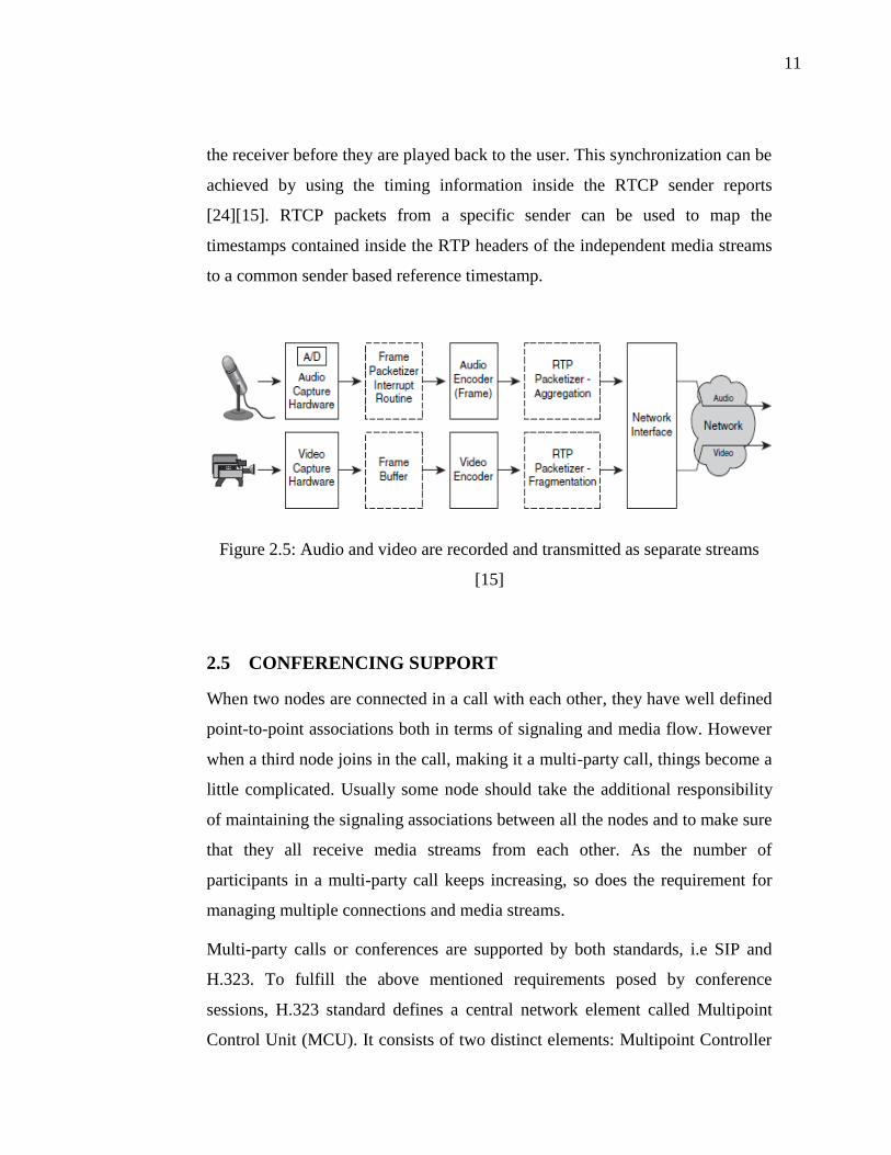
11
the receiver before they are played back to the user. This synchronization can be
achieved by using the timing information inside the RTCP sender reports
[24][15]. RTCP packets from a specific sender can be used to map the
timestamps contained inside the RTP headers of the independent media streams
to a common sender based reference timestamp.
Figure 2.5: Audio and video are recorded and transmitted as separate streams
[15]
2.5 CONFERENCING SUPPORT
When two nodes are connected in a call with each other, they have well defined
point-to-point associations both in terms of signaling and media flow. However
when a third node joins in the call, making it a multi-party call, things become a
little complicated. Usually some node should take the additional responsibility
of maintaining the signaling associations between all the nodes and to make sure
that they all receive media streams from each other. As the number of
participants in a multi-party call keeps increasing, so does the requirement for
managing multiple connections and media streams.
Multi-party calls or conferences are supported by both standards, i.e SIP and
H.323. To fulfill the above mentioned requirements posed by conference
sessions, H.323 standard defines a central network element called Multipoint
Control Unit (MCU). It consists of two distinct elements: Multipoint Controller
12
(MC) which is responsible for maintaining signaling associations among
different conference participants and optionally Multipoint Processors (MP)
which offers media processing support such as mixing and transcoding of the
media streams from different participants. Hence in a conference session,
usually all participants establish connections with the MCU which then makes
sure that all participants receive the mixed stream from each other on their
desired addresses.
SIP does not define a logically distinct element such as an MCU, and any user
agent can act as a focus for a multi-party session [40]. The focus acts as the
center of the conference and its responsibility is to maintain signaling
relationships with all conference participants while maintaining full control over
the conference. In general, the focus can be any user agent with B2BUA (Back
to Back User Agent) functionality. The media processing requirements in SIP
conferences are handled by mixers, which are logically disjoint elements and
can be controlled by the focus using third party protocols. Physically, a mixer
may or may not be a part of the focus. The focus uses third party call control
mechanisms to instruct all conference members to direct their media streams to
the mixer.
Both standards can support different architectures and topologies in which the
conferencing nodes are connected with each other and how the responsibilities
are shared among them. Details on conference architectures are discussed in
Section 3.
2.6 CONFERENCE FLOOR CONTROL
Another aspect particular to multi-party calls is that of floor control. Floor
control basically implies controlling access to shared resources in a conference.
For example the mixer can be instructed to choose only part of the incoming
streams to be mixed together and sent to all participants. In other words, a floor
control protocol can be used to administer a conference and to allow only

13
certain members of the conference to actively speak and be heard by all
members, while the passive members only watch/listen to the active members.
Methods which allow members of a conference to request floor and then allow a
controlling user/server to grant the floor to a member based on certain policy
need to be in place. Such conference control and conference management is
defined as part of the H.245 protocol within the H.323 protocol suite. SIP,
however, does not provide a standardized method of implementing such
functionality, but instead leaves room for various protocols to be plugged into
serve this purpose. Many protocols have been proposed, such as the Simple
conference control protocol (SCCP) [20] which mainly deals with tightly
coupled conferences and assumes a reliable transport infrastructure or using
Simple Object Access Protocol (SOAP) [12] for implementing floor control.
The Binary Floor Control Protocol (BFCP) [11] can also be used for this
purpose in a conference session.
2.7 MEDIA CODING
In the telecommunication world, extra bandwidth means extra cost. It is
infeasible to transport uncompressed audio/video streams over networks which
are already low on bandwidth and are being shared by many users
simultaneously. For this reason media streaming applications generally deploy
intelligent and effective audio and video coding algorithms, which give
maximum quality to the end user at minimal bit rates.
There are many audio and video compression standards, referred to as “codecs”.
One can choose which codec to use depending upon the application, such as
digital TV broadcast, DVD movies, media streaming over the internet etc. Most
of these codecs employ lossy coding schemes. This means that during
compression, some information from the audio or video packets has to be
dropped out thus causing a degradation of user perceived quality at the receiving
end.

14
In video conference systems, multiple audio and video streams have to be sent
and received in realtime among many participants. The available bandwidth on
the network links thus becomes a severe bottleneck. An intelligent choice of a
media codec can greatly help tackle the problem of scarce bandwidth by
compressing media into smaller size while maintaining good quality.
ITU has specified a number of audio and video coding standards that can be
used in video conference applications. These include:
Video
H.261, originally specified in 1988 for video transmission over ISDN
lines.
H.263, specified in 1995, as a replacement of H.261 for low bitrate
applications
H.264, specified in 2003. Has a lot of improvement in compression ratio
over its predecessor standard.
Audio
G.711, 64 Kbps, Comes in two flavors: A-law and mu-law
G.722, 48/56/64 Kbps ADPCM 7Khz audio bandwidth
G.728, 16 Kbps
G.723.1, 5.3/6.3 Kbps, 30ms frame size
G.729, 8 Kbps, 10ms frame size
2.7.1 H.264 VIDEO CODEC OVERVIEW
The ITU-T specified H.264 is today’s video codec of choice for nearly all
applications. It is also referred to as the Advanced Video Coding (AVC) or the
MPEG-4 part 10. The main motivation behind developing this coding standard
was better coding efficiency as compared to its predecessor codecs. Better and

15
more complex compression algorithms are employed which guarantee smaller
bitrates without the compromise on video quality. This makes H.264 one of the
forerunners in network friendly codecs, using minimal bandwidth for better
quality videos which are used for both conversational (video telephony, video
conferencing) as well as non-conversational (Video on demand, TV broadcasts,
media streaming) applications. However, this efficiency in terms of bitrate
comes at a tradeoff for processing demands. The H.264 encoding and decoding
algorithms require fairly complex prediction and transforms thus making the
process computationally much more intense than previous coding standards.
To understand the bandwidth and computational characteristics of H.264 video
codec, studies have been conducted with different encoders and decoders.
Alvarez et al. [27] have performed detailed tests of different sample video
sequences using both MPEG-2 video codec (also known as the H.262), and the
H-264 encoding. The results are quite elaborate but we summarize them in the
tables below. The referred decoder are the following:
H.264 = FFMPEG highly optimized decoder
MPEG4 = XviD MPEG-4 decoder
MPEG2 = libmpeg2 MPEG-2 decoder
A. Network Bandwidth consumption
H.264 is designed to be a bandwidth conserving codec. It aims at providing the
same visual experience to the audience that its predecessor codecs would deliver
at much higher bitrates. In general, the H.264 is said to provide as much as 50%
of bitrate saving in video streaming applications [30]. To reduce the bandwidth
demands, it uses a VBR (Variable bit rate) profile, which allows less bits per
frame to be used when there is less motion in the video.
The bandwidth depends on a lot of other parameters apart from the resolution of
the video. The below mentioned bitrates are for the same sample videos encoded
with different codecs to give almost same PSNR in the encoded video stream.

16
That is to say that the bitrates differ depending on the codec used, when the
encoded videos have similar visual quality.
Video
Resolution
H.264
(kbps)
MPEG4
(kbps)
MPEG2
(kbps)
729x576 2033 2236 6318
1280x720 3471 4050 10010
1920x1088 6724 8064 17723
Table 2.1: Bit rates of video encoded with different codec (in Kbps) [27]
Bandwidth comparison between video
codecs
0
5000
10000
15000
20000
729x576 1280x720 1920x1088
Video resolution
Bit
rate
(kb
ps)
H.264
MPEG4
MPEG2
Figure 2.6: Comparison of bit rates between different video codecs [27]
B. CPU cycles utilization
Similar to the case above, the CPU utilization is plotted for decoding
videos with different codecs having similar PSNR i.e. visual quality. The data
presented in Table 2.2 serves as a good illustration of the fact that H.264 is
much more processor intensive as compared to its predecessor codecs. It is

17
worth while to note that decoding isn’t the only task requiring considerable
amount of CPU cycles, but as we will see later in Section 4.3.1, encoding is
generally tougher than decoding in terms of CPU requirements. Thus encoding
must also be considered when dimensioning systems.
Resolution H.264 MPEG4 MPEG2
729x576 48 34 7,3
1280x720 99 73 14
1920x1088 213 165 31,8
Table 2.2: CPU cycles (x106) per second per frame for decoding video streams
[27]
CPU requirement comaprison between video
codecs
0
50
100
150
200
250
729x576 1280x720 1920x1088
Frame resolution
CP
U c
ycle
s (
x10^
6)
per
seco
nd
per
fram
e
H.264
MPEG4
MPEG2
Figure 2.7: CPU utilization during decoding process [27]
C. Conclusions
An analysis of the results shows that H.264 on average offers 64% bandwidth
saving as compared to the MPEG-2 codec. This high compression is, however,
achieved at the cost of complex algorithms, which take more CPU cycles and

18
instructions to evaluate. On average, the H.264 codec takes about 7 times more
CPU cycles per frame as compared to MPEG-2 for the same video sequence.
There are two vital resources at hand which we try to conserve in internet based
streaming or conferencing; bandwidth and the computational power. Trying to
compress the video stream to make it more bandwidth friendly will require the
use of more complex algorithms, which in turn means more processing cycles.
On the other hand, saving on the processor power thus evading complex
compression algorithms will adversely affect the bandwidth utilization.
2.8 SUMMARY:
To summarize, we see that video conferences involve elaborate procedures and
must follow certain protocols in order to make sure that all participants can see
and hear each other. Generally a conference proceeds through a series of stages
such as the conference setup (optional), session establishment, capability
negotiation, media transfer, floor control (optional) and finally session
teardown. There are two prominent standardization bodies namely ITU and
IETF who have been actively involved in proposing protocols and standards
governing the realtime communications over packet switched networks. These
standards are also applicable to multi party calls or conference sessions.
Another aspect that plays an important role in video conferences is the choice of
video codecs. We highlight some of the key properties of the currently well
known and widely used video codec H.264 and compare it to its predecessor
codecs. The findings suggest that H.264 gives much better bandwidth efficiency
compared to its predecessor codec but at the cost of increased processing power
for decoding and encoding.
Having covered these key concepts that are fundamental to all conferences over
packet switched networks, we will delve deeper into the various conference
architectures and topologies in the next chapter.

19
3 MEDIA CONFERENCING ARCHITECTURES
Media conferencing by nature is an elaborate and complex communication
scenario. As the number of participant nodes in a session increases, there are
more ways in which they can be arranged in the network [41]. These different
possibilities are summarized in the chart below.
Media Conference Architectures
Decentralized
Hybrid
Centralied
Conference Server Based
End System Mixing
Dial-In
Dial-Out
Multi Unicast
Multicast
Figure 3.1: Classification of media conference architectures
In this chapter we will take a closer look at each one of these conference
architectures. Although the following architectures can be implemented using
any signaling protocol of choice, we will primarily discuss examples from SIP
wherever applicable [41]. Similar examples for other signaling protocols, such
as H.323, can be found in literature.
3.1 CENTRALIZED
In the centralized model, the conference participants are tied together through a
central node. There are two variants of this as described below.
20
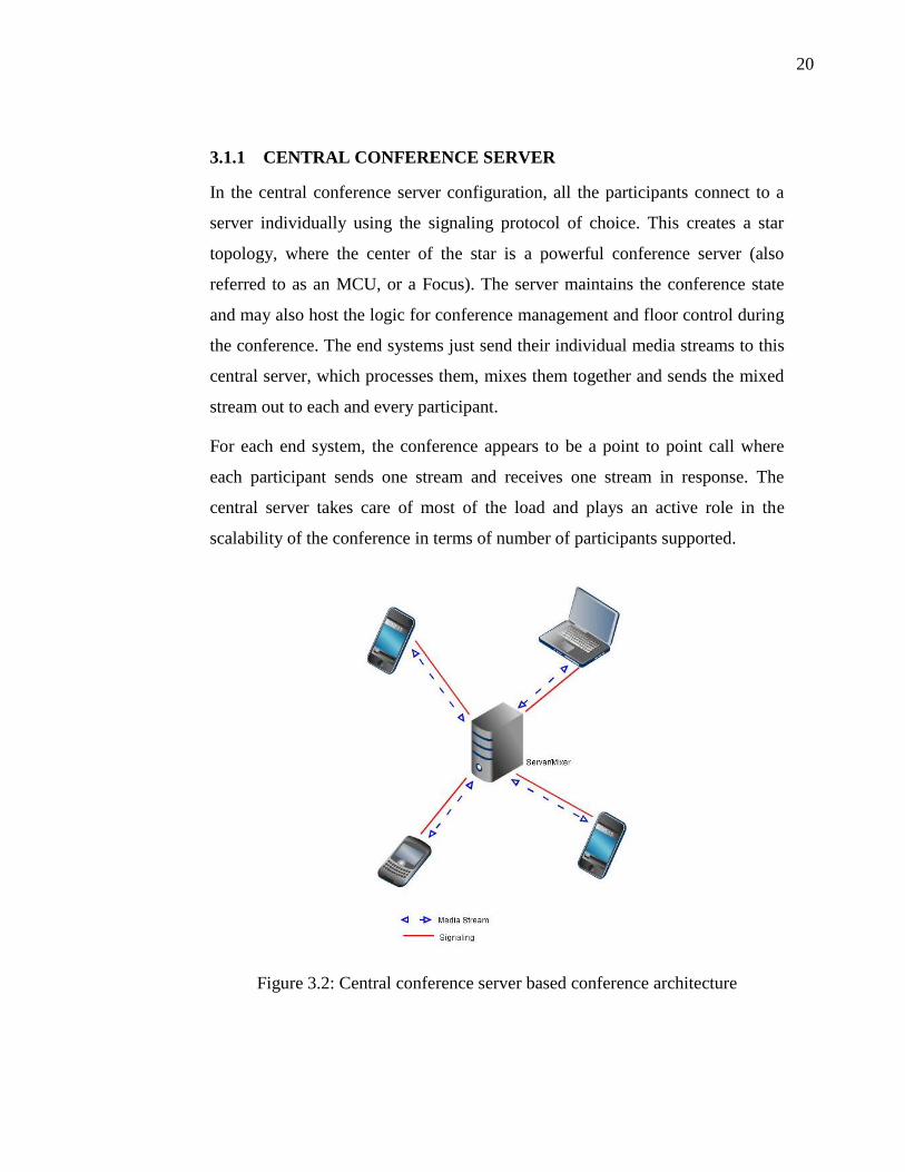
3.1.1 CENTRAL CONFERENCE SERVER
In the central conference server configuration, all the participants connect to a
server individually using the signaling protocol of choice. This creates a star
topology, where the center of the star is a powerful conference server (also
referred to as an MCU, or a Focus). The server maintains the conference state
and may also host the logic for conference management and floor control during
the conference. The end systems just send their individual media streams to this
central server, which processes them, mixes them together and sends the mixed
stream out to each and every participant.
For each end system, the conference appears to be a point to point call where
each participant sends one stream and receives one stream in response. The
central server takes care of most of the load and plays an active role in the
scalability of the conference in terms of number of participants supported.
Figure 3.2: Central conference server based conference architecture

21
The central conference server architecture can still be implemented in two
different ways depending on how the conference is set-up and how participants
are added to it.
A) Dial-in Conferences
In the Dial-In type, the URI or address of the conference is published, and all
users can establish a connection to the server individually. Since there can be
simultaneously any number of conferences hosted by the conference server, it is
important for the central server to know which users belong to which
conference. This can be done for example by keeping the address specific to
each conference. A conference can have an ID number and that can be reflected
in the URI (for example [email protected]). More users can be
added to the conference later by providing them the address of the conference
server. This can be achieved for example by sending a SIP REFER message
containing the URI of the conference to the user.
B) Dial-out Conferences
In Dial-out type of conference, the central server or the focus of the conference
initiates connections to each participant asking them to join the conference. In a
practical scenario, one user would first establish a connection with the server
and then provide it a list of rest of the participants which should be invited to the
conference. In SIP, this can be achieved by including the recipient-list [35] in
the body of the first INVITE message sent to the server. The server on receipt of
the INVITE can then process the recipient-list and in turn send INVITE
messages to all of the URIs listed in the recipient list. More users can be added
later on by sending a REFER message to the central server, which in turn can
send INVITE to the requested user.
3.1.2 END-SYSTEM MIXING
End system mixing is another type of centralized conference architecture, even
though it does not involve any specialized central server to manage the
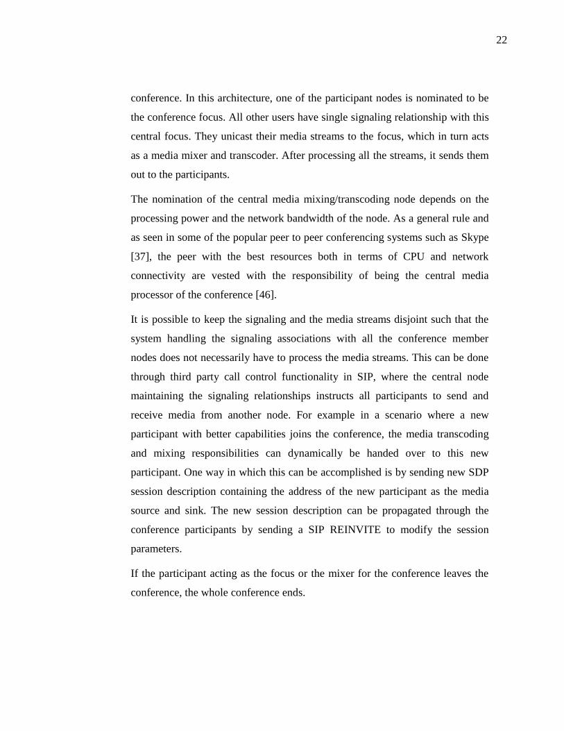
22
conference. In this architecture, one of the participant nodes is nominated to be
the conference focus. All other users have single signaling relationship with this
central focus. They unicast their media streams to the focus, which in turn acts
as a media mixer and transcoder. After processing all the streams, it sends them
out to the participants.
The nomination of the central media mixing/transcoding node depends on the
processing power and the network bandwidth of the node. As a general rule and
as seen in some of the popular peer to peer conferencing systems such as Skype
[37], the peer with the best resources both in terms of CPU and network
connectivity are vested with the responsibility of being the central media
processor of the conference [46].
It is possible to keep the signaling and the media streams disjoint such that the
system handling the signaling associations with all the conference member
nodes does not necessarily have to process the media streams. This can be done
through third party call control functionality in SIP, where the central node
maintaining the signaling relationships instructs all participants to send and
receive media from another node. For example in a scenario where a new
participant with better capabilities joins the conference, the media transcoding
and mixing responsibilities can dynamically be handed over to this new
participant. One way in which this can be accomplished is by sending new SDP
session description containing the address of the new participant as the media
source and sink. The new session description can be propagated through the
conference participants by sending a SIP REINVITE to modify the session
parameters.
If the participant acting as the focus or the mixer for the conference leaves the
conference, the whole conference ends.

23
Figure 3.3: End system mixing model for media conferences
3.2 DECENTRALIZED
In decentralized architecture of media conferences, there is no central authority
vested with the responsibility of keeping the participants tied together. All
participants are considered equal and the conferencing tasks, such as signaling,
media mixing etc are shared amongst them.
3.2.1 MESH NETWORK (MULTI-UNICAST)
In a mesh network, each and every participant maintains a connection with
every other member. Every user unicasts his stream to all other members in the
conference and receives the streams from all other active members. This is the
reason why this scheme is also referred to as multi-unicasting. Every participant
performs the media stream mixing individually for itself and it does not forward
the mixed stream to anyone. Compared to the end system mixing model, this
reduces the processing load (of encoding mixed media stream) on the end
systems, but the bandwidth demands remain still quite high [36]. For N
participant conference, where all users are actively sending media, an end point
will need to send N-1 streams and receive the equal amount as well.

24
Figure 3.4: Mesh (multi-unicast) model of media conferences
3.2.2 MULTICAST
In the multicast model of conference, the initial signaling procedure is
responsible for announcing the multicast address and the ports which will be
used to send and receive media streams. This can be done for example through
SIP INVITE messages or through SAP (Session Announcement Protocol) [38].
Once all the participants know about the multicast group address where the
conference is taking place, they can open their ports and simply start
sending/receiving on the multicast address to participate in the conference. It
should be noted that signaling is still point to point. It is only the media streams
that are multicasted. The model relies on the deployment of multicast on the
lower layers such as the IP layer.
It has been seen that multicast deployment remains limited to local area
networks, and the internet still does not allow large scale multicasting. Thus the
applicability of this model is limited to local networks only.

25
Once again, the mixing process is a responsibility of the end systems, since no
central mixer is present. However, there is a saving in upstream bandwidth as
compared to the multi-unicast architecture. Each participant only has to send out
his media stream once to the multicast group (as opposed to unicasting multiple
copies of the same media stream for each participant), after which it becomes
the responsibility of the multicast network to deliver it to all nodes part of that
group.
Figure 3.5: Multicast conference architecture
3.3 HYBRID
The hybrid model is a combination of the centralized and distributed models.
The central conference server only handles the signaling and thus maintains
control over the conference state. The media streams flow directly between the
conference members either through multiple unicast streams or through
multicast. The central server can use third party call control mechanisms [39] to
allow new participants to send/receive media to all other participants of the
conference. “As a result, if there are N participants in the conference, there will
be a single dialog between each participant and the focus, but the session
description associated with that dialog will be constructed to allow media to be

26
distributed amongst the participants” [40]. The motivation of using such a
model for conference can be that the central conference server does not have
enough resources to handle the media manipulation/mixing processes, so it
prefers the end systems to handle the media without involving the central server
in it. At the same time, conference control is maintained by staying inside the
signaling path. The central server can always remove any participant from the
conference, add a new one and maintain useful statistics about the conference.
Figure 3.6: Hybrid conference architecture. Signaling associations are
centralized, media flow is de-centralized.
3.4 COMPARISON OF CENTRALIZED AND DE-
CENTRALIZED ARCHITECTURES
All of the architectures discussed above have their pros and cons, yet they
remain in active use. We will now summarize the key differences in the above
mentioned conference architectures.
Load Distribution: In the centralized architecture, the load is
concentrated on one central entity which is responsible for the

27
transcoding and mixing of all media streams. This takes the load away
from all end systems and thus makes it possible for lower end devices,
having less computational or bandwidth capacity, to participate in the
conference. In the de-centralized architecture, the load is distributed to
end systems. While this removes the requirement of one powerful central
system, but it does pose a certain minimum amount of requirements on
end devices to join the conference. As the size of the conference
increases, end nodes might need to handle (receive, decode, encode and
send) more media streams. This can result in some nodes exceeding their
available resources, either in terms of computational power or network
bandwidth and thus will not be able to participate fully in the conference.
In table 3.1, we make a more formal comparison of different
architectures and their complexity in terms of bandwidth as well as
processor demands.
Topology Centralized Mesh Multicast
Server/mixing-endsystem CPU O(N) N/A N/A
Server/mixing-endsystem BW downstream O(N) N/A N/A
Server/mixing-endsystem BW upstream O(N) N/A N/A
Endsystem CPU O(1) O(N) O(N)
Endsystem BW downstream O(1) O(N) O(N)
Endsystem BW upstream O(1) O(N) O(1)
Table 3.1: Complexity analysis and comparison between different conference
models
Conference control and administration: The centralized architecture is
better suited for conference control than the de-centralized architecture.
In de-centralized topology, all conference participants establish
individual connections with each other. Consequently, it becomes
difficult to manage the conference (for example accepting and removing
participants) and maintain realtime conference state. This includes
participants’ presence information, conference floor control state and
other useful statistics concerning the conference. In contrast, in
28
centralized conferences the central server/node is always inside the
signaling/media path connecting different participants and thus it
governs the state of the conference at any time. Thus, it is easy for an
administrator to enforce conference policy.
Identification of conference participants: De-centralized conferences
have an edge over their centralized counterparts in terms of identifying
conference participants. In centralized architectures, all end nodes have
only one signaling association with the central server/node which sends
them the mixed media stream. In such cases, the identities of all the
participants must be explicitly mentioned in the media stream or through
some other conference control protocol. For example, RTP headers can
contain the identities of all the nodes contributing to the mixed media
stream, inside the contributing source (CSRC) header field which when
used with RTCP Source Description (SDES) reports can announce a list
of conference participants. But it is solely the responsibility of the
central server/node to add this information to the RTP headers or RTCP
reports while it is mixing various media streams. In contrast, in de-
centralized architectures all the participants are receiving individual
media streams from all other members of the conference and thus
identifying the conference participants at any time is not an issue. No
separate means need to be put into place to announce the identities of the
conference participants.
Robustness: The centralized architecture, due to its central processing is
more susceptible to threats pertaining to a single point of failure. If the
central node handling all signaling and media streams is attacked or dis-
connected from the network, the whole conference simply terminates.
De-centralized architectures are more resilient to infrequent node
disconnections.

29
3.5 SUMMARY
There are different architectures in which conferences can be setup. Mainly
these can be organized in two broad categories namely centralized and de-
centralized. Choosing a specific architecture generally means deciding how
responsibilities will be shared among different nodes in a conference.
Availability of resources at participant nodes or in the network also dictates
which architecture will be suitable for a certain conference session.
In general it is seen that centralized architectures give better control over the
conference, and concentrate the load (both in terms of CPU and network
bandwidth) on one central node whether that is a conference server or a
resourceful end system. While their de-centralized counterparts distribute the
load on participant nodes thus reducing the need for one powerful node but
consequently end nodes have to deal with their share of the load. At the same
time we can argue that this makes the system more robust by eliminating a
single point of failure.
Hence, we observe that both architectures have their advantages and
disadvantages. In following sections we will see how and under what
circumstances these both architectures are taken into use in today's networks.

30
4 MEDIA PROCESSING IN VIDEO CONFERENCES
A vital segment of the whole conferencing architecture is media processing.
Once the signaling has established required connections and all the conference
members have joined the conference in the required topology, it is time to
distribute the media streams in a manner that everyone can listen/see the desired
participants simultaneously. This means that the individual media streams
originating at each conference participant need to be mixed or (if needed)
transformed in some way with other media streams. As discussed in chapter 3.1,
this task is handled by an MCU in centralized conferences and is pushed to end
systems in de-centralized architectures. In the following sections, we will
primarily be focusing on centralized architecture as it remains to be more
popular with large scale conferences.
4.1 MULTIPOINT CONTROL UNIT DESIGN AND
ARCHITECTURE
An MCU acts as the central node both in signaling and media planes in the
centralized conference architecture. All participants of the conference are tightly
connected with the MCU. That is, each participant establishes a point to point
association with the MCU and all media traffic for all participants flows through
it. Due to the huge media processing demands on the MCU, it is generally built
on high performance media processing DSP chips with realtime media handling
capabilities. The hardware and software capabilities of an MCU, although
necessary for multiparty conference calls, can also be used in point to point calls
where both end systems of the call do not have compatible media capabilities.
Such cases are generally resolved within the capability negotiation procedures
that take place during the session establishment time. However, in some cases,
due to the acute difference in the devices, even the initial capability negotiation
phase might not resolve into successful matching media attributes. In such a

31
scenario there is a need for a media transcoder which can convert the media into
compatible formats for both end points and make the communication possible.
4.2 RESPONSIBILITIES OF AN MCU IN A CONFERENCE
In the signaling plane, MCU is assigned the responsibility of managing multiple
dialogues, one for each conference participant. In the control plane, the MCU
can be used in conjunction with floor control protocols, where different
participants can dictate their right to speak or use other resources in the
conference. As one MCU generally hosts multiple conferences simultaneously,
mechanisms to maintain and to control different simultaneous and disjoint
conferences must be implemented.
In the media plane, which will be the focus of the rest of the chapter, the MCU
has the following main responsibilities:
Receive media streams from all active participants of the conference.
Active participants are defined as those, which are generating media
streams in realtime. Such participants can be distinguished from the
passive participants which are in a listen-only state, i.e. receive media
streams from the active participants but do not generate any media
streams of their own. For example, in a class room conference between
the students and the teacher, the teacher is the active participant for most
of the time while the students are the passive participants.
Decode the media streams received from active participants.
Apply transformations as necessary to the decoded media streams (such
as re-size, change color depth, add a textual layer over video, or re-shape
video)
Mix together the media streams in realtime to generate a composite
mixed stream. This in turn might require the MCU to generate one
separate mixed stream destined for each participant. For example in
32
Figure 4.1, node A receives a mixture of all streams except the one
originating from A itself.
Encode the mixed media stream for delivery to all participants of the
conference. This step can vary depending upon the capabilities of the
end client devices and their access network characteristics. If all devices
have (almost) similar capabilities (such a screen size, video resolution
display, video/audio codec support, network bandwidth or capacity), the
same encoding can be applied for all participants. However, in case of
differences between the end devices, a separate media stream with
varying frame rate or bit rate values will be encoded depending upon the
requirements of each client and then sent out to each participant.
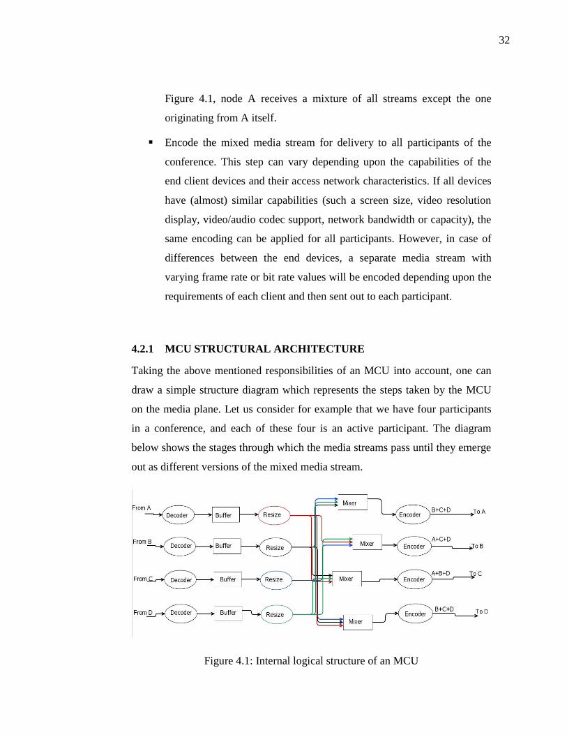
4.2.1 MCU STRUCTURAL ARCHITECTURE
Taking the above mentioned responsibilities of an MCU into account, one can
draw a simple structure diagram which represents the steps taken by the MCU
on the media plane. Let us consider for example that we have four participants
in a conference, and each of these four is an active participant. The diagram
below shows the stages through which the media streams pass until they emerge
out as different versions of the mixed media stream.
Figure 4.1: Internal logical structure of an MCU

33
Looking at this diagram, we can easily see that it consists of a number of steps,
many of which require active processing from the CPU and pose huge demands
on the bandwidth.
4.3 MCU PROCESSOR AND BANDWIDTH REQUIREMENTS
Fulfilling these responsibilities discussed in previous section adds processor and
bandwidth load on the MCU. Additionally there are a few factors which play an
important role in defining how much CPU and bandwidth is required for media
transcoding/mixing. These are:
Video resolution: number of pixels in one video frame
Video Frame Rate: number of frames per second that are throttled
through to and from the MCU
Video Codec: defines the compression and other algorithms that can
affect the bit rate of the video stream and also the computational
complexity involved in the encoding and decoding processes
Audio codec and bit rate accompanying the video: audio and video go as
separate streams over the IP network, and thus will need to be mixed
separately by the MCU.
4.3.1 PROCESSING DEMANDS
We will now look at the requirements posed on the processor by the
transcoding/mixing tasks that an MCU must perform in realtime.
A. Standard Definition Video
First we take the case of standard definition video with a resolution of 640 × 360
pixels. It is also known as nHD resolution. There are other commonly used
resolutions for video conferencing such as CIF (352 × 288) and 4CIF (704 ×
576), but nHD (640 × 360) was chosen for the ease of comparison with HD
(1280 × 720) since in terms of pixels its frame is exactly one fourth the size of a
34
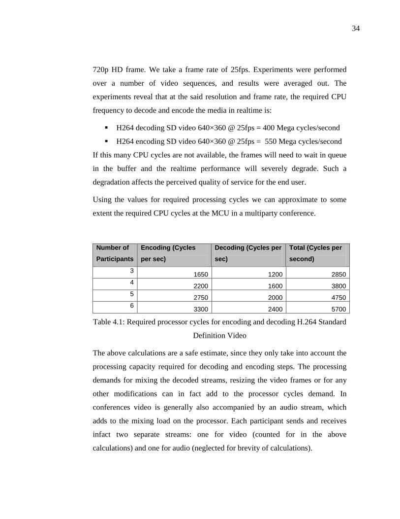
720p HD frame. We take a frame rate of 25fps. Experiments were performed
over a number of video sequences, and results were averaged out. The
experiments reveal that at the said resolution and frame rate, the required CPU
frequency to decode and encode the media in realtime is:
H264 decoding SD video 640×360 @ 25fps = 400 Mega cycles/second
H264 encoding SD video 640×360 @ 25fps = 550 Mega cycles/second
If this many CPU cycles are not available, the frames will need to wait in queue
in the buffer and the realtime performance will severely degrade. Such a
degradation affects the perceived quality of service for the end user.
Using the values for required processing cycles we can approximate to some
extent the required CPU cycles at the MCU in a multiparty conference.
Number of
Participants
Encoding (Cycles
per sec)
Decoding (Cycles per
sec)
Total (Cycles per
second)
3 1650 1200 2850
4 2200 1600 3800
5 2750 2000 4750
6 3300 2400 5700
Table 4.1: Required processor cycles for encoding and decoding H.264 Standard
Definition Video
The above calculations are a safe estimate, since they only take into account the
processing capacity required for decoding and encoding steps. The processing
demands for mixing the decoded streams, resizing the video frames or for any
other modifications can in fact add to the processor cycles demand. In
conferences video is generally also accompanied by an audio stream, which
adds to the mixing load on the processor. Each participant sends and receives
infact two separate streams: one for video (counted for in the above
calculations) and one for audio (neglected for brevity of calculations).

35
Comparing this to the CPU capabilities of today’s smart phones and handheld
devices described in Appendix A, we see that even the high-end devices can
only barely support a three party conference. Anything above that is beyond the
processing capability of a single device.
There has been some research work done on the subject of cooperative mixing.
Cooperative mixing means that if a single peer can not handle the demands of
media processing in a conference, multiple peers can pool in their resources to
process the media streams together. This scheme is still under development and
faces a lot of challenges. It has been covered in more detail in chapter 4.6.2.
Figure 4.2: Processor cycles requirements for SD video conferences
B. High definition video:
The increasingly popular HD or high definition video uses more pixels per
frame, which makes the images in the video look more sharp, crisp and realistic.
Of course the trend of going high definition comes with the cost of more
H.264 Video SD @ 25fps
0
1000
2000
3000
4000
5000
6000
3 4 5 6 Number of Participants
CPU Cycles per second (x10^6)
The maximum
CPU cycles/sec
of smart
phones
available today
The CPU
cycles per sec
of a personal
computer today

36
bandwidth, memory and CPU requirements. Just as for SD video, we make
calculations for the High Definition Video scenario. We consider the 720p
variant of the HD video. This has a resolution of 1280 x 720 pixels on screen
per frame. For realistic video, we assume a 25 frames per second video stream.
Similar to the case of SD video, decoding and encoding of a variety of HD video
sequences was performed and the resulting values are given below:
H264 decoding HD video 1280×720 @ 25fps = 900 Mega
cycles/second
H264 encoding HD video 1280×720 @ 25fps = 2000 Mega
cycles/second
Number of
Participants
Encoding (Cycles
per sec)
Decoding (Cycles
per sec)
Total (Cycles
per second)
3 6000 2700 8700
4 8000 3600 11600
5 10000 4500 14500
6 12000 5400 17400
Table 4.2: Required processor cycles for encoding and decoding H.264 High
Definition Video
As seen from the results in Table 4.1 and Table 4.2, switching from SD to HD
video increases the processing requirements at the mixer manifolds. Even for a
three party conference, we need a system which has at least 2.8 x 10⁹ cycles
available per second for this task. Such a processing capability is unheard of in
the handheld devices industry, but if we take into account personal computers,
we may find that the latest personal computers can have as much as a dual core
3 GHz processor, which makes it a 6 x 10⁹ cycles per second system.
Nevertheless, the normal operating system specific tasks should also be counted
for. All in all, a very high-end and well maintained personal computer might be
able to maintain an HD conference between 5 to 6 participants.

37
Figure 4.3: Processor cycles requirements for HD video conferences
As a further case study, CPU load while streaming videos from one of the most
popular online streaming websites [28] was measured for different video
resolutions. The details of the used client machine for these test runs are:
Operating System: Linux SUSE 10 with SMP (multi-core) support
Processor: Intel 2.2 GHz dual core
Main Memory: 2 Gbytes
Following are the used CPU cycles for streaming one video at a time in the
absence of any other processor intensive tasks running simultaneously. The
major portion of these CPU cycles go into decoding the received video stream
which is encoded by YouTube in H.264 format [29].
320p = 660 cycles per second
720p = 1672 cycles per second
H.264 Video HD @ 25fps
0
2000
4000
6000
8000
10000
12000
14000
16000
18000
20000
3 4 5 6 Number of Participants
CPU Cycles per second (x10^6)
The CPU cycles
per second
available in a
personal
computer today

38
1080p = 2420 cycles per second
4.3.2 BANDWIDTH UTILIZATION
Network bandwidth is the other scarce resource that needs to be taken care of
during video conferencing. While an end client has to receive a single mixed
stream for video (and one stream for audio), the MCU has to receive one video
stream for each active participant. In the upstream direction, the MCU may need
to send a different version of the media stream for each participant. This
increases the bandwidth load on the MCU manifolds compared to an end
system.
YouTube is currently one of the most popular online video streaming websites,
and it is reported to deliver 30fps HD 720p video at around 2mbps datarate.
Amazon, which is another popular video hosting and streaming portal, streams
HD videos in 720p at 30fps at an average datarate 2.5mbps.
0
500
1000
1500
2000
2500
3000
3500
00.0
0
00.0
4
00.0
8
00.1
2
00.1
6
00.2
0
00.2
4
00.2
8
00.3
2
00.3
6
00.4
0
00.4
4
00.4
8
00.5
2
00.5
6
01.0
0
01.0
4
01.0
8
01.1
2
01.1
6
01.2
0
01.2
4
01.2
8
01.3
2
Time (min:sec)
Bit
rate
(kb
ps)
Figure 4.4: Bitrate variation in a high definition 720p video on YouTube [29]

39
For conference applications, after using some further compression, further
reduced bitrates can be achieved.
Average datarates during video conference using H.264 at 25 frames per second
are summarized as follows:
Resolution Bitrate
HD 720p (1280×720) 1.5 Mbps
SD (640×360) 512 Kbps
CIF (352×288) 256 Kbps
Table 4.3: Average bit rates of video in media conference applications
Since an MCU has to receive and send out multiple video streams
simultaneously, the required network capacity would be much higher. Figure 4.5
shows the average datarates in downstream as well as in upstream direction at
an MCU for different number of conference participants.
Table 4.4: Average video bit rates at an MCU in media conferences
Participants CIF (kbps) SD (kbps) HD (kbps)
3 768 1536 4500
4 1024 2048 6000
5 1280 2560 7500
6 1536 3072 9000

40
Figure 4.5: Required network bandwidth in video conferences
This shows the huge difference in bandwidth demands as we increase the video
resolutions. It is important to note that this same bitrate is required by the
network both in downstream as well as upstream direction. Most Internet
connections have ample downstream bandwidth but when it comes to upstream,
many end points lack even the minimum requirement for efficient and smooth
video upstreaming.
It is possible to encode videos with the same resolution and frame rate but at
lower bitrates, but this will reduce the quality in terms of SNR. For a viewer,
this phenomenon will result in visible compression artifacts on the screen.
Another aspect to look at from the bandwidth utilization point of view is to
make sure that where ever possible, the conference participants and MCUs are
arranged in a topology which aims to reduce undue traffic on costly network
links. Cross-ISP traffic generally means greater operational cost for the ISP.
Datarate demands at the Mixer
0
1000
2000
3000
4000
5000
6000
7000
8000
9000
10000
CIF (kbps) SD (kbps) HD (kbps) Video resolutions @ 25fps
Kbps
3 participants 4 participants 5 participants 6 participants
ADSL
upstream
average
bitrate
ADSL
downstream
average
bitrate
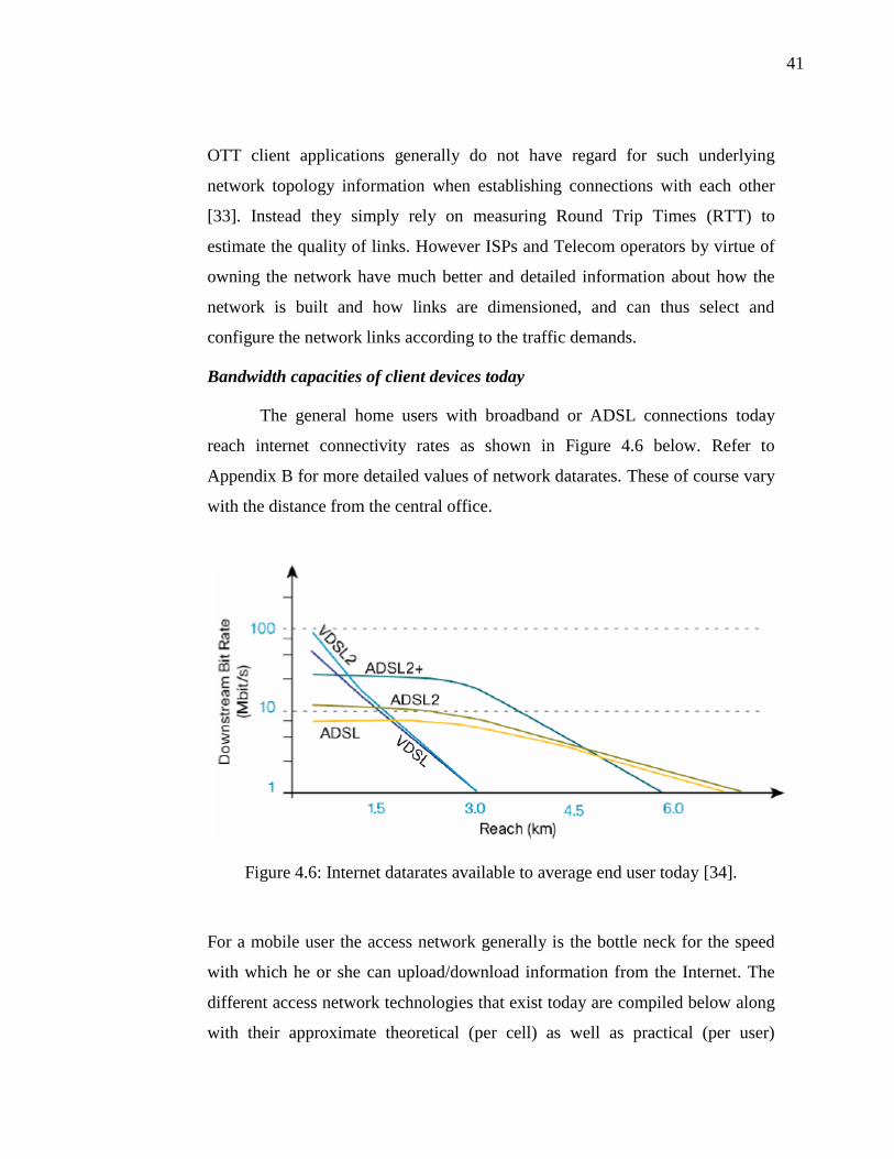
41
OTT client applications generally do not have regard for such underlying
network topology information when establishing connections with each other
[33]. Instead they simply rely on measuring Round Trip Times (RTT) to
estimate the quality of links. However ISPs and Telecom operators by virtue of
owning the network have much better and detailed information about how the
network is built and how links are dimensioned, and can thus select and
configure the network links according to the traffic demands.
Bandwidth capacities of client devices today
The general home users with broadband or ADSL connections today
reach internet connectivity rates as shown in Figure 4.6 below. Refer to
Appendix B for more detailed values of network datarates. These of course vary
with the distance from the central office.
Figure 4.6: Internet datarates available to average end user today [34].
For a mobile user the access network generally is the bottle neck for the speed
with which he or she can upload/download information from the Internet. The
different access network technologies that exist today are compiled below along
with their approximate theoretical (per cell) as well as practical (per user)

42
datarates. The practical per user datarate is always less than the theoretical
datarate because of many factors, some of which as listed below:
a- The available bandwidth in a cell is shared among all the users present in
that cell. This means that as the number of simultaneous users in the cell
increase, the per user datarate decreases.
b- Distance from the base station or access point also plays an important
role in determining the strength of signals reaching the user terminal and
thus determines the experienced datarate.
c- Interference from other devices in the neighborhood might also cause the
datarates to suffer. This is especially true in case of WiFi, which works
in the ISM (industrial, scientific and medical) band. Many other devices
and technologies can also work in the same frequency band.
Theoretical maximum
datarates Practical per user datarates
Technology downstream upstream downstream upstream
UMTS 177Kbps 118Kbps 70-130 Kbps 70-130 Kbps
HSPA 14Mbps 5.8Mbps 1 to 4 Mbps 0.5 to 2 Mbps
LTE 100Mbps 50Mbps 13Mbps 3.8Mbps
Wireless
LAN, WiFi 54Mbps 54Mbps 2 Mbps 512Kbps
Table 4.5: Average bit rates for mobile users using different access technologies
[31][32]
4.4 SUMMARY
In summary, we see that the tasks of mixing and transcoding media streams
from multiple participants in media conferences place stringent requirements on
the computational and bandwidth capabilities of the MCU. This is particularly

43
true for video conferences which support SD or HD video content, since this
adds a lot more data to be processed and transmitted in realtime. When
compared against the potentials of end user terminals available today, it is seen
that even in best case scenarios, client devices struggle to meet the required
processor and bandwidth demands even for small to medium scale conferences.
44
5 MEDIA PROCESSING IN COMMERCIAL
COMMUNICATION NETWORKS
Having gone through the fundamental aspects governing media conferences in
packet switched networks, we now go into details of how media conferences are
really implemented in large scale commercial networks today. The most
challenging aspect in media conferences is to handle multiple media streams
simultaneously in realtime. The introduction of video makes it an even greater
challenge due to the large size and complexity of video packets. We will now
focus on the media processing methods used in two major sectors of
communication networks widely seen today:
Operator Networks
Over the Top (OTT) Networks
5.1 MEDIA PROCESSING IN THE OPERATOR NETWORKS
Operator networks rely on the intelligence and capabilities hosted by the
network. Building on powerful, reliable and redundant systems, these networks
can provide services to large populations of subscribers on a continuous basis.
The same is true for media processing tasks including media transcoding and
media mixing. It is thus logical for operators to follow the centralized media
conferencing architecture, where the entire media processing load is taken up by
specialized servers in the network.
It is also possible that a session spans over multiple operator networks, such as a
conference call where some participants of the conference belongs to network A
and other participants belong to network B. In such cases typically the media
processing and mixing is handled by the network where the conference call
originates.

45
In the following sections, we give an overview of some of the common network
elements in telecom operator networks which are good candidates for providing
media processing support in small to large scale conferences [43].
5.1.1 MEDIA GATEWAYS
Media gateways reside in the network’s media plane, where they act as
intermediate network elements. All media is routed through them. Thus, they
naturally pose a promising place for media transcoding in the network. The
conversions performed by media gateways between different networks range
from voice streams transformations, such as insertion of tones or changing of
the used codecs, to data stream manipulation. Hence, they already have the
needed DSP requirements and processing power that can guarantee realtime
media transcoding and mixing.
5.1.2 SESSION BORDER CONTROLLERS
Session border controllers (SBC) are network elements deployed at the network
edge (user-network interface (UNI) or network-network interface (NNI)). They
primarily serve the purpose of ensuring network security. They monitor both
signaling and media flows into and out of the network and perform a variety of
security related functions, such as network address translation, firewalling or
bandwidth monitoring, to avoid possible bandwidth theft and to enable QoS
provisioning. To fulfill these stringent requirements, the SBCs have typically
fast processors to dissect the packets quickly and rewrite their headers in
realtime.
Since these devices lie at the edge of the network, they also provide a convinient
location for media transcoding/mixing.

46
5.1.3 APPLICATION SERVERS
Application Servers (AS) are standalone processor intensive systems installed in
an operator’s core network specialized for providing specific services such as
presence/location services, Network Address Translator (NAT) traversal
services, Web portals etc. Considering their processing power and the fact that
they can be built specific to the demands of the application, they are optimum
for media processing. One drawback is that application servers are typically
located in the network core and not at the edge of the network. Thus, even if two
users are topologically close to each other in the network, their media streams
will need to be routed all the way to the network core to undergo the required
transformations. We see that in most cases, the location of application servers in
the network plagues them with backhauling problems.
An example of AS is Media Resource Function Processor (MRFP). It is an
application server in IMS domain which sits on the media plane to provide
media mixing and tone generation services to IMS user agents.
5.2 MEDIA PROCESSING IN OTT NETWORKS
The majority of the Over The Top (OTT) services use peer to peer (P2P)
networking as their underlying communication framework. Peer to peer
networks are by definition those which do not have any dedicated clients and
servers in the network. Instead several end systems (or peers) share their
resources together to form an overlay network which can provide the intended
services [42]. This inherently makes the peer to peer systems less reliable as
compared to their centralized (dedicated server oriented) counterparts. The
reason for this stems from the fact that the P2P systems have no control over the
nodes that make up the network. Any node can leave the network without prior
notification, and the P2P system has to adapt to such abrupt changes
dynamically. Also, such systems are impeded by lack of dedicated resources,

47
and instead all the requirements (CPU cycles, memory or bandwidth
requirements) must be taken care of by the end systems themselves.
We take for example Skype [37], a widely used P2P telephony application. The
Skype overlay network consists of two tiers of peers which can be referred to as
nodes and super nodes.
When a skype node A wishes to make a voice or video call to another node say
B, it establishes a TCP signaling connection with B, and then the media can
flow over UDP or TCP. However often the scenario is not that simple, and
either one or both the nodes are behind a NAT. In such scenarios, the caller A
and callee B have to rely on other nodes in the skype network to act as relay
nodes, which would then forward the packets from A to B and vice versa [46]. If
during the call, the relay node disconnects from the skype network, a new relay
node must be dynamically chosen. It is also possible that one node is being used
as a relay by multiple other nodes in same or different simultaneous call
sessions. This means that the relay node would see a lot of random traffic
flowing through it.
Thus we see that the whole network relies on a certain minimum number of
nodes to be ideally available and online simultaneously within the overlay for it
to function properly. More number of online nodes guarantee a better service to
all users while a decrease in nodes in the overlay would result in a lack of
available resources and hence a degradation of service. More detail on the
Skype P2P network is given in section 6.4.2.
Another example is that of internet based P2P Content Distribution Networks
(CDN), such as PPlive [47]. Instead of streaming video or live television
broadcast from some central streaming server(s), the users of the P2P service
distribute the media streams to each other. This means that one peer will act as a
streaming server for many other nodes and will upload the media stream(s) to
them. It has been observed that there can be long delays before streams reach a
peer in such a P2P CDN. The delays have been observed to range from a few

48
seconds to even minutes [48]. Such delays might be acceptable in normal
broadcast viewing, but serve as a challenge when considering interactive TV.
Realtime applications such as video conferencing pose stringent requirements
on end to end delay and processing power of the participating nodes. This makes
it a challenge for peer to peer networks to host such services.
In the following subsections we take a look at the different possibilities and
limitations for video mixing and transcoding with respect to conference
applications in today’s OTT networks.
5.2.1 MESH NETWORK (MULTI-UNICAST)
The simplest solution in terms of architecture of the conference in the absence
of any central conference server is a full mesh network. As discussed previously
in section 3.2.1, in the mesh network every conference participant has a direct
connection with every other participant. Considering the media flow, we see that
a node has to unicast its media stream(s) to all the other conference participants.
This also implies that a node will receive multiple media streams, generally one
from every active participant. Receiving and sending out many media streams
simultaneously is a bandwidth exhaustive process, and considering that video
packets are quite bulky, the bandwidth utilization may hit the upper limit of
many end user connections as the conference grows larger.
Nodes will also have to decode all of the received media streams to be able to
play them. This also adds to the CPU load on the end devices.
5.2.2 SINGLE PEER
Another straight forward media conferencing architecture in the absence of a
central server is that of the end system mixing, where one of the end systems is
nominated to take care of all the transcoding and mixing processing. The end
system mixing model is explained in more detail in section 3.1.2. This model

49
works for smaller conferences, but is not very scalable. Based on our analysis on
the design and requirements of an MCU in chapter 4.3, many of today’s end
systems and user terminals are incapable of handling the task of mixing and
transcoding for good quality video from more than three participants.
Many of the client applications running on peer devices that make up OTT
networks have certain criteria against which an end device is chosen to handle
the media mixing tasks. [46] suggests that Skype, a well-known P2P client,
nominates the mixer on the basis of its downstream/upstream bandwidth and its
processing capabilities as compared to the rest of the peers in the conference. In
addition, elaborate client protocols may enable the role of the media mixing to
be shifted from one peer to another in case a peer with better bandwidth and
processor capabilities joins the conference. The signaling associations may
however remain coupled with one central peer throughout the conference, as
shifting the signaling association from peer to peer might be complex. This
makes such an architecture unreliable and susceptible to complete breakdown in
case the peer acting as the center for the conference leaves the overlay or gets
disconnected [36].
5.2.3 MULTIPLE PEERS (COOPERATIVE MIXING)
The idea of cooperative mixing has been proposed in some publications
[40][57]. The model aims at distributing the task of mixing and transcoding, to
more than one device in the conference. This way multiple peers can pool in
their resources to cumulatively perform the tasks of an MCU. This model can be
seen as a hybrid between completely centralized architecture (where one system
is responsible for all mixing/transcoding tasks), and a completely distributed
architecture (full mesh architecture as described in section 3.2.1). Even though
multiple peers may be contributing their resources for media processing tasks,
the signaling might still be handled by one central peer in the network, which in
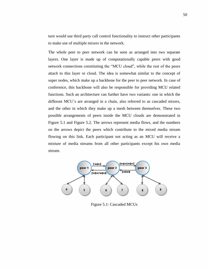
50
turn would use third party call control functionality to instruct other participants
to make use of multiple mixers in the network.
The whole peer to peer network can be seen as arranged into two separate
layers. One layer is made up of computationally capable peers with good
network connections constituting the “MCU cloud”, while the rest of the peers
attach to this layer or cloud. The idea is somewhat similar to the concept of
super nodes, which make up a backbone for the peer to peer network. In case of
conference, this backbone will also be responsible for providing MCU related
functions. Such an architecture can further have two variants: one in which the
different MCU’s are arranged in a chain, also referred to as cascaded mixers,
and the other in which they make up a mesh between themselves. These two
possible arrangements of peers inside the MCU clouds are demonstrated in
Figure 5.1 and Figure 5.2. The arrows represent media flows, and the numbers
on the arrows depict the peers which contribute to the mixed media stream
flowing on this link. Each participant not acting as an MCU will receive a
mixture of media streams from all other participants except his own media
stream.
Figure 5.1: Cascaded MCUs

51
Figure 5.2: MCUs arranged in a mesh
Limitations of cooperative mixing
Both the architectural models have certain limitations. The mesh model adds to
the computational load of the overall conference system. As the number of
cooperating mixing peers increases, they each in turn act as a media source for
the others and thus the system does not scale too well. For the cascaded mixers
architecture, the mixing and transcoding delay becomes the limiting factor, as
each mixer adds a certain latency between the input streams and the output
mixed stream. Thus only a limited number of mixers can be chained together if
the communication needs to be realtime. We will now take a deeper look at
these shortcomings on such cooperating MCU architectures.
Limitations when MCUs are arranged in a mesh
We will first discuss distributing the media mixing/transcoding tasks to multiple
peers arranged in the form of a mesh, as shown in Figure 5.2. This scheme
distributes the load onto multiple peers, but in general this does not mean that
the more peers we add to the so-called “MCU cloud”, the better the performance

52
is going to be. First, it depends on how many capable peers we have in the
network, and even we have ample amount of such peers which can handle the
load of media mixing and transcoding, it does not mean that adding all of them
to the cloud would be the best solution. To understand this concept, we
introduce a metric called “load-per-MCU”, which quantifies how many other
peers are connected to an MCU in a network. Of course the more peers an MCU
has to handle, the more processing cycles it needs.
It should be taken into account that if there are multiple MCUs in the network,
the output of one will act as an input stream to the other so that media streams
from all participants reach every participant. Now consider we have 12 peers
participating in a conference. Considering that we have ample number of
capable peers among them, the following combinations depicted in Figure 5.3
are possible and many more until the system becomes a full mesh network. One
thing to keep in mind is that MCU with more capability can take up large
number of peers, while less capable MCUs will serve smaller number of peers.

53
Figure 5.3: Possible scenarios in which MCUs can be arranged in a mesh
MCUs: 6
Each MCU serves: 6 peers
MCU: 1
MCU serves: 11 peers
MCUs: 2
Each MCU serves: 6 peers
MCUs: 3
Each MCU serves: 5 peers
MCUs: 4
Each MCU serves: 5 peers

54
As can be seen from Figure 5.3, the most optimum load distribution is achieved
with 3 MCUs in the network. Each MCU has to handle 5 peers (out of which 2
are other MCUs). When the number of MCUs increases to four, although the
number of peers served by each MCU remains the same, the number of media
streams flowing through the network increases. This effect is depicted in Figure
5.3. As more MCUs are added, the number of peers served by each MCU starts
to increase.
The lower bound for the number of peers handled by a mixing peer, is therefore
5 peers in 12 member conference. For a normal end system today, handling 5
peers is not an easy task.
Using simple numerical analysis methods, an equation can be derived for
calculating load-per-MCU. The load-per-MCU y, in a conference with N
participants, amongst which x are nominated as cooperating MCUs can be
expressed as
2N
y xx
This represents a parabola. Our intention is to find out the number of MCUs x
that need to cooperate in order to attain the smallest load-per-MCU y in a given
conference. We thus need to calculate the minima of this equation. Although x
and y represent sets of discrete numbers (whole numbers), but if we for the
moment assume them to be continuous, then taking derivative of both sides
2N
d xdy x
dx dx
2
1dy N
dx x
and setting the derivative equal to zero will give us the minima of our parabola

55
21 0
N
x
x N
Since x can not be a decimal number, so we only keep the integer portion of x
(equivalent of flooring x), which suffices as a solution to our problem scenario.
If we put this value of x back into our original equation, it will give us the
minimum value of load-per-MCU (number of peers served by each MCU) for a
conference with N participants as:
2 2y N
Where we again keep only the integer part of y. To summarize, for a conference
involving N participants, where multiple participants can act as cooperating
MCUs arranged in a mesh, the load-per-MCU can not be less than 2 2N in
ideal cases. This shows that as the conferences grow bigger, so does the
minimum bound of peers per MCU and this minimum limit is still quite high to
cope with for the average client devices today.
Limitations of Cascaded MCUs:
We will now highlight some limitations of cascaded mixing model [40]. Media
mixing involves complex processes like decoding, resizing and encoding the
video frames and it normally takes some time for the MCU to accomplish these
tasks. This is especially true for complex codecs such as the H.264, which
provide high network efficiency but in turn depend on elaborate mathematical
computations during the decoding and encoding process. Depending on the CPU
power and capability, the delay can vary from a few milliseconds to couple of
hundred milliseconds. Values from Texas Instruments [63] suggest that current
media processing DSP boards add about 25ms of delay during decoding process
and 30ms of delay during encoding 720p H264 video stream. This means that
neglecting all other transforms applied to the video during mixing and

56
transcoding process, just the encoding and decoding at one mixer would add
about 55ms of delay.
As we have already pointed out, video conferencing is a highly delay sensitive
application, and while other variants of video streaming such as TV broadcasts
can tolerate delays in terms of seconds (due to receive buffer), video
conferencing can only tolerate up to 200ms of one way mouth-to-ear delay to
ensure satisfactory end user experience [64]. A delay bigger than this renders
the interactivity in the video stream suffering badly and the user experience can
drop.
A delay constraint of around 200ms means that we could have at maximum four
MCUs in one chain, and adding a fifth one will render the video conference
unusable for realtime communication purposes. This is because the input to one
cascaded mixer depends on the output from a preceding mixer, thus the mixers
make up a queue where the delays are simply added from end to end.
One way to mitigate this problem would be to select a codec which requires
minimal processing time while decoding and encoding, but this in turn means
that the codec will not be bandwidth efficient, and thus can not be used over
typical networks of today.
5.2.4 CONCLUSIONS ON MEDIA PROCESSING IN OTT
NETWORKS
We therefore see that in OTT networks, having a full mesh network has its
limitations in terms of bandwidth and CPU requirements on end devices. The
case where a single peer is used as an MCU suffers from unreliability issues.
Similar limitations apply to both architectures of cooperative
transcoding/mixing. In some conferences, the peers might be arranged as a
combination of both architectures, i.e. some portion of the conference makes a
mesh, while the other portion will have the MCUs chained together, but the
optimization bounds are still narrow.

57
In addition to the above mentioned limitations of cooperative mixing and
transcoding, peer to peer overlay networks also suffer from a number of other
drawbacks [65] which make them unsuitable for such cooperative models where
everything has to be accomplished in realtime. Some of these additional
limitations of P2P networks are mentioned below in brief:
Managing peer dynamicity:
In P2P networks, peers can join and leave the overlay dynamically and
without any prior warnings, or their bandwidth might suddenly change. Such
behavior is even more common with mobile peers. A general problem with P2P
streaming applications is that several intermediate nodes might be used to
forward a stream from the source to the destination nodes. In case any of the
intermediate node disconnects, the network must adapt quickly to construct a
new delivery path. Several time critical packets might get delayed, lost or
dropped during such a path re-construction.
Incentives for participation:
P2P systems are built of the concept of sharing resources. However it
has been observed that peers tend to get greedy, and while they use a lot of
resources from other peers, they do not so much want to let others use their
resources. Such peers are termed as “free riders” [66]. In our scenario of
cooperative mixing, there might be many peers who would intentionally avoid
being selected as the mixer or transcoder. If the number of such peers grows, the
system becomes more like a client server architecture where the number of
clients simply outweighs the server capacity. Several proposals have been
suggested [66] for providing incentives to peers in P2P networks such as Virtual
Payments, Reputation based systems, Reciprocity based systems etc but it still
remains an area open for research.
Security Challenges:
In P2P systems, who to trust with private information is always a
question. In the case of conversational P2P systems, if the processing of media

58
streams remains within the participants of the on-going session, it is deemed
secure up to some level. But in cases where the processing (mixing/transcoding)
demands can not be met by the nodes participating in the session, the processing
demands might get pushed to a peer outside the (conference) session, and that
opens a lot of trust issues. We cover the security issues in more detail in section
7.
This means that some level of support for media mixing and transcoding should
ideally exist inside the network, and the idea of using end devices to handle such
an intensive task does not scale too well. However, as discussed before, P2P
networks are built on the idea that the individual peers would pool in their
resources handle all the tasks, and as such do not have any in-network hosted
resources.
This opens grounds for a possible cooperation between OTT service providers
and telecom operators, where OTT users utilize the resources from operator
network, and, the telco operators in turn get a better user base and coverage by
expanding their services into P2P networks.
5.3 SUMMARY
OTT service providers and conventional telecom operators, both have different
approaches in how media conferences are setup in their networks. Different
conference architectures are preferred depending upon the resources available.
But in general it is seen that operator networks prefer to host conferences on
specialized conference servers inside the network. This corresponds to
centralized conference architectures. The signaling, control and media
processing requirements are handled by reliable and powerful nodes which have
very strict availability criteria. Media processing demands can be handled at the
edge of the network by nodes such as media gateways, session border
controllers or in the core by specialized application servers. However heavy
investment is required to build up and maintain such networks.

59
On the other hand OTT networks require little or no investment as they are
based on P2P concepts. However generally this means that there is a lack of
powerful nodes in the network. Thus media conferences are often established
such that responsibilities are shared or distributed between various peers. This
can involve multicasting, multi-unicasting or cooperative mixing models.
However such models have their own limitations and in the absence of capable
peers these models don't scale too well for large conference sessions. In addition
there are other inherent limitations in P2P networks such as managing peer
dynamicity, offering incentives to participate and share resources in the network
and ensuring security of information.
Thus we see that both these domains are fundamentally different and these
differences are also quite prominent when it comes to media conferences. In the
next section, we shall see if it's possible for these both domains to benefit by
cooperating with each other and how such cooperation can be achieved.

60
6 COOPERATION BETWEEN OTT AND OPERATOR
NETWORKS
Traditionally Over The Top (OTT) service providers and carrier network
operators have been on competing terms [4]. The network operators invest
heavily in planning, developing and maintaining their networks and thus they
expect that any service provided to an end user through their network, should
generate direct revenue for the operator. Telecom operators have even gone the
distance to “lock” the user terminal if the user wishes to install or use a service
other than the ones provided by the operator itself. In short, the operators
believe in “customer ownership”, meaning that their customers will use only
their services. The operator can then use methods such as service aware
charging to bill the customer for the service rather than the network bandwidth
used. A good network means bigger customer base which generates more
revenue.
But this ideal network ecosystem is disturbed when third party companies such
as Google, Amazon, Skype etc start providing end users with multitudes of
services which are not hosted by the network operator but instead by the free
internet. The operator’s customer ownership is lost. The operator can no longer
bill the customers for the services they use but instead can only charge for the
bandwidth utilization in the network.
While the telecom operators come up with schemes to restrict access to third
party services on their networks, the OTT industry fights for net neutrality,
meaning that all end users should have the right to access the internet with
freedom. Clearly this tussle for customer ownership will continue unless
avenues for cooperation are sought. Telco 2.0 [25][4] is one such effort to
highlight possible terms on which network operators and over the top service
providers can co-exist, while offering value for each other.
Another aspect that also plays a role in shaping the ecosystem of the
communications industry is the competition between various telecom operators.

61
So far we have only referred to the operators as one united entity, however
operators also compete with each other. This competition is driven by the notion
that better services and lower rates attract a larger customer base. For example
some operator might offer network based video recording service during video
conference sessions at little extra cost thus attracting more customers to its
network. The question thus arises how this inter operator competition will affect
their cooperative agreements with OTT service providers. We believe that
operators will continue to compete with each other and indeed this competition
will also be a major driving factor in deciding which operator enters cooperation
with which OTT provider. Having a partnering OTT service provider can be
seen as an additional service that the operator can offer to its customers (such
add-on services are also sometimes referred to as Value Added Services (VAS)
[51] in teleco domains). In fact such cooperations are already beginning to take
shape such as:
a) Spotify [52] online music service is being budled with 3 UK [53] service
plans [51].
b) Alhough in its early stages, another example is the initiative of
cooperation between Ericsson [55] and Akamai [54][26]. Ericsson being
a mobile network vendor and Akamai being a well known content
delivery service provider can together target content providers with
optimized content delivery (video, web content, audio etc) to mobile
users. The content provider will pay Akamai for improved user
experience. Revenue from content providers will then be shared among
three players including Akamai, Ericsson and the mobile operator whose
network is used for mobile content delivery.
c) Japanese mobile operator NTT Docomo [56] launched its i-mode service
to enable collaboration with content providers. It also features a billing
system based on revenue sharing between Docomo and the listed content
providers. Docomo claims about the i-mode service: “We have been
promoting beneficial alliances with a variety of international partners,

62
including content providers, overseas operators, ISPs, software
developers and manufacturers” [56].
In the chapters below, we assess why and more importantly how such
cooperative agreements between network operators and OTT service providers
can be established. We present video conferencing and media transcoding as
example applications where telecom operators and OTT service providers can
cooperate.
6.1 MOTIVATION FOR COOPERATION
Before any cooperative agreements can be reached, it must be clarified what
business value do such agreements hold for both the market players and also
what benefits should the end user expect. The following factors are seen to be a
driving force behind ensuring cooperation between the OTT industry and
network operators.
By interworking with OTT service providers, operators can increase
their coverage to parts of the network which do not directly fall under
the operator’s domain, such as private LANs or mobile ad-hoc networks.
In such cases, a P2P network may be used as an access network to
connect a user to the operator’s core. This will allow the subscriber to
use his or her home network’s services (which are otherwise buried
inside the operator’s “walled-garden”) such as voice-mail while not
within direct coverage of the operator’s network. Also any incoming
calls to his URI can be routed through to him or her using the overlay
P2P network.
Peers registered in the OTT domain can benefit from services hosted in
the operator network on need basis, such as using relay servers or
transcoding servers.

63
OTT applications involving real time delivery of packets can get better
QoS guarantees from the underlying operator network, thus considerably
improving the end user experience.
Allowing users of different domains to share data, messages and
converse with each other will create a ubiquitous communication
environment. The operator network can also act as a bridge between
different OTT networks, which otherwise do not have direct interfaces
with each other.
OTT applications running on client devices generally do not have regard
for detailed network topology, and they usually calculate their network
routes based on application layer methods such as taking Round Trip
Time (RTT) measurements. Such complete isolation of application layer
from network layer routing logic can cause un-optimized application
layer routing. This leads to congestion or use of network links which are
not dimensioned to carry large amounts of traffic. Since network
operators dimension their networks, they have first hand capacity
planning and network routing information. Unfortunately, operators do
not know how the OTT applications will use their network and react to
delay or congestion. If the network layer information is made available
to the client application, the use of network bandwidth can be greatly
optimized [70]. This also calls for a cooperation between the network
operators and OTT service providers [71].
6.2 TECHNICAL REQUIREMENTS FOR INTERWORKING
BETWEEN OTT AND OPERATOR NETWORKS
The first step before any cooperation between operators and OTT service
providers can flourish is to make sure that both domains can communicate and
understand each other. The P2P networks generally consist of small user
terminals, which are privately connected over some client protocol to other

64
peers. Thus, they construct an overlay network, where they can easily route and
exchange information from other peers within the overlay, but seldom
communicate with external systems. To integrate these P2P networks with
operator networks is not very straight forward. Certain conditions need to be
met before messages can start to flow between both domains and applications
can work normally [44][45]. We take a look at these requirements for inter-
working in the subsections below.
6.2.1 PROXY PEERS
As discussed earlier, most OTT networks are based on P2P overlay concepts.
Various peers can communicate with each other using identification and routing
information stored locally, centrally or in a distributed fashion inside the overlay
[66]. This information allows peer within the overlay to communicate with each
other. However, very few of these peers have publically routable IP addresses.
This means that a user who is a part of an overlay network cannot be directly
accessed from external users unless some method is devised by which packets
can be routed to and from this user and external users. One proposed solution to
this problem is to use proxy peers [44].
Some peer to peer networks (such as Skype) have the concept of distributing the
routing and lookup responsibilities unequally amongst peers [46]. The more
dynamic peers, which attach and detach frequently from the overlay, are called
nodes, while other peers, which are considerably more stable and have better
CPU and network capacity, are called super-nodes. These super-nodes act as the
backbone of the overlay to which all other nodes are connected.

65
Figure 6.1: Example Skype network topology [46]
In a similar way, some of these super-nodes, which have publically routable IP
addresses, can act as proxy peers for the overlay. The proxy peer will act as a
gateway for inter-domain communication, i.e. when a session has to be
established between an internal peer and an external peer. The external peer
might belong to some other overlay network or some conventional operator
based network. Any information that has to come from an external node to a
node inside the overlay will pass through the proxy peer, and the same route can
be followed in the reverse direction. Ideally a number of proxy peers can work
together to make up a proxy layer inside the overlay with different proxy peers
distributed in different portions of the network.
The criteria on the basis of which a proxy peer gets chosen or elected from
within a P2P network include these:
Online time i.e. the time for which the node has been online and part of
the overlay
66
Network bandwidth
CPU capability
Publically accessible IP address
Once a proxy peer or collection of proxy peers is chosen, they will also be
assigned a Fully Qualified Domain Name (FQDN) in the Domain Name System
(DNS), which would represent the overlay network to which they belong. Due
to the dynamic nature of overlay networks, the proxy peer might also detach
from the network and instead a new proxy peer might need to be nominated.
Hence Dynamic DNS should be used to enable the records to be dynamically
updated to point to the current proxy peer(s).
Now lets look at an example scenario where a user of an external network
(sip:[email protected]) wants to establish a session with a user inside an
overlay (sip:[email protected]). In this case, Alice follows the procedures for
establishing sessions between two distinct network domains. Alice first
formulates a session establishment request with the destination as the URI of
Bob. This request is routed to the outbound proxy in the “operator.com”
network (sip:[email protected]). This proxy server needs to find where to
forward the session establishment request. Thus it first follows the DNS
procedures to locate the address corresponding to the domain of the destination
URI. In effect it queries the DNS for the IP address corresponding to the FQDN
of the overlay (p2p.org). The DNS response contains the IP address of one of
the proxy peers belonging to the overlay network (the DNS can also load
balance between multiple proxy peers). The proxy server in the “operator.com”
network then forwards the request to the address it received from the DNS. This
request gets routed to the overlay’s proxy peer (sip:[email protected]). The
proxy peer on receipt of this request extracts the identifier of the exact peer
(Bob), for which the request is intended. It then uses the overlay client protocol
to locate this peer, and once found, it forwards the request to the target peer. The
receiving peer then either replies directly to the originating external node if
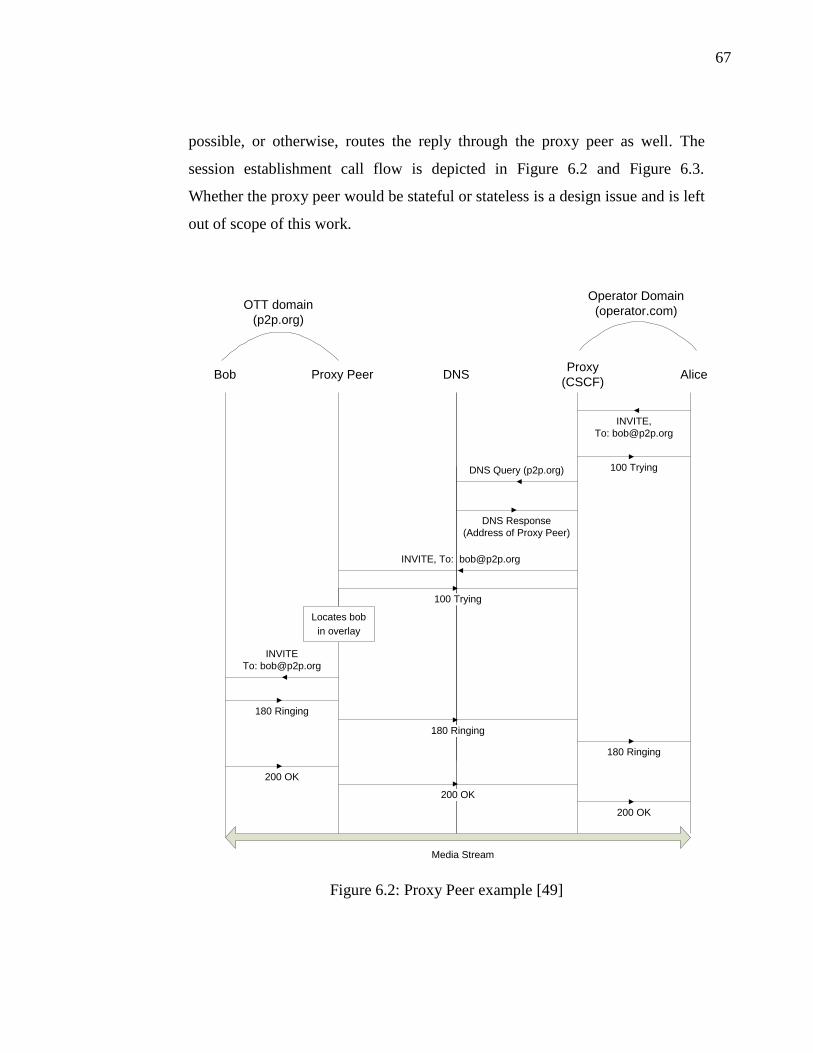
67
possible, or otherwise, routes the reply through the proxy peer as well. The
session establishment call flow is depicted in Figure 6.2 and Figure 6.3.
Whether the proxy peer would be stateful or stateless is a design issue and is left
out of scope of this work.
INVITE
INVITE, To: [email protected]
Bob Proxy PeerProxy
(CSCF)AliceDNS
DNS Query (p2p.org)
DNS Response
(Address of Proxy Peer)
OTT domain
(p2p.org)
Operator Domain
(operator.com)
180 Ringing
100 Trying
Media Stream
INVITE,
100 Trying
Locates bob
in overlay
180 Ringing
180 Ringing
200 OK
200 OK
200 OK
Figure 6.2: Proxy Peer example [49]

68
Using this methodology, different overlays can be connected with each
other. Further more, the P2P overlay would be able to interwork with
conventional networks as well. This is especially straight forward for the
case where the P2P network nodes use P2PSIP as the signaling protocol, and
the conventional network uses SIP as the signaling protocol (such as IMS).
In case of incoming requests, location of nodes is made possible by the
proxy peer using the overlay client protocol, after which the session
proceeds like a normal SIP based session through a SIP proxy.
Figure 6.3: Proxy peer receives external call and routes to internal peer
6.2.2 SERVICE DISCOVERY MECHANISMS
P2P networks are based on the idea of pooling together resources from multiple
peers and then working in collaboration to achieve the tasks that the
immediately local peers might not be able to accomplish. Different peers
offering different services are highly distributed inside the overlay. The first step
inherent to every P2P network is the resource discovery within the overlay.
The generic mechanism for service discovery is to use the a service discovery
protocol to send out queries for a certain service. The service location

69
information may be stored centrally on some directory node(s), it may exist in a
distributed fashion within the overlay or it may exist only locally on the nodes
offering a specific service. If a directory or registrar node exists in the network,
the peers can simply unicast their service queries to this node. This ofcourse is
possible provided that the querying node knows about the directory node,
otherwise this may involve a service discovery for the directory node itself. In
the absence of such a directory node, the service query may be looked up in the
overlay’s DHT, multicasted or flooded through the network using some other
scheme. On receipt of such a query, if a node hosts the required service or
knows a location where the service is hosted, it will respond to the querying
node. Otherwise it may discard or forward the original query depending upon
the protocol specifications. An example of such a service discovery protocol is
the Service Location Protocol (SLP) [50].
For the purpose of explanation, we assume that the video mixing and
transcoding service is identified by the name ‘mcu’ in the overlay. A peer
wishing to establish a conference or in need of transcoding services will send
out the mcuQuery request in the network. This request will be routed through
the overlay over many peers until some peers, that provide such a service,
answer with their identities in the mcuResponse(peer identifier) message. The
originator of the request will then determine which peer to choose from the
available responses according to metrics discussed below. Once chosen, the
request originator will then establish a session with this peer.
Now consider the scenario where an mcuQuery reaches a proxy peer. Since the
overlay’s client protocol is not necessarily understood by nodes that lie outside
the overlay, this mcuQuery will not be forwarded out from the proxy peer. Even
if the proxy peer itself does not provide the mcu service, it has information
(address/URI) about the media processing server(s) in an external domain
(which can be an operator based network). The proxy peer will then reply with
the mcuResponse(URI of the external mcu) to the originator of the request. Thus

70
the proxy peer acts as an interface between the overlay and the external
networks also during the service discovery phase.
If the originator of the request receives multiple response messages to its query
(which it will in case of a large enough overlay network), there must be some
mechanism and criteria, on the basis of which the best one among the various
responses is chosen for the session. To facilitate the choice, metrics such as the
ones defined below could be included in the response.
available CPU cycles
available network bandwidth
cost of usage
The above defined scenario assumes that the proxy-peers will have pre-shared
knowledge about the addresses of media processing units in external networks.
The question still remains, how such information will reach the proxy peers.
One of the requirements for enabling such an external use of services hosted
inside the conventional operator network is to announce or publish their
addresses/URIs in some directory, from where peers can look up this service
and then try to contact the specified network hosting this service. There can be
multiple models depending upon what level of availability is required. The
operator hosting MCU services can provide the address where the MCU nodes
can be accessed to the OTT service provider under agreed contracts. The OTT
service provider can then float this information in the overlay. Proxy peers can
then cache this information if required.
Another model based on more open availability can be to add records
corresponding to MCUs and conference servers in the public DNS, for example
sip:[email protected] and sip:[email protected]. An external user such as a proxy peer
from a P2P network querying the DNS for [email protected] would then receive the
publically routable address of the network proxy (which is the Call Session
Control Function (CSCF) in case of IMS). The user can then send the request
71
for MCU to this address, where the CSCF after checking the network’s service
access policy will forward it to the available MCU inside the network.
The proxy peer can also cache the DNS records for MCUs temporarily to avoid
having to send frequent requests to the DNS. It can periodically verify that the
records are up to date with the DNS.
6.2.3 SECURITY POLICIES IN OPERATOR NETWORK
The interworking with external P2P networks and OTT applications would
require commercial telecommunication network operators to modify the security
policies governing their networks, so that external users can access for example
relay servers or MCU servers inside their network. This can also be thought of
as the operator opening external network interfaces or Application
Programmable Interfaces (APIs) that can be used by third party applications to
gain access to the network’s internal assets [51]. One way to do this would be to
add the URIs of certain known proxy-peers in the operator network firewall’s
whitelist. In such cases, the local MCU of an operator would act as a back-to-
back user agent in terms of SIP. This means that it would accept connections
from outside the network and create further connections to other users (inside
the network or outside). Certain authentication and authorization schemes to
allow users not only registered within the home network but also in external
networks to make use of the intelligence hosted within the network have to be
devised. Such schemes will be covered in Chapter 7 on security considerations.
6.2.4 SIGNALING GATEWAY
In cases where the two interoperating networks or domains use different
signaling protocols, some protocol translation mechanism would need to be used
at their adjoining interfaces. Such functionality is usually provided by signaling
gateways. Examples of such a signaling protocol conversion can be H.323 to
SIP and vice versa.
72
6.3 CALL CASES
The following call scenarios serve as example cases with all signaling based on
SIP. One of the reasons for choosing this protocol here is that it can be
implemented both in P2P based OTT networks, in which case it is referred to as
P2PSIP, and in the conventional operator networks such as IMS. However, any
other signaling protocol, which has the general capability to establish multiparty
calls, should work in call scenarios similar to the ones highlighted below.
In the following scenarios, there are two network domains. The OTT network
has a domain name of p2psip.org, while the operator network is named as
ims.org. The OTT domain has a proxy peer reachable via Sip URI
sip:[email protected]. Alice (sip:[email protected]) and Bob
(sip:[email protected]) are two users in the OTT network. Darth
(sip:[email protected]) is a user in another OTT network (p2psip-b.org) with
proxy peer reachable via sip:[email protected]. Carol (sip:[email protected]) is
a user registered in the operator domain. Since it is an IMS network, Carol uses
a CSCF node (sip:[email protected]) as a proxy server to route her signaling
messages to other users or servers. The IMS network also has a conference
server (sip:[email protected]), which can handle both signaling and media planes
for conference sessions.
6.3.1 ESTABLISHING A CONFERENCE
Alice wants to establish a video conference with her friends. Her friends are
distributed in different OTT networks (logged into their different client
applications), and some are in the operator network.
1. Alice uses her overlay’s service discovery mechanisms to locate an MCU,
which can handle the conference’s signaling and media mixing/processing
requirements.

73
As discussed in chapter 6.2.2, at the end of the service discovery phase, Alice
receives some replies and chooses to use the MCU hosted inside the operator
network (sip:[email protected]).
2. Alice dials into the MCU (through the proxy peer in her overlay). The SIP
Invite from Alice contains the URIs of all participants she wishes to invite to the
conference session. This can be done using the recipient-list procedure as
defined in [35]. This invite message will also contain the SDP which defines the
media stream parameters from the session initiator that is Alice.
3. The proxy peer in Alice’s domain resolves the URI of the MCU which then
points to the IMS CSCF node. The proxy peer forwards the Invite request to the
CSCF.
4. The CSCF will act as a proxy, and may choose to authenticate Alice. This can
be based upon the SIP usage of HTTP digest authentication mechanism [75].
The use and distribution of authentication credentials is discussed further in
chapter 6.4.2.
5. Once the authentication is complete, the CSCF forwards the Invite to the
MCU. On receipt of the Invite message the MCU will start inviting the
requested participants to the conference session. During invitation phase, the
media attributes will be negotiated with each participant separately.
6. To invite a user outside its domain, for example Darth, the MCU will send a
query to DNS through its local proxy (P-CSCF) to resolve the domain name of
p2psip-b.org.
In response, the DNS will provide the public address of the proxy@p2psip-
b.org.
7. The MCU will then send the SIP invite request to the proxy peer which will
use the P2P client protocol to locate Darth within the overlay network.

74
8. Once the proxy peer has located Darth, it would forward the SIP Invite to the
him. Otherwise, if Darth can not be located or is offline/disconnected, a 404
(Not Found) response will be sent back from the proxy peer to the MCU.
MCU Query
MCU Respoce
([email protected], ...)
INVITE
(contains recipient list)
INVITE, To: [email protected] (contains recipient list)
Alice Proxy PeerProxy
(CSCF)MCUDNS
DNS Query (ims.org)
DNS Response
(Address of CSCF)
407 (Proxy Authentication Required)
INVITE (forwarded)
200 OK
INVITE
(contains recipient list)
OTT domain
(p2psip.org)
Operator Domain
(ims.org)
407
INVITE
(contains recipient list)
(with valid credentials)
200 OK200 OK
100 Trying
100 Trying100 Trying
Chooses one
MCU
Starts sending out
invites to other
participants
Media Stream
Figure 6.4: OTT domain user establishes a conference session using MCU in the
operator domain

75
This call scenario is depicted in the Figure 6.4 and Figure 6.5. Figure 6.4 shows
the first phase of the conference setup, where Alice locates and connects to the
operator’s MCU. Figure 6.5 shows the second phase, where on the basis of the
recipient list included in the INVITE message from Alice, the MCU starts
locating and inviting other participants to the conference.
INVITE
INVITE To: [email protected]
Darth Proxy PeerProxy
(CSCF)MCUDNS
DNS Query
(p2psip-b.org)
DNS Response
(Address of Proxy Peer)
180 Ringing
INVITE
OTT domain
(p2psip-b.org)
Operator Domain
(ims.org)
180 Ringing 180 Ringing
100 Trying
100 Trying
Locates
Darth within
the overlay
Media Stream
200 OK 200 OK 200 OK
100 Trying
Figure 6.5: MCU in the operator network invites OTT users in a conference

76
6.3.2 REQUESTING A TRANSCODER IN A POINT TO POINT CALL
In some cases, it might be desired to modify the media stream in some
way before it is played back to the user. For example, in cases involving users
with hearing impairments, it might be necessary to add text overlay on the video
stream containing textual subtitles of the speech [76].
In SIP, there are two prominent models for adding a transcoder [77] into
a session, namely third party call control [79] and Conference bridge
transcoding model [78]. Here we discuss the latter.
Consider a peer Bob (sip:[email protected]) tries to establish a session
with another peer Alice (sip:[email protected]) in a P2P network. The callee
(Alice), on receipt of the SDP, discovers that it would like to receive the media
in a modified format (due to network, device or other limitations as discussed
above). Alice would send out a request into the overlay to locate any node
offering the desired transcoding services. Using service discovery mechanisms
as described in [57], Alice would send out the TranscoderQuery(Service)
messages, which will be answered by TranscoderQueryHit(bandwidth, CPU) by
the peers willing to offer this service. In order to allow discovery of services that
lie outside the overlay, the proxy peer will act as an intermediate party. When
the TranscoderQuery(Service) message reaches the proxy peer, it will look into
its cache and reply with a TranscoderQueryHit pointing to the transcoder(s)
hosted in an external domain, such as an operator network (the cache in proxy
peer can be populated gradually with time). Alice would then use her selection
algorithm to choose one of the available transcoders. Once Alice has made the
decision to add this external transcoder into the call path, she would send back a
302 (Temporarily Moved) response to Bob and include the chosen transcoder’s
address in the Contact header field of the response message. Bob would then
establish a connection with the transcoder and in the INVITE request include the
desired callee’s (Alice) address as the recipient-list. The transcoder can use the

77
same authentication methods as discussed in chapter 6.3.1. Once authentication
is complete, the transcoder would send a separate INVITE to Alice.
For the rest of the session, the transcoder will act as a B2BUA (back-to-back
user agent). As shown in Figure 6.6, the media stream from Alice would
terminate on the transcoder and after required modifications will be forwarded
to Bob. Same would happen in the other direction.
INVITE
Recipient list: [email protected]
Media Stream
200 OK
183 Session Progress
INVITE To: [email protected]
302 Moved Temporarily
Contact: [email protected]
ACK
INVITE
Negotiates media
attributes
Negotiates media
attributes
ACK
200 OK
ACK
Figure 6.6: Transcoder from an operator domain is used to resolve media
incompatibilities in a point to point call between two OTT users
78
6.3.3 REQUESTING A TRANSCODER IN A MEDIA STREAMING
SESSION:
Samanta et. Al. [58] list some of the possible scenarios where
transcoding may be required in video streaming sessions. These scenarios
include switching client devices during a media session, wireless network
bandwidth fluctuations and varying content access patterns.
Media streaming sessions such as mobile TV generally involve many
clients connecting simultaneously to the same content source, such as a media
streaming server. These clients may have heterogeneous media capabilities, for
example in terms of video, some clients may want to view video in a larger
resolution while other clients might not be able to display a large resolution
video and thus require a down scaled version of the same video content. Thus
the content may need to be adapted according to the needs to various clients.
Content Distribution Networks (CDNs) typically deal with such client
heterogeneity problems in different architectures which can be classified into
two broad categories [59]: 1) Static content adaptation, and 2) Dynamic content
adaptation. Static adaptation means that different versions of the same content
are prepared and placed on the server. When a device requests the content, the
version which matches the device requirements most closely is delivered to it.
However, practical experience shows that such architectures come with some
memory and I/O overhead [59] and given the growing number of different client
devices it might not be practically possible to maintain a pre-adapted version of
the content for each type of device. Thus in many cases, CDNs have to resort to
dynamic adaptation, which means that a transcoder converts the media to the
required format at run time when a demand arrives.
Also in mobile communication scenarios, the network conditions are
often hard to predict. Due to the mobile nature of the user terminal, the network
conditions can vary in terms of bandwidth, end to end delay etc. Mostly such
changes are associated with the variance in the radio access network being used
by the user terminal. In such cases one possible solution is to utilize a

79
transrating function which can adapt the media stream according to the network
conditions on the fly.
Dynamic content adaptation (we refer to it as transcoding from here
onwards) can be accomplished at the media server but it may add considerable
computational burden on the streaming server because mobile clients often
require individually customized transcoding [60].
CDNs based on P2P networking concepts often distribute transcoding
and content adaptation responsibilities to other peers in the network which are
willing to share their resources for such tasks [60]. However the success of such
schemes depends on the availability of resourceful peers in the network, and
since transcoding in general and specially video transcoding is a CPU intensive
task and random peers in the P2P network might not be willing to offer their
resources without proper incentives.
Thus whether the OTT media streaming service is P2P based or server
oriented, mobile clients can benefit from transcoding support from the mobile
network. In such cases, a transcoding function can be activated on a proxy node
which connects the mobile client to the streaming server. The proxy node will
receive unmodified content from the server and will adapt it to the requirements
of the mobile client at run time. Such a transcoder, if placed at the edge of the
radio network and mobile core network will also serve as an ideal location for
transrating functions to counter the bandwidth and speed fluctuations in the
wireless network. This is depicted in figure 6.7, which shows that mobile clients
stream the video from a media server on the internet. This media stream is
delivered over the top of the mobile network. The mobile network is only used
to enable transport of packets between the server and the client device. However
since the video packets are going to traverse through proxies and gateways in
the mobile network anyways, these proxy nodes can serve as good candidates
for providing transcoding support if required.

80
Figure 6.7: Example architecture for providing network hosted transcoding
support in media streaming sessions involving mobile clients [61]
Figure 6.8 shows how such transcoding functions can be invoked in a media
streaming session between a mobile client and a media streaming server on the
internet. We make use of SIP as the signaling protocol for our example. The call
flow is based on SIP third party call control functionality [39][79]. Suppose the
client wants to receive one media stream from the server. The client initially
sends an INVITE request to the server without any SDP offer. This results in the
server generating a 200 OK response with an SDP offer (SDP S). The client on
discovering that it can not support the media attributes offered by the server,
decides to include a transcoder in the session. It then sends an ACK to the server
containing 0.0.0.0 as the connection address, thus black holing the media stream
[62]. The client will then generate an INVITE request to the transcoder. This
INVITE will have an SDP message (SDP S+C) containing the earlier offer from
the server and the clients own SDP offer. The transcoder will accept both media
streams choosing one of the offered media formats from the server, and one
from the client. The transcoder will send back a 200 OK response with an SDP
answer (SDP TS+TC). This SDP among other things will also contain the
transport address where the transcoder wants to receive media stream from the
server. From this SDP, the client will tear away the portion which concerns with
the server (SDP TS) and send it to the server in a RE-INVITE message. The

81
server will accept the SDP offer and respond with a 200 OK containing an SDP
answer (SDP S). Once the negotiation is complete, the client will send an ACK
to the server and the transcoder. After this the media can start to flow from the
server to the transcoder, where it will be adapted for the client device and then
forwarded to the client.
Since this scenario involves unidirectional media flows, the SDP from client
will contain attributes of the type ‘a=recvonly’ and the server’s SDP will contain
attribute ‘a=sendonly’ [62].
INVITE (no SDP)
200 OK (SDP offer ”S”)
ACK (SDP Black Holed)
REINVITE (SDP offer ”TS”)
Client
Transcoder
Server
INVITE (SDP offer: ”S + C”)
200 OK (SDP answer ”S”)
ACK
200 OK
(SDP answer ”TS + TC”)
Media Stream
ACK
Transcoded Media Stream
Figure 6.8: Invoking a transcoder in a media streaming session using SIP third
party call control functions.

82
The discussed calls scenarios present only a few frontiers where we can enable
cooperation between the operator domains and the OTT services. This
cooperation can be extended to cover many other scenarios as well given the
proper technical and business ecosystem.
6.4 CONTRACTUAL CHALLENGES IN CASE OF INTER
OPERATION BETWEEN OTT AND OPERATOR DOMAINS
Earlier we pointed out the technical feasibility of a cooperation and inter-
working of over the top networks with operator based networks for providing
better services to end users. However, it must be kept in mind that these two
network domains differ greatly in their business models. While the operator
networks aim at charging end users for the services they use from the network,
the OTT service providers generally provide services free of charge or at a
nominal cost to the end user. Thus, enabling inter-working between these two
differing domains is not just a technical issue but a business feat as well.
In collaborative agreements and business ventures, both players have to come up
with some revenue sharing model which promises sustainable business
cooperation. Telecom operators invest heavily in their networks and thus expect
every user benefiting from the services hosted in their network to contribute to
the generation of revenue in one form or the other. The operator keeps track of
the services used by the users registered in the own domain by maintaining
databases coupled with the registration servers. For example in GSM networks,
this information is kept inside the Service Data Function, which is a part of the
Intelligent Network. Charging logic is then applied to the service usage records
maintained in such databases.
The existence of standard user registration procedures and pre-defined interfaces
allows different operators to interwork. While the user might be roaming in any
network, the service usage data is being collected by the visited network against

83
a temporary identity assigned to the visiting user. The visited network then
charges the home network for the services used by its user.
OTT services are generally provided at minimal or no cost to the end user. This
is so because OTT service providers generally do not invest to maintain
elaborate networks. With minimal investment, OTT services do not have to rely
on extensive billing of their users to generate profit, but instead employ
advertisement based revenue generation models.
The first step before a user can be charged or billed for service usage is to
authenticate the user against some valid credentials. It is easy for a telecom
network operator to bill its users because every user is registered against a valid
identity and is authenticated and authorized by the network. However, OTT
applications generally do not have such stringent authentication mechanisms.
Thus, to enable inter-operation, there must be mechanisms in place inside the
operator domain to authenticate an external user so he or she can be charged for
service usage. Technically, there are solutions to such authentication paradigms
but whether such solutions fit into the business models or not is a question we
explore in the following sub sections.
To understand the potential avenues for authentication of users, we first study
the authentication mechanisms employed by operator networks and those
adopted by the OTT service providers, then highlight areas where possible inter-
operation is possible.
6.4.1 AUTHENTICATION OF USERS IN OPERATOR NETWORKS
The authentication mechanism in most of the operator based networks (GSM,
3G, IMS etc) is tightly coupled with the Subscriber Identity Module (SIM) that
is present inside the user equipment. Each SIM contains a unique key, which is
also stored in the user’s home network in a server (such as HLR in GSM, HSS
in IMS etc) dedicated to maintaining user’s authentication data. When a user
turns his device on and wishes to use any of the services from his network or in

84
a visited network, the first thing that takes place is the exchange of key pairs
with the home network.
Figure 6.7: IMS ISIM based authentication [72]
With the introduction of IMS, operator networks have seen a shift in their
consumer market. Today, operator networks do not just have to cater to
telephony but also services like television broadcast, video on demand, internet
access etc. Today, operators thrive to provide their users with a ubiquitous
communication environment, and that means that devices, which necessarily do
not have SIMs will also be accessing services from the network [72].
In such scenarios, methods such as the digest based authentication implemented
within the signaling protocol, can be useful where the user or his device uses a
username and password pair to authenticate on the network. There are a number
of security proposals for SIP [75], including digest based authentication,
Transport Layer Security (TLS) and the use of S/MIME. For the purpose of this
document, we will take the digest based authentication method to allow users
without a SIM card to authenticate and connect to servers hosted inside the
operator domain.
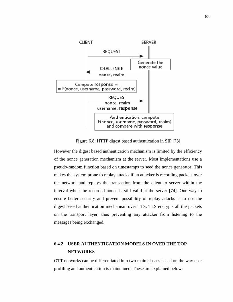
85
Figure 6.8: HTTP digest based authentication in SIP [73]
However the digest based authentication mechanism is limited by the efficiency
of the nonce generation mechanism at the server. Most implementations use a
pseudo-random function based on timestamps to seed the nonce generator. This
makes the system prone to replay attacks if an attacker is recording packets over
the network and replays the transaction from the client to server within the
interval when the recorded nonce is still valid at the server [74]. One way to
ensure better security and prevent possibility of replay attacks is to use the
digest based authentication mechanism over TLS. TLS encrypts all the packets
on the transport layer, thus preventing any attacker from listening to the
messages being exchanged.
6.4.2 USER AUTHENTICATION MODELS IN OVER THE TOP
NETWORKS
OTT networks can be differentiated into two main classes based on the way user
profiling and authentication is maintained. These are explained below:

86
Traditional P2P networks
The traditional peer to peer model means that there is no central server or
centralized authority in the network. All user information and identities are kept
in the overlay, inside the DHT. Any user can choose his own identity and can
add this into the DHT, without the need for any party to verify if the identity
really belongs to the user registering it.
This technique works well in P2P file sharing services or media streaming
applications, where multiple copies of the same information can be stored by
multiple peers. Each peer then in a way contributes to the huge database of files
which can be text, audio, video or other programs. Probably the most popular
example for such P2P networks ate those based on Bit Torrent [80]. In such
cases the DHTs are constructed based on the names/hashes of the files hosted by
different peers. When a user queries for a certain file or media stream, the DHT
is queried to locate all the possible peers that have a copy of the desired
file/stream. In such use cases, the user or client identities are not deemed to be
important, as long as they are hosting/contributing the necessary file or piece of
information. The DHT is searched against the name of the file, rather than the
identity of a specific user hosting it. In order to verify the integrity of the files,
their hash is cross checked with a known hash.
P2P based VoIP telephony services can also be built in such a fashion, although
it would find less promise to use such services over large networks. The reason
being that in telephony services, the user sitting behind the client is the key
being queried, and while the integrity of a file can be verified by computing a
hash on it, the integrity of a user can not be verified unless there is a trusted
authentication mechanism which verifies the user logged into his client.
[81] claims that in the absence of any central authority for identity assertion in a
distributed system, malicious nodes can create virtual or fake identities. Thus
authentication of participating nodes in truly distributed systems is a problem in
general. In P2P based telephony systems, authentication of user identities

87
(URIs) in the absence of any trusted central authority is an even more difficult
challenge to tackle [82].
Hybrid P2P networks
[83] uses the term “hybrid P2P networks” for networks which have centralized
indexing such as Napster [84]. In such networks, all the search queries are
directed towards the central indexing server while the data or services reside in
the P2P cloud. It is due to this mix of centralized and distributed architectures
that such networks are referred as being hybrid.
Having a closer look at some of the more widely used conversational P2P
services today, we find that they also exhibit hybrid properties. These services
are based on P2P concepts where all the call signaling and media streams flow
in a peer to peer fashion, but the user authentication and authorization is done in
a centralized manner. This is so because in conversational services a lot of
emphasis is placed on identifying a user correctly, and if the user profiles are
maintained within the DHT, there is a high risk of the information being corrupt
or completely wrong. Some of the most widely used conversational OTT
services are discussed below briefly for reference.
1. Skype:
Skype is one of the most widely used voice and video client over the internet. It
provides the facilities of instant messaging, file sharing, group voice chat, video
chat and lately group video chat as well. Although the protocol and operation of
Skype is confidential and is not released for the general public, studies on Skype
[46] reveal that the Skype registration and authentication process takes place
through central servers called as the Skype “login servers”. These servers keep
the login information of all skype users. The client keeps the login servers’
addresses inside the windows registry (when run on the MS Windows platform).
When a user wishes to start using the Skype services, she first has to
authenticate herself and only then is she allowed to connect to the Skype P2P

88
network. The rest of all mechanisms take place in a P2P fashion, where the
network is made up of normal end clients called nodes, and some faster and
more reliable peers which are nominated as super nodes. The super nodes
maintain a more robust backbone of the P2P network and the rest of the nodes
attach to these super-nodes.
2. Google Talk:
Google has also launched its chat client called Google Talk, which supports
instant messaging, file sharing, voice chat, and video chat capabilities. To use
GoogleTalk, one must have a registered account with Google. The use of the
GoogleTalk services begin by logging in to the Google account. This happens
by contacting the centrally located Google servers. Once authenticated, the call
signaling and media flow can take place in a peer to peer fashion using the
Libjingle library [68]. The same peer to peer method is employed when
transferring large files.
While within local networks, GoogleTalk operation remains strictly peer to peer
after the initial authentication is complete, but in larger networks, with firewall
and accessibility issues or where reliable peers can not be found, GoogleTalk
can quickly shift from P2P to a more server oriented architecture. Owing to the
large number of servers maintained and owned by google in the Internet, it has
the capability of readily providing relay-server capabilities to its users if they
cannot directly access each other due to the presence of firewalls and/or NATs.
In such cases all signaling and media streams flow through the relay server [69].
This differs from other conventional peer to peer systems and also Skype, where
the relay services are also provided by other peers (by super nodes in Skype
network [46]).
3. Apple FaceTime:

89
FaceTime [86] is another peer to peer voice and video chat service built by
Apple for Apple devices. It also works on the same principle as we discussed
above. The authentication is performed in centrally located FaceTime servers,
which are maintained by Apple itself. A user who wishes to use FaceTime either
has to register his phone number or his email address with the FaceTime service.
This establishes a binding between the device’s IP address and the user’s
email/phone number. Once the registration and authentication is complete, the
session signaling and media flow directly between the end devices in a peer to
peer fashion [67].
6.4.3 CHARGING MODELS FOR COOPERATING OTT AND
OPERATOR NETWORKS
To be able to charge a user, the operator networks must be able to authenticate
OTT users against a valid identity. For both types of authentication models in
OTT networks explained above, we need to come up with two corresponding
methods to authenticate OTT users in operator networks. Once the operator has
a valid identity of the user, he/she can be billed against a suitable and agreed
charging metric. In case of a video conference server such as MCU or a
transcoding service, the charging metric can be 1) utilized processing cycles, 2)
used time period, 3) utilized network bandwidth or a combination of all of these
metrics.
Charging users from OTT networks with centrally maintained registration
Because of the centrally administered user accounts and registrations,
charging/billing users of hybrid P2P networks is easier as compared to
traditional P2P networks discussed in section 6.4.2. The OTT service provider
can make billing agreements with the telco operator much like the roaming
agreements between different mobile operators. Standard AAA interfaces could
be opened on the login servers in the OTT domain, which would allow the telco

90
operator to access user authorization and account data from the OTT domain.
Simply put, when a user of the OTT service will request to use a service such as
an MCU from the telco operator network, the MCU will respond by asking for
authentication credentials from the user. For example in SIP this can be
accomplished by sending the 407 “proxy authorization required” response code.
In reply, the user’s client application will use the username and password
combination that had been used by the user to login initially to the OTT domain.
Once these credentials are sent to the operator’s MCU, it will authenticate these
from the OTT logon server using the standard AAA protocols such as Diameter
which should be implemented at both ends i.e. the operator’s billing/accounting
server and the OTT login server. If the logon server responds with a successful
response, a temporary identity will be created in the local operators
authentication servers, and the user will be allowed to use the desired service.
The operator may in turn send billing information to the OTT provider about the
service being used and how much should the user be charged.
The OTT service provider in turn can decide whether to charge the users
directly from their credit or by generating revenue through advertisements
played during the call.
We see that this model, while being a bit more complex in terms of contractual
arrangements, connects an OTT user seamlessly to the operator network by re-
using the same credentials as used to login to his OTT network through the
client application.
Charging of conventional P2P users
Although we see in the section 6.4.2 that conventional P2P networks are
generally not preferred for conversational services but for such type of P2P
networks which do not have any central authority or service provider based
model, the contract with an operator is not straight forward. Instead, the telecom
network operator will have to come up with simpler models to charge the users
directly. One such model is proposed below.

91
The operator hosting the MCU service will open an HTTP-based web interface
for external users, who can pay online using credit cards and reserve capacity in
the MCU for hosting video conferences. Once the reservation is made, the user
is issued a username and key pair. The same can also be done by selling
vouchers to users in open market, much like credit recharge vouchers sold for
mobile pre-paid customers. Once the user tries to establish a connection with the
MCU, it would respond with an “authentication required” message. In reply, the
user would provide the username and key obtained earlier through the operators
web shop or through the voucher purchase. This can be done for example
through a GUI that pops up on the users client device. The MCU would verify
the credentials with the database in the local network, and once verified, allow
the user to use the services for the specified capacity. The proposal is
demonstrated in Figure 6.10.
Figure 6.10: Charging model for inter operation between conventional P2P
networks and operator networks

92
6.5 SUMMARY
Cooperation between telecom operators and OTT service providers can bring
mutual benefits to both sides. While telecom operators have the promise to get
their user base back and still maintain profitability while offering new services,
OTT providers have the chance to offer more reliable services hosted inside the
network where otherwise users typically only rely on other peers to get services.
But such cooperation is not easy to establish and has certain pre-requisites both
in technical and business domains.
In terms of technical requirements, the OTT overlay network will need to have
some method in place to allow communication with external networks. One way
to accomplish this is to have some peers acting as proxy-peers. These peers will
serve as interfaces between the OTT network and external (operator based)
networks. In addition certain service discovery protocols need to be in place to
locate services in external networks. The operator network on the other hand
will have to modify its security and access policies to allow external users to
access services hosted inside the network. In cases where the inter-working
networks use different signaling protocols, some signaling gateway needs to be
in place to translate the protocols from one domain to another.
Meeting these technical requirements serves as the bare minimum to allow two
different domains to inter-work. They also need to have some mutual billing
logic in place so a domain can charge the users of another domain for using its
services. We see that many OTT providers offering voice and video
communication services today such as Skype, Google Talk and FaceTime have
centrally managed user registration and authentication information. If standard
AAA interfaces are opened on these central registrar/login servers, these same
credentials can be used by an operator network to identify and charge the OTT
users for service usage, provided the telco and OTT service provider have an
agreement beforehand. On the other hand, more trivial methods can be used to
charge users from P2P networks which do not have any centrally managed login
information. Distributing one time pass-codes in the form of vouchers can be

93
one possible way to allow users from such tradition P2P networks to use
services from the operator networks.
But such inter domain communication of course opens up new security
challenges for both the network and the users. We address these security
challenges in the next section.

94
7 SECURITY CONSIDERATIONS
Multimedia conferences in general impose a number of security requirements on
the system. Such requirements can be arranged into the domains of
authenticating a user before he or she can join the conference, authorize
participants of a conference to use certain features of the conference, privacy of
the users registered inside the conference as well as maintaining the
confidentiality of private information as it flows through the network.
7.1 TRUSTED NETWORK
The need to establish trust about the network becomes even more of a concern
when multiple domains or network players are involved. An example of this is
our proposed scheme, where media processing can be pushed to a third party
network while the conference members themselves belong to a different
network domain. The participants of the conference do not necessarily have a
direct association or registration with this third party network.
Earlier we discussed how the network can authenticate and authorize a user
accessing its services. However, the discussed solutions only cater for one way
authentication; only the network authenticates the user. This is also referred to
as client authentication. There should be ideally a two way authentication,
where the user is also capable of making sure that the network is legitimate and
trustworthy (referred to as network authentication or server authentication). This
is called bi-directional trust or mutual authentication [85]. This can be done for
example by using the well known public key of the operator network. The
network is asked to present its signature or certificate, which can then be
verified with the certificate authority. Once this verification is complete, the
user can be sure that he or she is connecting to the legitimate network and not a
spoofed network.

95
Figure 7.1: Establishing bi-directional trust
7.2 CONFIDENTIALITY
Maintaining true confidentiality, where no one except the source and the
intended destination of the information can read the information, is a challenge
when media processing is required from a third party. Confidentiality generally
means data encryption to make sure the information being exchanged does not
fall into the hands of any adversary listening on the way between the source and
destination nodes. This is normally accomplished by encrypting the data being
sent at the source, and only the destination node knows the key to decrypt it.
This makes it immune to any modification or sniffing by a man in the middle.
RTP, which is the most commonly used protocol for realtime media transport,
can secure the data using its variant called SRTP [87] which uses encryption to
Request to initiate session
Authentication required +
own digital signature Verifies digital
signature using
public key
Client sends own authentication data
Authentication complete
OK
client server
Network
authentication
User
authentication
External
network
Operator
domain

96
preserve confidentiality of the media streams. ZRTP [88] is another variation of
this protocol to accomplish the same objective.
When it comes to a network element such as a mixer or a transcoder, it
inevitably needs to decode the incoming streams in order to modify them and
then re-encodes them. This process of decoding, modifying and encoding
requires the MCU to be able to read the streams in unencrypted form. Thus, we
see that end to end confidentiality may be breached incase a third party node is
used for media processing.
Consider that a conference session in on going. We call the users attending the
conference as conference participants. Apart from the conference participants,
many other nodes may also be present in the network. In such a scenario, the
media mixing responsibilities can be handled in three different schemes:
7.2.1 MEDIA PROCESSING BY CONFERENCE PARTICIPANTS
In conventional peer to peer networks, enough information about another peer is
generally not available to establish complete trust. It is therefore not possible
without risking the loss of confidentiality, to delegate the responsibility of media
processing to any random peer which is ready to allocate its resources for the
task. To avoid this problem, most peer to peer networks restrict delegation of
media processing tasks to formal participants of a conference or session. In this
way, the media streams do not fall into a hands of any third party but remain
within the confines of the conference participants.
This has also been one of the hurdles impeding the usage of coordinated
transcoding/mixing in peer to peer networks. The choice of peer for media
processing tasks is only thus limited to the members of the current conference.
This scheme maintains the best confidentiality guarantees as the media streams
do not need to be propagated to any node other than the direct conference
participants.

97
7.2.2 MEDIA PROCESSING BY NETWORK HOSTED SERVERS
As long as there are capable peers within the conference who can effectively
handle media processing tasks, confidentiality and privacy of information is
maintained. But what happens when a capable peer is not present inside the
conference session.
A second way to handle media mixing tasks in within the conference is to
delegate the mixing responsibilities to the network, or specifically to servers
administered by trusted network operators. Media processing in the network
should not largely act as an obstacle since well known network operators can
not risk damaging their reputation in the market by illegally intercepting the
media streams and using them for purposes other than the intended media
transformations. Most network operators have strict confidentiality policies that
govern the use of their subscribers’ information. In case of any breach of
conduct, the network operator could be held responsible legally. Taking these
guarantees into account and assuming that bi-directional trust as discussed in
section 7.1 is enforced prior to media flow, it may be safe to some extent to use
the network for media processing.
7.2.3 MEDIA PROCESSING BY PEERS OUTSIDE THE
CONFERENCE
The more common way for an OTT network to handle media processing
demands in the absence of capable peers within the conference is to look for any
other capable peer in the overlay which may not be a part of the conference
session but is available to lend its resources for media mixing/transcoding. In
such a case the privacy or confidentiality is violated as all (unencrypted) media
streams will now flow through a peer which was otherwise not present in the
conference.

98
This renders such schemes as the worst in terms of providing confidentiality
guarantees due to the fact that any random peer in the overlay network can not
be trusted.
One may argue that some level of confidentiality can be achieved if media
processing tasks are broken down and distributed to different peers such that no
peer has access to the complete information. For example in a video conference,
a very trivial way to divide the media processing tasks among multiple nodes
would be to make sure that audio streams are mixed by one peer, say peer A,
while the video streams are being mixed by another peer, say peer B. B does not
have access to the audio streams and likewise A does not have access to the
corresponding video streams. More complex algorithms for dividing media
processing tasks can be developed. However one can not rule out the possibility
of a collusion attack [89]. In our example scenario, if A colludes with B and
allows B to access the audio streams, then B gets access to complete media
flow. Worse still, one adversary node can masquerade as multiple identities,
thus fooling other nodes to believe that they are distributing their media streams
to different nodes, while in practice, it’s the same node.
Thus in terms of maintaining confidentiality and privacy of information, we rate
the media processing schemes in the following order of decreasing preference:
1. By conference participants themselves
2. By servers hosted in a trusted network
3. By random peers in the overlay network willing to lend their resources
for media processing.
7.3 USER PRIVACY
Privacy means that a user can hide its name or contact information while
participating in a conference. In this case, other conference members will see
this user as anonymous. This can be useful in cases where a user would not want

99
to actively participate in a conference or discussion but just to listen to the other
participants (such as an online training session or classroom).
User privacy guarantees are as such provided by the signaling protocol in use.
SIP provides mechanism for maintaining user privacy as given in [90][91]. This
makes privacy a subject of merely choosing the correct signaling protocol rather
than asserting any strict dimensioning limitations on the conference architecture.

100
8 CONCLUSIONS
OTT service providers and network operators have been competing with each
other now for a decade to establish their ownership over the services that the end
users receive. While the tussle continues, network operators see an ever
increasing “revenue-less” traffic on their networks. This traffic utilizing
operator’s network bandwidth and capacity does not bring with it an equally
growing revenue due to the fact that the services are provided by third party
over the top organizations, while the operator network only gets paid for transfer
of bits of data from one end to the other. This by proportion is a very small
portion of the revenue that the network operators hope to generate with their
network resources.
At one end this forces operators to try out dire measures such as blocking off
OTT traffic from their networks At the other end, the prospects of decaying
traffic and demand for network hosted services is causing operators to cut down
on their investments to host high-end servers inside their networks.
Taking this as a background for the research, the first question we aimed to
answer was whether there is still a requirement for high-end and reliable servers
inside the network, or should the operators just succumb to the threat imposed
by the OTT business and let the client devices handle their own loads through
the use of OTT Peer to Peer networks. In the past OTT service providers have
used the operators' network infrastructure as a bit pipe without harnessing any
intelligence or support from the underlying network. While this has worked for
the OTT industry to some degree for voice based services over IP, however with
the increasing demand for video based applications such as video streaming and
video conferencing, the OTT applications can benefit from the support of the
underlying network considering that video poses more stringent requirements on
bandwidth, CPU and energy. We presented statistics suggesting that for good
quality average to large scale video conferences, support from the network is
required for video mixing and transcoding. Thus in contrast to IP telephony,
when it comes to video based services we see that even if the OTT industry has

101
come up with better and more reliable protocols, end devices especially hand
held devices today are not capable to handle such processor and in turn energy
requirements themselves. Support from the underlying network can be used to
the advantage in such situations. For applications with strict bandwidth
requirements, the underlying network can also provide QoS guarantees. We
argue that OTT applications can benefit more by using the underlying network
as a smart pipe or intelligent pipe rather than a dumb bit pipe.
With this as a motivation, this thesis looked into some scenarios where telco
operators and OTT service providers could mutually benefit from each other
through collaborative contracts. In this way, the business fear for operators
could be turned to a profit by bringing the OTT user base back to the operator
networks for using services such as video mixing and transcoding in case of
video conferencing. Some scenarios for such a collaboration were evaluated and
requirements to practically implement such cooperation were discussed. It is
seen that the technical components for bridging the gap between OTT and
operator based networks already exist. This is especially straight forward in
cases where the two domains use the same signaling protocols such as P2P-SIP
in OTT network and SIP in IMS networks. But even in scenarios with differing
protocols, certain signaling gateway functions can be deployed at the edge of the
networks to allow interworking. We see that the major hurdle obstructing the
cooperation between OTT and mobile operator networks is finding the right
business models.
Once the OTT service providers realize the benefit in smart pipes over dumb bit
pipes, they can tailor their applications to make use of the network hosted
intelligence to offer better and more reliable services. The network operators on
the other hand realizing the potential in OTT applications can transform their
core network offerings from the one-size-fits-all flat rate data plans to multi
tiered services customized for different types of users having different
requirements. Such a model also bridges the gap between traffic and revenue
growth. The operators can open up interfaces to their networks which can be
102
used by third party OTT applications. Such interfaces can range from requesting
network QoS, to invoking network hosted media processing services, video
recording services, NAT traversal services, voice/video mail services or even
accessing the user location data and subscriber profiling data for more tailored
service experience.
The business models associated with such partnering OTT and operator based
services will be most likely based on revenue sharing, however the exact
specifics of how the business ecosystem will evolve are hard to predict. A lot
depends on how various players in the industry react to such an evolving
ecosystem. How openly will operators allow third party OTT applications to
leverage their network hosted intelligence and what terms will govern such
revenue sharing agreements? And last but not the least, various telecom
operators also tend to compete with each other. Such competition between
operators will also play a vital role in determining which operators partner with
which OTT service providers.
8.1 FUTURE RESEARCH:
As with every research work, there is room for improvement in this thesis.
Many topics within the scope of the broader research area still remain open for
further discussion and research.
Specific to video conference, there remains a need to explore in detail the
impact of having large scale conference sessions that involve peers from
multiple cooperating networks. Video conferences can range from small scale
sessions involving cooperation between one operator network and one OTT
network to large scale more complex sessions involving many nodes belonging
to different networks where some networks might be cooperating while others
may be competing at the same time. Depending on the exact dynamics of a
conference session, a purely centralized or purely distributed architecture may
not scale well or may not be possible at all. Since such scenarios are often hard
103
to analyze due to the unavailability of large scale test networks, network
simulations can be performed to see how the network behaves when subjected to
varying traffic and when nodes are arranged in different topologies. Network
traffic patterns may be analyzed to calculate the most suitable architecture.
Operators also need to clearly identify which interfaces are they willing to open
for external users, and how will this impact the overall security and performance
of their network assets. In the presence of both external and internal users, a
network may have to give higher preference to one class of users, especially
when the network is low on resources.
Business collaboration between different players is also an intensely debated
topic which was partially covered by this thesis. Even though we believe and
motivate that there are good business prospects in cooperation between telecom
operators and OTT service providers yet, moving from competition towards
cooperative contracts will effect the business ecosystem in the communications
industry in general. It is yet to be researched how the market will react to
diminishing competition in favor of such cooperation. Although it is quite clear
that such cooperation will be based on contracts involving revenue sharing
models but the exact pricing and billing strategies for OTT users who use
network hosted services and vice versa need to be planned in more detail.
User behavior is also another aspect that will play a vital role in determining
whether such cooperation is successful in accomplishing what it promises. For
example, whether the general community will react positively to more reliable
but comparatively costly services or whether users will generally prefer a less
reliable service simply because it is less costly or free. It should also be kept in
mind that the user of a service may not be an individual in all cases but may also
be one or many enterprises and organizations. More appropriate applications
that target a specific user base can be used to statistically analyze user behavior
patterns. Cooperative models may need to be tailored according to user
expectations.
104
As part of any future research work, other avenues may also be sought where
the underlay and overlay networks can mutually share information and resources
to provide better services.

105
REFERENCES
[1] P. Moulton: The Telecommunications Survival Guide. Prentice Hall
PTR, 2000, ISBN: 0130281360. [2] High-Definition: The Evolution Of Video Conferencing. White Paper,
2005. http://www.polycom.com/global/documents/whitepapers/high_definition_the_evolution_of_video_conferencing.pdf
[3] I. Dalgic and H. Fang: Comparison of H. 323 and SIP for IP
Telephony Signaling. Proceesings of the SPIE conference on Multimedia Systems and Applications II, 1999. http://academic.research.microsoft.com/Publication/2367540
[4] W. Greene and B. Lancaster: Over the Top Services. White Paper,
Nov 2007. http://www.ltcinternational.com/inside-
out/uploads/ltc_otts_whitepaper.pdf
[5] AT&T Connect - Video Conferencing Functional and Architectural
Overview, White Paper, Sep 2009. http://uc.att.com/support/PDF/8.8.5x/White%20Papers/ATT_Connect_Video_Conferencing_WP_v.8.8_SP1_EE.pdf
[6] J. Erman, A. Gerber, K.K. Ramakrishnan, S. Sen, O. Spatscheck:
Over The Top Video: the Gorilla in Cellular Networks. In proceedings of Internet Measurement Conference, ACM SIGCOMM, Nov 2011.
[7] B.G. Mölleryd, J. Markendahl, J. Werding, Ö. Mäkitalo: Decoupling of
revenues and traffic - Is there a revenue gap for mobile broadband?. In Proceedings of 9th Conference of Telecommunication, Media and Internet Techno-Economics (CTTE´10), June 2010.
[8] Nokia Siemens Networks: Implementing fair service usage policies for
peer-to-peer traffic. White Paper. 2007. http://w3.nokiasiemensnetworks.com/NR/rdonlyres/9BDAD945-63F3-4D3A-A3CF-DC3AC029E7F7/0/Flexi_ISN_P2P_brochure.pdf
[9] B. Furht: Encyclopedia of Multimedia, 2nd Edition. Dec 2008. ISBN:
0387747249. Page 661. [10] P. Koskelainen, J. Ott, H. Schulzrinne and X. Wu: Requirements for
Floor Control Protocols. RFC 4376, Feburary 2006. http://www.ietf.org/rfc/rfc4376.txt
[11] G. Camarillo, J. Ott and K. Drage: The Binary Floor Control Protocol
(BFCP). RFC 4582, November 2006. http://www.ietf.org/rfc/rfc4582.txt
106
[12] P. Koskelainen, H. Schulzrinne and X. Wu: Use of Session Initiation
Protocol (SIP) and Simple Object Access Protocol (SOAP) for Conference Floor Control. Internet Draft, March 2003. http://tools.ietf.org/html/draft-wu-sipping-floor-control-04, Expired.
[13] Internet Engineering Task Force, Request for Comments.
http://www.ietf.org/rfc.html [14] International Telecommunications Union, Recommendations.
http://www.itu.int/en/ITU-T/publications/Pages/recs.aspx [15] S. Firestone, T. Ramalingam and S. Fry: Voice and Video
Conferencing Fundamentals. Cisco Press. March 2007. ISBN: 1-58705-268-7.
[16] An Overview of H.323 - SIP Interworking. Radvision. Technical
Paper, 2001. http://www.radvision.com/NR/rdonlyres/1B7C291A-148C-4506-8312-D6DA2C58C7B7/0/OverviewofH323SIPInterworking.pdf
[17] ITU-T: Packet Based Multimedia Communications Systems,
Recommendation H.323, International Telecommunication Union, December 2009.
[18] ITU-T: ISDN user-network interface layer 3 specification for basic call
control, Recommendation Q.931, International Telecommunication Union, May 1998.
[19] ITU-T, Call Signaling Protocols and Media Stream Packetization for
Packet Based Multimedia Communications Systems, Recommendation H.225.0, International Telecommunication Union, December 2009.
[20] C. Bormann, D. Kutscher, J. Ott and D. Trossen: Simple Conference
Control Protocol – Service Specification. Internet Draft, February 2001. http://tools.ietf.org/html/draft-ietf-mmusic-sccp-01, Expired.
[21] R. Fielding, J. Gettys, J. Mogul, H. Frystyk, L. Masinter, P. Leach and
T. Berners-Lee: Hypertext Transfer Protocol -- HTTP/1.1. RFC 2616. June 1999. http://www.ietf.org/rfc/rfc2616.txt
[22] M. Handley and V. Jacobson. SDP: Session Description Protocol.
RFC 2327. April 1998. http://www.ietf.org/rfc/rfc2327.txt [23] ITU-T: Control Protocol for Multimedia Communication,
Recommendation H.245, International Telecommunication Union. May 2011.

107
[24] H. Schulzrinne, S. Casner, R. Frederick and V. Jacobson: Realtime transport protocol (RTP). RFC 3550, July 2003. http://www.ietf.org/rfc/rfc3550.txt
[25] S. Torrance: The two sided telecoms market opportunity, Telco 2.0.
Strategy Report. March 2008. http://www.stlpartners.com/telco2_2-sided-market/index.php
[26] Ericsson partnering with Akamai. Cited Dec 2011.
http://www.akamai.com/ericsson [27] M. Alvarez, E. Salami, A. Ramirez and M. Valero: A performance
characterization of high definition digital video decoding using H.264/AVC. Proceedings of Workload Characterization Symposium. IEEE International. October 2005. Pages: 24 – 33
[28] YouTube. http://www.youtube.com [29] J. Ozer: YouTube does 720P HD using H.264. Cited August 2011.
http://www.streaminglearningcenter.com/articles/youtube-does-720p-hd-using-h264.html
[30] S. Wenger, M.M. Hannuksela, T. Stockhammer, M. Westerlund and
D. Singer. RTP Payload Format for H.264 Video. RFC 3984, February 2005. http://www.ietf.org/rfc/rfc3984.txt
[31] Real-world LTE performance for public safety. White Paper.
September 2010. http://www.tsag-its.org/docs/real-world-lte-performance.pdf
[32] S. A. Stople: A Benchmark Study on Broadband Utilization in the
Accommodation Sector of the Hardangerfjord Area in Norway. December 2010. http://www.sngroup.com/wp-content/uploads/2011/01/A-Benchmark-Study-on-Broadband-Utilization-in-the-accommodation-sector-in-the-hardanger-fjord-area-Norway_SA-Stople-Fall-2010.pdf
[33] R. Bindal, P. Cao, W. Chan, J. Medval, G. Suwala, T. Bates and A.
Zhang: Improving Traffic Locality in BitTorrent visa Biased Neighbor Selection. in proceedings of 26th IEEE International Conference on Distributed Computing Systems, 2006. ICDCS 2006. Page: 66.
[34] ADSL2 and ADSL2+ High-Speed WAN Interface Cards. Cisco public
information document. Cited August 2011. http://www.cisco.com/en/US/prod/collateral/routers/ps5853/qa_c67_521131.pdf
[35] G. Camarillo and A. Johnston: Conference Establishment Using
Request-Contained Lists in the Session Initiation Protocol (SIP). RFC 5366. October 2008. http://www.ietf.org/rfc/rfc5366.txt

108
[36] J. Lennox and H. Schulzrinne: A protocol for reliable decentralized
conferencing. In Proceedings of the 13th international Workshop on Network and Operating Systems Support for Digital Audio and Video (NOSSDAV). 2003.
[37] Skype. http://www.Skype.com [38] M. Handley, C. Perkins and E. Whelan: Session Announcement
Protocol. RFC 2974. October 2000. http://www.ietf.org/rfc/rfc2974.txt [39] J. Rosenberg, J. Peterson, H. Schulzrinne and G. Camarillo. Best
Current Practices for Third Party Call Control (3pcc) in the Session Initiation Protocol (SIP). RFC 3725. April 2004. http://www.ietf.org/rfc/rfc3725.txt
[40] J. Rosenberg: A Framework for Conferencing with the Session
Initiation Protocol (SIP). RFC 4353. February 2006. http://www.ietf.org/rfc/rfc4353.txt
[41] Dawen Song, Yijun Mo and Furong Wang: Architecture of multiparty
conferencing using SIP. In proceedings of Wireless Communications, Networking and Mobile Computing, IEEE. Pages: 1361 - 1364. December 2005.
[42] G. Camarillo: Peer-to-Peer (P2P) Architecture: Definition,
Taxonomies, Examples, and Applicability. RFC 5694. November 2009. http://www.ietf.org/rfc/rfc5694.txt
[43] Cost-effective Transcoding for Carriers, White Paper, September
2006. http://www.ditechnetworks.com/learningcenter/whitepapers/wp_codec_transcoding.pdf
[44] E. Marocco and D. Bryan: Interworking between P2PSIP Overlays
and Conventional SIP Networks, Internet Draft, March 2007.
http://tools.ietf.org/html/draft-marocco-p2psip-interwork-01, Expired.
[45] E. Marocco, A. Manzalini, M. Sampò and G. Canal: Interworking
between P2PSIP Overlays and IMS Networks – Scenarios and Technical Solutions. 2008.
http://www.p2psip.org/docs/p2psip_ims.pdf [46] S. A. Baset and H. Schulzrinne: An Analysis of the Skype Peer-to-
Peer Internet Telephony Protocol, In proceedings of INFOCOM 2006, IEEE International Conference on Computer Communications. Pages: 1 – 11. April 2006.
[47] PPLive. http://www.pplive.com.

109
[48] X. Hei, C. Liang, J. Liang, Y. Liu and K.W. Ross: A Measurement Study of a Large-Scale P2P IPTV System. IEEE Transactions on Multimedia. Pages: 1672 – 1687. Dec 2007.
[49] J. shi, Y. Ji, H. Zhang and Y. Li: A Hierarchical P2P-SIP Architecture,
Internet Draft, August 2006. http://tools.ietf.org/html/draft-shi-p2psip-
hier-arch-00, Expired.
[50] E. Guttman, C. Perkins and J. Veizades: Service Location Protocol
Version 2. RFC 2608, June 1999. http://tools.ietf.org/html/rfc2608
[51] G. Brown: Monetization opportunities for mobile operators. White Paper. Cited Dec 2011. http://www.cisco.com/en/US/solutions/collateral/ns341/ns973/Cisco-Mobile-Monetization-WP.pdf
[52] Spotify. http://www.spotify.com
[53] 3 UK. http://www.three.co.uk
[54] Akamai. http://www.akamai.com
[55] Ericsson. http://www.ericsson.com
[56] NTT Docomo's I-mode service.
http://www.nttdocomo.com/services/imode/business/index.html
[57] F. Chen, T. Repantis and V. Kalogeraki: Coordinated Media Streaming and Transcoding in Peer-to-Peer Systems, In proceedings of IPDPS 2005, IEEE International Parallel and Distributed Processing Symposium. April 2005.
[58] V. Samanta, R. Oliveira, A. Dixit, P. Aghera, P. Zerfos, S. Lu: Impact
of Video Encoding Parameters on Dynamic Video Transcoding. In proceedings of Comsware, first international conference on Communication System Software and Middleware. Pages: 1-9. 2006.
[59] W. Y. Lum, F. C.M. Lau: On balancing between transcoding
overhead and spatial consumption in content adaptation. In Proceesings of MobiCom, the 8th annual international conference on Mobile computing and networking. 2002.
[60] J. Noh, M. Makar, B. Girod: Streaming to mobile users in a peer-to-
peer network. In proceedings of Mobimedia, the 5th International ICST Mobile Multimedia Communications Conference, 2009.
[61] A. Warabino, S. Ota, D. Morikawa, M. Ohashi, H. Nakamura, H.
Iwashita, F. Watanabe: Video transcoding proxy for 3Gwireless mobile Internet access. Apears in Communications Magazine, IEEE. Oct 2000. Pages: 66-71.
110
[62] A. Johnston and R. Sparks: Session Description Protocol (SDP)
Offer/Answer Examples. RFC 4317. Dec 2005. http://tools.ietf.org/html/rfc4317.
[63] Performance Statistics for Video Encoding & Decoding. Texas
Instruments. Cited July 2011, http://processors.wiki.ti.com/index.php/DM365_Performance
[64] ITU-T: One-way transmission time, Recommendation G.114,
International Telecommunication Union. May 2003. [65] D. Meddour, M. Mushtaq and T. Ahmed: Open Issues in P2P
Multimedia Streaming. In proceedings of MULTICOMM 2006 held in conjunction with IEEE ICC 2006. pages 43 – 48. June 2006.
[66] O. Ulusoy: Research issues in Peer-to-Peer data management.
Published in IEEE 22nd International Symposium on Computer and information sciences. Pages: 1-8. Nov 2007.
[67] Apple FaceTime on Multimedia-Grade Aruba WLAN, White Paper.
January 2011. http://www.arubanetworks.com/pdf/technology/whitepapers/WP_Apple-FaceTime.pdf
[68] Mike Jazayeri: What is libjingle. Google Talkabout blog. cited August
2011. http://googletalk.blogspot.com/2005/12/what-is-libjingle.html [69] R. Alshammari and A. N. Zincir-Heywood: Insight into the Gtalk
Protocol. Technical Report. Feburary 2010. [70] D. R. Choffnes and F. E. Bustamante: Taming the torrent: a practical
approach to reducing cross-isp traffic in peer-to-peer systems. Proceedings of ACM SIGCOMM 2008 conference on Data communication. October 2008.
[71] V. Aggarwal, A. Feldmann and C. Scheideler: Can ISPS and P2P
users cooperate for improved performance? Appears in ACM SIGCOMM Computer Communication Review, Volume 37 Issue 3. July 2007.
[72] D. Thanh, I. Jorstad, P. Engelstad, T. Jonvik, B. Feng and D. Thuan:
Authentication in a Multi-access IMS Environment. In proceedings of WIMOB '08, IEEE International Conference on Wireless and Mobile Computing. Pages 613 - 618. October 2008.
[73] S. Stefano, V. Luca and P. Donald: SIP security issues: the SIP
authentication procedure and its processing load. Appears in IEEE Network, Volume 16, Issue 6. Pages 38 - 44. December 2002.

111
[74] J. Franks, P. Hallam-Baker, J. Hostetler, S. Lawrence, P. Leach, A. Luotonen and L. Stewart: HTTP Authentication: Basic and Digest Access Authentication. RFC 2617. June 1999. http://tools.ietf.org/html/rfc2617
[75] Rosenberg J., Schulzrinne H., Camarillo G., Johnston A., Peterson J.,
Sparks R., Handley M. and Schooler E: SIP: Session Initiation Protocol. RFC 3261. June 2002. http://www.ietf.org/rfc/rfc3261.txt
[76] Dialogic: Mobile Video - A New Opportunity. White Paper. Cited Dec
2011. http://www5.dialogic.com/products/docs/whitepapers/11296-mobile-video-wp.pdf
[77] G. Camarillo: Framework for Transcoding with the Session Initiation
Protocol (SIP). RFC 5369. October 2008. http://www.ietf.org/rfc/rfc5369.txt
[78] G. Camarillo: The Session Initiation Protocol (SIP) Conference Bridge
Transcoding Model. RFC 5370. October 2008. http://www.ietf.org/rfc/rfc5370.txt
[79] G. Camarillo, E. Burger, H. Schulzrinne and A. van Wijk: Transcoding
Services Invocation in the Session Initiation Protocol (SIP) Using Third Party Call Control (3pcc). RFC: 4117. June 2005. http://www.ietf.org/rfc/rfc4117.txt
[80] B. Cohen. The BitTorrent Protocol Specification. Cited August 2011.
http://www.bittorrent.org/beps/bep_0003.html
[81] J. R. Douceur: The sybil attack. Revised Papers from the First International Workshop on Peer-to-Peer Systems, Cambridge, MA (USA), March 2002, LNCS, Vol. 2429, Springer.
[82] J. Seedorf: Security Issues for P2P-Based Voice and Video-
Streaming Applications. Published in In iNetSec 2009. Pages 95-110.
[83] J. Risson, T. Moors: Survey of research towards robust peer-to-peer networks: search methods. Published in International Journal of Computer and Telecommunications Networking. December 2006.
[84] Napster. http://www.napster.com [85] V. Niemi and K. Nyberg: UMTS security. John Wiley and Sons, 2003.
ISBN: 978-0-470-84794-7 [86] Apple FaceTime. www.apple.com/mac/facetime/ [87] M. Baugher, D. McGrew, M. Naslund, E. Carrara and K. Norrman:
The Secure Realtime Transport Protocol (SRTP). RFC 3711. March 2004. http://www.ietf.org/rfc/rfc3711.txt
112
[88] P. Zimmermann, A. Johnston Ed, and J. Callas: ZRTP: Media Path
Key Agreement for Unicast Secure RTP. RFC 6189. April 2011. http://www.ietf.org/rfc/rfc6189.txt
[89] Y. Wu, F. Bao: Collusion attack on a multi-key secure video proxy
scheme. In proceedings of MULTIMEDIA, the 12th annual ACM international conference on Multimedia, 2004.
[90] M. Munakata, S. Schubert and T. Ohba: User-Agent-Driven Privacy
Mechanism for SIP. RFC 5767. April 2010. http://www.ietf.org/rfc/rfc5767.txt
[91] J. Peterson: A Privacy Mechanism for the Session Initiation Protocol
(SIP). RFC 3323. November 2002. http://www.ietf.org/rfc/rfc3323.txt [92] Fast Guide to DSL (Digital Subscriber Line), TechTarget. Cited
August 2011. http://whatis.techtarget.com/definition/0,,sid9_gci213915,00.html#dslsumry
[93] GSM Handset information, GSM Arena. Cited January 2011.
http://www.gsmarena.com

113
APPENDIX 1
SMART PHONES PROCESSING AND DISPLAY CAPABILITIES
Phone Display resolution CPU
Samsung i997 Infuse 4G 480x800 1.2GHz
Apple iPad 768 x 1024 1 GHz
HTC Desire S 480x800 1GHz
Motorola PRO 320x480 1GHz
HTC HD7 480x800 1GHz
Sony Ericsson BRAVIA S004 480x854 1GHz
Acer Stream 480x800 1GHz
Apple iPhone 4 16GB 640x960 1GHz
Samsung I9100 Galaxy S II 480x800 1GHz Dual-core
Nokia E71 320 x 240 369 MHz
Nokia X6 360 x 640 434 MHz
Motorola XT301 240 x 320 528 MHz
HTC Pure 480 x 800 528 MHz
Sony Ericsson XPERIA X8 320 x 480 600 MHz
Nokia N8 360 x 640 680 MHz
Nokia C7 360 x 640 680 MHz
Sony Ericsson Vivaz pro 360 x 640 720 MHz
Acer Liquid E 480x800 768MHz
Samsung Galaxy Ace S5830 320x480 800MHz
Nokia N95 240x320 Dual 332 MHz
Smart phones features [93]
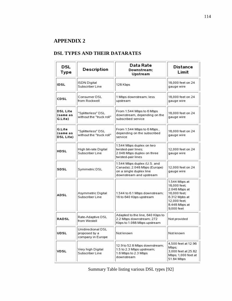
114
APPENDIX 2
DSL TYPES AND THEIR DATARATES
Summary Table listing various DSL types [92]