
Media Access Control #7 - KU ITTCfrost/EECS_563/LOCAL/EECS_563_Class_Notes-Fall... · MAC 5 Media...
59
1 MAC Media Access Control #7 2 MAC Outline Why use MAC protocols General classes of MAC protocols Deterministic Random Access Standard LAN protocols Broadband Access Cable DSL Other.. Satellite Networks
Transcript of Media Access Control #7 - KU ITTCfrost/EECS_563/LOCAL/EECS_563_Class_Notes-Fall... · MAC 5 Media...
1MAC
Media Access Control#7
2MAC
Outline
� Why use MAC protocols� General classes of MAC protocols
� Deterministic� Random Access
� Standard LAN protocols� Broadband Access
� Cable� DSL� Other..
� Satellite Networks

3MAC
Media Access Control: Protocols provide:
� Direct access to the media
� Distributed control over resource allocation
� Typically broadcast (real or virtual)
4MAC
Media Access Control: Advantages� High data rates
(open new applications)
� Low cost
� Local organizational control
� Wireless is a broadcast media and efficient use of resources is important
� Enable sharing of resources
�Mobility via Wireless

5MAC
Media Access Control� MAC protocols establish a set of rules that govern who gets to use the shared transmission media in an efficient manner.
� Obstacle to perfect channel utilization
� Finite propagation delay means that each users’ knowledge of the state of the system is imperfect and thus they can not perfectly schedule transmissions, i.e., some time will be wasted attempting to learn the state of the system and/or learning the fate of transmissions.
� Lost messages
6MAC
Media Access Control
� Perfect Knowledge would lead to FIFO performance.
� Performance of MAC protocols will be compared to FIFO performance.
Ideal MACPerformance

7MAC
Impact of MAC OverheadT
ransf
er D
elay
Load
E[T]/E[X]
ρSmax-2 1
1
Smax-1
MAC Protocol 1
MAC Protocol 2
Adapted from: Leon-Garcia & Widjaja: Communication Networks
8MAC
Alternative Media Access Control Strategies� Static Allocation
� FDM
� TDM
� Problems
� Management; not easy to add users– Requires signaling
� Wasteful in resources for bursty traffic� Example
� A transmission media has a rate of 10 Mb/s and supports 50 users. The system uses static allocation. A user has a 1 Mbyte file to transmit. The file transfer time is:

9MAC
Alternative Media Access Control Strategies
� Suppose you send a message to all the other 49 users saying, ‘I need the whole channel for about 1sec, do not use it, please’
�As long as the overhead incurred in sending the message is less than 39 sec. the user will get better performance.
10MAC
Alternative Media Access Control Strategies
� Deterministic
� Polling
� Token networks
� Random Access
�ALOHA
�Carrier sense multiple access (CSMA)
�CSMA with collision detection (CSMA/CD)

11MAC
Alternative Media Access Control Strategies: Dynamic allocation of resources
� Deterministic; Polling, Token Ring &Token Bus
� Advantage: the maximum time between users chances to transmit is bounded. (assuming a limit on the token holding time)
� Disadvantage: Time is wasted polling other users if they have no data to send.
� The technology does not scale
12MAC
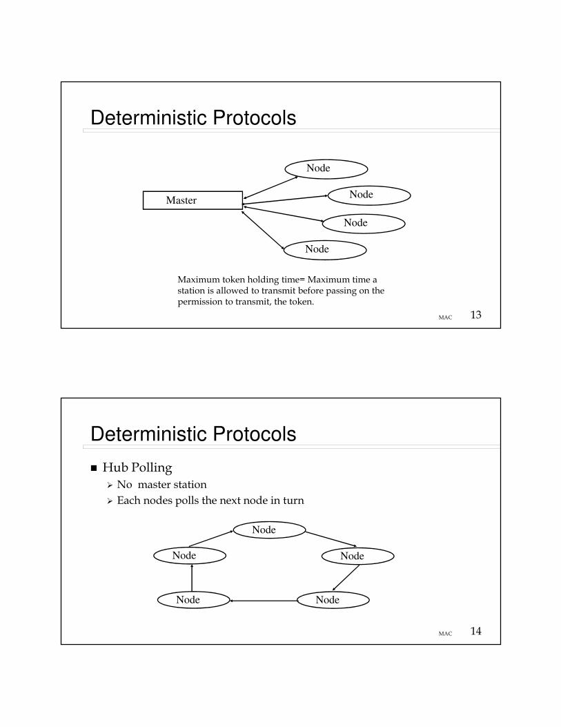
Deterministic Protocols
�Roll Call Polling�Master/slave arrangement
�Master polls each node; Do you have data to send?
�If the polled node has data it is sent otherwise next node is polled.
13MAC
Deterministic Protocols
Master
Node
Node
Node
Node
Maximum token holding time= Maximum time a station is allowed to transmit before passing on the permission to transmit, the token.
14MAC
Deterministic Protocols
� Hub Polling
� No master station
� Each nodes polls the next node in turn
Node
Node
NodeNode
Node
15MAC
Deterministic Protocols
� Example:� # nodes = 10� Link rate = 1 Mb/s� Packet Size = 1000 bits� Assume Low load � no queueing� Assume node interface delay = 0� 0.1 ms between nodes (30 km/(3x108m/s) = 0.1ms)� Find the effective transmission rate and efficiency.
– On average destination is 5 nodes away � .5 ms– Time to transmit 1000 bits = 0.5 ms + 1 ms = 1.5 ms– Effective transmission rate = 1000 bits/ 1.5 ms = 666Kb/s– Efficiency = (666 Kb/s)/(1000 Kb/s) = 0.66
� Repeat for link rate = 10 Mb/s– On average destination is 5 nodes away � .5 ms– Time to transmit 1000 bits = 0.5 ms + .1 ms = .6 ms– Effective transmission rate = 1000 bits/ .6 ms = 1.67 Mb/s– Efficiency = (1.67 Mb/s)/(10 Mb/s) = 16.7%
� Conclusion� Polling does not scale with link rate
16MAC
17MAC
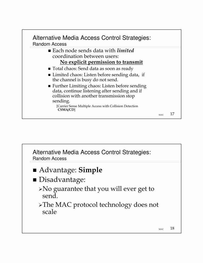
Alternative Media Access Control Strategies: Random Access
� Each node sends data with limitedcoordination between users:
No explicit permission to transmit� Total chaos: Send data as soon as ready
� Limited chaos: Listen before sending data, if the channel is busy do not send.
� Further Limiting chaos: Listen before sending data, continue listening after sending and if collision with another transmission stop sending.[Carrier Sense Multiple Access with Collision Detection CSMA/CD]
18MAC
Alternative Media Access Control Strategies: Random Access
� Advantage: Simple
� Disadvantage: �No guarantee that you will ever get to send.
�The MAC protocol technology does not scale
19MAC
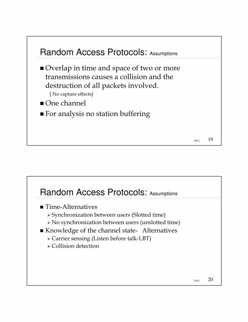
Random Access Protocols: Assumptions
�Overlap in time and space of two or more transmissions causes a collision and the destruction of all packets involved.[ No capture effects]
�One channel
� For analysis no station buffering
20MAC
Random Access Protocols: Assumptions
� Time-Alternatives� Synchronization between users (Slotted time)
�No synchronization between users (unslotted time)
� Knowledge of the channel state- Alternatives�Carrier sensing (Listen before talk-LBT)
�Collision detection
21MAC
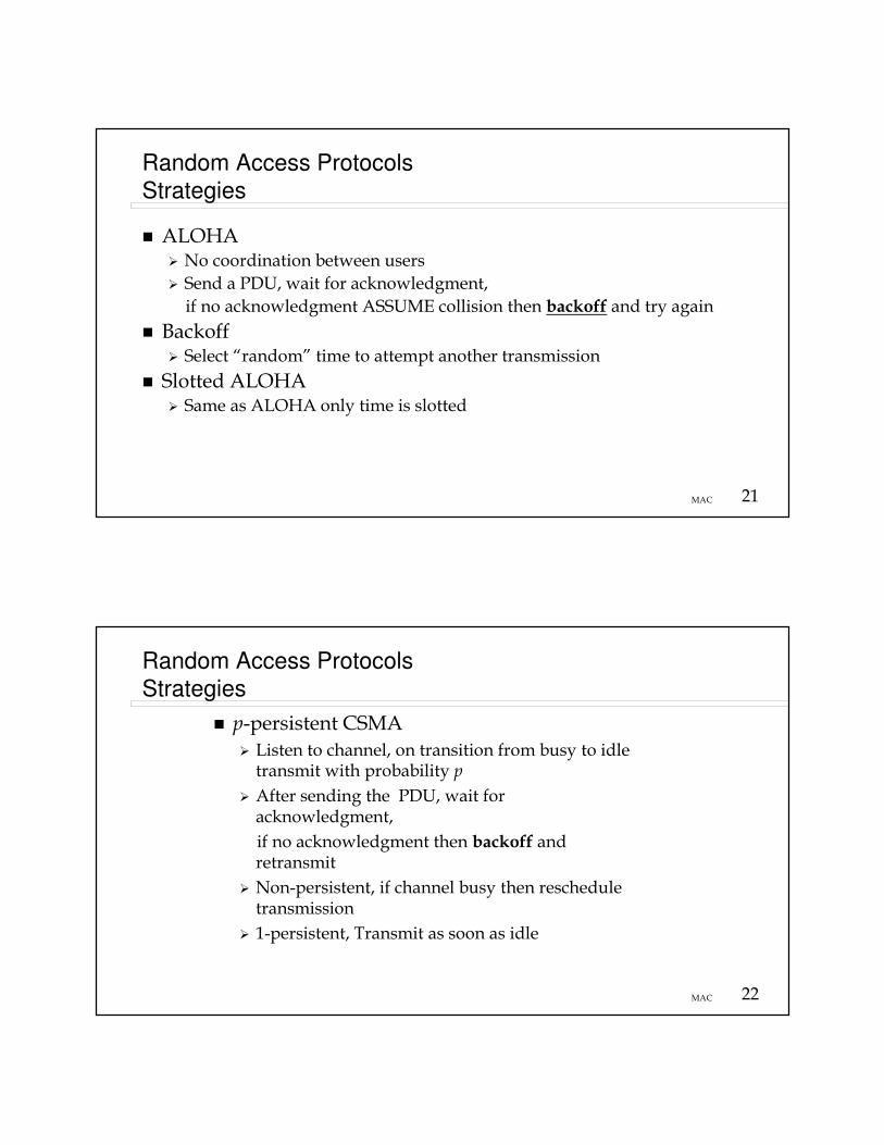
Random Access Protocols
Strategies
� ALOHA� No coordination between users
� Send a PDU, wait for acknowledgment,
if no acknowledgment ASSUME collision then backoff and try again
� Backoff� Select “random” time to attempt another transmission
� Slotted ALOHA� Same as ALOHA only time is slotted
22MAC
Random Access Protocols
Strategies
� p-persistent CSMA
� Listen to channel, on transition from busy to idle transmit with probability p
� After sending the PDU, wait for acknowledgment,
if no acknowledgment then backoff and retransmit
� Non-persistent, if channel busy then reschedule transmission
� 1-persistent, Transmit as soon as idle
23MAC
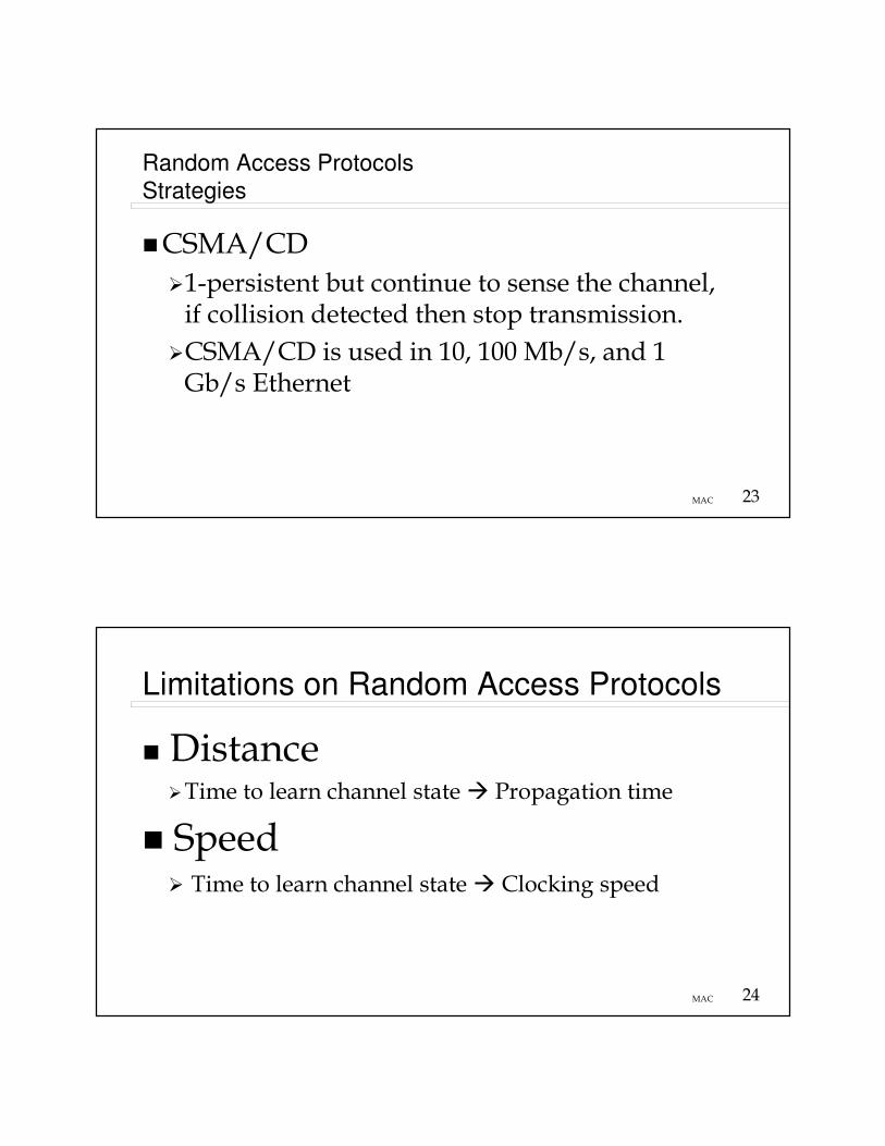
Random Access Protocols
Strategies
�CSMA/CD
�1-persistent but continue to sense the channel, if collision detected then stop transmission.
�CSMA/CD is used in 10, 100 Mb/s, and 1 Gb/s Ethernet
24MAC
Limitations on Random Access Protocols
� Distance�Time to learn channel state � Propagation time
� Speed� Time to learn channel state � Clocking speed

25MAC
Random Access ProtocolsAnalysis of ALOHA:
� Goal: Find Smax� Protocol Operation
� Packet of length L (sec) arrives at station i– Station i transmits immediately
– Station i starts an acknowledgment timer
� If no other station transmits while i is transmitting then success
� Else a collision occurred
� Station i learns that a collision occurred if the acknowledgment timer fires before the acknowledgment arrives
26MAC
Random Access ProtocolsAnalysis of Aloha
� If collision detected then station i retransmitts at a later time, this time is pseudo-random and is determined by a backoff algorithm
�Design Issue:
�Determine the maximum normalized throughput for an Aloha system

27MAC
Random Access ProtocolsAnalysis of Aloha
Assumptions
1. = Average number of new message arrival to the system
2. = Average number arrivals to the system, i.e.,
new arrivals + retransmissions
3. The total arrival process is Poisson
4. Fixed Length Packets
28MAC
Random Access ProtocolsAnalysis of Aloha
Collision Mechanism
Target Packet
2L
Target packet is vulnerable to collision for 2L Sec.
Arrival Arrival Arrival
29MAC
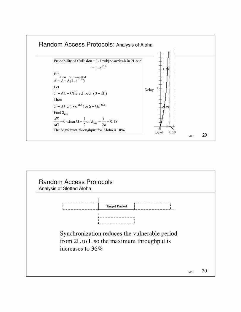
Random Access Protocols: Analysis of Aloha
Load
Delay
0.18
New Retransmitted
30MAC
Random Access ProtocolsAnalysis of Slotted Aloha
Synchronization reduces the vulnerable period
from 2L to L so the maximum throughput is
increases to 36%
Target Packet

31MAC
Random Access ProtocolsPerformance of Unslotted and Slotted Aloha
From: “Computer Networks, 3rd Edition, A.S. Tanenbaum. Prentice Hall, 1996
32MAC
Random Access ProtocolsCSMA Protocols
� Listen to the channel before transmitting to reduce the vulnerable period
� Let D = maximum distance between nodes (m)� Let R = the transmission rate (b/s)� Let c = speed of light = 3 x 10⁸m/s� The propagation time = D/(kc)=τ (sec)
k is a constant for the physical media: k = .66 for fiber, k=.88 for coaxExample: 1 km- Free space propagation time = 3.33 us- Fiber propagation time = 5.05 us- Coax propagation time = 3.79 us

33MAC
Random Access ProtocolsCSMA Protocols
� Assume node A transmits at time t and node B at t -x, where x � 0(That is, Node B transmits right before it hears A)
� If after 2D/kc sec. no collision occurred, then none will occur
� Let a= τ/X=(D/kc)/X = normalized length of the bus
� Remember X(sec) = L/R(Packet Length [bits])/R [b/s]
� As a --> 1, CSMA performance approaches Aloha performance
34MAC
Random Access ProtocolsCSMA Protocols
� Limits on a=relative size of the network
�Want a small to keep vulnerable period short by having:
–Short bus
–Lower speeds
–Long packets
� Lower limit (Minimum) packet length to upper bound a
�Maximum packet length to be fair
a= DR/L(kc)whereL= packet length in bitsc= 3x10⁸m/sk= media prop. constant
Reason for Minimum/Maximum Packet Size in the Internet

35MAC
Random Access ProtocolsPerformance
From: “Computer Networks, 3rd Edition, A.S. Tanenbaum. Prentice Hall, 1996
Ideal
36MAC
Random Access ProtocolsPerformance: Nonpersistent CSMA
0.81
0.51
0.14
S
G
0.01
0.1
1
From: Leon-Garcia & Widjaja: Communication Networks

37MAC
Polling vs Random Access Performance
α= aN=# Nodes
38MAC
Random Access ProtocolsCSMA Protocols: States
From: “Computer Networks, 3rd Edition, A.S. Tanenbaum. Prentice Hall, 1996

39MAC
Collision Free Protocols
� Collision free protocols establish rules to determine which stations sends after a successful transmission.
� Assume there are N stations with unique addresses 0 to N-1.
� A contention interval is a period after a successful transmission that is divided into N time slots, one for each station.
40MAC
Collision Free Protocols
� If a station has a PDU to send it sets a bit to 1 in its time slot in the contention interval.
� At the end of the contention interval all nodes know who has data to send and the order in which it will be sent.

41MAC
Collision Free Protocols
� Problems:�Fairness
�Flexibility
�Many systems use the basic approach of collision free protocols
42MAC
Random Access and Reservations
� Distributed systems: Stations implement a decentralized algorithm to determine transmission order, e.g., reservation Aloha
� Centralized systems: A central controller accepts requests from stations and issues grants to transmit� Frequency Division Duplex (FDD): Separate frequency bands for uplink & downlink
� Time-Division Duplex (TDD): Uplink & downlink time-share the same frequency channel
� The centralized system is used in many access technologies, e.g.,� DOCSIS� IEEE 802.16 (WiMAX)� Wideband code division Multiple access (WCDMA)
�High Speed Data Packet Access (HSDPA) - Evolution from GSM� Long Term Evolution (LTE)� CDMA2000
� Evolution Data optimized EV-DO – Evolution from CDMA
Adapted from: Leon-Garcia & Widjaja: Communication Networks

43MAC
Reservation System
� System Characteristics
�Asymmetric
– Upstream� Minislots with requests for resources
� Access Minislots via random access protocol
– Downstream� Accepts minislots and includes grants for transmission on the upstream
� Grants control the flow on the upstream link
� Order of grants established via a “scheduling” algorithm
44MAC
Reservation Systems
Time
Cycle n
Reservation
interval
Frame
transmissions
r d d d r d d d
Cycle (n + 1)
r = 1 2 3 M
� Transmissions organized into cycles (or frames)
� Cycle: reservation interval + frame transmissions
� Reservation interval has a minislot for each station to request reservations for frame transmissions; minislot can carry other information, e.g., number of frame to TX, station backlog, channel quality indicator (CQI)
Adapted from: Leon-Garcia & Widjaja: Communication Networks
Upstream Transmissions
Minislot

45MAC
Central controller issues grants to
transmit
� Algorithms to grant permission to UE permission to transmit on upstream can be based on:
� number of frame to TX,
� station backlog,
� channel quality indicator (CQI)
– Leads to Opportunistic Scheduling
�Other…..
46MAC
Throughput� Let
� R = Link rate (b/s)
� L = packet size (bits)
� v= minislot size (sec)
� M = Number of stations
� X = L/R (sec)
� Assume� Propagation delay < X � Access network
� Heavy load � stations have packets to send
� All requests are granted
� One minislot needed for each packet/station
� Time to transmit M packets = Mv+MX
Adapted from: Leon-Garcia & Widjaja: Communication Networks

47MAC
Throughput
� If k frame transmissions can be reserved with ONE reservation message and if there are M stations, as many as Mk frames can be transmitted in XM(k+v) seconds
Adapted from: Leon-Garcia & Widjaja: Communication Networks
48MAC
Throughput: with random access
contention for Minislots
� Real systems have too many nodes for each to get a fixed minislot.
� Therefore a random access protocol is used to transmit in a minslot.� A station attempts to obtain a grant by transmitting in a minslot in the upstream direction.
� If successful the station will get the grant on the down stream
� If unsuccessful then assume collision, backoff and retry. Here unsuccessful means that the station did not see a grant in corresponding the down stream information.

49MAC
Throughput: with random access contention for Minislots
� Assume slotted Aloha is used for contention for minislots.
� On average, each reservation takes at least e = 2.71 minislot attempts
� Effect is just to make the minislots seem longer
1
1 + 2.71v/XSmax =
50MAC
Standard LANs
� IEEE 802.3 [10 Mb/s]� CSMA/CD
� Baseband
� IEEE 802.4 [up to 10 Mb/s]� Token Bus
� Modulated
� IEEE 802.5 [4 and 16 Mb/s]� Token ring
� Baseband
� IEEE 802.11 Wireless LAN (more later)

51MAC
Standard LANs� FDDI (CDDI) [100 Mb/s]
� Token Ring� Fiber Distributed Data Interface
� Copper Distributed Data Interface
� Baseband
� IEEE 802.12 [100 Mb/s]� Demand priority
� IEEE 802.16 (Wireless local loop or Wireless MAN)
� Other IEEE 802.xx Protocols
� Cable Modem� Data over Cable Service Interface Specification (DOCSIS)
52MAC
Standard LANs
Network LayerIEEE 802.2
Medium Access ControlPhysical Layer
IEEE 802.2 = Logical Link Control
Protocol
IEEE 802.3IEEE 802.4IEEE 802.5IEEE 802.6IEEE 802.11IEEE 802.12IEEE 802.16Others…..
53MAC
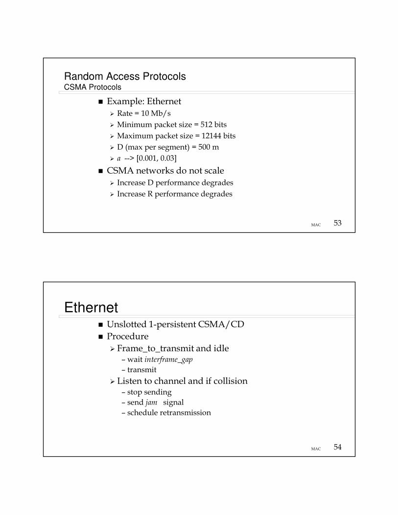
Random Access ProtocolsCSMA Protocols
� Example: Ethernet
� Rate = 10 Mb/s
� Minimum packet size = 512 bits
� Maximum packet size = 12144 bits
� D (max per segment) = 500 m
� a --> [0.001, 0.03]
� CSMA networks do not scale
� Increase D performance degrades
� Increase R performance degrades
54MAC
Ethernet� Unslotted 1-persistent CSMA/CD
� Procedure
� Frame_to_transmit and idle– wait interframe_gap
– transmit
� Listen to channel and if collision– stop sending
– send jam signal
– schedule retransmission

55MAC
Ethernet: Schedule retansmission(the binary exponential backoff algorithm)
� N= N+1 where N = number of retransmission attempts
� If N > attempt limit then trash the PDU
else calculate the backoff time
– k = Min[N, backoff_limit]
– R ~ Uniform [0, 2k]
– retransmit at time tnow +
R*slot_time
56MAC
Ethernet: Parameters
� Slot time = 512 bit times
� Interframe gap = 9.6us
� Attempt limit = 16
� Backoff limit = 10
� Jam time = 32 bits/rate
� Maximum frame size = 8*(1518) bits
� Minimum frame size = 8*(64) bits

57MAC
Ethernet
Packet structure
Preamble SDDestination
Address
Source
AddressLength Information Pad FCS
7 1 6 6 2 4
46 to 1500 bytesSynch Start
frame
802.3 MAC Frame
Preamble: 7 bytes of 10101010
Start Of Frame: 1 byte, thus: 10101011
Source and Destination Address: Each 6 bytes and are globally unique.
Type field:
In 802.3 this field gives the length (in bytes) of the data field.
Data field: From 46 to 1500 bytes.
1A-23-F9-CD-06-9B
1518 Bytes
58MAC
Ethernet: Typical Configurations
NIC NIC NIC
Bus
Hub
NIC NIC
NIC
NIC = Network Interface Card
Started here
Evolved to

59MAC
Switched Ethernet
AHigh Speed Interface, GigE
From: “Computer Networks, 3rd Edition, A.S. Tanenbaum. Prentice Hall, 1996
60MAC
Gigabit Ethernet
� Allows half- and full-duplex operation at speeds of 1000 Mb/s
� Uses the 802.3 Ethernet frame format
� Can use the CSMA/CD access method with support for one repeater per collision domain: Half-duplex
� Common use is with Gigabit Ethernet switches in Full-duplex mode→ Νo CSMA/CD
� Addresses compatibility with 10 Mb/s, 100 Mb/s, and 10-Gigabit Ethernet technologies
From: Whitepaper: Gigabit Ethernet Overview, Gigabit Ethernet Alliance, May, 1997, http://www.gigabit ethernet.org/technology/whitepapers

61MAC
Gigabit Ethernet: Distance
� Multimode fiber-optic link with a maximum length of 550 meters
� Single-mode fiber-optic link with a maximum length of 3 kilometers
� Optical links based on Fiber channel technology
� Copper based link with a maximum length of at least 25 meters.
� Category 5 unshielded twisted pair (UTP) wiring link 100 meters
From: Whitepaper: Gigabit Ethernet Overview, Gigabit Ethernet Alliance, May, 1997, http://www.gigabit ethernet.org/technology/whitepapers
62MAC
Gigabit Ethernet:
Possible Application
From: Whitepaper: Gigabit Ethernet Overview, Gigabit Ethernet Alliance, May, 1997, http://www.gigabit ethernet.org/technology/whitepapers

63MACFrom: Mike Salzman, "10 GbE requirements & architecture,"
http://grouper.ieee.org/groups/802/3/10G_study/public/june99/salzman_1_0699.pdf
Evolution of Ethernet Technology
PMD=Physical Media Dependent
64MAC
Ethernet� 40 Gb/s Ethernet 40GbE
� 100 Gb/s Ethernet 100GbE
� Provide support for optical transport network(OTN)
� Carrier Grade Ethernet
� Ethernet services to end customers
� Ethernet technology in carrier networks
Adapted from: Leon-Garcia & Widjaja: Communication Networks
Virtual LAN
65MAC
Core DWDM Optical Network
Carrier COPoP
GbE
Location B
Location A
GbE
GbE GbE
Carrier COPoP
GbE
Campus LAN
GbE
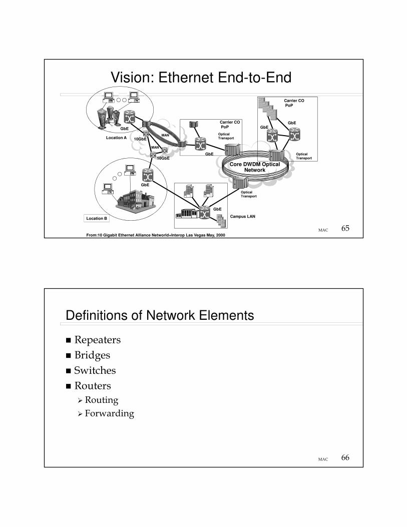
Vision: Ethernet End-to-End
MAN
MAN
10GbE
10GbE
OpticalTransport
OpticalTransport
OpticalTransport
From:10 Gigabit Ethernet Alliance Networld+Interop Las Vegas May, 2000
66MAC
Definitions of Network Elements
� Repeaters
� Bridges
� Switches
� Routers
� Routing
� Forwarding

67MAC
Repeaters & Bridges� Repeaters forwards electrical signals from one Ethernet to another
� Bridges (sometimes called hubs)
� Interconnects multiple access LANs to form Extended LANs
� Only forwards frames destined for other LANs
� Link layer forwarding based on MAC address
� Bridges are devices that forward link-level frames from one physical LAN to another
� Bridging forwarding rules prevent loops
68MAC
Switches & Routers� Switches
– Forwards packets– Star topology– New hosts can be added without degrading the performance of the existing hosts
– Scales by adding additional switches (if supported by the switch fabric)
� Routers & Gateways– Forwards packets– Interconnects two or more networks (maybe owned by different organizations)
– Forwarding� take packet from input port then use routing table to find an output port then forward packet to that port.
– Routing� process of filling in the routing table

69MAC
Switches & Routers� Layer 2 switching is performed by looking at a destination MAC address within a frame. Layer 2 switching builds and maintains a switching table that keeps track of which MAC addresses belong to each port or interface.� Ethernet switches
�ATM Switches
70MAC
Switches & Routers� Layer 3 switching (routers) operates at the network layer. It examines packet information and forwards packets based on their network-layer destination addresses.� IP Switches
� Layer 4 Switching operates at the transport layer makes forwarding decision based on IP address and TCP/UDP application port� Gateways, Firewalls, IPSec, Policy Based Networks (PBN), Directory Enabled Networks (DEN)
71MAC
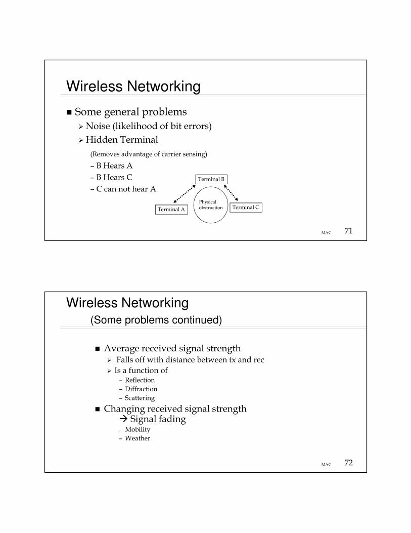
Wireless Networking
� Some general problems
�Noise (likelihood of bit errors)
�Hidden Terminal
(Removes advantage of carrier sensing)
– B Hears A
– B Hears C
– C can not hear A
Terminal A
Terminal B
Terminal CPhysical obstruction
72MAC
Wireless Networking (Some problems continued)
� Average received signal strength� Falls off with distance between tx and rec
� Is a function of – Reflection
– Diffraction
– Scattering
� Changing received signal strength � Signal fading– Mobility
– Weather

73MAC
Propagation mechanisms
R=ReflectionS=ScatteringD=Diffraction
From: Anderson, J., Rappaport, and Yoshida, S. “Propagation Measurements and Models forWireless Communications Channels,” IEEE Communications Magazine, Jan 1995
74MAC
Propagation Effects
Modified from: W. Stallings, Wireless Communications & Networks, Pearson 2005
� Signal strength at a distance varies due to Multipath
� Large scale models predicts the average signal strength
� Red line
� Small scale (fading) models characterize the short term fluctuations
� Black line

75MAC
IEEE 802.11
� Form of a packet radio network
� Must deal with the hidden terminal problem
� Physical layer
� Frequency Hopping Spread Spectrum
� Direct Sequence Spread Spectrum
� Infrared
76MAC
IEEE 802.11� MAC- Carrier Sense Multiple Access with Collision Avoidance (CSMA/CA)� Sense channel if idle the send�Request to Send (RTS) PDU
� Receiver responds with a �Clear to Send (CTS) PDU
� If receive CTS then all other nodes know the channel is captured and will not send, original sources sends without collision
� If RTS PDUs collide then use random access backoffalgorithm
� RTS/CTS deals with the hidden terminal problem
� Access Points (AP) are the wireless/wired gateways: Infrastructure mode
� Ad hoc mode

77MAC
802.11a
� 802.11a supports mandatory data rates of 6, 12, and 24 Mbps
� Optional data rates of 9, 18, 36, and 54 Mbps
� Operates in 5-GHz UNII (Unlicensed National Information Infrastructure) band
� Occupies 300 MHz in three different bandwidths of 100 MHz each:5.150 to 5.250 GHz (U-NII lower band)5.250 to 5.350 GHz (U-NII middle band)5.725 to 5.825 GHz (U-NII upper band)802.11a provides 12 channels, each channel being 20 MHz wide, and each centered at 20 MHz intervals (beginning at 5.180 GHz and ending at 5.320 GHz for the upper and middle U-NII bands, beginning at 5.745 GHz and ending at 5.805 GHz for the upper U-NII band). It is important to note that none of these channels overlap.
� 802.11a uses OFDM (Orthogonal Frequency Division Multiplexing) with multiple carriers (aka "subcarriers") per channel
Beware of the Tragedyof the Commons
78MAC
802.11b� Supports data rates of 1, 2, 5.5, and 11 Mb/s.
� Operates in the 2.4-GHz ISM (Industrial, Scientific, and Medical) band.
� Occupies 83.5 MHz (for North America) from 2.4000 GHz to 2.4835 GHz.
� 802.11b provides 11 channels (for North America), each channel being 22 MHz in width, and each channel centered at 5 MHz intervals (beginning at 2.412 GHz and ending at 2.462 GHz). This means that there are only 3 channels which do not overlap (channels 1, 6, 11).
� 802.11b uses DSSS (Direct Sequence Spread Spectrum) with a single carrier per channel.
� Both 802.11b and 802.11a use the 802.11 MAC, both use CSMA/CA to "listen" before transmitting on a given channel (to avoid colliding with another transmitter by sensing if the channel is occupied).

79MAC
802.11g
� A physical layer standard for WLANs in the 2.4GHz and 5GHz radio band.
� The maximum link rate is 54-Mbps per channel--compared with 11 Mbps for 11b.
� 802.11g standard uses orthogonal frequency-division multiplexing (OFDM) modulation but, for backward compatibility with 11b, it also supports complementary code keying (CCK) modulation and, as an option for faster link rates, allows packet binary convolutional coding (PBCC) modulation.
� Speeds similar to 11a and backward compatibility may appear attractive
� Advantage-provides ability for dual-mode 2.4GHz and 5GHz products, in that using OFDM for both modes to reduce silicon cost.
80MAC
Other IEEE 802.11 standards� IEEE 802.11n
� Increase rate to 600 Mb/s
� Used multiple antennas �Multiple-input multiple-output (MIMO)
� Frame aggregation, effectively increase packet size to reduce overhead
� IEEE 802.11ac
� Increase rate to 1 Gb/s
� 80MHz and 160 MHz channels
� Higher order modulation
� IEEE 802.11af (White-Fi) proposal for Wi-Fi using the TV White spaces using cognitive radio technology.
� IEEE 802.11ad (WiGig) enables data rates up to 7 Gb/s (uses 60 GHz spectrum)

81MAC
802.11e
� Supplementary to the MAC layer to provide CoS support for LAN applications.
� Applies to 802.11 physical standards a, b and g.
� 802.11e provides some features for differentiating data traffic streams.
82MAC
Broadband Access Technologies: Cable Modems
From: “Computer Networks, 3rd Edition, A.S. Tanenbaum. Prentice Hall, 1996
FDM on the Cable
83MAC
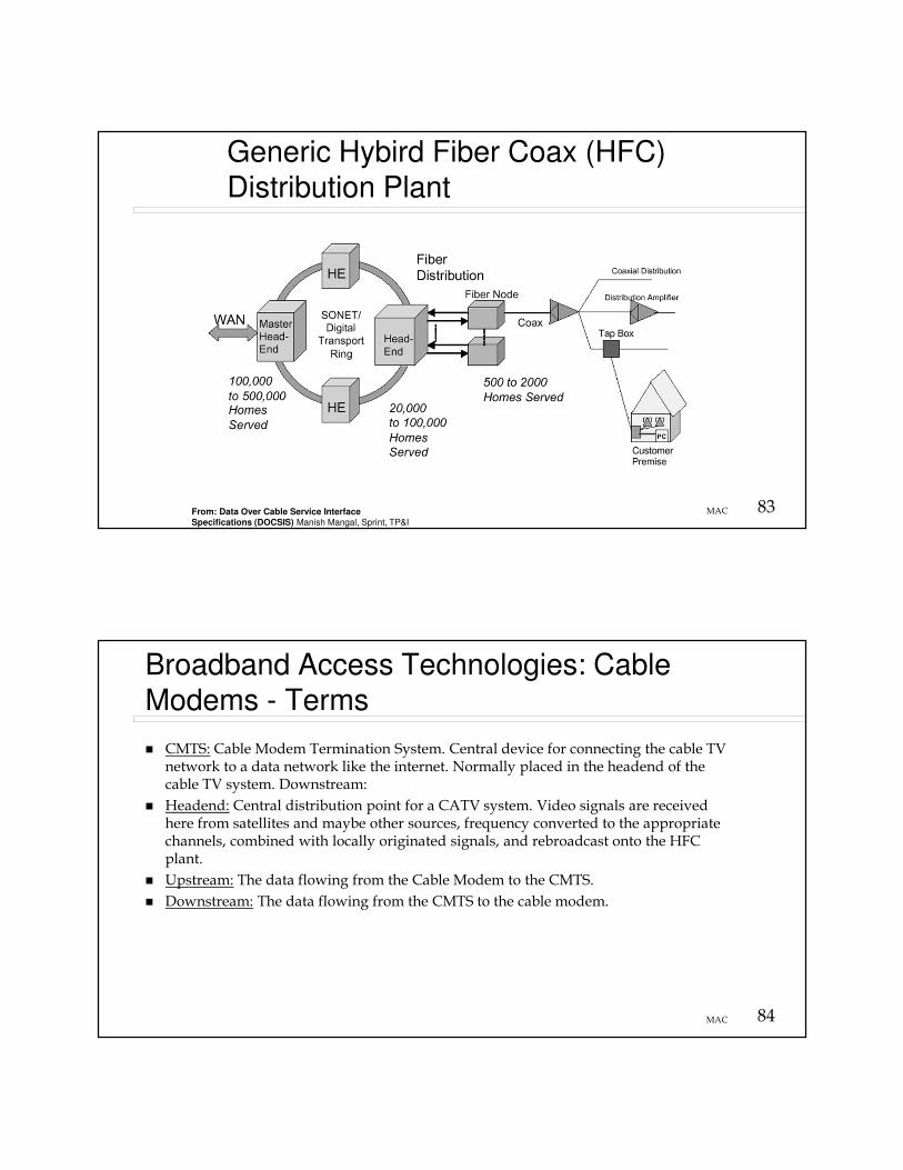
Generic Hybird Fiber Coax (HFC) Distribution Plant
From: Data Over Cable Service InterfaceSpecifications (DOCSIS) Manish Mangal, Sprint, TP&I
84MAC
Broadband Access Technologies: Cable Modems - Terms
� CMTS: Cable Modem Termination System. Central device for connecting the cable TV network to a data network like the internet. Normally placed in the headend of the cable TV system. Downstream:
� Headend: Central distribution point for a CATV system. Video signals are received here from satellites and maybe other sources, frequency converted to the appropriate channels, combined with locally originated signals, and rebroadcast onto the HFC plant.
� Upstream: The data flowing from the Cable Modem to the CMTS.
� Downstream: The data flowing from the CMTS to the cable modem.
85MAC
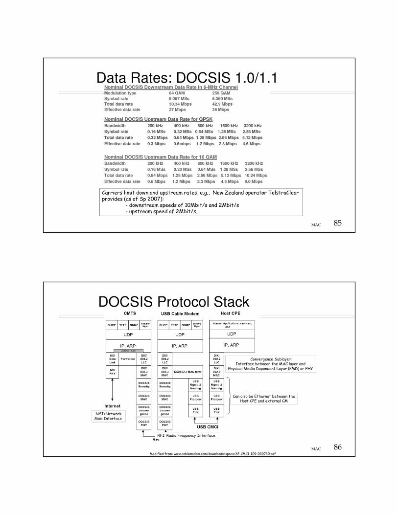
Data Rates: DOCSIS 1.0/1.1
Carriers limit down and upstream rates, e.g., New Zealand operator TelstraClear provides (as of Sp 2007):
- downstream speeds of 10Mbit/s and 2Mbit/s - upstream speed of 2Mbit/s.
86MAC
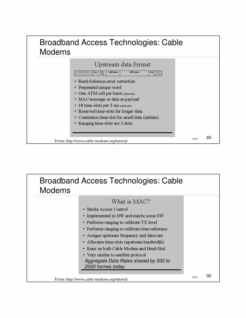
DOCSIS Protocol Stack
Modified from: www.cablemodem.com/downloads/specs/SP-CMCI-I09-030730.pdf
Can also be Ethernet between theHost CPE and external CM
NSI=NetworkSide Interface
Convergence Sublayer:Interface between the MAC layer and
Physical Media Dependent Layer (PMD) or PHY
RFI=Radio Frequency Interface

87MACFrom: “Computer Networks, 3rd Edition, A.S. Tanenbaum. Prentice Hall, 1996
Broadband Access Technologies: Cable Modems - Terms
Headend controls all transmissions on the downstream and schedules upstream
Request for use of upstream made using random access (contention) in specific upstream time slots
88MAC
Broadband Access Technologies: Cable Modems
From: http://www.cable-modems.org/tutorial
89MAC
Broadband Access Technologies: Cable Modems
From: http://www.cable-modems.org/tutorial
90MAC
Broadband Access Technologies: Cable Modems
From: http://www.cable-modems.org/tutorial
Aggregate Data Rates shared by 500 to
2000 homes today
91MAC
DOCSIS MAC� Data Over Cable Service Interface Specification
(DOCSIS)
� A stream of mini-slots in upstream (6.25 us containing 8-32 Bytes)
� Dynamic mix of contention- and reservation-based upstream transmit opportunities
� Quality of service including:� Support of Bandwidth and Latency guarantees
� Packet classification
� Dynamic service establishment
� Extensions provided for security at data link layer
� Support of wide range of data rates
92MAC
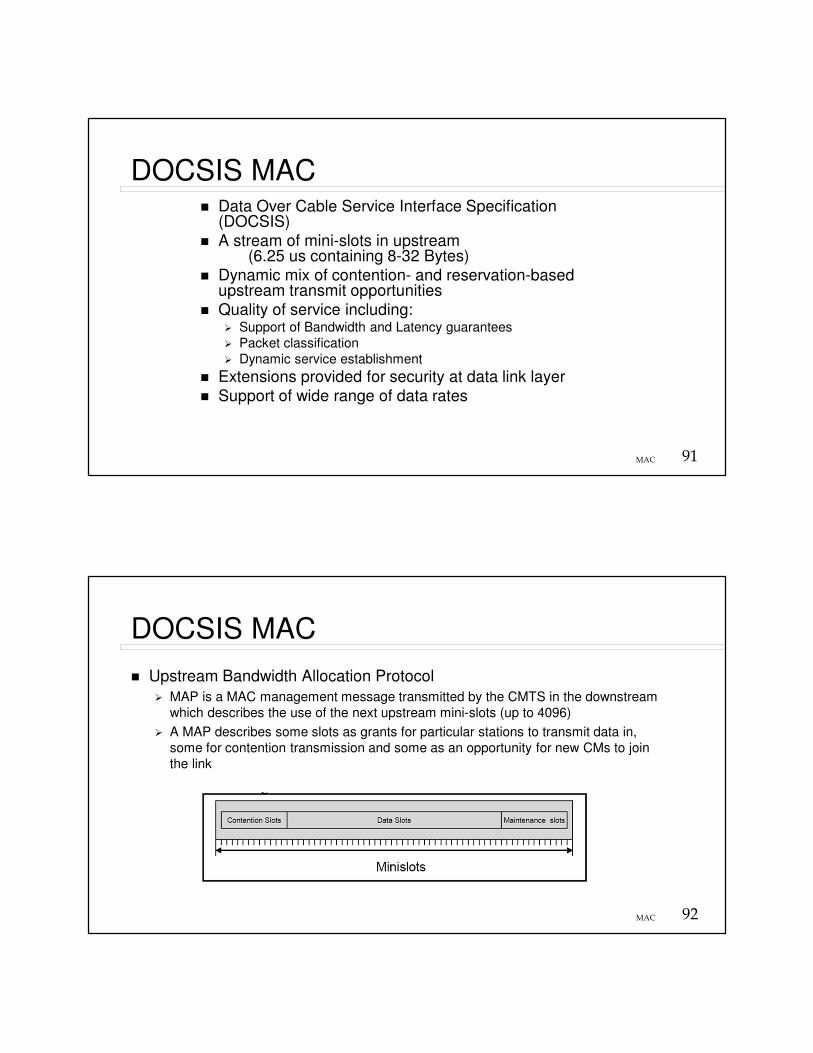
DOCSIS MAC
� Upstream Bandwidth Allocation Protocol
� MAP is a MAC management message transmitted by the CMTS in the downstream
which describes the use of the next upstream mini-slots (up to 4096)
� A MAP describes some slots as grants for particular stations to transmit data in,
some for contention transmission and some as an opportunity for new CMs to join
the link
93MAC
DOCSIS MAC
From: Data Over Cable Service InterfaceSpecifications (DOCSIS) Manish Mangal, Sprint, TP&I
94MAC
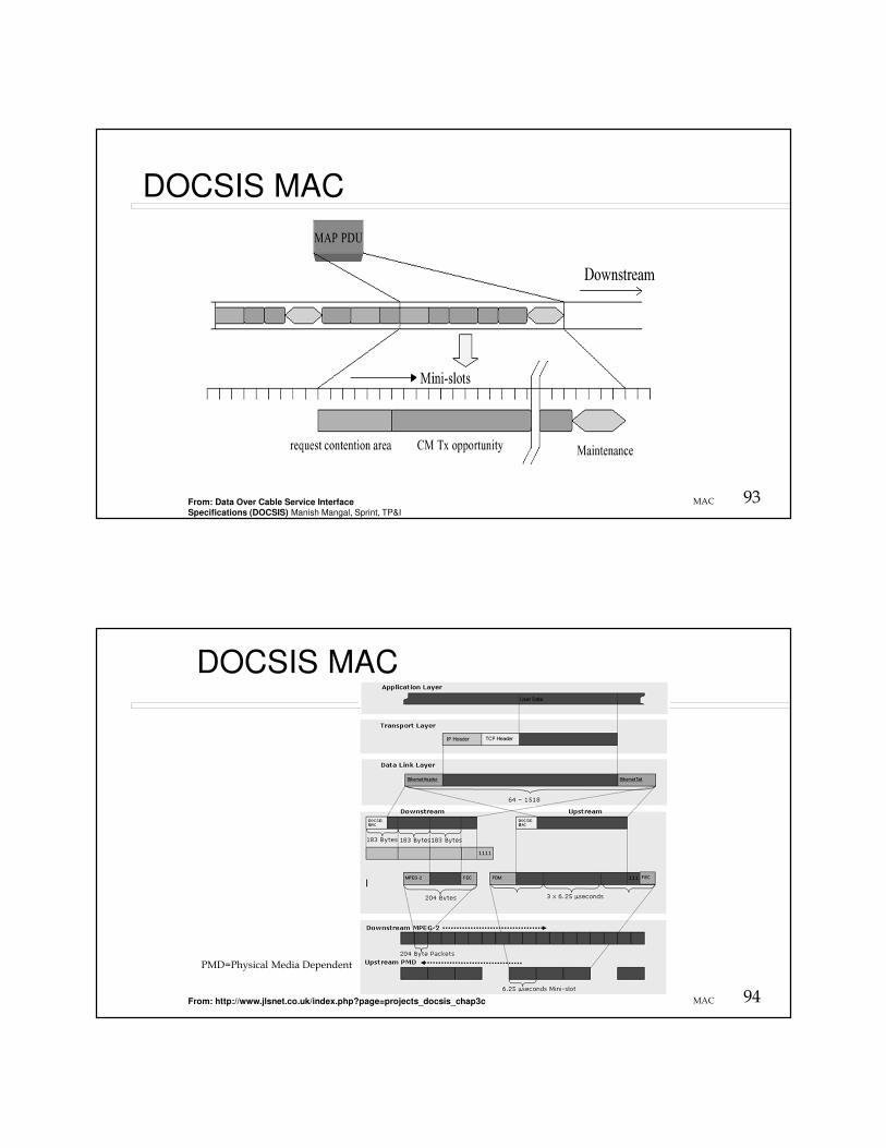
DOCSIS MAC
From: http://www.jlsnet.co.uk/index.php?page=projects_docsis_chap3c
PMD=Physical Media Dependent
95MAC
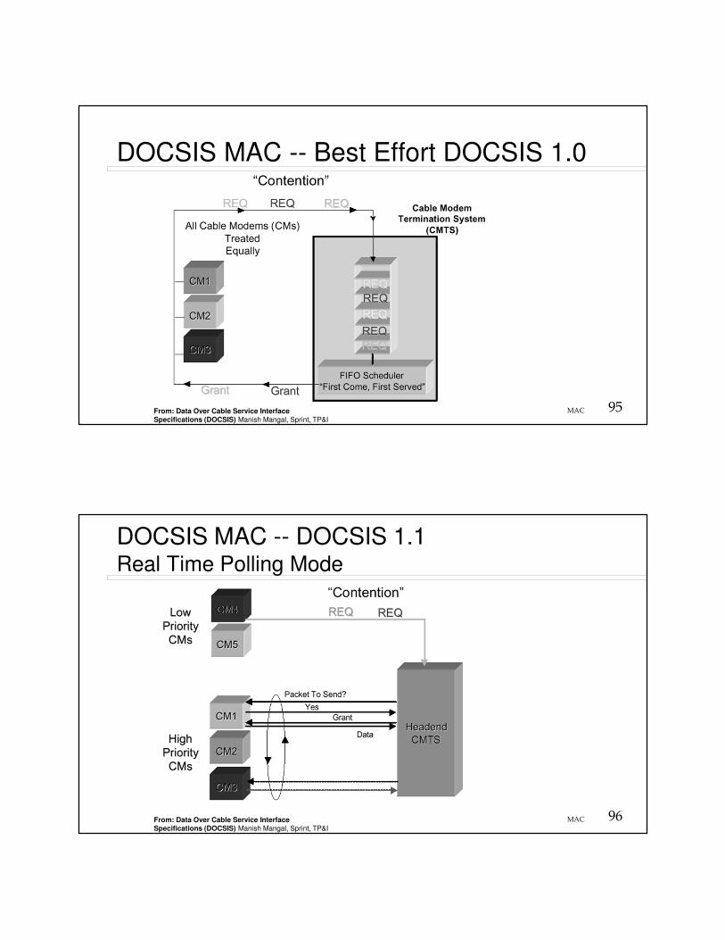
DOCSIS MAC -- Best Effort DOCSIS 1.0
From: Data Over Cable Service InterfaceSpecifications (DOCSIS) Manish Mangal, Sprint, TP&I
96MAC
DOCSIS MAC -- DOCSIS 1.1Real Time Polling Mode
From: Data Over Cable Service InterfaceSpecifications (DOCSIS) Manish Mangal, Sprint, TP&I

97MAC
DOCSIS MAC -- DOCSIS 1.1Circuit Switched Emulation “Unsolicited Grant Mode”
From: Data Over Cable Service InterfaceSpecifications (DOCSIS) Manish Mangal, Sprint, TP&I
98MAC
Evolution of DOCSIS
� Embedded DOCSIS: eDOCSIS device contains
� CM
� One or more embedded Service/Application Functional Entities (eSAFEs)– Telephone
– Video
– Audio
– Digital video recorders
– Multiple TV tuners

99MAC
DOCIS 3.0
From: http://www.fttxtra.com/hfc/docsis/docsis-3-0-tutorial/
100MAC
DOCSIS 3.0: Channel Bonding
From: http://www.fttxtra.com/hfc/docsis/docsis-3-0-tutorial/

101MAC
Wireless broadband Internet
IEEE 802.16 (WiMax)
IEEE 802.16 protocol based on DOCSISIEEE 802.16e addresses mobility
102MAC
Digital Subscriber Line: Physical topology
Telephone Lines
� NID = Network Interface Device
� DSLAM= Digital Subscriber Line Access Multiplexer
Modified from: Tanenbaum, A. Computer Networks, Prentice Hall, 4th ED 2003

103MAC
Broadband Access Technologies:DSL - digital subscriber line
� Not shared media
� Point-to-point connection to network
� ADSL - Asymmetric DSL�Downstream - 1.5 Mb/s - 9 Mb/s
�Upstream - 16 kb/s - 640 kb/s
� HDSL - High data rate DSL�Downstream - 1.5 Mb/s - 2 Mb/s
�Upstream - 1.5 Mb/s - 2 Mb/s
104MAC
Broadband Access Technologies:DSL - digital subscriber line
� VDSL - Very high data rate DSL� Downstream - 13 Mb/s - 52 Mb/s
� Upstream - 1.5 Mb/s - 2.3 Mb/s
� G.lite officially ITU-T standard G-992.2
� Downstream - 1.544 Mb/s to 6 Mb/s
� Upstream - 128 Kbps to 384 Kbps
� Does not require splitting of the line at the user end
� DSLAM - digital subscriber line access multiplexer
� Speed depends on distance from DSLAM (max 18,000 ft)
105MAC
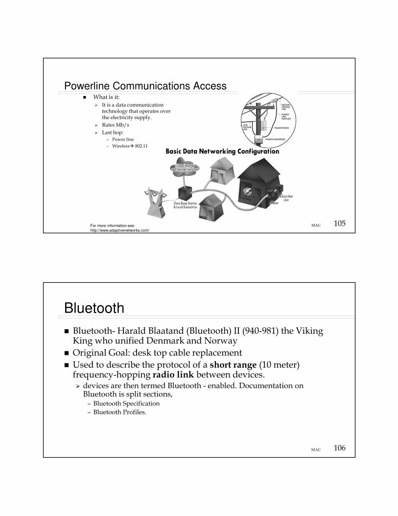
Powerline Communications Access
For more information see:
http://www.adaptivenetworks.com/
� What is it:
� It is a data communication technology that operates over the electricity supply.
� Rates Mb/s
� Last hop:
– Power line
– Wireless� 802.11
106MAC
Bluetooth
� Bluetooth- Harald Blaatand (Bluetooth) II (940-981) the Viking King who unified Denmark and Norway
� Original Goal: desk top cable replacement
� Used to describe the protocol of a short range (10 meter) frequency-hopping radio link between devices. � devices are then termed Bluetooth - enabled. Documentation on Bluetooth is split sections, – Bluetooth Specification
– Bluetooth Profiles.

107MAC
Bluetooth
� The Specification describes how the technology works (i.e the Bluetooth protocol architecture),
� The Profiles describe how the technology is used (i.e how different parts of the specification can be used to fulfill a desired function for a Bluetooth device)
� Uses frequency hopping in 79 hops displaced by 1 MHz, starting at 2.402GHz and finishing at 2.480GHz
� Data Rate < 1Mb/s
For more details see:http://www.palowireless.com/infotooth/tutorial.asp
108MAC
RFID
� Radio Frequency Identification Tags� Replacement for Barcode� Types
� Active (like Kansas Turnpike K-tag)� Passive
� Need MAC when reading a group of products at “once”� Issues
� Cost� Privacy

109MAC
Satellite Networks: GEO
�Geostationary earth orbit
�37,700 km
�Power--> increased cost
�Propagation delay
�Limited orbital slots ~ 180(2 degrees)
110MAC
Satellite Networks: MEO
�Medium earth orbit
� 5,000 - 15,000 km
� Period ~ 4-9 hours
� Fewer satellites

111MAC
Satellite Networks: LEO
� Low earth orbit
� 1500 km
� Periods up to 2 hours
� More satellites
� Cheaper to launch
Odyssey Telecommunications International Inc.:Worldwide Personal CommunicationsSatellite Services
112MAC
Satellite Networks� Properties
� Large delay ~ 270 ms (Geosynchronous)
� Up and down links are on different frequencies
( full duplex)
� CSMA/CD will not work because of long delay
� Token networks are not applicable because of long delays, e.g., 100 nodes will have a 27 sec. token return time.

113MAC
Satellite Networks: Reservation ALOHA
� Consider a slotted system with N slots per frame (TDM like)
� Each slot can be in one of three states:– Empty, i.e., not is use
– Mine, i.e., in use by me
– Other, i.e., in use by another node
� Protocol– If state is mine then continue to use it
– If state is other then do not send in that time slot
– If state is empty then contend for that slot using Aloha
114MAC
Satellite Networks
� At low loads the network performs like a random access systems, i.e., no waiting for permission to send.
� At high loads the systems performs like a TDM system.
� This scheme has a problem with fairness
� Distributed assignment of time slots

115MAC
Satellite Networks� TDMA - Time Division Multiple
Access
� Up stream stations request bandwidth, time slots.
� Central controller grants requests for bandwidth
� Central controller has global view of all requests
� Centralized assignment of time slots
116MAC
Satellite Access
� What it is: Satellite access
� Typically Asymmetric
Features
DirecWay Starband
Basic Plus Starband
360
Starband
481
Upload speed 50 Kbps 100 kbps 50 Kbps 100 Kbps
Download
speed
500 Kbps 500 Kbps 500 Kbps 500 Kbps
Equipment cost $600 $600 $700 $700
Installation cost $400 $400 $400 $400
Monthly cost $60 $100 $60 $90
Contract term 2 yr 2 yr 1 yr 1 yr
IP address NAT Static NAT Static
Installation
training
and cert.
1 day training in Ohio
conducted last
Saturday of every
month. Cost $500
Training and test available
online, free of charge
As of 2005

117MAC
Nelson Environmental Study Area (NESA) Wireless Data Link
NESA HQ – Flux Tower Network
118MAC
Satellite Link Bandwidth Tests
Microsoft Remote Desktop was used to access the data server PC located in the NESA HQ building, then
internet access bandwidth tests were initiated. Remote Desktop has a significant impact on the available
bandwidth reported. Typical numbers directly from the NESA site are 1440 kbps up / 700 kbps down.


