
Medfusion® - medonegroup.com · Introduction 40-5648-51C 1 Important Information WARNING: Read...
184
s Medfusion® 3000 Series Technical Service Manual
Transcript of Medfusion® - medonegroup.com · Introduction 40-5648-51C 1 Important Information WARNING: Read...

s
Medfusion®3000 Series
Technical Service Manual

Table of Contents
ii 40-5648-51C

Table of Contents
iii40-5648-51C
Table of ContentsI Introduction 1Important Information 1Warnings.................................................................................... 1Cautions..................................................................................... 2
Contents of this manual 3Authorized.use.of.this.manual................................................ 3
About the pump 4Features.and.Controls.............................................................. 4
Keypad.closeup................................................................... 5
Understanding “Biomed” mode 7What.is.biomed?....................................................................... 7Authorized.biomed.access....................................................... 7Biomed.software.program.–.major.options.......................... 7Symbols...................................................................................... 8Glossary.of.Technical.Terms................................................... 9
Preventive Maintenance Planning 15
Biomed maintenance tools 15Using.a.torque.screwdriver................................................... 15Electrostatic-controlled.workstation................................... 15
II Scheduled Maintenance 15Service.warnings............................................................... 16
Periodic maintenance 17Installation/quick.check-out................................................. 17
Quick.check-out.test........................................................ 17Cleaning.and.care................................................................... 18
Standard.cleaning.of.Medfusion®.3000.series.pumps.. 18Cleaning.cautions............................................................. 18
Mandatory annual maintenance testing 19
General.inspection................................................................. 19Power-up.test.......................................................................... 19Calibration.verification.......................................................... 20
Force.sensor.check............................................................ 20Syringe.size.sensor.check................................................. 20Plunger.position.sensor.check........................................ 21Motor.drive.&.occlusion.operational.test...................... 21Flow.delivery.accuracy.test.............................................. 22AC.line.leakage.test.......................................................... 22
AC.line.leakage.test.-.Medfusion® 3500BC ............ 23Battery.maintenance.............................................................. 24
Shallow.discharge.(CPI).record...................................... 24Battery.calibration.procedure......................................... 24Requirements.for.battery.pack.replacement................. 25
Collect.Separately......................................................... 25
Overview of operation 27Controlling.motor.functions................................................. 27Infusion.control.&.safety.functions..................................... 27
III Theory of Operation 27Pump design description 28Logic.core.of.Medfusion®.3000.Series.pumps..................... 28Main.circuit.board.................................................................. 28
Main.microprocessor....................................................... 28Watchdog.circuit............................................................... 29DC.power.converter......................................................... 29Real.time.clock.................................................................. 29Graphical.display.circuit.board.(LCD).......................... 29Keypad............................................................................... 29Plunger.(driver).travel.sensor......................................... 29Motor.rotation.sensor...................................................... 29Stepper.motor.................................................................... 29Syringe.flange.loaded.sensor........................................... 29Syringe.size.sensor............................................................ 29Interconnect.printed.circuit.board................................. 29AC.power.input.&.power.supply.board......................... 30DC.power.input.jack........................................................ 30Speaker............................................................................... 30Rechargeable.battery.pack.&.battery.gauge.................. 30Plunger.printed.circuit.board.......................................... 30
Plunger.force.sensor.................................................... 30Plunger.Loaded.Sensors.............................................. 30
Main.Board.–.Schematic.Level............................................. 31Logic.Kernel.Description................................................. 31
68HC11K4.Main.Microprocessor.Interface,.U19.... 31Flash.memory,.U22...................................................... 34Software.upgrade.method.for.programming..
flash..memory..................................................................... 34
Static.random.access.memory,.U17........................... 34Serial.EEPROM,.U2.and.U4....................................... 34Time.of.day,.U8............................................................ 34Infrared.transceiver..................................................... 34Analog.to.digital.converter,.U13................................ 35Digital.to.analog.converter,.U20................................ 35
I/O.port.expansion,.U3,.U33................................................ 36Expansion.port.#.1.(port1_cs)...................................... 36Expansion.port.#.2.(port2_cs)...................................... 37Power.control.description............................................... 38
Always.on.supply,.U7.................................................. 38Backup.super.capacitor,.C11....................................... 38Backup.audio.buzzer,.XD1.......................................... 38System.reset,.U43......................................................... 39Power.management,.U39............................................ 39Power.OFF.state........................................................... 39Power.ON.state............................................................. 39Watchdog...................................................................... 39
DC.to.DC.converter......................................................... 40Logic.supply,.U12......................................................... 40Motor.supply,.U34....................................................... 40Analog.supply,.U21...................................................... 40Positive.&.negative.supply,.U36................................. 41

Table of Contents
iv 40-5648-51C
LCD.backlight.supply,.U1........................................... 41Front.panel.interface.description................................... 42
LED.drive.circuit,.Q26,.Q27,.Q40,.Q33.-.Q37......... 42Keypad.matrix.interface.............................................. 42Power.switch.interface................................................. 42
Graphic.display.interface.description............................ 43Data.output.to.LCD,.U32./.data.input.from..
LCD,.U6..................................................................... 43LCD.contrast................................................................ 43LCD.backlight.............................................................. 43
Motor.drive.description................................................... 44Coil.A.&.B.PWM.current.references......................... 44Motor.current.regulators,.U26,.U35.......................... 44Motor.current.detector,.U40....................................... 44
Sensors.interface.description.......................................... 45Motor.speed.detection................................................. 45Syringe.sensing.description........................................ 45Syringe.size.sensing..................................................... 45Syringe.flange.(ear).sensing........................................ 45
Plunger.position.sensing.description............................. 46Speaker.drive.description............................................ 46Speaker.control............................................................. 46Speaker.test................................................................... 47
Plunger.board.–.schematic.level........................................... 47Force.preamplifier.function............................................. 47Force.sensing.interface.description................................ 47
Plunger.flipper.sensor.function.................................. 48Interconnect.board.–.schematic.level.................................. 49
AC.power.detection.description..................................... 49External.DC.power.conditioning./.detection..
description.................................................................... 50Infrared.serial.data.port.description.............................. 50Battery.management.description.................................... 51
Battery.gauge.interface................................................ 51Battery.charger............................................................. 51Charge.detector............................................................ 52Battery.switchover........................................................ 52
Battery.board.–.schematic.level............................................ 52Battery.gauge.function..................................................... 52Severely.depleted.battery.monitor.................................. 52
Problem solving alarms / alerts 53Types.of.alarms./.alerts.......................................................... 53
IV Troubleshooting 53Alarm.messages.&.priorities................................................. 54
System.Advisory.Alarms.................................................. 60System.Failure.Alarms..................................................... 61
General.troubleshooting........................................................ 65
Smiths Medical service and support 67Using.Smiths.Medical.service.assistance............................. 67Returning.a.pump.for.repair................................................. 67
Using Biomed for troubleshooting 68Accessing.Biomed.................................................................. 68
Biomed.>.Calibration.................................................. 69Biomed.>.Diagnostics.(screen.1.of.2)........................ 69
Audio.Test..................................................................... 69Display.Test................................................................... 69Indicator.Test................................................................ 69Keypad.Test................................................................... 70Monitor.Analog.Sensors............................................. 70Monitor.Digital.Sensors.............................................. 70Monitor.Battery.Status................................................ 70Drive.Train.Test............................................................ 70
Biomed.>.Diagnostics.(screen.2.of.2)........................ 70Motor.Drive.Test.......................................................... 71Monitor.a2d.Selftest..................................................... 71Monitor.6811.a2d.Group1.......................................... 71Monitor.6811.A2D.Group2........................................ 71
Biomed.>.Utilities......................................................... 71Set/View.Last.[Next].PM.Date................................... 71Set.Time/Date.(Current)........................................... 72View.Alarm.History..................................................... 72View.Infusion.History................................................. 72View.Software.CRCs.&.View.Software.
Versions................................................................... 72View.Service.Data........................................................ 72
View.EEPROM.Size.[available.only.on.Medfusion®.3500.pumps.version.4.and.higher)........................... 72
Biomed.>.Update.Firmware.[not.available.on.Medfusion®.3500.pumps,.version.4.and.higher]...... 73
Set.Language.[Not.available.on.Medfusion®.3010..and.3010a]..................................................................... 73
Maintenance warnings/cautions 75Service.warnings..................................................................... 75Service.cautions...................................................................... 75
V Parts Replacement 75Opening & closing the pump housing 76Tools.needed........................................................................... 76Opening.the.pump.housing.................................................. 76Closing.the.pump.housing.................................................... 76
Battery pack 77Tools.needed........................................................................... 77Removing.the.battery.pack................................................... 77Replacing.the.battery.pack.................................................... 77
Verifying.battery.function.after.new.battery.replacement................................................................... 77
Interconnect board 78Tools.needed........................................................................... 78Removing.the.interconnect.board........................................ 78Replacing.the.interconnect.board........................................ 78
Verify.interconnect.board.function................................ 78
Speaker 78Tools.Needed........................................................................... 78Speaker.removal..................................................................... 78Speaker.replacement.............................................................. 78
Verifying.speaker.function.............................................. 78

Table of Contents
v40-5648-51C
AC power supply 79Tools.needed........................................................................... 79Removing.AC.power.supply................................................. 79Replacing.the.AC.power.supply........................................... 79
Verify.AC.power.supply.function................................... 79
AC input assembly 79Tools.Needed........................................................................... 79Removing.AC.input.module.assembly................................ 79Replacing.AC.input.module.assembly................................. 79
Verifying.AC.input.assembly.module.function............ 80
Bottom housing plastic 80Tools.Needed........................................................................... 80Removing.the.bottom.housing............................................. 80Replacing.the.bottom.housing.............................................. 80
Main board 81Tools.needed........................................................................... 81Removing.the.main.board..................................................... 81Replacing.the.main.board..................................................... 81
Drive train assembly 82Tools.Needed........................................................................... 82Motor.unit.(motor,.worm,.worm.gear)............................... 82
Removal............................................................................. 82Replacement...................................................................... 82
Reassemble.motor.unit................................................ 82Position.potentiometer.................................................... 83
Removal......................................................................... 83Replacement................................................................. 83
Clutch assembly 84Tools.needed........................................................................... 84Leadscrew................................................................................ 84
Removal............................................................................. 84Replacement...................................................................... 84
Clutch.or.clutch.cam.............................................................. 84Tools.needed...................................................................... 84Removal............................................................................. 85Replacement...................................................................... 85
Plunger.cable........................................................................... 85Removal............................................................................. 85Replacement...................................................................... 85
LCD and backlight 86Tools.Needed........................................................................... 86Removing.LCD.and/or.backlight.assembly........................ 86Replacing.the.LCD.and/or.backlight.assembly.................. 86
Verify.LCD.&.backlight.assembly.function.................. 87
Keypad 87Tools.needed........................................................................... 87Removing.the.keypad............................................................ 87Replacing.the.keypad............................................................. 88
Syringe barrel clamp assembly 88Tools.Needed................................................................ 88
Barrel.clamp.head................................................................... 88Removal............................................................................. 88Replacement...................................................................... 88
Verify.Function............................................................ 88Barrel.clamp.body.assembly.................................................. 88
Removal............................................................................. 88Replacement...................................................................... 89
Ear clip, handle & guide 89Tools.Needed........................................................................... 89Ear.clip..................................................................................... 89
Removal............................................................................. 89Replacement...................................................................... 89
Ear.clip.optical.sensor............................................................ 89Removal............................................................................. 89Replacement...................................................................... 90
Handle...................................................................................... 90Removal............................................................................. 90Replacement...................................................................... 90
Tubing.guide........................................................................... 90Removal............................................................................. 90Replacement...................................................................... 91
Plunger case assembly 91Tools.needed........................................................................... 91Plunger.lever........................................................................... 91
Removal............................................................................. 91Replacement...................................................................... 91
Plunger.case.disassembly....................................................... 91Disassembly....................................................................... 91Reassembly........................................................................ 91
Cam.gear.and.timing.plate.................................................... 92Removal............................................................................. 92Replacement...................................................................... 92
Flipper.and.flipper.gear......................................................... 92Removal............................................................................. 92Replacement...................................................................... 92
Plunger.board.......................................................................... 92Additional.tools.needed................................................... 92Removal............................................................................. 92Replacement...................................................................... 93
Force.sensor............................................................................ 93Additional.tools.needed................................................... 93Removal............................................................................. 93Replacement...................................................................... 93
Left.plunger.case..................................................................... 94Additional.tools.needed................................................... 94Removal............................................................................. 94Replacement...................................................................... 94
Using Biomed > CaliBration 95Biomed.>.Calibration........................................................ 95
VI Calibration and Adjustment 95Calibrate.(Syringe).size.and..
position......................................................................... 97Performing.both.size.&.position..
calibration..................................................................... 97

Table of Contents
vi 40-5648-51C
Calibrate.force.sensor.......................................................... 100Calibrate.pressure.sensor..
(future.option)........................................................... 102Calibrate.plunger.position................................................... 102Calibrate.syringe.size.sensor............................................... 104Adjust.contrast.(voltage).setting......................................... 105View.calibration.data........................................................... 106Save.changes.and.exit........................................................... 107
Exit.calibration.without.saving.changes...................... 107
Retest guidelines 108
System layout 111
VII Schematics & PCB Assemblies 111
Main board schematics 112Main.board./.logic.kernel.................................................... 112Main.Board../.Power.Control.Logic.Core......................... 116Main.Board../.DC-DC.Converter...................................... 118Main.Board./.Keypad.Interface.......................................... 120Main.Board./.Graphic.Display.Interface........................... 123Main.Board./.Motor.Drive.................................................. 124Main.Board./.Syringe.Sensing............................................ 125Main.Board./.Position.Sensing........................................... 126Main.Board./.Force.Sensing................................................ 127Main.Board./.Pressure.Sensing........................................... 128Main.Board./.Speaker.Drive............................................... 129Main.Board./.ACU-ICE.Socket.......................................... 130Main.Board.Assembly.Drawing.–.Top.Side...................... 131
Main.Board.Assembly.Drawing.–.Bottom.Side.......... 132Main.Board.Assembly.–.Parts.list...................................... 133
Plunger Board Schematic 139Plunger.Board./.Force.Preamplifier................................... 139Plunger.Board./.Flipper.Sensor.......................................... 140
Plunger.Board.Assembly.Drawing............................... 141Plunger.Board.Assembly.–.Parts.list.................................. 142
Battery Gauge Schematic 143
Interconnect Board Schematic 144Interconnect.Board./.Power.Control................................. 144Interconnect.Board./.Battery.Management...................... 145Interconnect.Board./.Infrared.Serial..
Communications...................................................... 146Interconnect.Board.Assembly.Drawing............................ 147Interconnect.board.assembly.–.parts.list........................... 148
Assembly drawings 151
VIII Assembly Drawings & Parts Lists 151
Medfusion®.3000.series.main.pump.assembly.................. 152Medfusion®.3000.series.main.pump.assembly.–..
parts.list....................................................................... 153Case.bottom.assembly......................................................... 154
Case.bottom.assembly.–.parts.list................................ 155Case.top.assembly.w/plunger.............................................. 156
Case.top.assembly.w/plunger.–.parts.list.................... 157Case.top.assembly.without.plunger................................... 158
Case.top.assembly.without.plunger.–.parts.list.......... 159Barrel.clamp.assembly......................................................... 161
Barrel.clamp.assembly.–.parts.list................................ 162Drive.train.assembly............................................................ 163
Drive.train.assembly.–.parts.list................................... 164Clutch.assembly.................................................................... 165
Accessories – parts list 166Poleclamp.assembly............................................................. 166Poleclamp.parts..................................................................... 167Rotating.poleclamp.parts.................................................... 167Miscellaneous.parts.............................................................. 167Calibration.&.repair.–.parts.list.......................................... 168
Medfusion®.3000.series.calibration.kit......................... 168Other.tools.&.equipment.required.to.service.
Medfusion®.3000.series.pumps................................. 168
Notes 169

Introduction
140-5648-51C
Important InformationWARNING: Read this entire manual before attempt-ing and service or repair on a Medfusion® 3000 Se-ries Syringe Infusion Pump. Failure to follow the instructions and important information contained in this manual, or improper/inadequate testing, service, repair or troubleshooting can lead to death or serious injury. Warnings, cautions and other im-portant safety information can be found in this sec-tion, and throughout the manual (they are contained within lines at top and bottom). The term WARNING is used to indicate a hazard that has the potential to cause injury or death to a tech-nician, patient or user. The term CAUTION is used to indicate a hazard that has the potential to cause damage to the product or other property.Note: This manual supersedes all previous revisions.
Warnings• Attempts to repair or maintain a pump by person-
nel without proper qualifications or training may create a major hazard which could result in serious injury or death to the patient or the user.
• Use only approved parts and procedures for repair and maintenance of this pump. Failure to follow this manual may create a major hazard which could result in serious injury or death to the pa-tient or the user.
• Repair Pump in ESD Controlled Work Area: The pump case should only be opened at a work-station with Electrostatic controls, including a grounded mat and wrist-strap.
• Pump Maintenance: Only trained biomedical service personnel may service this pump. Service personnel should disconnect the AC power cord before servicing the pump.
• AC Power: The only means of removing AC power is to disconnect the AC power cord. While the AC power cord is attached to the pump and plugged into an AC outlet, live mains voltage is present within the pump.
• Manufacturer Recommended Maintenance: Always maintain this pump following manufac-turer recommended instructions in this Service Manual. An improperly maintained pump may cause serious injury to a patient or user.
• Safety Class II, Type CF Medical Equipment: The
pump is listed as Safety Class II, Type CF equip-ment. Protection against electrical shock does not rely only upon basic insulation, but instead relies on double or reinforced insulation. As such, this equipment does not utilize a third wire ground (earth ground). Therefore, when doing line leak-age test it is not necessary to measure leakage in both the open ground and closed ground setting. Nor is it necessary to perform a ground resistance test.
• Safety Class II with functional earth, Type CF Medical Equipment: The pump is listed as Safety Class II with functional earth, Type CF equip-ment. Protection against electrical shock does not rely only upon basic insulation, but instead relies on double or reinforced insulation. As such, this equipment utilizes a third wire ground (earth ground) lead of the power cord as earth return for electromagnetic energy and does not serve as a safety function. Therefore it is neither possible nor necessary to perform a ground resistance test.
• Battery Replacement: Observe ESD handling precautions when replacing the battery. Replace battery only with same Smiths Medical part/model number. Recycle batteries in compliance with ap-plicable local regulations.
• Collect Separately. There are potential health haz-ards associated with improper disposal of batter-ies, electronics, and contaminated (used) infusion sets and syringes. Dispose of used batteries, infu-sion sets, syringes, and other used accessories, or a pump that has reached the end of its useful life, in an environmentally safe manner, and according to any regulations that may apply.
• Clean the Pump: Always clean the pump thor-oughly before performing maintenance on it. This is recommended by the United States Occupa-tional Safety & Health Administration (OSHA) as a protection from potential biohazard.
• External DC Power: Any power source connected to the external DC jack must be IEC 60601-1 cer-tified for medical equipment: Type CF, Safety Class II. Connecting external power to the pump creates a medical system; therefore, the user is responsible for compliance with IEC 60601-1 standards. Refer all questions to Smiths Medical Technical Service department.

Introduction
2 40-5648-51C
• While servicing the Medfusion® 3000 Series infu-sion pump you should wear safety glasses as it contains springs and other small parts which may be a hazard.
Cautions• Avoid Organic Solvents: Never use organic sol-
vents (e.g., acetone), quarternary ammonia com-pounds, strong acids or strong bases to clean any portion of the pump.
• Not Waterproof: The Medfusion® 3000 Series is “spray resistant” but not “water proof ”. Never spray cleaning or other fluids directly into open-ings on the bottom of the pump. Never immerse the pump in water or other fluids.
• Avoid Spray Oils: Never use light spray oils (e.g., WD40™) to clean or lubricate pump. These chemi-cals can damage the plastic of the pump.
• Never Autoclave or Gas Sterilize: Never sterilize the pump in a steam autoclave or gas. Using an autoclave or gas sterilization can seriously damage the Medfusion® 3000 Series pump and void the warranty.
• Disconnect AC Mains & External DC Power: Always disconnect the pump from AC Mains and from External DC power before disassembling the pump for maintenance.
• Handle Batteries with Care: Always handle the pump’s battery pack with care.
• Don’t Over-tighten Screws: Never over-tighten any screws in the pump. Unless otherwise speci-fied, you should torque all screws to 60 in- oz (0.42 Nm).
• Battery Disposal: Always dispose of exhausted NiMH batteries in compliance with all pertinent local, state, national, and international regulations. If unsure of correct methods for compliance, you may return battery packs to Smiths Medical for recycling.
• Keypad is NOT Flexible: Whenever handling the keypad, always ensure it remains flat. Bending the keypad can damage keys or break LED contacts.

Introduction
340-5648-51C
Contents of this manualThis is the technical service manual for Medfusion® 3000 Series Syringe Infusion Pumps manufactured by Smiths Medical. Its purpose is to provide the technical information necessary for maintenance, troubleshoot-ing and repair of these pumps.
• This manual does not contain information on operating or configuring various models within the Medfusion® 3000 Series. Such information is found in manuals specific to each individual model, (e.g., Medfusion® 3500 Operations Manual and Medfusion® 3500 Configuration Manual). The sections of this manual are:
Introduction
• Overview of contents and purpose of this manual.Scheduled Maintenance
• List of tests for required annual maintenance, and the procedure for completing each test.
Theory of Operations
• Descriptions of the systems which control the operation of Medfusion® 3000 Series pump.
Troubleshooting
• Tables of failure messages together with problem descriptions and possible solutions. Also includes an overview of Biomed Diagnostics & Utilities.
Parts Replacement
• Detailed procedures for removal and replacement of parts of Medfusion® 3000 Series pump.
Calibration
• Detailed procedures for calibration of Medfusion® 3000 Series pump.
Schematics and PCB Assemblies
• Contains board level schematics & PCB assembly drawings.
Assembly Drawings and Parts Lists
• Contains mechanical assembly parts lists and replacement parts lists for repairs.
Appendices
• Contains technical information relevant to Medfusion® 3000 Series pumps.
Authorized use of this manualThis manual is only intended for use by trained biomedical technicians who are authorized by their institution to perform maintenance and repair of criti-cal medical devices.
WARNINGS: • Attempts to repair or maintain a pump by person-nel without proper qualifications or training may create a major hazard which could result in serious injury or death to the patient or the user.• Use only approved parts and procedures for repair and maintenance of this pump. Failure to follow this manual may create a major hazard which could result in serious injury or death to the patient or the user.

Introduction
4 40-5648-51C
B
CD E F
G*H I
J1)
G*
About the pump
Features and ControlsFollowing are several illustrations showing the various controls, connectors and features of the Medfusion® 3000 Series pump.
1 LCDDisplay: All pump operating and status infor-mation appears on the LCD display. The upper portion of the display provides instructions and alarm information. The middle portion of the display shows the current status of the operation in progress or the state of the data entry for pump programming. The lower portion of the display corresponds with the 4 ‘softkeys’ (their function changes depending on where you are in a pump program) on the keypad.
2 TubingHolders: Thread infusion set tubing be-tween holders to prevent kinking at syringe tip.
3 CarryingHandle
4 SyringeBarrelClamp: The clamp holds the syringe barrel securely in place.
5 SyringeBarrelFlangeClip: When loading a syringe, slide the syringe flange into the clip.
6 SyringePlungerHolders: Holds the syringe plunger securely in place.
7 SyringePlungerDriver: Once loaded and delivery is started, the driver pushes the syringe plunger for-ward at a controlled, precise rate to deliver fluid.
8 SyringePlungerReleaseLever: Squeeze the release lever down to allow placement of the syringe plunger onto the holder during loading, or to remove it during unloading.
9 ACPowerConnectionPort: Plug the AC power cord into connection socket to allow pump to operate on AC (mains) power.
10Keypad: See Keypad closeup for identification of the individual keypad buttons and what they are used for.

Introduction
540-5648-51C
1! 1@ 1#
11OptionalPoleclampMount: If desired, attach the optional poleclamp here.
12ExternalDCPowerInputJack: Plug approved exter-nal DC power supply into jack.
13RS232ConnectionPort: Plug RS232 connector into the port to allow upload of data from and down-load of data to a pump from a PC. This port is also used to load the pump software.
Keypad closeup

Introduction
6 40-5648-51C
Button When pump is paused When pump is delivering
AlarmSilence(í) Silences audible alarm. Allows opera-tor to switch the display backlight from bright to dim or dim to bright.
Silences audible alarm. Allows operator to switch the display backlight from bright to dim or dim to bright.
Power(ë) Push and hold to turn pump Off. Push and release, then push and hold to turn pump Off.
Menubuttons Function is defined on the display. Function is defined on the display.
Back(â) Reverts to a previous step or level. Reverts to a previous step or level if adjusting settings.
Numbers&Decimal Set number values or select options. Set number values or select options.
Stop(á) N/A Stops delivery (pump remains On).
Start(É) Starts delivery. N/A
Bolus(è) Begins priming after confirmation. Begins delivery of programmed bolus after confirmation.
Indicator What it means
ò-Alarm The Alarm indicators (yellow or red) are on whenever the pump is in an alarm condition. The specific details of each alarm are covered in the Troubleshooting section later in this manual.
ô-ACLine The AC Line indicator (green) is On whenever the pump is connected to “mains” line power. It is Off when the pump is not connected to an active AC line.
õ-Battery The Battery indicator (green) blinks On & Off whenever the pump is operating on internal battery power, and remains On when the battery is charging.
ö-Lock The Lock indicator tells you the pump has been locked into its current operational mode.While this indicator is lighted, the keypad is locked and no changes can be made to settings. Attempting to stop or change an infusion while locked will result in an alarm and an advisory message.
úù-Infusing
The Infusing indicators are 3 green lights, which illuminate in sequence right to left when the pump is delivering fluid (the 4th LED indicator on the far left - on the tubing - is not used at this time).During intermittent delivery mode, a single Infusing indicator lights during the time between infusions.
When the pump is Off or stopped, the Infusing indicator is not lit.

Introduction
740-5648-51C
Understanding “Biomed” modePeriodic maintenance and troubleshooting on Medfu-sion® 3000 Series infusion pumps are aided by use of the “Biomed” software interface.
What is biomed?The Biomed feature is the special utility intended for use only by trained biomedical service technicians.
• Biomed has its own security access code. • Biomed is for calibration of the pump’s sensors.• Biomed is for diagnosis of digital and analog sen-
sors contained in the pump.• Biomed allows access to infusion history log and
alarm history log stored in the pump.• Biomed is for testing of the pump’s drive systems.• Biomed is for monitoring the status of the pump
battery.• Biomed is for setting the pump’s last (V3) or next
(V4) preventive maintenance date.• Biomed is for setting the time and date.
Authorized biomed accessNever use Biomed features unless you are trained in maintenance on the Medfusion® 3000 Series pumps and have been authorized by your facility to use the Biomed program.
Biomed software program – major optionsThe Biomed utility has four major modes on its Se-lect the Mode screen. These are:
1. Calibration to check calibration values, re-calibrate sensors or set display contrast.
2. Diagnostics to examine analog and digital signal readings, or test the speaker, motor or display function.
3. Utilities to review alarm history, to review infusion history, to set time and date, to update periodic maintenance timestamp.
4. Update Firmware to reprogram the pump’s soft-ware version through the serial interface (only available with service upgrade software diskette and instructions on certain models).
The following is an outline of the Biomed software:
Calibration
• cal size and position• cal force sensor• cal pressure sensor• cal plunger position• cal syringe size sensor• adjust contrast• view calibration data
• save changes and exit
Diagnostics
• Audio test• Display test• Indicator test• Keypad test• Monitor analog sen-
sors• Monitor digital sen-
sors• Monitor battery status• Drive Train Test (V4)• Motor drive test• Monitor a2d self test• Monitor 6811 a2d
group1• Monitor 6811 a2d
group2• Force sensor test (V3)• Pressure sensor test
(V3)Utilities
• set/view last pm date OR set/view next pm date
• set time/date• view alarm history• view infusion history• view software crcs• view software versions• view service data• view EEPROM size
(V4)
Update Firmware
(Special use only for software update - Not
available on all pumps)Set Language
(Medfusion® 3500 Only)

Introduction
8 40-5648-51C
SymbolsThe following is a list of symbols which may appear on the pump (or on it’s labeling or accessories), as well as certain technical terms, along with an explanation of what they mean.
> Serial numberg Attention, See instructions for use
J Type CF equipment (protection from elec-tric shock)
K Equipment in which protection against electric shock relies on double or reinforced insulation instead of basic insulation. Acces-sible metal components of pump enclosure use this higher level of insulation instead of safety grounding. Medfusion® 3500BC pumps: The earth ground of the power cord serves the purpose of providing a “function-al earth” return for electromagnetic energy.
J Date of manufacture6 CAUTION: Federal (USA) law restricts this
device to sale by or on the order of a physi-cian.
< Catalog number
Z Collect Separately
9 Latex free7 Do not reuse8 Use by@ Authorized representative in the European
CommunityAustralian representative
5 Indicates the product was designed and manufactured in accordance with applicable standards/guidelines and may be sold in the EU (European Union).
ó UL Mark for Canada and the United States. Indicates the product was manufactured in accordance with the requirements of UL (Underwriter’s Laboratory).
P Temperature limitation
_ Humidity limitation
i Atmospheric pressure limitation
Ü Pins of connectors and other areas identi-fied with this ESD Warning symbol should not be touched. Connections should only be made when ESD precautionary measures are used.
Ö External DC jack connection. Tip (negative sign) is for power ground and ring (positive sign) is for positive power connection. (See warning that follows.)
Ñ Symbol for infrared serial communications port on pump.
V ~ Operating voltage range for alternating cur-rent (i.e. AC or mains) power source
F2 Medfusion® 3500BC pumps: The designa-tion “F2” indicated on the label, which is located on the AC input module connec-tor assembly for the pump, is indicating a non-replaceable fuse that is part of the input module assembly. The fuse is located on the neutral side of the AC line.Medfusion® 3500BC pumps: The “ground” symbol indicated on the label, which is located on the AC input module connector assembly for the pump, is indicating that the earth ground connection is providing a functional ground and not a safety ground.
IPX3 Equipment that is ingress protected from fluid spraying at vertical angle from above, and from angles to 60° on either side of vertical
Infusion Class 4 An infusion pump that combines the functions of continuous infu-sion flow, intermittent flow, and discrete bolus delivery
Infusion Class 5 An infusion pump that functions as a profile pump, providing a programmed sequence of delivery rates

Introduction
940-5648-51C
Glossary of Technical TermsThis is a glossary of technical terms relating to the Medfusion® 3000 Series pumps.
Term DefinitionAC Line Leakage Test The pump is listed as Safety Class II, Type CF equipment (Medfusion® 3500BC
pumps are listed as Safety Class II with functional earth, type CF equipment). Protection against electrical shock does not rely only upon basic insulation, but instead relies on double or reinforced insulation. As such, this equipment does not use a third wire ground (earth ground). Therefore, when doing line leakage test it is not necessary to measure leakage in both the open ground and closed ground set-ting. Nor is it necessary or relevant to perform a ground resistance test. Medfusion® 3500BC: The third wire ground (earth ground) serves a functional and not a safety purpose. Therefore, it is neither necessary nor relevant to perform a ground resis-tance test.
Protection against leakage current is the concern for any device (be it Class I or Class II) deriving power from AC mains. Leakage current is what flows from mains side to device component(s) that is conductive and accessible by the user or patient.
Safety grounding of exposed metal does not protect the user from leakage current. Safety grounding causes a circuit breaker or fuse to open should a short occur be-tween wall AC side and grounded metal.
The Medfusion® 3000 Series pump achieves protection by double-isolating second-ary power and exposed metal from AC power. The Medfusion® 3000 pump satisfies the UL requirement that 4000 volts can be applied between AC side and exposed metal without causing significant current to flow.
Alarm History See “view alarm history”.Alarm Message The onscreen text which appears to indicate situations or circumstances requiring
user attention.Backup Audio Buzzer The backup audio buzzer provides a means of generating an alarm during:
• instrument power loss (while the instrument was on)• malfunction of the main microprocessor• or failure of the primary speaker.
The backup audio buzzer activates during Watchdog Alarm, anytime there is a mal-function of the main microprocessor. During power-up self-tests, the buzzer func-tion is verified by briefly allowing the watchdog alarm to activate.
Backup Super Capacitor A one (1) Farad Super Capacitor is part of the power control design to provide backup power to the audio buzzer in the loss of the primary power source.
Battery Gauge The gauge circuits monitor direction and magnitude of current flowing through the battery.
• The battery current is sensed by the gauge. • The gauge then computes capacity.
To control charging the battery, the gauge uses battery temperature and battery voltage. The gauge changes to trickle charge in the event the battery temperature exceeds 50°C or if the battery voltage is lower than 5.7 volts.

Introduction
10 40-5648-51C
Battery Parameters There are two battery parameters requiring periodic inspection to maintain good battery performance. They can be accessed by selecting Biomed > Diagnostics > Monitor Battery Status.
• LMD (Last Measured Discharge) − This the learned capacity of the battery by the gauge following a calibration cycle. Replace the battery when this is < 1600 mA-hours.
• CPI (Capacity Inaccurate) − This is the number of shallow discharge cycles since the last calibration. Always recalibrate the battery when CPI is > 80 Hex. Refer to the Battery Calibration section of this manual.
Biomed Calibration A set of functions for calibration/adjustment of the sensors within the Medfusion® 3000 Series pump.
Steps and processes for using Biomed > Calibration functions are found in the Adjustment & Calibration section.
Biomed Diagnostics A set of functions which allow the detailed examination of the pump’s systems, sen-sors, indicators, and controls.
Steps for using Biomed > Diagnostics functions are found in the Scheduled Maintenance and Troubleshooting sections.
Biomed Utilities The set of Biomed > Utilities contain a mixture of adjustment and troubleshoot-ing options. These are:
• Set / View Last PM Date (or Set / View Next PM Date) − Used to view and set the Preventive Maintenance (PM) date.
• Set Time / Date − Used to set date and time for built-in real time system clock.• View Alarm History − Used to view alarm and alert history stored in pump
memory. This is a troubleshooting feature. You may page backward and for-ward through stored alarms in order to identify possible malfunction patterns.
• View Infusion History − Used to view programming and infusion information stored in pump memory. This can be a troubleshooting feature. You may page backward and forward through stored record of infusion types in order to identify how the pump has been used.
• View Software CRCs − For “factory use” only. Allows view of CRCs for each code bank.
• View Software Versions − Used to view both bootbank version and main ver-sion of software installed within the pump.
Configuration Cloning Two pumps can communicate through their built-in infrared serial communica-tions interface, with one teaching and the other learning, to copy pump configura-tion settings, and libraries.
CPI (Capacity Inaccurate) This is the number of shallow discharge cycles since the last calibration. Always recalibrate the battery when CPI is > 80 Hex. Refer to the Battery Calibration sec-tion of this manual.
Depleted Battery Monitor The circuitry which measures present battery charge status against stored battery capacity data to determine a “depletion” situation.
EN 475 Alarms The EN 475 alarms use tones designed for use by customers following European standards. These generate High, Medium & Low Priority Alarms.

Introduction
1140-5648-51C
External Power Detector Circuitry which determines when and if external power (whether AC or DC) has been or is connected to the pump.
Flash Memory The pump uses flash memory, which is re-programmable through the infrared (IR) port and a remote computer.
High Priority Alarms A high priority alarm results from either any condition which halts an ongoing in-fusion, or any pump system fault which affects infusion. If the front panel controls are locked when a high priority alarm occurs, the pump controls unlock.
High Priority alarms are signaled by a flashing red indicator and an audible signal. Press í to pause the audible alarm for the preset alarm silence period.
Infrared Serial Data Port The infrared serial port interfaces directly with the main microprocessor’s asyn-chronous serial communication pins. The infrared port supports short transmission distances of 2” or less and a maximum baud rate of 9600.
Infusion Class 4 An infusion pump which combines the functions of continuous infusion flow, in-termittent flow, and discrete bolus delivery.
Infusion Class 5 An infusion pump which functions as a profile pump, providing a programmed sequence of delivery rates.
Interconnect Board The interconnect printed circuit board interfaces to an intelligent NiMH Battery (or NiCad on older model pumps), the system speaker, the internal DC supply and supply conditioning for an external DC supply and the main PCB.
IPX3 Equipment which is ingress protected from fluid spraying at a vertical angle from above, and from angles to 60° on either side of vertical.
Keypad Test Verifies individual function of each key on the keypad. Nonfunctioning keys indi-cate need for keypad replacement.
LCD Liquid Crystal Display.LCD Backlight The LED fiber optic light source which illuminates the LCD display.Limit Priority Alarms A limit priority alarm is generated whenever a preset minimum or maximum limit
has been violated. For example: when programming an infusion there are minimum and maximum limits preset rates assigned to syringes by size & manufacturer.
• The limit priority alarms sound a tone and display an advisory message on-screen for 3 seconds. To re-display the message press í.
LMD (Last Measured Discharge)
This the learned capacity of the battery by the gauge following a calibration cycle. Replace the battery when this is < 1600 mA-hours.
Low Priority Alarms A low priority alarm indicates any condition not requiring immediate operator in-tervention. Low Priority alarms are announced with a continuous yellow indicator and an intermittent audible signal.
• Pressing í permanently silences this alarm.• If the front panel controls are locked when a low priority alarm occurs, the
pump controls do not unlock.Medium Priority Alarms A medium priority alarm indicates any condition requiring operator intervention
but does not halt infusion. Medium Priority alarms are signaled with a flashing yel-low indicator and an audible signal. Pressing í will silence the audible alarm for the programmed alarm silence period.
• If the front panel controls are locked when a medium priority alarm occurs, the pump controls do not unlock.

Introduction
12 40-5648-51C
Motor Rotation Sensor A optical sensor on the main board senses the movement of the motor worm shaft.“Neglected Pump” or User Call Back
The “Neglected Pump” or user call back alarm is a low priority alert which simply reminds you to finish what you started. Once you begin programming any infusion, the pump expects you to continue until programming is complete.
If you leave the pump paused too long (30 seconds) on any data entry screen, then the pump begins sounding a low priority alert.
Occlusion The blockage of the infusion line during delivery. Here, the pump detects an occlu-sion by sensing excessive force on the syringe plunger driver.
Plunger Printed Circuit Board
The plunger PCB provides pre-amplification of the force sensor output to the Main board, and contains two photo-interrupters with supporting circuitry for sensing each plunger flipper.
Safety Class II, Type CF Equipment
See “AC Line Leakage Test”.
Serial EEPROM A non-volatile storage device (electrically-erasable programmable read-only memo-ry) which is used on the main board to store calibration, configuration, and infu-sion history.
Set / View Last (Next) PM Date
This allows viewing the last (or Next on V4 pumps) recorded preventive mainte-nance date. This is where you also set the date when completing annual preventive maintenance.
Stepper Motor A sequentially stepping motor used to drive the plunger head of the pump.System Failure A high priority alarm indicating that the pump self-tests have detected a failure in
pump operation.Primary Speaker The main speaker located in the bottom housing of the pump. All normal alarm/
alert tones are generated through this speaker.Update Firmware The firmware is the software installed in Medfusion® 3000 Series pumps v3 or lower,
and which is used to operate the pumps.
The software may only be updated with a software kit provided by Smiths Medical.
The Biomed > Update Firmware option is the utility provided for reinstalling software used to operate pumps. This can be used to upgrade to a newer version of system software. (Only available on pumps with the V3 software combined with the V1.6 boot loader provides this option.)
Note: Instructions for updating pump operational software are not included in this technical service manual. Instead, they are part of individual software upgrade kit.
View Alarm History This is a troubleshooting feature. In Biomed > Utilities, you may page backward and forward through the stored alarms in order to identify possible malfunctions.
View Infusion History This is a troubleshooting feature. In Biomed > Utilities, you may page backward and forward through the stored record of infusions in order to identify how the pump has been used. The history will contain roughly 50 events.
View Software CRCs For “factory use” only.View Software Versions This is where you identify both the bootbank version and the main version of the
operational software installed in the Medfusion® 3000 Series pump. (Pumps with V4.1.5 software also shows the build number.)

Introduction
1340-5648-51C
Watchdog Circuit While in the power on state, the auxiliary controller prevents the watchdog Alarm State from occurring by maintaining the AC signal, WATCHDOG_STRB.
• The main microprocessor periodically issues the AC signal, PET_WATCH-DOG.

Introduction
14 40-5648-51C

Scheduled Maintenance
1540-5648-51C
Section 1: Scheduled Maintenance of the service man-ual defines the required preventive maintenance for keeping the Medfusion® 3000 Series syringe infusion pump in good operating condition.
Preventive Maintenance PlanningThe recommended preventive maintenance plan al-lows you to service pumps in batches as their anniver-sary dates arrive. For example, if you have numerous pumps to service over the course of a year you may want to set the date on each pump so that 10 pumps are due for service each week of the year (this will prevent all pumps from giving the alert reminder at the same time).
Pumps with V3 software: enter the last PM date (the pump will calculate the next PM date). An example of a plan for the maintenance of pumps with V3 software is shown in the following table:
Serial Numbers
Scheduled PM
Enter Last PM
Date of Alarm
M001001 to M001010
7/24/2007 7/24/2005 7/25/2007
M001011 to M001020
7/31/2007 7/31/2005 8/1/2007
Pumps with V4 software: enter the next PM date. An example of a plan for the maintenance of pumps with V4 software is shown in the following table:
Serial Numbers
Enter Next PM
Date
Last PM Date of Alarm
M001001 to M001010
7/24/2008 7/25/2007 7/25/2008
M001011 to M001020
7/31/2008 8/1/2007 8/1/2008
The best approach is to set the date so that the alarm occurs only if a pump is missed in the normal PM schedule.
Biomed maintenance toolsIn order to complete maintenance, parts replacement, diagnosis and calibration of Medfusion® 3000 Series infusion pumps, you will need the following:
1 ea − Calibration Kit (see service parts list): Small Calibration Slug, Large Calibration Slug & Force Gauge
1 ea − new 50 or 60 cc syringe (note: the lubrication in syringes evaporates, change “test” syringes monthly)
1 ea − 3-way Stopcock1 ea − Electrical Safety Analyzer1 ea − Torque Screwdriver w/Phillips & Standard bits.1 ea − ¼” open end wrench1 ea − 6” calipers with resolution of 0.001”
Using a torque screwdriverYou must always use a Torque Screwdriver when re-assembling any Medfusion® 3000 Series pump. Where screws are used to secure components, over-tightening can strip threads or crack standoffs in the case.
• Unless otherwise specified, you should always torque all screws to 60 in-oz (approximately 0.42 Nm).
Electrostatic-controlled workstationWhenever you work on the Medfusion® 3000 Series pump − specifically whenever you open the pump for service − you must work in an electrostatic-controlled environment. This ensures you will not damage the electronic components in the pump.
WARNING: Repair Pump in ESD Controlled Work Area: The pump case should only be opened at a work-station with Electrostatic controls, includ-ing a grounded mat and wrist-strap.

Scheduled Maintenance
16 40-5648-51C
Service warningsWARNINGS: • Pump Maintenance: Only trained biomedical service personnel may service this pump. Service personnel should disconnect the AC power cord before servicing the pump.• AC Power: The only means of removing AC power is to disconnect the AC power cord. While the AC power cord is attached to the pump and plugged into an AC outlet, live mains voltage is pres-ent within the pump.• Manufacturer Recommended Maintenance: Al-ways maintain this pump following manufacturer recommended instructions in this Service Manual. An improperly maintained pump may cause serious injury to a patient or user.

Scheduled Maintenance
1740-5648-51C
Periodic maintenance This maintenance is required for the continued safe operation of Medfusion® 3000 Series pumps.
The Medfusion® 3000 Series pump must be tested annually, or whenever the pump has been damaged or dropped. Always check all sensor calibrations as a standard part of annual maintenance. No calibration is required to maintain pump flow delivery accuracy.
Installation/quick check-outEach pump is inspected and tested prior to shipment from the factory. Some institutions require that devices entering a hospital be functionally checked before being placed into service. The following procedure is provided to meet this need.
Quick check-out testc 1) Plug AC power cord into AC receptacle on side of pump, then plug pump into an AC power (100 to
240 VAC) source. Verify AC indicator and battery charge indicator are lit.
c 2) Press Power. Verify the following on power-up:• Verify alarm beeps.• Verify all the LED indicators are turned on & off (except AC and battery).• Verify that no self-tests fail.• Verify the display is legible and contrast is acceptable.
c 3) Unplug the AC power cord and verify that within several seconds the battery indicator begins to flash and AC indicator goes off. Re-plug the AC power cord into the unit.
c 4) Perform the “Flow Delivery Accuracy Test” from Annual Maintenance (which follows).
c 5) From the pump’s Main screen, use the number buttons to choose Biomed (press More for second page, if needed). Use the number buttons to enter passcode “2580”, then use the number buttons to choose Utilities. Then:
Set/view Last PM Date. Pumps with V3 software: Set the PM date to today’s date. (Setting this PM date means that an advisory message will appear on the pump two years from this date.) - OR -
Set/view Next PM Date. Pumps with V4 software: Set the date to the date you want the PM alert to occur.
This message does not prevent normal operation of the pump, but advises the user that maintenance is recommended.) [Note: pumps are shipped from the factory with the date/time set to USA Central Standard Time; use the Set Time/Date utility to modify this if desired.]
c 6) Perform the “AC Line Leakage Test” from Annual Maintenance (which follows).
c 7) Consult the troubleshooting guide or contact Smiths Medical should the pump fail any steps in this test.
c 8) After the completion of these tests the pump be should plugged into AC power to recharge the bat-tery. [This is recommended when the battery capacity is less than 90% – look at battery gauge dis-played on the bottom of the power-up screen.]

Scheduled Maintenance
18 40-5648-51C
Cleaning and careStandard cleaning of Medfusion® 3000 series pumpsFollow your institution’s guidelines for cleaning and disinfecting of devices. The syringe pump can be safely cleaned with the following agents:
• Common chlorine bleach diluted with water.• Mild detergent mixed with water.• Isopropyl alcohol 70% solution.• Other surface disinfectants which are compat-
ible with plastic materials. For best results: Clean by spraying or pouring cleanser
directly onto a soft cloth (not directly onto the pump) and then wiping surfaces until dry.
Cleaning cautionsBelow are standard cautions you should follow when cleaning Medfusion® 3000 Series pump:
CAUTIONS: • Avoid Organic Solvents: Never use organic sol-vents (e.g., acetone), quarternary ammonia com-pounds, strong acids or strong bases to clean any portion of the pump. • Not Waterproof: The Medfusion® 3000 Series is “spray resistant” but not “water proof ”. Never spray cleaning or other fluids directly into openings on the bottom of the pump. Never immerse the pump in water or other fluids. • Avoid Spray Oils: Never use light spray oils (e.g., WD40™) to clean or lubricate pump. These chemi-cals can damage the plastic of the pump.• Never Autoclave or Gas Sterilize: Never steril-ize the pump in a steam autoclave or gas. Using an autoclave or gas sterilization can seriously damage the Medfusion® 3000 Series pump and void the war-ranty.

Scheduled Maintenance
1940-5648-51C
Mandatory annual maintenance testing All tests on this Required Annual Maintenance List must be performed annually in order to ensure the continued safe operation of the Medfusion® 3000 Series pump.
General inspectionc 1) If not already performed, clean and disinfect the pump as described in the “Cleaning and Care” sec-
tion (see previous page).c 2) Inspect for obvious physical damage, including cracked housings or torn keypads. Repair any physi-
cal damage.c 3) Verify smooth operation of syringe plunger driver, syringe release lever, syringe flange clip, and sy-
ringe barrel clamp. Clean and/or repair any damaged components.c 4) Verify the three tubing guides (hooks) on top left side are intact, and fully secured to pump housing.
Replace any damaged guides.c 5) Verify force sensor seal, located behind flippers on plunger driver head, is intact and not punctured.
Replace damaged seal.c 6) Inspect power cord for damage and wear. Replace damaged or worn power cord before performing
any leakage current testing.c 7) Inspect pole clamp for proper operation. Verify that the screws holding pole clamp components are
tight.c 8) Verify the Serial Number label is legible and intact. Replace if label is damaged.
c 9) Verify the Warning label is legible and intact. Replace if label is damaged.
c 10) Verify four rubber feet are attached to the bottom housing of the pump. Replace missing feet.
c 11) Turn the pump on all sides and check for any loose parts internally and externally.
c 12) Plug AC power cord into AC receptacle on side of pump, then plug pump into an AC power (100 to 240 VAC) source. Verify AC indicator and battery charge indicator are lit. Consult troubleshooting for any failed indicator.
Power-up testEnsure that no syringe is loaded in the pump and the barrel clamp is fully down. Press ë. Verify the follow-ing on power-up:
c 1) Verify alarm beeps.
c 2) Verify all the LED indicators are turn on and off (except AC and battery).
c 3) Verify that battery capacity shown on screen is greater than 0%.
c 4) Verify that no self-tests fail.
c 5) Verify the display is legible and contrast is acceptable.
c 6) Unplug the AC power cord and verify that within several seconds the battery indicator begins to flash and AC indicator goes off. Re-plug the power cord into the unit.
Consult troubleshooting for any failed steps in this test.

Scheduled Maintenance
20 40-5648-51C
Calibration verificationFrom the pump’s Main menu, use the number buttons to choose Biomed (press More to find it, if needed). Enter the passcode (numbers 2580), then press Enter. Use the number buttons to choose Diagnostics, then Monitor Analog Sensors.
Force sensor check
c 1) Ensure that no syringe is loaded in the pump. Verify that the force reading on the screen is between –0.2 and +0.2 pounds.
c 2) Load the force gauge with the foot of the gauge positioned towards the head of the plunger driver. Zero the force gauge. Using the thumbscrew of the force gauge bracket, increase the force applied until the force gauge reads 15 pounds (6.8 kilograms). Verify that the force reading on the screen is between 14.0 and 16.0 pounds.
If either reading is out of specification, re-calibrate the sensor and then retest readings.
Syringe size sensor check
c 1) Load the small Calibration Slug into the barrel clamp (do not load the plunger driver). Keeping the barrel clamp perpendicular to the slug, move the barrel clamp head slightly back and forth to find the lowest size reading. Verify that the size reads between 0.256” and 0.272”, inclusive.
c 2) Load the large Calibration Slug into the barrel clamp (do not load the plunger driver). Keeping the barrel clamp perpendicular to the slug, move the barrel clamp head slightly back and forth to find the lowest size reading. Verify that the size reads between 1.244” and 1.260”, inclusive.
If either reading is out of specification, re-calibrate the sensor and then retest readings.

Scheduled Maintenance
2140-5648-51C
Plunger position sensor checkc 1) Load the small Calibration Slug into the barrel clamp.
Load the plunger driver onto the end of the slug with flippers open, and about 0.1 lbs. applied to force sensor (as read from the screen). Verify that the position reads between 0.680” and 0.720”, inclusive. Unload the slug.
c 2) Load the large Calibration Slug into the barrel clamp. Load the plunger driver onto the end of the slug with flippers open, and about 0.5 lbs. applied to force sensor (as read from the screen). Verify that the position reads between 4.680” and 4.720”, inclusive. Unload the slug.
If either reading is out of specification, re-calibrate the sensor and then retest readings.
Note: Use a new syringe for the following tests as the lubrication within syringes evaporates. Change “test” syringes at least monthly.
Plunger travel testReturn the pump to the Main menu (press â to exit Biomed mode). Load an air-filled 50 or 60 cc sy-ringe into the pump. Use the number buttons to choose ml/hr delivery mode and set the flow rate to 20 ml/hr. Clear the total infused. Press É.
c 1) Verify the three green infusing indicators are lit in a repeating sequence from right to left. Continue running until at least 0.033 ml has been infused.
c 2) Press Lock and verify the Lock indicator lights. Press Unlock and verify the Lock indicator turns off.
c 3) Press CHG Rate and set a rate to the maximum rate available on the ml/hr control screen. Allow the unit to drive for the full length of the syringe.
c 4) When the syringe is empty, verify the Syringe Empty alarm message is displayed and the red alarm indicator lights. Verify the alarm tone quality. Press í to silence alarm.
If other alarms or system failures occur during this test use the troubleshooting guide for corrective actions.
Motor drive & occlusion operational testConnect a three-way stopcock to an empty 50cc or 60cc Luer-lock syringe. Load the syringe with the syringe filled with approximately 30cc of air.
c 1) Use the number buttons to choose ml/hr mode and set the flow rate to the maximum rate as dis-played on the ml/hr entry screen. From the Begin Delivery screen, press è to access the Prime screen. Press and hold è to prime the tubing set for at least 0.2 ml priming volume. Press Exit. Close the stopcock to the syringe.
c 2) Press Options, use the number buttons to choose Override Occl Limit, choose High, then press Enter.
c 3) Press Options, then use the number buttons to choose Disable Rapid Occl Detect, if available. (If not available, press â.)
Scheduled Maintenance
22 40-5648-51C
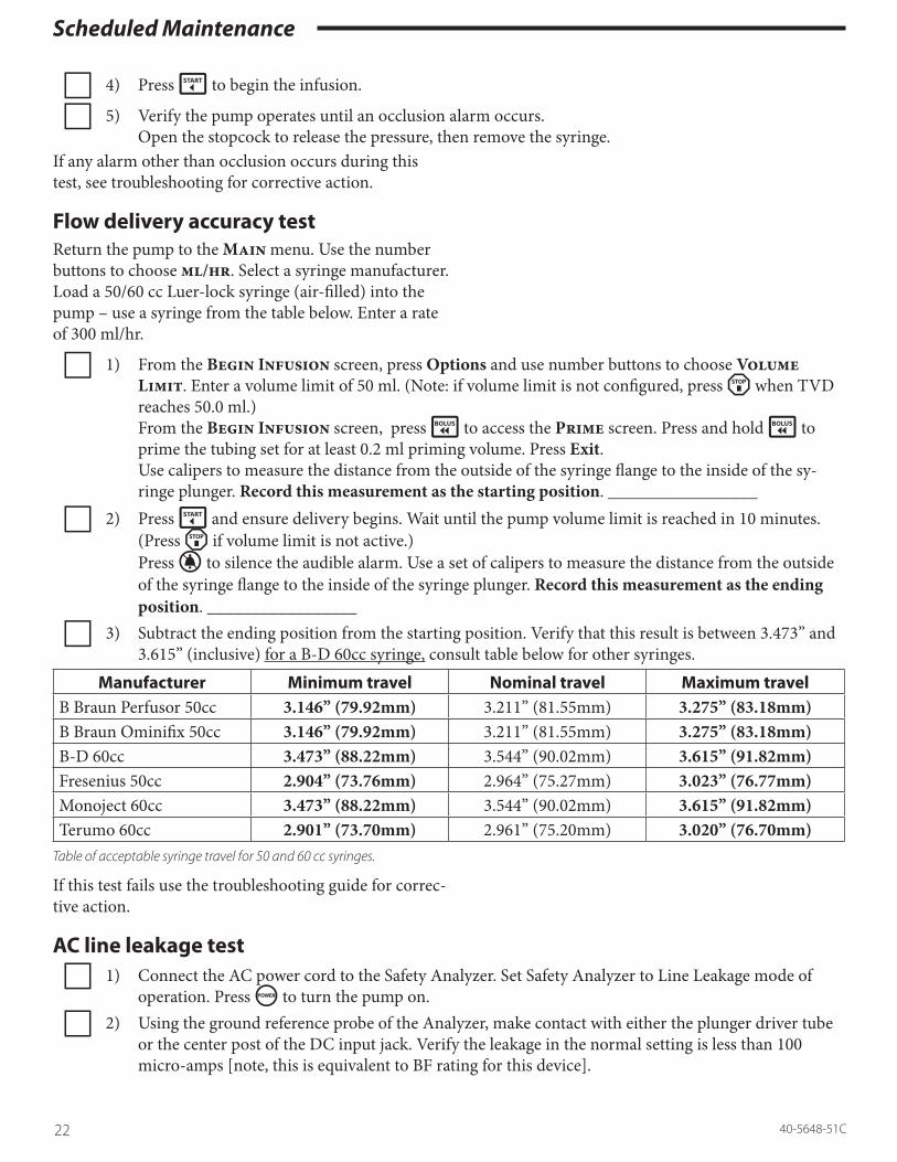
c 4) Press É to begin the infusion.
c 5) Verify the pump operates until an occlusion alarm occurs. Open the stopcock to release the pressure, then remove the syringe.
If any alarm other than occlusion occurs during this test, see troubleshooting for corrective action.
Flow delivery accuracy testReturn the pump to the Main menu. Use the number buttons to choose ml/hr. Select a syringe manufacturer. Load a 50/60 cc Luer-lock syringe (air-filled) into the pump – use a syringe from the table below. Enter a rate of 300 ml/hr.
c 1) From the Begin Infusion screen, press Options and use number buttons to choose Volume Limit. Enter a volume limit of 50 ml. (Note: if volume limit is not configured, press á when TVD reaches 50.0 ml.) From the Begin Infusion screen, press è to access the Prime screen. Press and hold è to prime the tubing set for at least 0.2 ml priming volume. Press Exit. Use calipers to measure the distance from the outside of the syringe flange to the inside of the sy-ringe plunger. Record this measurement as the starting position. _________________
c 2) Press É and ensure delivery begins. Wait until the pump volume limit is reached in 10 minutes. (Press á if volume limit is not active.) Press í to silence the audible alarm. Use a set of calipers to measure the distance from the outside of the syringe flange to the inside of the syringe plunger. Record this measurement as the ending position. _________________
c 3) Subtract the ending position from the starting position. Verify that this result is between 3.473” and 3.615” (inclusive) for a B-D 60cc syringe, consult table below for other syringes.
Manufacturer Minimum travel Nominal travel Maximum travelB Braun Perfusor 50cc 3.146” (79.92mm) 3.211” (81.55mm) 3.275” (83.18mm)B Braun Ominifix 50cc 3.146” (79.92mm) 3.211” (81.55mm) 3.275” (83.18mm)B-D 60cc 3.473” (88.22mm) 3.544” (90.02mm) 3.615” (91.82mm)Fresenius 50cc 2.904” (73.76mm) 2.964” (75.27mm) 3.023” (76.77mm)Monoject 60cc 3.473” (88.22mm) 3.544” (90.02mm) 3.615” (91.82mm)Terumo 60cc 2.901” (73.70mm) 2.961” (75.20mm) 3.020” (76.70mm)
Tableofacceptablesyringetravelfor50and60ccsyringes.
If this test fails use the troubleshooting guide for correc-tive action.
AC line leakage testc 1) Connect the AC power cord to the Safety Analyzer. Set Safety Analyzer to Line Leakage mode of
operation. Press ë to turn the pump on.
c 2) Using the ground reference probe of the Analyzer, make contact with either the plunger driver tube or the center post of the DC input jack. Verify the leakage in the normal setting is less than 100 micro-amps [note, this is equivalent to BF rating for this device].

Scheduled Maintenance
2340-5648-51C
IfyouwishtoverifytheCFratingofthepump,thenfillabeakerwithnormal(0.9%)salinesolutionandloadthepumpwithasyringeandtubingfilledwithnormalsaline.Thesaline-filledtubingshouldbeincontactwiththesalineinthebeaker.PlacethegroundreferenceoftheleakagecurrentAnalyzerincontactwiththesalineinthebeakerandverifytheleakagecurrentinthenormalsettingislessthan10micro-amps.[ThisprocedureisspecifiedinIEC60601-2-24,clause19.]
Turn off pump and disconnect from safety analyzer.
WARNING: Safety Class II, Type CF Medical Equipment: The pump is listed as Safety Class II, Type CF equipment. Protection against electrical shock does not rely only upon basic insulation, but instead relies on double or reinforced insulation. As such, this equipment does not utilize a third wire ground (earth ground).Therefore, when doing line leakage test it is not nec-essary to measure leakage in both the open ground and closed ground setting. Nor is it necessary to perform a ground resistance test.
AC line leakage test - Medfusion® 3500BC
c 1) Connect the AC power cord to the Safety Analyzer. Set Safety Analyzer to Line Leakage mode of operation. Press ë to turn the pump on.
c 2) Enclosure Leakage - Using the ground reference probe of the Analyzer, make contact with the center post of the DC input jack. Verify the leakage in the normal setting is less than 100 micro-amps [note, this is equivalent to BF rating for this device].
c 3) Earth Leakage - Use the Safety Analyzer, to measure the leakage current flowing through the earth conductor of the AC power cord.
Verify the leakage in the normal setting is less than 100 micro-amps [note, this is equivalent to BF rating for this device].
IfyouwishtoverifytheCFratingofthepump,thenfillabeakerwithnormal(0.9%)salinesolutionandloadthepumpwithasyringeandtubingfilledwithnormalsaline.Thesaline-filledtubingshouldbeincontactwiththesalineinthebeaker.PlacethegroundreferenceoftheleakagecurrentAnalyzerincontactwiththesalineinthebeakerandverifytheleakagecurrentinboththenormalandreversedsettingsislessthan10micro-amps.[ThisprocedureisspecifiedinIEC60601-2-24,clause19.]
Turn off pump and disconnect from Safety Analyzer.
WARNING: Safety Class II with functional earth, Type CF Medical Equipment: The pump is listed as Safety Class II with functional earth, Type CF equip-ment. Protection against electrical shock does not rely only upon basic insulation, but instead relies on double or reinforced insulation. As such, this equip-ment utilizes a third wire ground (earth ground) lead of the power cord as earth return for electro-magnetic energy and does not serve as a safety func-tion.Therefore it is neither possible nor necessary to per-form a ground resistance test.
Scheduled Maintenance
24 40-5648-51C
Battery maintenanceThis chapter discusses battery maintenance as recom-mended to ensure good battery performance.
1. The battery pack contains six 2100 mAH Nickel Hydride (NiMH) cells (older pumps may have Nickel Cadmium [NiCad] batteries) with a smart gauge for monitoring battery charge information.
Notes: • The gauge is built into the battery pack, and the pump reads the battery capacity from the gauge on the pack. • The battery pack has a shelf life of 4 months, after which it will require recharging. Once installed into a pump, the shelf life is 2 months, after which it will require recharging.
2. There are two measured battery parameters that must be reviewed to maintain good battery per-formance and accuracy of the battery gauge. From the Main menu, use the number buttons to choose Biomed; use the number button to choose Diagnostics; use the number buttons to choose Monitor Battery Status option.
a) LMD (Last Measured Discharge) − This the learned capacity of the battery by the gauge fol-lowing a calibration cycle. It is recommended the battery be replaced when this value is < 1600 mA-hours.
b) CPI (Capacity Inaccurate) − This is the number of shallow discharge cycles since the last calibra-tion. It is recommended that you recalibrate the battery when CPI is > 80 hex (i.e. >128 decimal). Refer to the battery calibration section below.
Shallow discharge (CPI) recordThe battery gauge records the number of shallow discharges. A shallow discharge happens whenever the battery is partially discharged and then returned to AC power. The number of the shallow discharges ap-pears on page two of the Monitor Battery Status menu in the Biomed > Diagnostics menu.
• This displays CPI as 0×DD, where 0×DD is a hexadecimal number representing the number of shallow discharges cycles.
• The value is reset to zero each time the battery is calibrated. It increments to a maximum count of 0×FF hex (255 decimal).
During the annual periodic maintenance if the num-ber of shallow discharges, CPI, is 0×80 hex or higher [e.g. 0×90, 0×A5, 0×BB, etc.], then the battery should be re-calibrated.
Battery calibration procedure The battery calibration procedure ensures the battery calibrates (or “re-learns”) the battery capacity. It does this by measuring the actual charge & discharge rates to determine the true capacity of the battery. With this correct information, the pump calculates “percentage of battery charge” and determines “low battery alarm”.
1. Connect the pump to AC power.2. Turn the pump on and select Biomed > Diag-
nostics > Monitor Battery Status. 3. After the Charge Level gauge reaches 99 to 100%,
wait at least 1 more hour, then remove AC power. 4. Using one of the methods listed here, fully drain
the battery pack, until the pump sounds the Bat-tery Depleted alarm (not the Low Battery alarm). You can interrupt the discharge test by turning the pump off and continue discharge at a later time – as long as you do not plug the pump into AC power during the discharge cycle.
a) The battery can be discharged by operating the pump on battery power and infusing at 5 ml/hr using a 60cc syringe. This takes approximately 10 hours from a full charge.
b) A quicker method is holding open the clutch lever with an a clamp or vise grips to prevent the plunger flipper and clutch from closing. Then use Biomed > Diagnostics > Motor Drive Test, and set motor step period to 2 msec, and press É. This should deplete the battery within approximately 3 hours .
c) A third method is to disconnect AC power, turn the pump on, and run Biomed > Diagnostics > Monitor Battery Status. This discharges the battery at about 130 ma, and takes approxi-mately 13 hours from full charge.
5. Once the Battery Depleted alarm sounds, turn the pump off and plug into AC. This begins recharging the battery. [Do not unplug AC power until charging is complete.]
If left in “Depleted” alarm condition, the pump will draw power from the battery until its voltage drops

Scheduled Maintenance
2540-5648-51C
to a level which disconnects the battery gauge. The pump then loses all its calibration information. From the time the Battery Depleted alarm occurs, the pump has approximately 5 minutes of operation on battery before the “fully-depleted dis-connect” condition occurs. At this point, the audible alarm continues running from the super-capacitor on the main board.
6. After several minutes of recharging the gauge will show the learned capacity of the battery.
7. Turn the pump on and select Biomed > Diag-nostics > Monitor Battery Status.
8. Verify LMD (last measured discharge) value is greater than 1600 ma-hours.
9. Press More and verify CPI is 0×00 or 0×01.10. Turn the pump off and continue to charge pump
until battery charge is complete (approximately 10 hours).
11. Turn on pump and select Biomed > Diagnos-tics > Monitor Battery Status.
12. Verify the LMD is greater than 1600 mA-hours. At 1600 mA-hours battery, the pump’s battery life is approximately 7-8 hours. It is recommended that the battery be replaced if its capacity is less than 1600 mA-hours.
Requirements for battery pack replacementThe battery must be replaced only by a trained Bio-medical or service technician. Always dispose of depleted or defective batteries in compliance with all applicable regulations or you may return the battery pack to Smiths Medical for recycling.
WARNING: Battery Replacement: Observe ESD handling precautions when replacing the battery. Replace battery only with same Smiths Medical part/model number.
Recycle batteries in compliance with applicable local regulations.
Collect SeparatelyThis product contains electrical and electronic com-ponents (including batteries) that may contain materi-als, which if disposed of with general waste, could be damaging to the environment.
In accordance with Directive 2002/96/EC Waste Electrical and Electronic Equipment, residents of the European Union must follow specific disposal or recy-cling instructions for this product. Contact your local distributor, or visit the following web site for specific instructions:
http://www.smiths-medical.com/recycle/index.html
Non-European Union residents must dispose of or re-cycle this product (including batteries) in accordance with the local laws or regulations that apply.
WARNING: Collect Separately. There are potential health hazards associated with improper disposal of batteries, electronics, and contaminated (used) infusion sets and syringes. Dispose of used batteries, infusion sets, syringes, and other used accessories, or a pump that has reached the end of its useful life, in an environmentally safe manner, and according to any regulations that may apply.

Scheduled Maintenance
26 40-5648-51C

Theory of Operation
2740-5648-51C
Section 2: Theory of Operation of the manual con-tains definitions and descriptions of standard opera-tion of the Medfusion® 3000 Series pumps.
Overview of operationThe Medfusion® 3000 Series pump design allows the precise control of the infusion rates over a wide range of syringe sizes and manufacturers as specified in the Operation Manual.
Controlling motor functionsA stepper motor driving the plunger driver controls the infusion rate. The motor receives electrical pulses from microcontroller with pulse frequency deter-mined from the programmed flow rate.
• Forty-eight motor pulses turn the motor one full revolution.
• Five hundred and sixty full motor revolutions move the plunger driver one inch.
• Therefore, 26,880 motor steps move the plunger driver 1 inch (or 0.000037 inches per motor step) − providing very good flow continuity and precise delivery.
Infusion control & safety functionsTwo sensors are used to verify that the infusion pro-ceeds at the programmed rate. Specifically, the micro-controller uses:
a) the motor rotation sensor to verify proper motor speed;
b) the position sensor to verify proper syringe plunger driver motion over time.
If the microcontroller determines either motor or sy-ringe plunger driver is running at a speed not equiva-lent to the programmed flow rate, then the infusion stops and a system fault alarm warns the user.
Four additional sensors verify the syringe parameters:
a) The plunger sensor, in the head of the plunger driver, detects proper engagement of syringe plunger with syringe plunger driver.
b) The flange clip detects the proper position of the syringe flange.
c) The syringe barrel clamp detects both syringe pres-
ence and syringe size. d) A force sensor in the plunger driver head detects
and reports the amount of force exerted on syringe plunger head. A large amount of force indicates an occlusion in the patient line to the microcon-troller.
A Watchdog device checks for microcontroller mal-function including timebase errors, and can shutdown the motor and generate an alarm independent of the microcontroller operation. An internal power source (i.e., 1 Farad super-capacitor) allows the pump to alarm should failure occur in the pump’s power sys-tem or internal battery.

Theory of Operation
28 40-5648-51C
Pump design description Listed in this chapter are descriptions of each functional block and its role in pump operation and system safety.
Logic core of Medfusion® 3000 Series pumpsThe block diagram below shows interrelation between the different assemblies of the Medfusion® 3000 Series pump.
Graphical Display Board240x64
Keypad & Indicator Lights
Spea
ker
IR Serial CommLink
AC Power Input& Power Supply
DC Power InputJack
RechargeableBattery Pack &Battery Gage Interconnect
Board
Main System Board(Logic Core)
Watch-Dog
Buzzer
SensorMotor Rotation
StepperMotor
Syringe SizeSensor
SensorSyringe Ear Loaded
SensorPlunger Travel
Loaded SensorSyringe Plunger
& PreAmp BoardForce Transducer
BlockDiagramforMedfusion®3000SeriesInfusionPump
Main circuit boardMain microprocessorThe main circuit board has one main microprocessor, 68HC11, with responsibilities for the following tasks:
a) Controlling the graphical display of information.b) Responding to the keypad and controlling visual
indicators on the keypad.c) Controlling the primary speaker.d) Controlling the stepper motor which drives the
syringe plunger.e) Monitoring syringe sensors: syringe size, syringe
flange (ear) loaded, syringe plunger loaded, syringe plunger position, and syringe plunger force.
f) Communicating with the smart battery gauge.g) Controlling the external serial communication.

Theory of Operation
2940-5648-51C
Watchdog circuitA watchdog circuit has a separate power supply and separate (PIC) microcontroller/clock which monitors the main microprocessor. The watchdog circuit detects microprocessor timing failures and initiates a watch-dog alarm through a dedicated “back-up” audible alarm which is separate from the primary speaker.
If a watchdog or “System Failure” alarm is gener-ated, then watchdog circuit turns on the red alarm indicator and backup audible alarm, and turns off the motor current.
DC power converterThe DC Power Converter generates required system DC voltages from the available power source coming from the interconnect board. This power source can be either battery power, or AC power, or external DC power. The main microprocessor monitors these volt-ages and will detect failures in any system voltages.
Real time clockA separate Real Time clock source provides the micro-processor with date and time information. The date and time are used for time-stamping records in alarm history and infusion history, and for determining the next recommended Periodic Maintenance date.
Graphical display circuit board (LCD)A 240 × 64-pixel liquid crystal display provides the pri-mary visual interface for pump operation.
• An always on LED driven back light in the LCD enhances viewing in low light areas.
KeypadThe keypad is a multi-layer polyester laminate provid-ing buttons for controlling the pump, and indicator lights for identification of pump status.
Plunger (driver) travel sensorThe plunger travel sensor is a precision potentiometer producing a change in voltage (resistance) with the motion of the syringe plunger driver. This allows the microprocessor to determine:
• plunger speed• near end of plunger travel (i.e,. near empty alarm)• end of plunger travel (i.e., empty alarm)
The microprocessor uses sensor output to verify plunger travel against set flow delivery rate. The sensor output is not used for rate correction.
Motor rotation sensorThe motor rotation sensor is an optical reflective sensor which senses 4 pulses per motor rotation. The micro-processor measures the frequency of this signal to:
• Verify rotation speed against the set flow delivery rate. It is not used for speed correction.
Stepper motorThe stepper motor drives the syringe plunger driver.
• Each motor step is controlled by the microproces-sor using an open loop control method.
Syringe flange loaded sensorThe syringe flange sensor requires the flange be in-stalled in the flange locating device on the pump.
• Reports a logic state to the microprocessor to indi-cate proper syringe flange loading.
• Uses self test signal to verify the sensor is not in an electrically “stuck” state.
Syringe size sensorThe syringe size sensor is a precision potentiometer which produces a voltage (resistance) proportional to the outside barrel diameter of the syringe loaded into the pump. This allows the microprocessor to measure:
• Voltage proportional to syringe barrel outside diameter to determine the syringe size (e.g. 10cc, 20cc etc.) or syringe not loaded.
Interconnect printed circuit boardReceives and directs the power source, either internal 12VDC power supply, internal battery, or external DC power to the “Main” board.
a) Generates status signals to “Main” board indicat-ing source of power supplied.
b) Contains battery charger for charging the battery.c) Contains an infrared drivers for serial communi-
cation interface with the pump.d) Supplies the audio drive signal, originating from
the “Main” board, to power the speaker.

Theory of Operation
30 40-5648-51C
AC power input & power supply boardThis AC Power Input provides a receptacle for con-necting an IEC 320-type AC power cord to the inter-nal, universal input power supply. This Power Supply Board provides 12 VDC to operate the pump and charge the batteries.
DC power input jackThe DC Power Input Jack connects external DC power into the pump from external DC sources. This input is protected from over-voltage and reverse polarity.
• Always observe all cautions and warnings for con-necting DC power to this input.
SpeakerThe primary speaker serves as the primary audio source for generating alarms.
• The microprocessor senses speaker current to determine if speaker is operational.
Rechargeable battery pack & battery gaugeA rechargeable NiMH battery pack (NiCad battery pack on older model pumps) allows operation on bat-tery, which also serves to provide backup power with the loss of externally applied AC or DC power
A gauge residing on the battery pack maintains pres-ent battery capacity during charge and discharge conditions. The gauge monitors battery temperature and controls the battery charger in setting the charge rate. The pack contains a resettable fuse which limits the current flowing through the battery.
Plunger printed circuit boardThis plunger printed circuit board (PCB) provides connection and pre-amplification of sensors in the plunger driver to the main microprocessor board. The plunger PCB contains the force sensor amplifier and the plunger loaded sensors.
Plunger force sensorThe plunger force sensor is a full bridge strain gauge which generates a voltage proportional to the force ap-plied by the plunger driver to push the syringe plung-er. The allows the microprocessor to measure:
• Voltage proportional to force applied to the sy-
ringe plunger (i.e. occlusion detection).• Uses self test control line to verify force sensor and
circuitry are operating properly.
Plunger Loaded SensorsThe two plunger loaded sensors are located on the plunger PCB, and sense the state of each “flipper” on the plunger driver.
• Reports a logic state to the microprocessor to indi-cate proper syringe plunger loading.
• Uses self test signal to verify the sensor is not in an electrically “stuck” state.

Theory of Operation
3140-5648-51C
Main Board – Schematic LevelThe Main printed circuit board design has the following sub-circuits:
• Logic kernel • Motor speed detection• Power control • Syringe sensing• DC-DC Converter • Plunger position sensor• Front panel interface • Force sensing• Graphic display • Speaker drive
interface• Motor drive
Each of the sub-circuit descriptions is presented in the order of the schematic pages of the Medfusion® 3000 Series “Main Printed Circuit Board”. The signal names marked with the asterisk symbol on the schematic indi-cate that those signals are “active-low”.
In the block diagrams for each section, the arrows indicate data flow direction referenced to the main microprocessor. In some cases, the arrows will identify a device other than the microprocessor to which the sig-nal directly interfaces, (e.g., analog to digital converter).
Logic Kernel DescriptionThe Medfusion® 3000 Series Logic Kernel Main PC flowchart is below. It shows linkage between the 68HC11K1 microprocessor and the main components of the system:
68HC11K1Main Processor
32Kb Serial EEPROM Infrared
X-Ceiver
10 Bit A/DConverter
8 Bit D/AConverter
24 1/O BitPort 2
Expansion(82C55)
24 1/O BitPort 1
Expansion(82C55)
32Kb StaticRAM
4 Mb FlashMemory
Time of DayIC
T×D, R×DPA4, SPI PH6, SPI
I/O $1200I/O $1000
PG1, SPI
PG6, SPI
$0 - $7FFF
$8000 - $FFFF
FlowchartofLogicKernelforMedfusion®3000Seriesinfusionpump
68HC11K4 Main Microprocessor Interface, U19 The main microprocessor’s direct signal interfaces are described in clockwise order taken from the Medfu-

Theory of Operation
32 40-5648-51C
sion® 3000 Series Main PC Schematic of the micro-processor. The following table summarizes some of the microprocessor input / output signals.
Signal name Processor port Descriptionir_xmt_data PD1/TxD The ir_xmt_data is used for transmitting asynchronous serial
data.ir_rcv_data PD0/RxD The ir_rcv_data is used for receiving asynchronous serial data.speaker_frequency PH0/PW1 Sets the audio frequency of the main speaker. Generated as a fixed
50% duty cycle (square wave) with a variable frequency.speaker_volume PH1/PW2 Fixed frequency variable pulse widths signal that the speaker- driv-
er hardware converts into a DC voltage for volume control.mtrpha_iref PH2/PW3 Pulse-width modulated output transformed by hardware into a DC
level representing motor current for coil “A” of the motor.mtrphb_iref PH3/PW4 Pulse-width modulated output transformed by hardware into a DC
level representing motor current for coil “B” of the motor.adc_cs* PG6 Chip select signal for SPI communication to the 10-bit analog to
digital converter. This signal is active low.dac_cs* PG1 Chip select signal for SPI communication to the 8-bit digital to ana-
log converter. This signal is active low.reset_pio PG0 Allows the main processor to independently reset the two 24 bit I/O
expansion devices. The reset is active high.power_strobe PD5 Controls the power state of the system. Must be an AC signal to
maintain the power on state. A stuck state of either logic high or low, is one of the conditions for enabling the power off state.
plunger_detect1 PA6/OC2 Logic sense signal for detecting the respective plunger flipper state. A logic high indicates a syringe is loaded.
plunger_detect2 PA5/OC3 Logic sense signal for detecting the respective plunger flipper state. A logic high indicates a syringe is loaded.
acu_pwr_strb_on PA4/OC4 This feedback signal to check that ACU is still controlling power to the system. When power is on, acu_pwr_strb_on measures > 4.0 volts nominally.
async_battery_data
PA3/IC4/OC5 The single wire asynchronous data communication between the main processor and the battery gauge located on the battery pack. This port pin is bi-directional, both input & output.
io_cs* CSIO Chip select for the two 24 bit I/O expansion devices. This signal is active low.
ram_cs* CSGP1 Chip select for the main processor’s external random access memo-ry (RAM). This signal is active low.
eeprom1_cs* PH6 Chip select for SPI communication to the serial E2 PROM #1. This signal is active low.
flash_cs* Chip select for access to the main processor’s programmed memory (Flash). This signal is active low.

Theory of Operation
3340-5648-51C
Signal name Processor port Descriptionwrite*, e_clock, xaddr[15:18], addr[0:14], data[0:7]
R/w*, E, XAD-DR15 - XAD-
DR18, ADDR0 - ADDR14, and DATA0
- DATA7
The main processor control bus signals that route to the memory and I/O expansion devices. The address line addr15 is not used.
spi_clock, spi_mosi, and spi_miso
SCK, MOSI, MISO
These signals are used for SPI bus communication to the Serial EEPROM, Time of Day Clock, Analog to Digital Converter, and the Digital to Analog Converter.
atod_ref_bfrd AN0 Input for main processor to verify the reference voltage used by the 10-bit analog to digital converter and system reference. The nomi-nal measured reference voltage is 2.048 volts.
supercap_detect AN1 Analog signal proportional to the Super Capacitor voltage. When fully charged, supercap_detect measures 2.5 volts nominally. The main processor read supercap_detect to verify the Super capaci-tor is present.
pwr_strb_on AN2 Feedback signal is to check the proper operation of the power con-trol circuit. When power is on, pwr_strb_on measures > 4.0 volts nominally.
motor_sply_meas AN3 Signal is proportional to the motor supply voltage. The nominal DC voltage for this signal is 1.09 volts, exactly a sixteenth of the motor supply voltage.
analog_sply_meas AN4 Signal is proportional to the analog supply voltage. The nominal DC voltage for this signal would be 2.5 volts nominally, exactly one half of the analog supply voltage.
force_psv_adj AN5 Feedback signal proportional to the offset voltage used on the force sensor pre-amplifier. Its voltage range dependent upon the offset voltage setting (a calibration value).
speaker_detect AN6 Feedback signal proportional to the current through the main speaker. Its level depends on the volume setting for the speaker.
vpos_sply_meas AN7 Signal is proportional to the positive supply voltage. The nominal DC voltage for this signal is 2.397 volts, exactly one fourth of the vpos_sply supply voltage.
mtr_timer PA7/OC1 Time base used by the main processor to control motor step timing and an input to the highest, maskable interrupt source.
motion_detect PA2/IC1 Signal is the encoded output from the optical motor rotation detec-tor.
buzzer_detect PA1/IC2 Feedback signal from the audio buzzer detection circuit. This signal is logic high whenever the audio buzzer is active.
tod_intrpt PA0/IC3 An independent time base provided by the time of day clock. This is a 1 Hz frequency signal.
MOD_A, MOD_B
These inputs configure special processor operational modes.

Theory of Operation
34 40-5648-51C
Signal name Processor port Descriptionreset* Reset Provided from the system-reset circuit located in the Power Control
Logic section of the Main PCB.VRH 4.096V A/D reference.
AVDD, AVSS, and VRL
The main processor’s analog to digital conversion supply and refer-ence pins.
Flash memory, U22Flash program memory is 512 K × 8. It is addressed as 16 pages of 32 K × 8 each.
Flash memory can be reprogrammed within the system.
Software upgrade method for programming flash memoryThe re-programmable feature of Flash Memory provides for software upgrades. The pump is placed in a special Biomed mode which allows reprogramming of the soft-ware through the infrared serial port.
Static random access memory, U17Static RAM is 32 K × 8 bit.
Serial EEPROM, U2 and U4The serial EEPROMs are used for storing manufactur-ing, calibration, configuration, libraries, the history event log, the PharmGuard® Safety Data, and the service data requiring non-volatile random access.
Medfusion® 3000 series pumps may have two 8K x 8 bit EEPROMs, two 16K x 8 EEPROMs, or two 32K x 8 EEPROMs.
Time of day, U8The time of day, including calendar, is maintained by the RS5C316B which is continually powered as long as AC, external DC voltage, or internal battery is present, or the super capacitor is charged.
Infrared transceiverAn IR transceiver, located on the Interconnect board, provides an electrically isolated asynchronous serial communication link between the pump and an external system. The infrared link is intended for short distances of less than a few inches.

Theory of Operation
3540-5648-51C
Analog to digital converter, U13A four channel, unipolar, 10-bit converter obtains high resolution analog measurements.
The high resolution measurements in ascending chan-nel order are:
• pressure sensing amplifier• plunger force sensing amplifier• syringe size sensing amplifier• plunger travel sensor. The converter uses precision 4.096-volt reference equating to a bit resolution of 4 millivolts. The con-verter interfaces to the Serial Peripheral Interface of the 68HC11.
Digital to analog converter, U20A dual channel 8 bit digital-to-analog converter:
• Generates the contrast voltage for the Liquid Crys-tal display,
• Generates an offset to the force sensing amplifier. Uses precision 4.096-volt reference equating to a nominal bit resolution of 16 millivolts. Channel A is the source for the force amplifier, and channel B is the contrast voltage reference.

Theory of Operation
36 40-5648-51C
I/O port expansion, U3, U33There are two 82C55 input/output port devices provid-ing the additional input/output requirements for the microprocessor. They are accessed through the I/O chip selects port1_cs* and port2_cs*.
Expansion port # 1 (port1_cs)Signal name Port location Description
eeprom2_cs* PB7 A logic low enables accessing the 2nd serial EEPROM.pet_watchdog PB6 A logic signal used as a handshake for indicating valid operational
status to the auxiliary controller.supercap_test PB5 A logic high enables testing the super-capacitor, (i.e., backup power
source).tod_cs PB4 A logic high enables accessing the time of day IC.tod_wr_enbl* PB3 A logic low enables writing data to the time of day IC.speaker_envelope3 PB2 A logic high selects the audio envelope time constant of 35 millisec-
onds. Refer to the Main Speaker Drive description section.speaker_envelope2 PB1 A logic high selects the audio envelope time constant of 11 millisec-
onds. Refer to the Main Speaker Drive description section.speaker_envelope1 PB0 A logic high selects the audio envelope time constant of 2.5 milli-
seconds. Refer to the Main Speaker Drive description section.warning_led_on* PC7 A logic low turns the “Caution” LED indicator on.infusing_ledl_on* PC6 A logic low turns the left most (when viewing the keypad) “Infus-
ing” LED indicator on.infusing_ledm_on* PC5 A logic low turns the middle “Infusing” LED indicator on.infusing_ledr_on* PC4 A logic low turns the right most “Infusing” LED indicator on.pcell_led_on* PC3 A logic low turns the “Pressure Cell” LED indicator on.battery_led_on PC2 A logic high turns the “Battery” LED indicator on.caution_led_on* PC1 A logic low turns the “Caution” LED indicator on.lockout_led_on* PC0 A logic low turns the “Tamper Feature Active” LED indicator on.keypad_in_col(0-5) PA0-PA5 Senses 1 of 6 columns of the keypad matrix. When the sense value
is logic low, the indication is the corresponding button for the col-umn is being pressed.
pwr_sw_mcu PA6 Sense signal for the power switch. The signal is at a logic high when the power switch is being pressed.
mtr_current_de-tect*
PA7 Sense signal from the motor current detector circuit. If the motor is energized with sufficient current in any coil, this signal is at logic low.

Theory of Operation
3740-5648-51C
Expansion port # 2 (port2_cs)Signal name Port Location Description
set_in_snsr_enbl* PB6 Set to logic low to enable the “set in” detector to sense the pressure cell being installed.
syringe_ear_snsr_enbl
PB5 Set to logic high to enable the “syringe” detector to sense the syringe flange (ears) being installed.
plunger_snsrs_enbl PB4 Set to logic high to enable the “plunger” detectors to sense the plunger flippers being properly engaged.
motion_snsr_enbl PB3 Set to logic high to enable the motion sensor monitoring the motor speed.
force_snsr_test* PB2 Set to logic low to activate the force sensor test circuit. This signal causes the sensor to generate a known offset if the sensor is operat-ing properly.
pressure_snsr_test* PB1 Set to logic low to activate the pressure sensor test circuit. This signal causes the sensor to generate a known offset if the sensor is operating properly.
lcd_reset* PB0 Allows the main processor to reset the LCD display independently of other system devices. The reset signal is active low.
mtr_phb_dir PC7 Controls the direction (phase) of motor current in coil “B” of the stepper motor.
mtr_phb_enbl* PC6 Set to logic low to enable motor current in coil “B”.mtr_pha_dir PC5 Controls the direction (phase) of motor current in coil “A” of the
stepper motor.mtr_pha_enbl* PC4 Set to logic low to enable motor current in coil “A”.keypad_sel_row3* PC3 Control signal to select row 4 of the four-row keypad matrix. To
select the row requires a logic low and only one row at a time.keypad_sel_row2* PC2 Control signal to select row 3 of the four-row keypad matrix. To
select the row requires a logic low and only one row at a time.keypad_sel_row1* PC1 Control signal to select row 2 of the four-row keypad matrix. To
select the row requires a logic low and only one row at a time.keypad_sel_row0* PC0 Control signal to select row 1 of the four-row keypad matrix. To
select the row requires a logic low and only one row at a time.buzzer_armed PA0 A logic high indicates the backup audio buzzer is ready to alarm
should the “watchdog” alarm state become true. A series resistor is provided to prevent latching.
watchdog_alarm PA1 A logic high indicates the “watchdog” alarm state is true.extrnl_pwr_detect PA2 A logic high indicates an external power source is connected to the
pump. A series resistor is provided to prevent latching.ac_pwr_detect PA3 A logic high indicates AC line power is connected to the pump. A
series resistor is provided to prevent latching.syringe_ear_detect PA5 A logic high indicates the syringe flange (ears) are installed properly
in the pump and syringe_ear_snsr_enbl is active.set_in_detect PA6 A logic high indicates the pressure cell is installed and set_in_
snsr_enbl is active.vlow_battery PA7 A logic high indicates the battery voltage has fallen below a fixed
voltage level, independent of the battery being charged.

Theory of Operation
38 40-5648-51C
Power control descriptionThe power control logic provides two functions, power management, and triggers alarms when the main micro-processor fails. Refer to the Power Control Logic section of the Main PC Schematic for details.
Auxiliary Controller
Power Control
WatchdogAlarm Circuit
Super Capacitor
AudioBuzzer
ProcessorReset Circuit
BuzzerDetector
5 Volt AlwaysOn Supply
Mains Supply
Battery
External DC
Logic Supply
Test Supercap
Reset to Processor
Monitor Super CapacitorProcessor A/D Channel AN1
Main Power On
Watchdog Alarm
FlowchartofPowerControlDescription.
Always on supply, U7 A 5-volt linear regulator provides power to the time of day clock and auxiliary controller, while maintaining a charge on the super capacitor.
• This supply is always active provided a power source is present be it the regulated mains AC power, bat-tery, or external DC.
Backup super capacitor, C11This device provides backup power to the audio buzzer in the loss of the primary power source, a 1 Farad Super Capacitor is part of the power control design.
• The super capacitor voltage supercap_detect, is monitored through the microprocessor’s A/D converter channel by the microprocessor asserting supercap_test when the pump is turned on.
Backup audio buzzer, XD1The audio buzzer provides a means to generate a backup audible alarm during:
• instrument power loss (while the instrument was on)• malfunction of the main microprocessor• or failure of the primary speaker.

Theory of Operation
3940-5648-51C
The audio buzzer is enabled when the pump is turned on, and when the watchdog_alarm signal activates. The watchdog_alarm signal (from the auxiliary controller) activates anytime there is a malfunction of the main microprocessor. The main microprocessor can activate this buzzer indirectly by not providing the pet_watchdog strobe to the auxiliary controller which causes a watchdog alarm.
• During power-up, the buzzer is tested by the watchdog alarm state being active, and the buzzer response verified through the buzzer_detect signal.
System reset, U43On startup, the microprocessor comes out of reset when the logic supply exceeds 4.6 volts plus the built-in delay of the reset IC.
Power management, U39An embedded Auxiliary controller oversees the power control management, and serves as the main micro-processor watchdog. The behavior of the power man-agement system depends on pump states:
• Power Off• Power On• Watchdog Alarm• and a Battery Disconnect.
Power OFF stateYou must press, hold, and release the power switch to turn OFF the power. In normal operation, both the auxiliary controller and the main microprocessor control power-off.
Power ON stateTo enter the power on state the power_enbl signal is initially set active by the auxiliary controller. This requires the auxiliary controller provide an AC strobe to the power_enbl circuit. This power_enbl signal also arms the backup audio buzzer. The power_enbl signal is verified by the main microprocessor monitor-ing the buzzer_armed signal.
WatchdogDuring a watchdog alarm, the auxiliary controller has sole control of power-off.

Theory of Operation
40 40-5648-51C
DC to DC converterThe circuits for the DC-DC Converter provide all regu-lated voltages required by the hardware sub-circuits.
• A switched DC source, (battery, regulated mains supply, or external DC) powers the converter section under the control of the Power Control circuitry.
• The converter design provides stable supply opera-tion from an unregulated DC source, simplifying the requirements for the switched sources.
• Refer to the DC-DC Converter section of the Main PCB schematic for details.
SwitchedDC Source
Logic Supply5 volt
Buck / BoostConverter
Main Supply17 volt
Boost Converter
Positive Supply+ 10 volts
Negative Supply– 10 volts Inverter
LCD ContrastSupply
LCD BacklightControl
Analog Supply5 volts Linear
FlowchartofDC&DCConverterOperation
Logic supply, U12The Logic Supply current-mode switching regulator provides a regulated output voltage of 5 volts (±5%) for the system logic.
Motor supply, U34The Motor Supply is a current-mode switching regula-tor provides a regulated output voltage of 17 volts for the motor current regulators.
Analog supply, U21The Analog Supply is provided specifically for low noise signal processing circuits. Being a linear supply, inher-ent noise rejection removes source input switching noise from it’s regulated output.

Theory of Operation
4140-5648-51C
Positive & negative supply, U36The negative supply is a charge pump DC-DC con-verter doubles the input voltage, then inverts the doubled voltage.
• Provides the contrast voltage to the graphic LCD display. The low current load for the contrast volt-age allows use of an operation amplifier controlled by the D/A converter through the SPI bus.
• Provides negative supply for the amplifiers used in force and pressure sensing.
• The charge pump doubles the “Logic Supply” volt-age to achieve a 10V nominal positive supply volt-age. This supply is used for analog circuits needing a supply voltage higher than the “Analog Supply”.
LCD backlight supply, U1A constant current regulator controls the primary LED back light for the LCD display. On the Medfu-sion® 3500 pump, the secondary LED for the backlight is controlled by Q45.

Theory of Operation
42 40-5648-51C
Front panel interface descriptionThe keypad interface has two circuits:
• the interface to the LED’s • the interface to the keypad switch matrix, and power
switch.
LED(s) DriveCircuits
LCD Input DataControl Circuits
Front Panel(Keypad)
Enable
Row Scan
Column Select
I/O Exp #2,PC0-PC7
I/O Exp #1,PA0-PA5
I/O Exp #2,PC0-PC3
FlowChartofFrontPanelFunction
LED drive circuit, Q26, Q27, Q40, Q33 - Q37Each LED drive circuit has a logic controlled switch providing a pseudo-current source to the LED when activated.
• All LED’s except the “Warning”, “Battery Charge”, and “AC Power” LEDs, are controlled exclusively by the main microprocessor.
Keypad matrix interfaceA 4 row by 6 column scan matrix senses the front panel keys:
• A pressed button is read from column signals, key-pad_in_colx, through the 82C55 port expander #1. A button press is sensed as a logic low.
• The keypad row signals are output from port C of the 82C55 port expander #2.
Power switch interfaceThe power switch has a circuit separate from the keypad matrix because it is monitored by both the main micro-processor and the auxiliary controller.

Theory of Operation
4340-5648-51C
Graphic display interface descriptionThe graphic display interface circuits have the main microprocessor control signals, read write, the device select signal lcd_cs*, a data output latch, a data input buffer, and a device reset.
Data output to LCD, U32 / data input from LCD, U6The data from the LCD to the main microprocessor is buffered by U32 and U6.
LCD contrastThe contrast control is created from the 8-bit digital to analog converter buffered with a 2.5 gain amplifier to provide minus contrast voltage.
• The full scale range of 255 (FF hexadecimal) counts equals approximately minus 10 volts.
LCD backlightThe primary backlight for the LCD is an LED driven by a constant current source. This backlight is always on whenever the pump is on.
The secondary backlight is not present on Medfusion® 3010 and 3010a pumps. Its on-off state is controlled by the CPU. During normal conditions, it is off when the pump is powered via the internal battery.

Theory of Operation
44 40-5648-51C
Motor drive descriptionA two-phase bipolar stepper motor drives the syringe plunger. The motor control interface drives the stepper motor.
Coil “B”Motor Current
Control
Coil “A”Motor Current
Control
Motor
MotorCurrent
Detector
Motor CurrentPhase A/A*
Motor CurrentPhase B/B*
ø Direction
ø Count Reference
ø Enable*
ø Current Reference
Motor Current Detect
ø Direction
ø Enable
Flowchart of Motor Drive Description
The main microprocessor controls which motor wind-ing is active, designated as A or B, the direction of cur-rent in each winding, and the magnitude of the current.
Coil A & B PWM current referencesThe pulse-width modulated signals from the main microprocessor are low pass filtered to create an analog voltages for control of motor current in each coil.
Motor current regulators, U26, U35Two regulator ICS independently regulate the current for windings A and B.
• The watchdog_alarm signal activates the N-chan-nel mosfet to disable the motor current in both windings through the “BRAKE” pin of the regulator IC.
Motor current detector, U40The watchdog alarm function is tested at power-up by verifying the mtr_current_detect* signal is at a logic high when the watchdog alarm condition is active.
• Similarly, the mtr_current_detect* signal should be at a logic low when either motor winding has suf-ficient current and the watchdog alarm condition is not present.

Theory of Operation
4540-5648-51C
Sensors interface descriptionMotor speed detectionThe digital sense signal is created by using a reflective infrared optical sensor to sense a motor-coupled en-coder as the motor rotates. The microprocessor mea-sures the period of the signal created by the encoder.
Syringe sensing descriptionThe syringe sensing system senses the syringe bar-rel size, senses the plunger end cap is secured by the mechanical flippers, and the syringe flange (ears) are located in the pump’s syringe flange locating device.
• The circuit for sensing the plunger flippers is part of the plunger printed circuit function.
Syringe size sensingSyringe sensing is accomplished by using a potenti-ometer which changes its resistance with the barrel diameter. The potentiometer is excited with a preci-sion 4.096v voltage reference and the potentiometer’s output is monitored through channel 2 of the system A/D.
• The sensing system requires calibration to deter-mine offset and gain. Calibration values are stored in non-volatile (serial EEPROM) memory.
Syringe flange (ear) sensingSyringe flange (or ear) sensor is used to detect if the syringe flange is installed in the flange-holder on the side of the pump.
An infrared optical interrupter detects when the flange-locating device is in a valid position. A prop-erly loaded flange causes the optical path to become uninterrupted allowing a direct path from the infrared emitter to the detector.
• The emitter is enabled by the signal syringe_ear_snsr_enbl when set to logic low.
• The sensor output, syringe_ear_detect, pro-duces a high logic state when the flange is properly loaded.
• The state should be logic low anytime the syringe ear (flange) is not installed or syringe_ear_snsr_enbl is inactive.

Theory of Operation
46 40-5648-51C
Plunger position sensing descriptionSensing syringe plunger position is required for the detection of an incorrect plunger speed, detecting near end of plunger travel, and detecting end of plunger travel.
The travel sensing circuits perform excitation and signal processing of the travel sensor. The travel sensor uses a linear potentiometer which produces a change in resis-tance with the motion of the syringe plunger.
• The sensing system requires calibration to deter-mine offset and gain. Calibration values are stored in non-volatile (serial EEPROM) memory.
Speaker drive descriptionThe speaker sounds the warning and caution alarm tones for the pump. The interface circuit controls the frequency and amplitude of the signal driving the speaker, and provides feedback for verifying speaker function.
Speaker Amplitude +Envelope Control Circuit
A/D Channel 6
Amplitude Envelope ControlI/O Exp #1 PD0-PD2
Frequency, PW1
Volume, PW2
SpeakerAmpli�cation
Speaker TestCircuit
IllustrationofSpeakerDrive
Speaker control• Tone duration is controlled by the interval the am-
plitude level is applied.• The speaker_frequency signal is a fixed 50% duty
cycle (square wave) with a variable frequency to 1 kHz.
• The speaker_volume is a pulse-width modulated signal converted by hardware to an analog voltage which controls the speaker volume.
• The rise and fall times of the volume are controlled by input signals from: speaker_envelope_1, speaker_envelope2, and speaker_envelope_3.

Theory of Operation
4740-5648-51C
Speaker testThe return signal from the speaker detects whether current is flowing in the Speaker from analog condi-tioning circuitry. The half-wave rectifier circuit uses the negative half-cycle of the sense signal to invert and amplify it.
• The amplified output is demodulated by the analog switch which creates a peak and hold circuit.
• The speaker_detect output signal from the conditioning circuitry goes to the microprocessor’s analog input.
Plunger board – schematic levelThe plunger PCB provides pre-amplification of the force sensor output to the Main system PCB, and contains two photo-interrupters with supporting cir-cuitry, one for each plunger flipper.
The referenced schematic signals of the main board electronics are identified using names in Smallcaps.
Force preamplifier functionThe force sensing system provides a measurement of the force required in moving the syringe plunger. The interface to the force sensor has an excitation source, test signal, and pre-amplification.
• The Main printed circuit board provides a fixed 4.096-volt excitation to the force sensor.
• The Main printed circuit board trims this offset range using the signal force_preamp_osadj.
• The Main PCB provides additional gain to maxi-mize measurement resolution.
Force sensing interface descriptionThe force sensing element is a full bridge strain gage, and the plunger PCB pre-amplifies and filters the out-put of this bridge. The interface has: sensor excitation, electronic zero-offset adjustment, amplification and filtering, and a sensor test control signal
• force_snsr_exh provides a constant voltage excitation of 4.096 volts DC to the sensor.
• Auto-Zero Adjustment Circuit provides a voltage to zero the pre-amplifier, force_osv_adj, from the 8 bit system D/A converter.
• Sensor Post Filter Amplifier is a second order low-pass filter with a 3.68x gain.
• The signal force_snsr_test* when set active low causes Q2 to apply a resistance parallel to the force sensor’s bridge resulting in a positive shift of the sensor output.
• The sensing system requires calibration to de-termine zero adjustment, offset, and gain. Cali-bration values are stored in non-volatile (serial EEPROM) memory.

Theory of Operation
48 40-5648-51C
Plunger flipper sensor functionPlunger flipper sensing requires each sensor detect its respective flipper position. Each infrared optical interrupter provides a high logic state when the flipper is in a valid position determined by a loaded syringe plunger. The transmitters for both photo-interrupters are driven in series; however, the optical receivers are read in parallel.
• Output from each photo-interrupter is monitored individually so each sensor is independently checked.
• When a syringe plunger is correctly loaded, both plunger_snsr1_out and plunger_snsr2_out are at a logic high.
• The transistor Q1 allows the sensor output to be tested by turning the transmitter from both sen-sors on and off. This is controlled by the signal plunger_snsrs_enbl from the Main PCB.

Theory of Operation
4940-5648-51C
Interconnect board – schematic levelThe interconnect printed circuit design interfaces to an intelligent rechargeable Battery, the system speaker, the internal DC supply, connection for an external DC sup-ply and the main PCB.
To MAIN PCB
SpeakerDecoupling
InfraredSerial Data
Port
DC Power Supply
Smart Battery
AC PowerDetector
External PowerDetector
Smart Charger
External DC Jack+ Filtering
FlowchartofInterconnectBoardatSchematicLevel
Each sub-circuit description is presented in the order of the schematic pages of the Medfusion® 3000 Series “Interconnect Printed Circuit”.
AC power detection descriptionThe AC power detector uses a zener diode regulator to provide a constant voltage to the signal ac_pwr_de-tect anytime AC power is provided to the pump. The regulated voltage is required for logic detection of AC power and is used to regulate the current through the AC LED indicator and the battery charge LED indicator.
• For ac_pwr_detect to be active, requires the DC input voltage (from the AC power supply) exceed 10 volts.
The ac_pwr_detect signal is also used to generate the signal battery_swx_on* which controls a battery switch to turn ON using battery power when AC power and external DC power are removed.
• The other effect of battery_swx_on* is delaying the battery charger from starting until the internal DC power supply reaches 10 volts.
A transient voltage suppressor protects the detection circuitry on the reg_dc_intrnl.

Theory of Operation
50 40-5648-51C
External DC power conditioning / detection descriptionThe external DC power input section limits current through a resettable fuse, both common and differ-ential mode noise suppression and transient voltage protection. The resettable fuse limits current into the pump from an external DC source. Noise filtering is performed by input and output capacitors on the conditioning circuit together with a common mode choke.
The external power detector uses a zener diode to pro-vide a valid logic high level when external DC power is applied. The active voltage for extrnl_pwr_de-tect is nominally 5 volts. The threshold detector U3 provides immediate detection, through the signal battery_swx_on*, of the external DC source being removed.
• A battery switch toggles to internal battery if both AC and external DC power are removed.
• The threshold detector also prevents the battery charger from charging the internal battery until the external DC power exceeds 5 volts.
Infrared serial data port descriptionThe infrared serial port interfaces directly with the main microprocessor’s asynchronous serial commu-nication pins. The infrared port supports short trans-mission distances of approximately 3” or less and a maximum baud rate of 9600.
The Infrared Receiver signal from U1 is conditioned by the comparator circuit of U4 to generate a valid logic state to the microprocessor.
The Infrared Transmitter signal ir_xmt_data is at a logic high during its inactive state. A logic low on ir_xmt_data enables the transmitting IR diode through the transistor Q3.

Theory of Operation
5140-5648-51C
Battery management descriptionThe battery management circuits are a 2-stage constant current battery charger, a charge detector, and a bat-tery switch over control circuit. The interconnect board interfaces to a 6 cell NiMH battery pack (NiCad bat-tery pack on older model pumps) with a “smart” battery gauge.
2-StepConstant
Current BatteryCharger
SmartBatterySwitch
ChargeDetector
MainProcessor
Main BoardInterconnect BoardBattery Board
Battery + Gauge
Battery Communication
Very Low Battery
FlowchartofBatteryManagementDescription
Battery gauge interfaceThe main microprocessor communicates to the battery through Battery_Data − a single bi-directional serial data line.A very low battery capacity status, vlow_battery*, signal protects the battery pack by disconnecting the battery. This signal is at a logic low when the battery is depleted.
Battery chargerThe battery charger allows charging a battery with an input supply voltage either above or below the battery voltage. Battery charging takes place when either the in-ternal DC supply or external DC is present. The charger provides a charge current determined from three condi-tions:• In normal operation the charge current is controlled
by the gauge, providing two levels of constant charge current. If the battery capacity is less than 94% of its known capacity, the gauge will set charge* to a logic low. This results in a charge current rate of C/6, approximately 270 milliampere giving a 6-8 hour recharge time.

Theory of Operation
52 40-5648-51C
• The gauge sets charge* to logic high when the battery has been charged to 94% (or greater) of the battery’s capacity, this lowers the charge rate to 65 milliampere, or C/25.
• A separate charge control circuit is the voltage limit for the battery; here a battery voltage moni-toring circuit in the charger limits the charger to a voltage limit of 1.55 volts per cell (nominal). The charger keeps reducing the charge current in order to remain below this voltage limit. This prevents damage to the cells from excessive battery voltage.
Charge detectorA charge detector circuit generates the control sig-nal Charge_Detect to control the illumination of a battery charge LED indicator and to reset the very low battery detector circuit located within the battery pack.
• The main microprocessor does not monitor the Charge_Detect signal. However, the main microprocessor communicates with the gauge to determine charge status.
Battery switchoverA smart switch selects a reliable source of power for the system power supplies. This switches to internal battery power when AC power and external DC pow-er are removed from the pump (or when these sources are below acceptable thresholds detailed above).
• In normal operation, the battery voltage can be at a higher voltage than the external DC − especially during battery charging.
Battery board – schematic levelThe battery reports to the “Main” system microproces-sor present status and controls battery charge from the Interconnect PCB. The battery PCB has:
• a 3-volt Linear Regulator• a Gauge IC• and a Depleted Battery Monitor IC.
The local circuit allows the battery to maintain its cur-rent capacity regardless of where the battery resides.
The referenced schematic signal nets of the main board electronics are identified using names in smallcaps.
Battery gauge functionThe gauge IC, BQ2012, monitors direction and mag-nitude of current flowing through the battery.
• The current is sensed by the gauge as a voltage across R4.
• The gauge computes capacity. To control charging the battery, the gauge uses battery temperature and battery voltage to update the battery capacity − which is a function of current and tempera-ture.
The charge* signal from the gauge controls the bat-tery charger, located on the Main PC board, to charge at different rates depending on the state of the battery.
The gauge terminates standard charge in the event of the battery temperature exceeding 50°C or if the bat-tery pack voltage is less than 5.7 volts.
Severely depleted battery monitorThe depleted battery monitor IC senses the battery voltage to prevent an over-discharged battery. When the battery pack voltage reaches a nominal voltage of 5 volts, the IC sets the vlow_battery signal to a logic low, which disconnects all battery loads with the exception of the battery monitor circuit.
The battery charger provides the signal charge_de-tect, which resets this monitor IC reconnecting the battery back to the system.

Troubleshooting
5340-5648-51C
Problem solving alarms / alerts This section defines basic problems and provides some standard problem solving procedures.
Types of alarms / alertsThe following table defines the alarms and alerts gener-ated by the Medfusion® 3000 Series pumps, with sug-gested remedies and solutions.
Type Definition and RemedyHigh priority A high priority alarm results from any condition which halts an ongoing infusion,
or any pump system fault which affects infusion. High Priority alarms are signaled by a flashing red indicator and an audible signal.
Press í to pause the audible alarm for the preset alarm silence period.Medium priority A medium priority alarm indicates any condition requiring operator intervention
but does not halt infusion. Medium Priority alarms are signaled with a flashing yel-low indicator and an audible signal.
Pressing í silences the audible alarm for the programmed alarm silence period.Low priority A low priority alarm indicates any condition not requiring immediate operator
intervention. Low Priority alarms are signaled with a continuous yellow indicator and an intermittent audible signal.
Pressing í permanently silences this alarm.Limit priority A limit alarm occurs whenever an invalid entry is attempted on a numerical en-
try screen. The invalid entry alarm sounds a brief tone with an advisory message onscreen.
Neglected pump The Neglected Pump alarm is a medium priority alarm. It is simply reminding you to finish what you started. Once you begin programming any infusion delivery set-ting, the pump expects you to continue until setup is complete.
If you leave the pump paused too long (>30 seconds) on a data entry screen, then the pump sounds a medium priority alarm tone with the yellow indicator flashing.
Note: The Neglected Pump alarm, the Periodic Callback alarm, the Improper Shutdown alarm, the Check Syringe Barrel Clamp alarm, and all Limit Priority alarms are not recorded in the pump’s alarm history record.

Troubleshooting
54 40-5648-51C
Alarm messages & prioritiesThe following table defines alarm message, alarm prior-ity, and cause for each alarm condition:
Alarm message Alarm priority
programming infusing
Cause or corrective action
Battery CommuniCation timeout (SyStem adviSory)
Low Low Pump has sensed battery current present, but the battery gauge on the battery pack is not commu-nicating. Check connections from main board, to interconnect, to battery pack.
Battery not Charging (SyStem adviSory)
Low Low Pump has sensed AC or DC external power is pres-ent, but the battery is not charging. Use Biomed > Diagnostics and run Monitor Battery Sta-tus to review battery function. Check battery con-nections and battery charge circuit on the intercon-nect board.
Battery not Working
(SyStem adviSory)
Medium Medium Pump has found no battery present – no charge current and no battery gage communication. Battery may be unplugged.
CalCulated rate out of range
High – The calculated rate is not valid. Verify that all infu-sion parameters have been entered correctly.
CheCk ClutCh / Plunger lever
– High Normal alarm message. Software uses position po-tentiometer to monitor motion of the plunger driver during delivery. If the motion is not correct this alarm is generated. May be caused because pump was not primed and clutches took too long to engage, or may occur when user squeezes the plunger lever and moves plunger head. May also occur if position pot is not calibrated or is contaminated – use Biomed > Utilities and run View Alarm History to check if failure occurs at same position reading.
CheCk Syringe Barrel ClamP Medium – Certain syringe brands and sizes may cause the bar-rel clamp sensor to have difficulty in verifying the clamp is in position. Use Biomed > Diagnostics and run Monitor Digital Sensors to check function of barrel sensor.
CheCk Syringe flange SenSor High – At power-up, software has sensed the flange is load-ed when no syringe is loaded in the pump (as sensed by the barrel clamp size sensor). Use Biomed > Di-agnostics and run Monitor Digital Sensors to check function of flange sensor.

Troubleshooting
5540-5648-51C
Alarm message Alarm priority
programming infusing
Cause or corrective action
CheCk Syringe Plunger SenSor
High – At power-up, software has sensed the plunger is loaded when no syringe is loaded in the pump (as sensed by the barrel clamp size sensor). Use Biomed > Diagnostics and run Monitor Digi-tal Sensors to check function of both plunger sensors.
Clear tvd to Start infuSion Limit – Normal advisory message. Total volume delivered (TVD) or total dose delivered (TDD) needs to be cleared to start an infusion when TVD/TDD ex-ceeds the volume limit setting.
ComPleting SyStem initialization
Limit – Normal advisory message. At power-up, if all set-tings are entered by the user and É is pressed before background self-tests are completed, then this message appears. Wait a few seconds until self-testing is completed and then press É to begin infusion.
data doeS not matCh PreviouS entry
Limit – Normal advisory message. In cases where confirma-tion of user entered data is required, the confirma-tion value did not match. Re-enter the value.
dePleted Battery (SyStem failure)
High High Normal alarm message. Battery voltage measured by the gauge on the battery pack is too low. Software then stops delivery and allows watchdog to generate alarm. Plug pump into AC power, cycle power on the pump, then use Recall Last Settings to re-call delivery settings and resume delivery. If problem is chronic, check battery pack function or perform battery calibration.
forCe SenSor Bgnd teSt High High Normal alarm message. Press ë to turn the pump off. Background self-test has found the force sensor signal out-of-range or the force sensor signal did not change when bridge-test signal was asserted. Use Biomed > Diagnostics > Monitor Analog Sensors to check operation of plunger force sen-sor. Open plunger head and check plunger cable and force sensor cable on the plunger board. Replace plunger board, plunger cable or force sensor.
infuSion ComPlete – High Normal alarm message. Infusion has reached the set volume limit and delivery has stopped.
inPut out of range - greater than max value
Limit – Normal advisory message. User attempted to enter a number greater than the maximum value allowed. (See also “maximum rate” in general problems be-low). Try a lower value.

Troubleshooting
56 40-5648-51C
Alarm message Alarm priority
programming infusing
Cause or corrective action
inPut out of range - leSS than min value
Limit – Normal Advisory Message. User attempted to enter a number less than the minimum value allowed. Try a higher value.
invalid infuSion Parameter ComBination
Low – Normal advisory message. The user has attempted to set a combination of infusion values that does not allow a valid flow rate to be calculated. Press â and enter a different set of values.
invalid liBrary entry Limit – Normal advisory message. The library entry was not defined correctly when it was created. Review the library entry using the PharmGuard® Toolbox and correct the problem.
invalid Syringe Size High High Syringe size (barrel clamp potentiometer sensor) does not match selected manufacturer or when bar-rel clamp is lifted during delivery, this alarm occurs. If there is any question about this sensor’s function perform PM check of barrel clamp calibration.
invalid rate for Syringe Size (V3 pumps only)
High – Normal advisory message. When using E-plates li-brary entries, the library stores syringe size. Chang-ing this size may cause this message to appear (refer to the Operation Manual for syringe size/rate tables).
kvo in ProgreSS – Medium Normal alarm message. Infusion has reached the set volume limit and delivery changed to KVO rate.
limitS adjuSted - Cannot delivery all doSeS
Limit – Normal alarm message. The limits on the parameter to be entered were adjusted to keep the resulting rate inside allowable limits.
loW Battery (eaCh 1% droP in CaPaCity folloWing initial Signal if PoWer Cord iS not
Plugged in)
Low Low Normal advisory message. Battery gauge has mea-sured the capacity of the battery is less than 10%. The infusion rate will determine the run time re-maining on the battery.
loW Battery (initial Signal) Medium Medium Normal advisory message. Plug in the power cord and run the pump on AC Mains while recharging battery.
motor rate error High High Normal advisory message. The stepper motor mov-ing at the wrong speed. Clear any obstructions to proper motor operation. If the message reoccurs, you may need to replace the motor.

Troubleshooting
5740-5648-51C
Alarm message Alarm priority
programming infusing
Cause or corrective action
oCCluSion - CheCk infuSion line
– High Normal alarm message. The force sensor in the plunger driver has sensed occlusion of the infusion line when the force value exceeds the set limit. If this is a chronic problem review: (a) the configured occlusion limit – the setting appears on graph on delivery screen as VL, L, N, H - pumps with v3 soft-ware: use Configuration Manual to change settings; pumps with v4 software: use the PharmGuard® Software to change settings or (b) change the infu-sion set up (high rates through micro-bore tubing can cause high backpressures).
outSide range limit - SilenCe alarm to Continue
Medium - Normal alarm message. The user entered a rate which is outside of the library limits. The user has the option to override the limit and use the ques-tioned value or press â and change values so that the infusion stays inside the established limits.
PeriodiC CallBaCk - SilenCe alarm to Continue
– Medium Normal alarm message. User programmed callback alarm - no remedy required.
Pharmguard data tranSfer iS reCommended
Medium Medium Normal alarm message. PharmGuard® Safety Data on the pump is nearly full, and continued use may result in lost PharmGuard® event data. Use the PharmGuard® software to download the event data to computer. This alarm can be enabled or disabled using the PharmGuard® Toolbox.
PreSSure inCreaSing - CheCk infuSion line
– Medium Normal alarm message. Backpressure in the infu-sion line is increasing. User should attempt to clear blockage in infusion line. If blockage is not cleared occlusion alarm will result.
Profile doeS not matCh laSt SettingS Profile
Limit – Normal alarm message. The “Recall Last Settings” feature only works for the profile under which the settings were programmed. Change the profile and try again.
PumP iS loCked – Limit Normal advisory message. Press Unlock before changing settings during delivery.
rate BeloW reCommended min for Syringe Size
Limit – Normal advisory message. Reminds user that the programmed rate is below that recommended for the syringe size. No remedy required.
reStriCted floW - BoluS CanCelled
– Medium Normal alarm message. During bolus rate reduc-tion, the rate fell below the main infusion rate or the time was extended past the maximum bolus time of 59 minutes. The bolus dose has been cancelled.

Troubleshooting
58 40-5648-51C
Alarm message Alarm priority
programming infusing
Cause or corrective action
reStriCted floW - loading CanCelled
– Medium Normal alarm message. During loading dose rate reduction, the rate fell below the main infusion rate or the time was extended past the maximum loading dose time of 59 minutes. The loading dose has been cancelled.
reStriCted floW - rate reduCed
– Medium Normal alarm message. Due to high backpressure during delivery of a bolus dose or loading dose, the Medfusion® 3500 software reduces the infusion rate in an attempt to successfully delivery the bolus. If the user presses Silence, the audible tone will not reactivate, even though the software may continue to reduce the rate. If the software cannot successfully overcome the backpressure, the bolus dose or load-ing dose will be cancelled.
Set volume limit Before kvo Limit – Normal Alarm Message. In order to set a KVO rate, you must first set a volume limit.
Syringe doeS not matCh liBrary entry
Limit – Normal advisory message. When using E-plates library entries, the library stores syringe size. Here, this is advisory message that syringe does not match the library entry.
Syringe emPty – High Normal alarm message. The plunger driver position potentiometer has sensed that the syringe is empty. This position (in a software table) is different for each syringe manufacturer and syringe size.
Syringe emPty - manual – High Normal alarm message. After reaching Syringe Empty position, the user can press É to resume infusion – in cases where there is a small amount of fluid left in the syringe. Here, the pump delivers un-til the force sensed on the plunger driver reaches the set occlusion limit – as the plunger pushes against the end of the syringe barrel.
Syringe flange not in PlaCe High High Pump has sensed the flange is not loaded when syringe is loaded in the pump (as sensed by the barrel clamp size sensor). User may not have loaded syringe correctly. If necessary, use Biomed > Diag-nostics and run Monitor Digital Sensors to check function of flange sensor.
Syringe near emPty – Medium or Low*
Normal advisory message. Notice that only a few minutes of fluid remain in the syringe. This alarm is configurable for the number of minutes notice or may be turned off entirely.
*The alarm priority is configurable using the Pharm-Guard® Toolbox software.

Troubleshooting
5940-5648-51C
Alarm message Alarm priority
programming infusing
Cause or corrective action
Syringe Plunger not in PlaCe High High Pump has sensed the plunger is not loaded when syringe is loaded in the pump (as sensed by the barrel clamp size sensor). User may not have loaded syringe correctly. If necessary, use Biomed > Diag-nostics and run Monitor Digital Sensors to check function of both plunger sensors.
SyStem adviSory – “deSCriPtion”
Low – See detailed descriptions in section below.
SyStem failure – “deSCriPtion”
High High See detailed descriptions in section below.
negleCted PumP (uSer Call-BaCk)
Medium Medium If pump is left in a user input screen (e.g. set rate or titrate rate) for more than 30 seconds the pump alarms. Go to pause screen or main screen to get longer alarm silence intervals.

Troubleshooting
60 40-5648-51C
System Advisory AlarmsThis section explains the system advisory alarms in the Medfusion® 3000 Series pump, and suggests possible causes and remedies for these alarms.
System advisory alarm Cause or remedyBaCkuP CritiCal data CorruPted Configuration and library settings are stored redundantly in non-
volatile serial EEPROM on the main board. This message will occur if backup data was lost, and primary data was used to restore back-up values. No action is required.
default Configuration reStored Configuration settings are stored redundantly in non-volatile serial EEPROM on the main board. If both primary and backup are lost, the configuration is defaulted. Use pump Custom Program > Teach/Learn to copy configuration from a known good pump to restore settings. If problem persists, there may be a problem with the main board. This message may appear when a new main board is installed.
hiStory data CorruPted Infusion history log is stored in non-volatile serial EEPROM on the main board. This message will occur if this data is lost. No action is required.
imProPer ShutdoWn This alarm is recorded to history when the pump is turned on if the last power-down did not occur through pressing the power key. Check for possible causes for a pump power failure.
invalid interruPt & SyStem adviSory: imProPer ShutdoWn
Replace the Main PCB.
non CritiCal data CorruPted Other settings are stored in non-volatile serial EEPROM on the main board. This message will occur if this data was lost. No action is required.
Pharmguard data CorruPted The PharmGuard® Safety Data is stored in non-volatile serial EE-PROM on the main board. This message will ocur if this data is lost. No action is required.
Primary CritiCal data CorruPted Configuration and library settings are stored redundantly in non-volatile serial EEPROM on the main board. This message will occur if primary data was lost, and backup data was used to restore pri-mary values. No action is required.
Set time and date Advisory message that real time clock has reset on the pump. This may occur if the battery is depleted and the main board supply totally discharged – the super-capacitor on main board should keep up the clock for many days after a depleted battery is reached. Use Biomed > Utilities and run Set Time/Date to restore date and time settings. No functionality of pump is affected by date/time set-ting.
maintenanCe iS reCommended This is a reminder to the user to conduct the Annual Maintenance Testing (section 1, page 19). To clear this alarm, reset the PM Main-tenance date (see section 5, Quick Maintenance Check-out Test and follow the instructions).

Troubleshooting
6140-5648-51C
System Failure AlarmsThis section discusses the diagnosis of system failure alarms in the Medfusion® 3000 Series pump, and sug-gests possible causes and remedies for these alarms.
System failure alarm Cause or remedya2d referenCe voltage Bgnd teSt Background self-test measured an invalid range on analog-to-digital con-
verter reference voltage. Use Biomed > Diagnostics to check the volt-age. Replace the main board if invalid voltage found.
aCu PoWer StroBe failure Self-test has found that the ACU processor is not maintaining its power strobe. If this failure repeats, then try full reset of main board – disconnect AC power, open pump, disconnect battery, short super-cap through ~100 ohm load; then reassemble pump and retest. Replace main board if prob-lem persists.
aCu WatChdog failure Self-test has found that the ACU watchdog alarm signal active. This alarm may occur if processor failed to pet watchdog within allotted time (e.g. a software failure occurred). If problem recurs, replace the main board.
analog SuPPly Bgnd teSt Background self-test measured an invalid range on analog supply volt-age. Use Biomed > Diagnostics to check the voltage. Replace the main board if invalid voltage found.
aux Controller unit PoSt Power-up self-test has found that the ACU processor failed to shut down motor current during the watchdog alarm test. If problem recurs, replace the main board.
BaCkground CrC teSt timeout Software timing failure. A transient failure may have occurred in the soft-ware; if problem recurs, replace the main board.
BaCkground Self teSt timeout Software timing failure. A transient failure may have occurred in the soft-ware; if problem recurs, replace the main board.
BaCkuP audiBle alarm PoSt Power-up self-testing has found that the backup audible alarm (controlled by ACU) is not working at correct power (current) or frequency. Replace the alarm buzzer on the main board or replace the main board.
CaliBration required Calibration values stored in non-volatile serial EEPROM memory are invalid. This message appears whenever a new main board is installed. Calibrate all the sensors in the pump.
Control key SWitCh Bgnd teSt Key on keypad was found stuck on during continuous background self-test. Use Biomed > Diagnostics to determine which key is stuck. If stuck key is found, replace keypad.
Control key SWitCh PoSt Key on keypad was found stuck on during power-on self-test. Use Biomed > Diagnostics to determine which key is stuck. If stuck key is found, replace keypad.
CritiCal data BloCk Bgnd teSt Delivery settings are stored in a critical data block of RAM on the main board. This message will occur if background self-test showed the criti-cal data block was corrupted (i.e. a RAM cyclic redundancy test failed). Run power-on self test which executes extensive RAM testing – if problem recurs, replace the main board.

Troubleshooting
62 40-5648-51C
System failure alarm Cause or remedyCritiCal data BloCk PoSt Configuration and library settings are stored redundantly in non-volatile
serial EEPROM on the main board. This message will occur if backup data and primary data are both good, but fail to agree. Use pump Custom Program > Teach/Learn to copy configuration from a known good pump to restore settings. Replace main board if serial EEPROM has failed.
CritiCal data failure After settings are programmed into the pump, the pump performs a reverse calculation to ensure all settings are correct. Using incompatible ranges of settings may cause this alarm (e.g. using concentration of 1000 mg/ml and trying to set a rate of 0.1 microgram/hour). Review pump set-tings. Alternatively, this alarm may indicate a software data failure where critical flags are found invalid. If problem recurs, replace the main board.
d2a offSet voltage Bgnd teSt Background self-test found failure in force sensor offset signal. Probably a failure in the main board digital-to-analog converter or a failure in the plunger cable/board. Use Biomed > Diagnostics to check force sensor voltage readings.
dePleted Battery Battery is fully discharged below low voltage threshold. Plug in the pump to AC power or external DC power to recharge the battery.
diSPlay Controller PoSt Failure detected in testing the LCD display. Check cabling between main board and display. Replace LCD display.
external Com taSk timeout External computer or device connected to the pump is sending too many commands too quickly, or sending too many invalid commands and this causes the software to timeout. Remove the Medfusion® 3000 Series exter-nal RS232 adapter and observe if the problem is corrected.
flaSh memory Bgnd teSt CRC failure found in program memory during background self-tests. Failure may occur during external re-programming of the pump software. Otherwise failure is in flash memory of the main board, and main board should be replaced.
flaSh memory PoSt CRC failure found in program memory during power-up self-tests. Failure may occur during external re-programming of the pump software. Other-wise failure is in flash memory of the main board, and main board should be replaced.
forCe SenSor Bgnd teSt Background self-test has found the force sensor signal out-of-range or the force sensor did not change when the bridge-test signal was asserted. Use Biomed Diagnostics monitor analog sensors to check operation of plunger force sensor. Open plunger head and check plunger cable and force sensor cable on the plunger board. Replace plunger board, plunger cable or force sensor.
forCe SenSor Bridge teSt Software sensed no voltage change when sensor test signal was asserted. The force sensor bridge (strain gage) may be unplugged or have an open connection. Use Biomed > Diagnostics > Monitor Analog Sen-sors to check operation of plunger force sensor. Open plunger head and check plunger cable and force sensor cable on the plunger board. Replace plunger board, plunger cable, or force sensor.

Troubleshooting
6340-5648-51C
System failure alarm Cause or remedyforCe SenSor teSt Power-up self test found that the force sensor output did not change when
the DAC offset voltage was changed. May be problem on main board offset circuit, plunger board, plunger cable, or force sensor. Check cabling first.
inPut taSk timeout Software timing failure. A transient failure may have occurred in the soft-ware; if problem recurs, replace the main board.
internal a2d failure Software self-test identified a failure in the 10-bit analog to digital convert-er. Use Biomed > Diagnostics > Check Analog Sensor readings. If they are abnormal, replace the main board.
invalid interruPt Software/hardware failure. Software attempted to execute invalid interrupt, may be caused by main processor hardware failure, bus failure, or software flash memory failure.
led taSk timeout Software timing failure. A transient failure may have occurred in the soft-ware; if problem recurs, replace the main board.
logiC SuPPly voltage Bgnd teSt Background self-test measured an invalid range on logic supply voltage. Use Biomed > Diagnostics to check the voltage. Replace the main board if invalid voltage found.
mCu PoWer StroBe failure Failure in self-test of power strobe (output port) signal from the main pro-cessor. Replace the main board if problem recurs.
monitor taSk timeout Software timing failure. A transient failure may have occurred in the soft-ware; if problem recurs, replace the main board.
motor failed to StoP error Software sensed motor rotation after stop pump motor was executed. This could be caused by failing motor rotation (photo-reflective) sensor on the back of the main board. Use Biomed > Diagnostics to run motor drive test (set motor step period to ~100 msec) then use monitor digital sensors to check motor rate sensor. Stop motor and rate sensor should stop chang-ing. Replace the main board if sensor has failed.
motor not running error Motor sensor did not detect any rotation of the stepper motor. Sensor (on main board) may have failed, or worm/gear/leadscrew may be jammed.
motor rate error Motor sensor did not measure the correct rotation rate for the stepper motor. Sensor (on main board) may have failed, or the force sensor may be inoperative and the stepper motor stalled when an occlusion occurred.
motor SuPPly voltage Bgnd teSt Background self-test measured an invalid range on motor supply volt-age. Use Biomed > Diagnostics to check the voltage. Replace the main board if invalid voltage found.
motor volume limit error The motor has run more steps than should have been required to deliver the set volume limit.
Plunger SenSor failure Software sensed plunger sensor voltage out of range. The plunger position sensor (potentiometer) may be unplugged or have an open connection. Use Biomed > Diagnostics > Monitor Analog Sensors to check operation of plunger position sensor. Open pump case and check connec-tions to plunger sensor. Replace plunger position sensor.
PoSitive SuPPly Bgnd teSt The power supply has malfunctioned. Check the outputs of the supply.

Troubleshooting
64 40-5648-51C
System failure alarm Cause or remedyPrimary audiBle alarm Bgnd teSt Background self-test sensed no current flowing in the primary speaker.
Speaker may be unplugged or wire came loose from connector. Check con-nections from main board to interconnect and from interconnect board to speaker. Replace speaker if wiring is intact.
Primary audiBle alarm PoSt Power-up self-test sensed no current flowing in the primary speaker. Speaker may be unplugged or wire came loose from connector. Check con-nections from main board to interconnect and from interconnect board to speaker. Replace speaker if wiring is intact.
PumP motor drive off PoSt Power-up self-test sensed no current in the stepper motor. Motor supply or motor driver circuit may have failed. Verify motor connections are correct, then use Biomed >Diagnostics > Motor Drive Test to check motor operation. If motor does not run replace the motor or the main board.
PumP motor drive PhaSe a PoSt Power-up self-test found the stepper motor winding open. Motor may be unplugged or wire came loose from winding. Replace motor if wiring is intact.
PumP motor drive PhaSe B PoSt Power-up self-test found the stepper motor winding open. Motor may be unplugged or wire came loose from winding. Replace motor if wiring is intact.
ram Bgnd teSt Software test showed failure of a RAM on the main board. Cycle power and run rerun power-up self test which executes more extensive RAM test. If failure recurs, then check the main board to ensure no cable or contami-nation is shorting the board, then replace the main board.
Serial eeProm timeout Software test showed failure of a serial EEPROM on the main board. Check the main board to ensure no cable or contamination is shorting the board, then replace the main board.
SPi BuS timeout Software test showed failure of some component on the SPI bus. Check the main board to ensure no cable or contamination is shorting the board, then replace the main board.
SuPerCaP PoSt Power-up self-test sensed insufficient charge in the super-capacitor. This problem can occur with a new main board or when a pump battery is totally dead. Plug pump into AC power for at least two minutes then cycle power. If problem is not corrected, then replace the main board.
Syringe flange SenSor failure Software sensed syringe sensor voltage out of range. The sensor (poten-tiometer) may be unplugged or have an open connection. Use Biomed > Diagnostics > Monitor Analog Sensors to check operation of syringe sensor. Open pump case and check connections to syringe sensor. Replace syringe sensor.
time BaSe Bgnd teSt Background self-test found the system (MCU) time base did not agree with the time of day clock tick. Problem with oscillator for MCO or oscil-latory for real time clock. If problem recurs, replace main board.
time of day CloCk PoSt Power-up self-test found the system (MCU) time base did not agree with the time of day clock tick. Problem with oscillator for MCO or oscillatory for real time clock. If problem recurs, replace main board.
time of day CloCk timeout Time of day clock failed to communicate. If problem recurs, replace main board.

Troubleshooting
6540-5648-51C
General troubleshootingThis section discusses some potential problems which may be encountered with the Medfusion® 3000 Series pump, and suggests remedies for those problems.
Problem Remedy or solutionAlarms do not sound (either
loudly or at all)a) If the alarms sound faintly, they may have been configured to their low-est level. Use Custom Program to change the audio alarm volume to a higher level.
b) Use Biomed > Diagnostics and run the Audio Test on Speaker and Alarm Style. Replace speaker if audio alarm does not work correctly.
Problem: No charge light
a) Connect to AC power. Turn on pump and allow to complete startup self-testing. If both AC indicator and charge lights are off then see “Indica-tors Do Not Flash” below.
b) Use Biomed > Diagnostics and run the Monitor Battery Status test. Determine whether battery is charging at 50 MA or greater.
Battery Problem: Battery not working message
a) Open the battery door in the case bottom and check the connection of the battery ribbon cable to the interconnect board.
b) Use Biomed > Diagnostics and run the Monitor Battery Status test. If no information appears then replace the battery pack.
Battery Problem: Battery does not hold charge
a) Open the battery door in the case bottom and check the connection of the battery ribbon cable to the interconnect board.
b) Connect to AC power. Turn on pump and allow to complete startup self-testing. Use Biomed > Diagnostics and run the Monitor Bat-tery Status test. Check whether battery is charging at least +50 MA (wait at least 1 minute from power-on for charge current reading to stabi-lize).
• Unplug AC power if pump immediately shuts down then replace bat-tery pack.
• If pump continues to operate and gauge shows normal discharge cur-rent -100 to -200 ma, then perform a battery calibration.
Indicator lights do not flash If the indicator lights do not flash during startup, or along with their ap-propriate function or alarm, then:
• Open the case and check the keypad connection to the Main Board. If any connections are loose, reconnect and re-test.
• Otherwise, replace keypad.Keyclick (Beep) is faint or not
presentIf the keyclicks (beeps) sound faintly, or not at all, they may have been configured to their lowest level or turned off.
Use Custom Program to reset the audio to a higher level.Keypad button does not work Use Biomed > Diagnostics and run the Keypad Test. If any keys do
not pass this test, open the case and check connections for the keypad.Liquid Crystal Display (LCD) has
poor contrastUse Biomed > Calibration and run the Adjust Contrast.
If the LCD contrast cannot be adjusted, then check LCD negative supply, and consider replacing display or main board.

Troubleshooting
66 40-5648-51C
Problem Remedy or solutionLibraries not available Libraries may have been turned off or cleared in pump configuration.
Use Custom Program, Teach mode or Learn mode to copy the Li-braries from a correctly configured pump. See Configuration Manual.
Maximum rate not available Maximum rate may be set low in pump configuration.
Use Custom Program, Set Max Flow Rate to configure the pump’s maximum flow rate. See Configuration Manual.
Occlusion alarms occur frequently
Occlusion alarm limit may be set too low in pump configuration.
Use Custom Program, Set Occlusion Limit to configure the pump’s occlusion alarm level. See Configuration Manual.
Pump won’t turn on Plug into AC power (pump will not turn on with a dead battery) then push and hold power key to turn on. Otherwise, open case and check:
• Connections of main to interconnect ribbon cable• AC power connections.• Battery connections.• Keypad cable connections.
Syringe Manufacturer not available
Syringe manufacturer may have been turned off or cleared in pump con-figuration. See Configuration Manual (if available) or Operations Manual.

Troubleshooting
6740-5648-51C
Smiths Medical service and supportUsing Smiths Medical service assistanceUse the following steps to make use of Smiths Medical technical service assistance:
1. Contact Smiths Medical Technical Service Depart-ment at one of the following telephone numbers:
Toll-free in the United States
1 800.258.5361
Outside the continental United States
1 214.618.0218
In Europe, Contact: Your local distributor or:
Smiths Medical International Ltd.
+44 (0)1923 246434
2. When calling any of these numbers, please have the following ready:
• Model name / number of pump• Pump serial number• Purchase date if pump is within warranty period• Description of problem in as much detail as pos-
sible3. The service representative will give suggestions in
an attempt to help solve the problem.
Returning a pump for repairWhen a pump problem cannot be solved, it becomes necessary to return the infusion pump for service.
Note: The following instructions apply primarily to product within the United States. If you are out-side the United States, contact your local distribu-tor for specific instructions. If you are unsure of who your local distributor is, contact Smiths Medical International Ltd. at the address and/or phone number listed below.
1. If the problem cannot be resolved through the as-sistance of the Technical Service Department, then you will be assigned a Return Authorization (RA) number.
2. Clean and decontaminate the pump and acces-sories prior to returning items to Smiths Medical. This is required before shipment according to United States Occupational Safety & Health Ad-ministration (OSHA) regulations.
3. Remove the power cord and poleclamp assembly before shipping the pump. Return ONLY the pump, not the accessories. Smiths Medical will not be responsible for lost poleclamp parts or power cords.
4. Package the infusion pump carefully for shipment.5. Smiths Medical will not accept returns for service
without the assigned RA number clearly printed on the shipping package. Mark the Return Autho-rization (RA) number clearly on the outside of the shipping package used to return the pump.
6. The shipment method must meet the environmen-tal conditions of:
Shipping StorageTemperature –40° to 60° C
(–40° to 140° F)–20° to 50° C (–4° to 122° F)
Relative humidity
5 to 95% non-condensing
5 to 95% non-condensing
Atmospheric pressure
50 to 108 kPa (7.3 to 15.4 psia)
50 to 108 kPa (7.3 to 15.4 psia)
6. Ship the carefully packaged infusion pump to either of the addresses listed below:
United States Service
Smiths Medical ASD, Inc. 1265 Grey Fox Road St. Paul, Minnesota 55112 1 800.258.5361 www.smiths-medical.com
European Service Your local distributor or:
Smiths Medical International Ltd. WD24 4LG UK +44 (0)1923 246434

Troubleshooting
68 40-5648-51C
Using Biomed for trouble-shootingThe primary tools for troubleshooting the Medfusion® 3000 Series pumps are available through the Biomed menu which contains Diagnostics, Calibration, Utilities and for all version below 4.1.x, Update Firmware features. All version of the Medfusion® 3500 pump also contains Set Language, which al-lows you the ability to change the displayed language.
Two features within Utilities are very useful for investigating user complaints on the pump: View In-fusion History and View Alarm History. View Infusion History allows review of infusion pump settings, delivery information, and alarms with each entry date and time stamped. View Alarm History allows review of pump alarms (together with sensor data) with each entry date and time stamped.
There are many features under Diagnostics which allow the examination of various sensors and compo-nents within the pump. The speaker, motor, keypad, indicators and display may be tested individually through this program. The battery gauge status in-formation and charging/discharging current may be viewed. Numerous digital and analog inputs may also be viewed.
Accessing Biomed
Note: The following screens are slightly different depending on the version you have. For this reason, version 3-type screens are shown first, followed by ver-sion 4-type screen (if they are different). Also, depend-ing on the personalization performed on your pump, the items listed in some of the menus may be different than those shown.
1. Turn the pump on and allow the power-on, self-testing to complete. (If there is a system failure detected in power-on testing, then the pump will directly go to Enter Biomed Passcode screen - see item 4.)
1. ML/HR2. VOLUUME / TIME3. MICROGMS / KG / MINUTE4. RECALL LAST SETTINGS
PRESS THE NUMBER TO SELECT THE MODE
MORE
MORE
1 MISCELLANEOUS 5 VOLUME / TIME2 DOSE / KG / MIN3 DOSE / MIN4 DOSE / HR
CHG PROFILE
PRESS THE NUMBER TO SELECT
QUICK CAT
GENERAL
2. Press More until the Biomed appears onscreen. (If E-Plates/Libraries are enabled, you will have to press Main Menu before using More to lo-cate Biomed.) (For v4 software, if Profiles are displayed you must select a profile then choose Biomed - you may need to press More to find it.)
1. CUSTOM PROGRAM2. BIOMED
PRESS THE NUMBER TO SELECT THE MODE
BEGINNING
1 PROFILE SETTINGS2 BIOMED
PRESS THE NUMBER TO SELECT GENERAL
BEGINNINGCHG PROFILEQUICK CAT
3. Use the number button to choose Biomed.4. Use the number buttons to enter the Biomed
Passcode (2580) then press Enter.
BACKSPACE ENTER
ENTER BIOMED PASSCODE - PRESS ENTER TO CONTINUE
MAX: 9999
MIN: 0
CLEAR
Now you may select:
1. CALIBRATION 5. SET LANGUAGE2. DIAGNOSTICS3. UTILITIES4. UPDATE FIRMWARE
PRESS THE NUMBER TO SELECT THE MODE
1 CALIBRATION2 DIAGNOSTICS3 UTILITIES4 SET LANGUAGE
PRESS THE NUMBER TO SELECT
• Calibration to check calibration values, re-calibrate sensors or set display contrast.
• Diagnostics to examine analog and digital sig-nal readings, or test the speaker, motor or display function.

Troubleshooting
6940-5648-51C
• Utilities to review alarm history, to review infu-sion history, to set time and date, to update peri-odic maintenance timestamp.
• Update Firmware to reprogram the pump’s software version through the serial interface (only available with service upgrade software diskette and instructions). [Not available on Medfusion® 3500 pumps version 4.1 and above.]
• Set Language to change the national language displayed. [Available on Medfusion® 3500 pumps.]
Biomed > caliBration Within Biomed > Calibration the following selec-tions are available. See the Calibration section of this manual for further details.
1. CAL SIZE AND POSITION 5. CAL SYRINGE SIZE SENSOR2. CAL FORCE SENSOR 6. ADJUST CONTRAST3. CAL PRESSURE SENSOR 7. VIEW CALIBRATION DATA4. CAL PLUNGER POSTITION 8. SAVE CHANGES AND EXIT
PRESS THE NUMBER TO SELECT THE MODE
PRESS THE NUMBER TO SELECT
1 CAL SIZE AND POSITION 5 ADJUST CONTRAST2 CAL FORCE SENSOR 6 VIEW CALIBRATION DATA3 CAL PLUNGER POSITION 7 SAVE CHANGES AND EXIT4 CAL SYRINGE SIZE SENSOR
Biomed > diagnostics (screen 1 of 2)Within Biomed > Diagnostics the following selec-tions are available (one of two screens). Use the num-ber buttons to select the test.
1. AUDIO TEST 5. MONITOR ANALOG SENSORS2. DISPLAY TEST 6. MONITOR DIGITAL SENSORS3. INDICATOR TEST 7. MONITOR BATTERY STATUS4. KEYPAD TEST
PRESS THE NUMBER TO SELECT THE MODE
MORE
PRESS THE NUMBER TO SELECT
MORE
1 AUDIO TEST 5 MONITOR ANALOG SENSORS2 DISPLAY TEST 6 MONITOR DIGITAL SENSORS3 INDICATOR TEST 7 MONITOR BATTERY STATUS4 KEYPAD TEST 8 DRIVE TRAIN TEST
audio test
Use the number buttons to select the test. Set Alarm Style allows testing of the various alarm tones. Test Speaker is a factory/engineering test.
1. SET ALARM STYLE2. TEST SPEAKER
PRESS THE NUMBER TO SELECT THE MODE
PRESS THE NUMBER TO SELECT
1 SET ALARM STYLE2 TEST SPEAKER
display test
Display Test repeats blank, all pixels on, vertical lines, horizontal lines, and checkerboard patterns across the LCD display. This test may only be exited by use of the Stop button.
STARTING THE DISPLAY TESTPRESS STOP TO EXIT
STARTING THE DISPLAY TESTPRESS <STOP> TO EXIT
indicator test
The Indicator Test allows the individual control and testing of each indicator on the front panel (ex-cept battery and AC). Use the number button for the indicator to toggle on or off.
1. RED ALARM OFF 5. MID INFUSE OFF2. YELLOW ALARM OFF 6. RIGHT INFUSE OFF3. PRESSURE CELL OFF 7. LOCK OFF4. LEFT INFUSE OFF
PRESS THE NUMBER TO CHANGE LED STATE
PRESS THE NUMBER TO CHANGE LED STATE
1 RED ALARM OFF 5 MID INFUSE OFF2 YELLOW ALARM OFF 6 RIGHT INFUSE OFF3 PRESSURE CELL OFF 7 LOCK OFF4 LEFT INFUSE OFF

Troubleshooting
70 40-5648-51C
Keypad test
The Keypad Test allows each key to be tested (ex-cept ë; pressing ë turns the pump off) to be tested. The only exit from this test is to press Exit.
RELEASED : NUMBER FOUR
PRESS THE KEY YOU WISH TO TEST
EXIT
monitor analog sensors
Monitor Analog Sensors allows viewing the high resolution analog signals in the pump. These are force, pressure (future option), plunger position, and syringe size. The first data column is analog to digital converter counts (0 to 1023), the second column is the voltage equivalent to counts, and the third column is the reading with calibration values applied.
FORCE 64 CNTS 0.256V 0.50LBS PRESSURE 0 CNTS 0.000V PLUNGER POS 375 CNTS 1.500V 1.898IN SYRINGE SIZE 632 CNTS 2.528V 0.853IN
PRESS < BACK > TO STOP
FORCE COUNT: 0 0.00LBS PLUNGER POS COUNT: 957 5.002IN SYRINGE SIZE COUNT 902 1.167IN
PRESS < BACK > TO STOP
monitor digital sensors
Monitor Digital Sensors allows viewing the state of the digital sensors in the pump. Syringe plunger sensor is the state of the flippers on the plunger head where open is true. Syringe ear (flange) sensor in-dicates true when the ear clip (flange) is pulled out. Pressure cell is future option. The motor rate sensor with show true or false depending upon the position of the reflective surface on the end of the motor/worm shaft.
SYRINGE PLUNGER SENSOR R:TRUE F:TRUESYRINGE EAR SENSOR :TRUEPRESSURE CELL SENSOR :FALSEMOTOR RATE SENSOR :FALSE
PRESS < BACK > TO STOP
SYRINGE PLUNGER SENSOR R:TRUE F:TRUESYRINGE EAR SENSOR :TRUEMOTOR RATE SENSOR :FALSE
PRESS < BACK > TO STOP
monitor Battery status
Monitor Battery Status shows the information from the battery gauge. It may take up to 1 minute for current readings to stabilize when changing from charge to discharge or visa versa. If current is positive the battery is charging; thus negative is discharging. See schedule maintenance for discussion of battery gauge.
CAPACITY 0.0 MA-HOURS TMPGG 0x00CURRENT 0 MA FLGS1 0x00LMD 1600.0 MA-HOURS FLGS2 0x00
PRESS < BACK > TO STOP
MORE
64%
drive train test
This feature is for factory/engineering use.
Biomed > diagnostics (screen 2 of 2)Within Biomed Diagnostics the following selections are available (second of two screens). Use the number buttons to select the test.
1. MOTOR DRIVE TEST2. MONITOR A2D SELT TEST3. MONITOR 6811 A2D GRP14. MONITOR 6811 A2D GRP2
PRESS THE NUMBER TO SELECT THE MODE
BEGINNING
PRESS THE NUMBER TO SELECT
BEGINNING
1 MOTOR DRIVE TEST2 MONITOR A2D SELT TEST3 MONITOR 6811 A2D GRP14 MONITOR 6811 A2D GRP2

Troubleshooting
7140-5648-51C
motor drive test
The Motor Drive Test allows running the motor without any alarms (position, rotation, etc.) being ac-tive. Only use the Set Motor Step Period feature. Enter a motor step period where 2 millisec is the fastest rate and 1000 millisec is the slowest rate, then press É to start the motor and á to stop. All other features are for factory/engineering use.
1. SET MOTOR STEP PERIOD 5. REVERSE MOTOR2. SET MOTOR MAX CURRENT3. SET MOTOR MAX RUN TIME4. REVERSE MOTOR STEPS
PRESS THE NUMBER TO SELECT THE MODE
PRESS THE NUMBER TO SELECT
1 SET MOTOR STEP PERIOD 5 REVERSE MOTOR2 SET MOTOR MAX CURRENT3 SET MOTOR MAX RUN TIME4 REVERSE MOTOR STEPS
monitor a2d selftest
These are self-test values within the high-resolution analog to digital converter. This feature is for factory/engineering use. The normal readings are full scale equals 1023, midrange equals 512, and zero equals 0.
monitor 6811 a2d group1This Monitor Analog Sensors allows viewing the low resolution analog signals in the pump. These are analog supply, positive supply, motor supply, and a2d reference. The first data column is analog to digital converter counts (0 to 255), the second column is the “normalized” voltage equivalent to counts multiplied by the resistor divider feeding that channel. See Main Board theory of operation for definition of signals and values.
ANALOG SUPPLY 68 CNTS 2.176V POS SUPPLY 0 CNTS 0.000V MOTOR SUPPLY 152 CNTS 38.912V A2D REFERENCE 125 CNTS 4.000V
PRESS < BACK > TO STOP
ANALOG SUPPLY COUNT: 156 4.992V POS SUPPLY COUNT: 148 9.472V MOTOR SUPPLY COUNT: 68 17.408VA2D REFERENCE COUNT: 127 4.064V
PRESS < BACK > TO STOP
monitor 6811 a2d group2This Monitor Analog Sensors allows viewing the low resolution analog signals in the pump. These are supercap detect, speaker detect, power strobe, and force offset. The first data column is analog to digital converter counts (0 to 255), the second column is the “normalized” voltage equivalent to counts multiplied by the resistor divider feeding that channel. See Main Board theory of operation for definition of signals and values.
SUPERCAP DETECT 0 CNTS 0.000V SPEAKER DETECT 0 CNTS 0.000V POWER STROBE 0 CNTS 0.000V FORCE OFFSET 0 CNTS 0.000V
PRESS < BACK > TO STOP
SUPERCAP DETECT COUNT: 0 0.000V SPEAKER DETECT COUNT: 0 0.000V POWER STROBE COUNT: 255 4.080VFORCE OFFSET COUNT: 137 2.192V
PRESS < BACK > TO STOP
Biomed > utilities
Within Biomed > Utilities the following selections are available. Use the number buttons for selection.
1. SET/VIEW LAST PM DATE 5. VIEW SOFTWARE CRCS2. SET TIME/DATE 6. VIEW SOFTWARE VERSIONS3. VIEW ALARM HISTORY 7. VIEW SERVICE DATA4. VIEW INFUSION HISTORY
PRESS THE NUMBER TO SELECT THE MODE
PRESS THE NUMBER TO SELECT
1 SET/VIEW NEXT PM DATE 5 VIEW SOFTWARE CRCS2 SET TIME/DATE 6 VIEW SOFTWARE VERSIONS3 VIEW ALARM HISTORY 7 VIEW SERVICE DATA4 VIEW INFUSION HISTORY 8 VIEW EEPROM SIZE
set/view last [next] pm date
Depending on your pump version, this feature will either be Set/View Last PM Date or Set/View Next PM Date (Medfusion® 3500 software version 4 and above). This feature should be used every time that Periodic Maintenance is performed on the pump. Use the number keys to enter the date of the current or next maintenance date into the pump, then this value is stored in non-volatile memory. When two years elapse from this date, or when it reaches this date, an advisory message (low priority alarm) appears on-screen for annual maintenance to be performed.

Troubleshooting
72 40-5648-51C
[Note: ensure current date and time are correct in Set Time/Date.]
BACKSPACE ENTER
ENTER LAST PM DATE - PRESS ENTER TO CONTINUE
CLEAR
YYYY-MM-DD
BACKSPACE ENTER
ENTER NEXT PM DATE - PRESS ENTER TO CONTINUE
CLEAR
YYYY-MM-DD
set time/date (Current)This feature allows setting the current date and time. This setting is stored in a clock/calendar chip on the main board. [Note: if all power is removed from the main board and the super-capacitor is drained, the clock will be reset to 1998 and PM advisory message may appear until the clock is set.]
BACKSPACE ENTER
ENTER CURRENT TIME – PRESS ENTER TO CONTINUE
MAX: 24:00
MIN: 00:00
CLEAR
HR : MIN13:52
BACKSPACE ENTER
ENTER CURRENT TIME – PRESS ENTER TO CONTINUE
MAX: 24:00:00
MIN: 00:00:00
CLEARHR : MIN : SEC
13:52 :00
view alarm History
This feature allows review from the most recent alarm backwards in time. Each alarm is date and time stamped. [Note: see latest power-on record in view infusion history to check current clock/calendar settings.]
SYSTEM ADVISORY – BATTERY NOT WORKINGTVD = 0.000ML PRESSURE = 0 CNTSTRAVEL POS = 375 CNTS SYRINGE DIA = 632 CNTSFORCE = 0 CNTS ANALOG SUPPLY = 68 CNTS
ALARM EVENT 2007-01-28 13:32:34
PREV ALARM NEXT ALARM
SYSTEM ADVISORY – BATTERY NOT WORKINGPVD = 0.000ML TRAVEL POS = 957 CNTS FORCE = 0 CNTSANALOG SUPPLY = 0 CNTS SYRINGE DIA = 902 CNTS
ALARM EVENT 2007-04-04 07:19:23
PREV ALARM NEXT ALARM
view infusion History
This feature allows the review of infusion history from the most recent time backwards. Each entry is date and time stamped. The infusion history is “event” driven with entries made for start infusion, stop infusion, change rate, alarms, etc. Depending upon complexity of infusions, the infusion history stores ap-proximately 8 or more complete infusions. Press Prev Entry to step backwards one event at a time, or press Prev Prog to step back one infusion at a time. Here, Next Entry and Next Prog step forwards in time one event or one infusion respectively.
TVD = 0.0046MRATE = 0.0000 ML/HRTRAVEL POS = 374 CNTS
STOP INFUSION 2007-03-28 12:11:45
PREV ENTRY NEXT ENTRYPREV PROG NEXT PROG
PVD = 1.4230ML TRAVEL POS = 938 CNTSRATE = 0 ML/HR FORCE = 0 CNTS SYRINGE DIA = 902 CNTS
STOP THE INFUSION 2007-04-04 12:08:48
PREV ENTRY NEXT ENTRY NEXT PROGPREV PROG
view software crcs & view software versions
These features are for factory/engineering use.
view service data
This feature is for factory service allows the service department to review the data on pump usage.
ON TIME: 0 HOURS 1 MINUTES ON TIME SINCE LAST CAL: 0 HOURS 1 MINUTES INFUSE TIME: 0 HOURS 0 MINUTESMOTOR REVS: 0 THOUSAND
PRESS < BACK > TO STOP
view eeprom size [available only on Medfusion® 3500 pumps version 4 and higher)This feature allows you to view the size (in kilobytes) of the EEPROM installed on the pump.
EEPROM INSTALLED SIZE: 16 kILOBYTES
PRESS < BACK > TO STOP
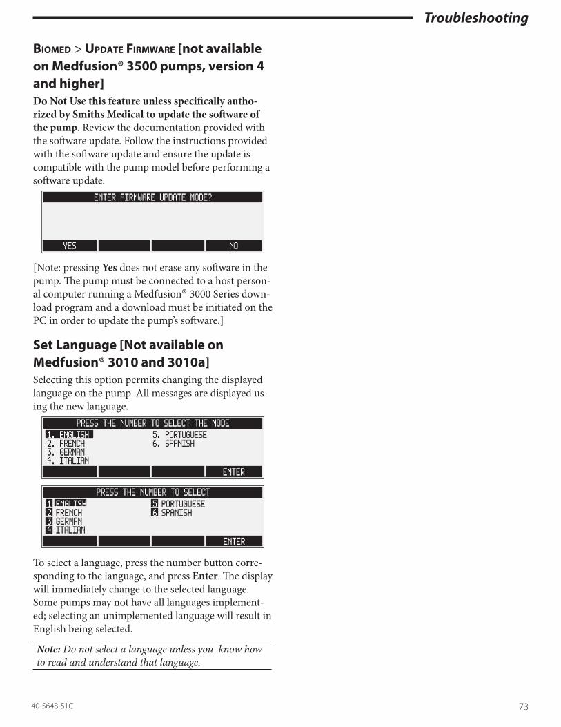
Troubleshooting
7340-5648-51C
Biomed > update firmware [not available on Medfusion® 3500 pumps, version 4 and higher] Do Not Use this feature unless specifically autho-rized by Smiths Medical to update the software of the pump. Review the documentation provided with the software update. Follow the instructions provided with the software update and ensure the update is compatible with the pump model before performing a software update.
ENTER FIRMWARE UPDATE MODE?
YES NO
[Note: pressing Yes does not erase any software in the pump. The pump must be connected to a host person-al computer running a Medfusion® 3000 Series down-load program and a download must be initiated on the PC in order to update the pump’s software.]
Set Language [Not available on Medfusion® 3010 and 3010a]Selecting this option permits changing the displayed language on the pump. All messages are displayed us-ing the new language.
PRESS THE NUMBER TO SELECT THE MODE
ENTER
1. ENGLISH 5. PORTUGUESE2. FRENCH 6. SPANISH3. GERMAN4. ITALIAN
PRESS THE NUMBER TO SELECT
ENTER
1 ENGLISH 5 PORTUGUESE2 FRENCH 6 SPANISH3 GERMAN4 ITALIAN
To select a language, press the number button corre-sponding to the language, and press Enter. The display will immediately change to the selected language. Some pumps may not have all languages implement-ed; selecting an unimplemented language will result in English being selected.
Note: Do not select a language unless you know how to read and understand that language.

Troubleshooting
74 40-5648-51C

Parts Replacement
7540-5648-51C
Section 4: Parts Replacement provides procedures for disassembly, parts replacement & re-assembly of the pump.
Maintenance warnings/cautionsObserve the following warnings and cautions while disassembling, replacing parts, and reassembling any Medfusion® 3000 Series pump.
After reassembling pump, use Retest Guidelines listed in the Calibration and Adjustment section to find any re-calibration or re-testing required before returning pump to use.
Service warnings • AC Power: The only means of removing AC
power is to disconnect the AC power cord. While the AC power cord is attached to the pump and plugged into an AC outlet, live mains voltage is present inside the pump.
• Battery Replacement: For continued protection against fire hazard, always replace battery pack with same type and model of battery specified in the labeling on the pump.
• Clean the Pump: Always clean the pump thor-oughly before performing maintenance on it. This is recommended by the United States Occupa-tional Safety & Health Administration (OSHA) as a protection from potential biohazard.
• Pump Maintenance: Only trained biomedical ser-vice personnel may repair, calibrate, and maintain this pump.
• Follow Manufacturer’s Maintenance Procedures: Always repair and maintain this pump following the manufacturer’s recommended instructions in this Service Manual.
• Repair Pump in ESD Controlled Work Area: The pump case should only be opened at a work-station with Electrostatic controls, including a grounded mat and wrist-strap.
• External DC Power: Any power source connected to the external DC jack must be IEC 60601-1 cer-tified for medical equipment: Type CF, Safety Class II. Connecting external power to the pump creates
a medical system; therefore, the user is responsible for compliance with IEC 60601-1 standards. Refer all questions to Smiths Medical Technical Service department.
• Collect Separately. There are potential health haz-ards associated with improper disposal of batter-ies, electronics, and contaminated (used) infusion sets and syringes. Dispose of used batteries, infu-sion sets, syringes, and other used accessories, or a pump that has reached the end of its useful life, in an environmentally safe manner, and according to any regulations that may apply.
Service cautions • Disconnect AC Mains & External DC Power:
Always disconnect the pump from AC Mains and from External DC power before disassembling the pump for maintenance.
• Handle Batteries with Care: Always handle the pump’s battery pack with care.
• Don’t Over-tighten Screws: Never over-tighten any screws in the pump. Unless otherwise speci-fied, you should torque all screws to 60 in- oz (0.42 Nm).
• Battery Disposal: Always dispose of exhausted NiMH batteries in compliance with all pertinent local, state, national, and international regulations. If unsure of correct methods for compliance, you may return battery packs to Smiths Medical for recycling.

Parts Replacement
76 40-5648-51C
Opening & closing the pump housingTools neededFor this disassembly procedure you will need:
• Torque screwdriver with a #1 Phillips head Always work at an electrostatic-controlled work sta-tion when disassembling the pump.
Opening the pump housing1. Unplug the AC power cord (also disconnect any
external DC power, if in use). 2. If the poleclamp is attached to the pump, you must
remove it before disassembling the pump. Remove the 2 flat head screws attaching the poleclamp bracket to bottom housing of the pump.
3. Remove the 2 flat head screws from the battery compartment cover, and then remove the cover.
4. Carefully remove battery pack from its compart-ment, and disconnect its cable from the intercon-nect board.
5. Remove the 2 pan head screws from the bottom housing of the pump.
6. Carefully separate the two halves of the pump housing (there are three snap tabs across the back).
7. Unplug the ribbon cable from J9 on the main board (in most cases the other end of this ribbon cable is glued or soldered into the interconnect board).
Closing the pump housing1. Before closing the pump housing, be sure the AC
and external DC power are disconnected, and the battery pack is removed.
2. Reconnect the ribbon cable joining the intercon-nect board and the main board at J9.
3. Be sure all wires are clear of pinch points when rejoining the housing halves.
4. There are 3 snap fit tabs and slots along the back-side of the housing. Align them and close the top & bottom housings together.
5. Screw in the 2 pan head screws which connect the
top & bottom housings. Torque these screws to 60 in oz (0.42 Nm).
6. Orient the battery pack with the circuit board and cable facing the rectangular cutout in the battery compartment.
7. Connect battery cable to the interconnect board. Slide the battery into the compartment.
8. Replace battery cover and secure it with 2 flathead screws. Torque these screws to 60 in oz (0.42 Nm).
9. If using the pole clamp, reattach it to the pump with the 2 flathead screws. Torque these screws to 160 in oz (1.13 Nm).
Follow retest guidelines listed in the Calibration and Adjustment section to verify pump functionality be-fore returning it to use.

Parts Replacement
7740-5648-51C
Battery packThis section defines the steps for removing and replac-ing the battery pack for the Medfusion® 3000 Series pump.
Tools neededFor this disassembly procedure you will need:
• Torque screwdriver with a Phillips head Always work at an electrostatic-controlled work sta-tion when disassembling the pump.
Removing the battery pack1. Before removing the battery pack, be sure the AC
mains and external DC power are disconnected.2. Remove the 2 flat head screws from the battery
compartment cover, and then remove the cover.3. Carefully remove battery pack from the compart-
ment, and gently disconnect (pull) its ribbon cable from the interconnect board.
Replacing the battery pack1. Unpack and carefully inspect the battery pack for
physical damage.2. Orient the battery pack with the circuit board and
cable facing the rectangular cutout in the battery compartment.
3. Connect battery cable into the interconnect board. Slide the battery into the compartment.
4. Replace battery cover and secure it with 2 flathead screws. Torque these screws to 60 in oz (0.42 Nm).
Verifying battery function after new battery replacementBefore returning the Medfusion® 3000 Series pump to service, you must verify the new battery is functioning nominally.
1. Connect the pump to AC power and verify the battery charge indicator is on.
2. Turn ON the pump. From the Main screen, select Biomed program Diagnostics and go to Monitor Battery Status.
3. Wait several minutes from power-on for readings to stabilize and then verify battery charge current is greater than 160 ma (if battery charge reading is
greater than 95%, then charge current is reduced to 50 ma or greater).
4. If < 0 ma, then check connections to AC power. [Note: negative current means the battery is dis-charging.]
5. If there is no battery information on the Monitor Battery Status screen, then check battery connec-tion on battery pack, or connection on the inter-connect board.
6. Turn off the pump, but leave it connected to AC power. Allow pump to recharge battery for at least 10 hours.
Follow retest guidelines listed in the Calibration and Adjustment section to verify pump functionality be-fore returning it to use.

Parts Replacement
78 40-5648-51C
Interconnect boardThis section defines the steps for removing and replac-ing the interconnect board for the Medfusion® 3000 Series infusion pump.
Tools neededFor this disassembly procedure you will need:
• Torque screwdriver with a Phillips head Always work at an electrostatic-controlled work sta-tion when disassembling the pump.
Removing the interconnect board1. Disconnect the pump from AC power source.2. Open the pump housing, remove battery pack,
and separate the top and bottom halves.3. Unplug the ribbon cable from J9 on the main
board (in most cases the other end of this ribbon cable is glued or soldered directly into the inter-connect board).
4. Disconnect the speaker cable from the intercon-nect board at J2.
5. Disconnect power supply cable from interconnect board at J3.
6. Remove the 2 pan head screws holding the board, and carefully remove the interconnect board from housing.
Replacing the interconnect board[Torque all screws to 60 in oz (0.42 Nm).]
1. Align the interconnect board with the threaded bosses, and press firmly into place.
2. Secure it with the 2 pan head screws. 3. Attach the speaker cable to connector J2, and the
power supply cable to connector J3. 4. Close the housing and secure with 2 pan head
screws. 5. Replace the battery pack, battery cover, and secure
with 2 flat head screws.
Verify interconnect board functionFollow retest guidelines listed in the Calibration and
Adjustment section to verify pump functionality be-fore returning it to use.
SpeakerThis section defines the steps for removing and replac-ing the speaker for the Medfusion® 3000 Series pump.
Tools NeededFor this disassembly procedure you will need:
• Torque screwdriver with a Phillips head Always work at an electrostatic-controlled work sta-tion when disassembling the pump.
Speaker removal1. Disconnect the pump from AC power source.2. Open the pump housing, remove battery pack,
and separate the top and bottom halves.3. Disconnect the speaker cable from the intercon-
nect board at J2.4. Remove the 2 pan head screws & shoulder (or
flat) washers holding the speaker to the case, and remove the speaker from housing.
Speaker replacement[Torque all screws to 60 in oz (0.42 Nm).]
1. Align the speaker on the round holder, and orient the cable to run toward the interconnect board.
2. Insert the 2 pan head screws & shoulder (or flat) washers and secure the speaker to the housing.
3. Close the housing and secure with 2 pan head screws.
4. Replace the battery pack, battery cover, and secure with 2 flat head screws.
Verifying speaker function After installing the new speaker, you only need to execute power-up testing to verify speaker function.
1. Connect the pump to AC power.2. Turn ON the pump. 3. Listen for power-on tones. Allow power-on self-
tests to complete. If no system failure messages appear, then the speaker is good.
Follow retest guidelines listed in the Calibration and Adjustment section to verify pump functionality be-fore returning it to use.

Parts Replacement
7940-5648-51C
AC power supplyThis section defines the steps for removing and replac-ing the AC Power Supply for the Medfusion® 3000 Series infusion pump.
Tools neededFor this disassembly procedure you will need:
• Torque screwdriver with a Phillips head & small flat blade
• 5mm open end wrench• ¼” nut driver
Always work at an electrostatic-controlled work sta-tion when disassembling the pump.
Removing AC power supply1. Disconnect the pump from AC power source.2. Open the pump housing, remove battery pack,
and separate the top and bottom halves.3. Remove the power supply shield.4. Disconnect the interconnect board cable from
power supply board at J2.5. Use small flat blade screwdriver to loosen the ter-
minals on the AC input wires, and disconnect the AC input wires from the power supply board at J1.
6. Remove the 2 pan head screws securing board to bottom housing, and remove AC Power Supply Board.
Replacing the AC power supply1. Align the AC Power Supply Board over the thread-
ed bosses, with J1 in line with the AC input cable.2. Secure the board with 2 pan head screws. Medfu-
sion® 3500BC: The earth wire from the AC inlet is to be secured at the AC supply mounting post furthest from the AC inlet. Torque to 60 in oz (0.42 Nm).
3. Connect the AC Input Wires to J1 and tighten the 2 terminal screws. Torque to 32 in oz (0.23 Nm).
4. Reconnect the interconnect board cable to J2.5. Reinstall the Power Supply Shield by sliding it into
the notched tabs.6. Close the housing and secure with 2 pan head
screws. Torque to 60 in oz (0.42 Nm).
7. Replace the battery pack, battery cover, and secure with 2 flat head screws. Torque to 60 in oz (0.42 Nm).
Verify AC power supply functionAfter you replace the AC Power Supply, you must verify its function with the following steps:
1, Plug the pump into AC power.2. Verify the AC power indicator lights.Follow retest guidelines listed in the Calibration and Adjustment section to verify pump functionality be-fore returning it to use.
AC input assemblyThis section defines the steps for removing and replac-ing the AC Input Assembly.
Tools NeededFor this disassembly procedure you will need:
• ¼” open end wrench • Torque screwdriver with a Phillips head & small
flat bladeAlways work at an electrostatic-controlled work sta-tion when disassembling the pump.
Removing AC input module assembly1. Disconnect the pump from AC power source.2. Open the pump housing, remove battery pack,
and separate the top and bottom halves.3. Remove power supply shield.4. Use small flat blade screwdriver to loosen the 2
screws on the Terminal Block of the power supply.5. With screwdriver & open end wrench, remove
the 2 flathead screws & Nylock nuts. Medfusion® 3500BC: Remove screw holding earth ground con-nection.
6. Slide the AC Input Module Assembly from the case.
Replacing AC input module assembly1. Install AC Input Module Assembly with 2 power

Parts Replacement
80 40-5648-51C
wires oriented toward the bottom of the housing. Medfusion® 3500BC: Install AC Input Module As-sembly with 3 wires, mains wires oriented toward the bottom of the housing, earth wire oriented toward the top.
2. Insert the 2 wires into the Terminal block on the power supply.
3. Tighten the 2 screws of the Terminal block. Torque to 32 in oz (0.23 Nm).
4. Secure with the 2 flathead screws & Nylock nuts. Medfusion® 3500BC: Reinstall the earth wire from the A/C inlet to the A/C supply mounting post fur-thest from the A/C inlet. Torque to 60 in oz (0.42 Nm).
5. Reinstall the Power Supply Shield by sliding it into the notched tabs.
6. Close the housing and secure with 2 pan head screws. Torque to 60 in oz (0.42 Nm).
7. Replace the battery pack, battery cover, and secure with 2 flat head screws. Torque to 60 in oz (0.42 Nm).
Verifying AC input assembly module function1. After you replace or repair the AC Input Assembly
Module, you must verify its nominal function with the following steps:
2. Plug the pump into AC power.3. Verify the AC power indicator lights.Follow retest guidelines listed in the Calibration and Adjustment section to verify pump functionality be-fore returning it to use.
Bottom housing plasticTools NeededFor this disassembly procedure you will need:
• ¼” open end wrench • Torque screwdriver with a Phillips head and
small flat bladeAlways work at an electrostatic-controlled work sta-tion when disassembling the pump.
Removing the bottom housing1. Disconnect the pump from AC power source.2. Open the pump housing, remove battery pack,
and separate the top and bottom halves.3. Unplug the ribbon cable from J9 on the main
board (in most cases the other end of this ribbon cable is glued or soldered directly into the inter-connect board).
4. Remove the Interconnect Board, the speaker, the Power Supply Shield, the AC Power Supply, and the AC Input Assembly using the procedures listed above.
Replacing the bottom housing1. The new case bottom should have rubber feet,
and IR lens already installed; however, new labels (included) need to be applied.
2. Record the serial number from the old case bot-tom. Take the new serial number label and type the serial number into the blank field on this label. Take the overlay supplied with the label, remove the backing and apply this overlay to cover/protect the typed serial number label.
3. Remove the backing on the typed serial number label, and apply this to the new case bottom.
4. Attach all new labels to the new case bottom, use the old bottom as a guide for label application.
5. Install the AC Power Supply, the AC Input As-sembly, the Power Supply Shield, the speaker, and the Interconnect Board into the replacement hous-ing using the procedures listed above.
6. Reconnect the ribbon cable to J9 on the main board in the top housing.
7. Close and secure the two halves of the housing,

Parts Replacement
8140-5648-51C
and reinstall the battery pack.Follow retest guidelines listed in the Calibration and Adjustment section to verify pump functionality be-fore returning it to use.
Main boardThis section defines the steps for removing and replac-ing the Main Board for the Medfusion® 3000 Series pump.
Tools neededFor this disassembly procedure you will need:
• Torque screwdriver with Phillips head & small flat head
Always work at an electrostatic-controlled work sta-tion when disassembling the pump.
Removing the main board1. Disconnect the pump from AC power source.2. Open the pump housing, remove battery pack,
and separate the top and bottom halves.3. Disconnect the interconnect ribbon cable from the
main board at J9.4. Loosen the 2 terminal block screws connecting the
fiber optic back light to the main board, then pull the fiber cable assembly from the terminal block.
5. Disconnect all cable connections on the main board. These include:
• Keypad ribbon cables at J10.• Motor cable at J3.• Position pot cable at J6.• Display cable at J12.• Ear clip sensor cable at J2.• Barrel clamp flex circuit at J4.• Plunger cable at J11 and unscrew the cable
clamp.6. If present, clip the wire tie securing the 2nd back-
light cable.7. Remove the 2 pan head screws securing main
board, and carefully remove the main board from housing.
Replacing the main board1. Place the new main board into the housing. It
should rest in the slot on the extrusion, and align the mounting holes with the 2 stand-offs.
2. Secure the main board with the 2 pan head screws. Torque to 60 in oz (0.42 Nm).

Parts Replacement
82 40-5648-51C
3. Reconnect all cable and wire connections on the main board. These include:
• Keypad ribbon cables at J10.• Motor cable at J3.• Position pot cable at J6.• Display cable at J12.• Ear clip sensor cable at J2.• Barrel clamp flex circuit at J4.• Plunger cable at J11. Install the cable clamp over
the exposed braid of the plunger cable and se-cure with small pan head screw. Torque screw to 16 in oz (0.12 Nm).
4. If a 2nd fiber optic tail is present on the backlight, connect its cable to J8 on the main board. If you are replacing an older main board (with a black connector at J8), you can discard the backlight adapter cable. After completing the next step, an-chor both fiber optic tails to the main board with a wire tie.
5. Insert the backlight wires into the main board terminal block. Screw the terminal connector onto the leads with the flat edge of the LED lens toward the outside edge of the board. Torque terminal block screws to 32 in oz (0.23 Nm).
Note: If you reverse the leads during installation, the backlight will not turn on. You may wish to loosely reassemble the case halves, plug in the battery, and power up pump to check the backlight.
6. Close and secure the two halves of the housing and reinstall the battery pack.
7. Complete recalibration and reconfiguration is required when replacing main board.
Follow retest guidelines listed in the Calibration and Adjustment section to verify pump functionality be-fore returning it to use.
Drive train assemblyTools NeededFor this disassembly procedure you will need:
• Torque screwdriver with a Phillips head & ¼” nut drive
• ¼” wrench• .002” (.051mm) shim
Always work at an electrostatic-controlled work sta-tion when disassembling the pump.
Motor unit (motor, worm, worm gear)Removal1. Open pump housing per pump housing section
above, and set up the case top section with the handle down and main board facing up.
2. Remove the main board per section above.3. Squeeze the plunger lever and fully extend the
plunger head away from the case.4. Remove pan head screws and standoffs holding
the extrusion (drive train assembly). Remove pan head screws and Nylock nuts holding barrel clamp assembly to extrusion.
5. Partially slide extrusion out of case until motor mount screws are accessible.
Disassemble motor unit as required:
1. For motor or worm, remove two pan head screws and Nylock nuts holding the motor. Remove mo-tor and worm. Worm pulls straight off of motor shaft.
2. For worm gear (plastic gear on leadscrew), remove e-clip. Pull gear straight off of leadscrew shaft.
ReplacementReassemble motor unit1. For motor/worm, slide worm onto motor shaft.
Rotate motor to align mounting holes with holes in motor plate. Ensure the motor is positioned for the wires to properly reach the main board. Secure motor with two pan head screws and Nylock nuts. Torque to 100 in oz (0.71 Nm).

Parts Replacement
8340-5648-51C
2. For worm gear, align “D” with shaft and press onto leadscrew until centered over worm. Attach e-clip.
3. Carefully slide the extrusion (drive train assembly) back into case.
4. Ensure right end plate on extrusion does not dam-age ear clip sensor.
5. Ensure plunger cable comes out between middle boss and boss by the motor.
6. Slide keypad ground tab (black side toward extru-sion) between boss by the motor and extrusion.
7. Secure extrusion with 3 standoffs and 3 pan head screws. Torque to 100 in oz (0.71 Nm).
8. Secure the barrel clamp assembly to the extrusion with 2 pan head screws and Nylock nuts. Torque to 100 in oz (0.71 Nm).
9. Reinstall main board per main board section above.
10. Close pump housing per housing section above.
Position potentiometerRemoval1. Open pump housing per pump housing section
above, and setup the case top section with the handle down and main board facing up.
2. Remove the main board per section above.3. Squeeze the plunger lever and fully extend the
plunger head away from the case.4. Remove pan head screws and standoffs holding
the extrusion (drive train assembly). Remove pan head screws and Nylock nuts holding barrel clamp assembly to extrusion.
5. Partially slide extrusion out of case until flat head screw in right end plate is accessible.
6. Remove small flat head screw holding position potentiometer (pot).
7. On the carriage remove pan head screw, washer, and Nylock nut holding the post of the pot. (It may be necessary to reposition carriage by moving the plunger head.)
8. Remove three flat head screws holding motor as-sembly on extrusion and rotate out of way.
9. Slide position pot out of the extrusion.
Replacement1. Slide new position pot into extrusion.2. Clean small flat head screw (or use a new screw),
apply Loctite 242 (mild thread-locking adhesive) to screw, and secure pot to right end plate of extrusion assembly. Torque only to 16 in oz (0.12 Nm).
3. Secure motor assembly on extrusion with three flat head screws. Torque to 100 in oz (0.71 Nm).
4. Slide post of position pot up to carriage. Insert pan head screw through hole in carriage arm, then through washer. Start the Nylock nut onto the screw. Insert 0.002” shim between pot’s post and the washer, then tighten the nut until slack is removed. Do not over-tighten nut. Remove shim and check if flat washer can move (spin) freely, if not loosen nut slightly.
5. Carefully slide the extrusion (drive train assembly) back into case.
6. Ensure right end plate on extrusion does not dam-age ear clip sensor.
7. Ensure plunger cable comes out between middle boss and boss by the motor.
8. Slide keypad ground tab (black side toward extru-sion) between boss by the motor and extrusion.
9. Secure extrusion with 3 standoffs and 3 pan head screws. Torque to 100 in oz (0.71 Nm).
10. Secure the barrel clamp assembly to the extrusion with 2 pan head screws and Nylock nuts. Torque to 100 in oz (0.71 Nm).
11. Reinstall main board per main board section above.
12. Close pump housing per housing section above.

Parts Replacement
84 40-5648-51C
Clutch assemblyTools neededFor this disassembly procedure you will need:
• Torque screwdriver with a Phillips head & ¼” nut drive
• ¼” wrench• .002” (.051mm) shim
Always work at an electrostatic-controlled work sta-tion when disassembling the pump.
LeadscrewRemoval1. Open pump housing per pump housing section
above, and setup the case top section with the handle down and main board facing up.
2. Remove the main board per section above.3. Squeeze the plunger lever and fully extend the
plunger head away from the case.4. Remove pan head screws and standoffs holding
the extrusion (drive train assembly). Remove pan head screws and Nylock nuts holding barrel clamp assembly to extrusion.
5. Partially slide extrusion out of case until Nylock nut holding leadscrew on right end plate is acces-sible.
6. Pull the plastic worm gear off the end of leadscrew near motor.
7. Remove three flat head screws holding motor as-sembly on extrusion, and pull off motor assembly.
8. Slide carriage rod out of the carriage.9. Move the plunger head/carriage in about 1”
(2.5cm) from the right end plate. Hold onto the “D” side of the leadscrew and use ¼” wrench to remove Nylock nut holding leadscrew and the flat brass washer.
10. Slide extrusion in slightly until leadscrew clears right end plate, then pull off the thrust bearings.
11. Squeeze the plunger lever to open clutch and pull leadscrew out of carriage.
Replacement1. Apply light coating of STP poly-plus (lithium)
grease to leadscrew. Squeeze plunger lever to open clutch and insert leadscrew until it sticks slightly through the carriage.
2. Install thrust bearing assembly (flat washer, bear-ings, flat washer) onto end of leadscrew and pull on plunger head to feed leadscrew through the right end plate. Ensure nylon shoulder washer is still in place on right end plate.
3. Place brass washer over the leadscrew and start Nylock nut. Insert .002” shim between the brass washer and shoulder washer and tighten the nut. Do not over-tighten nut. Remove shim and check if brass washer can move (spin) freely, if not loosen nut slightly.
4. Slide carriage rod through carriage and seat into hole in right end plate.
5. Slide motor assembly over leadscrew and align carriage rod with motor assembly bracket. Secure motor assembly on extrusion with three flat head screws. Torque to 100 in oz (0.71 Nm).
6. Align “D” of worm gear with leadscrew shaft and press onto leadscrew until gear is centered over the motor worm.
7. Carefully slide the extrusion (drive train assembly) back into case.
8. Ensure right end plate on extrusion does not dam-age ear clip sensor.
9. Ensure plunger cable comes out between middle boss and boss by the motor.
10. Slide keypad ground tab (black side toward extru-sion) between boss by the motor and extrusion.
11. Secure extrusion with 3 standoffs and 3 pan head screws. Torque to 100 in oz (0.71 Nm).
12. Secure the barrel clamp assembly to the extrusion with 2 pan head screws and Nylock nuts. Torque to 100 in oz (0.71 Nm).
13. Reinstall main board per main board section above.
14. Close pump housing per housing section above.
Clutch or clutch camTools neededFor this disassembly procedure you will need:
• Safety glasses

Parts Replacement
8540-5648-51C
• Needle nose pliers
Removal1. Remove leadscrew per procedure above.2. Use needle nose pliers (or hemostats) to remove
e-ring from cam in carriage plate.3. Using ¼” open end wrench and Phillips screw
driver, remove three pan head screws with Nylock nuts holding the carriage plate.
4. Use needle nose pliers to remove either:
• the clutches, use caution in separating clutches because of spring.
• the cam, pull straight out and separate from square shaft.
Replacement1. For replacement of:
• the cam, first ensure the shaft is seated to the plunger lever, then press the cam gear on the shaft.
• the clutches, put the clutch halves together (closed) and press the spring into place, then slide the clutch halves into the carriage.
2. Feed the pan head screws though the carriage then the carriage plate, then secure with nylon nuts. Nuts should be on top of the carriage plate not the carriage. Torque to 100 in oz (0.71 Nm).
3. Snap e-ring over cam sticking through carriage plate.
4. Replace leadscrew per procedure above.
Plunger cableRemoval1. Remove leadscrew per procedure above.2. Using ¼” open end wrench and Phillips screw
driver, remove three pan head screws with Nylock nuts holding the carriage plate. Pull plate with cam and square shaft attached.
3. Open plunger case right per procedure below.4. Unplug the plunger cable from plunger board and
pull cable out of slot in force mount and plunger tube.
5. At the carriage, turn plunger cable connector in line with the cable, and pull cable out through
plunger head.
Replacement1. Take the new plunger cable, with the smaller
exposed braid area towards the carriage, turn con-nector in line with the cable, then thread the cable through the plunger tube.
2. Plug the cable into the plunger board, then press the braided portion into the slot of the force mount and plunger tube. This should leave about 2” (5cm) of cable sticking out the notched end of the plunger tube.
3. Press the square shaft on the cam, the cam through the carriage plate (check orientation of plate) and snap the e-ring on the cam.
4. Slide carriage plate with clutch cam and shaft into plunger tube.
5. Feed the pan head screws though the carriage then the carriage plate, then secure with nylon nuts. Nuts should be on top of the carriage plate not the carriage. Torque to 100 in oz (0.71 Nm).
6. Close plunger case per procedure below.7. Replace lead screw per procedure above.

Parts Replacement
86 40-5648-51C
LCD and backlightThis section defines the steps for removing and replac-ing the LCD Display and Backlight for the Medfu-sion® 3000 Series pump.
Tools NeededFor this disassembly procedure you will need:
• ¼” open end wrench • Torque screwdriver with Phillips head & small
flat head Always work at an electrostatic-controlled work sta-tion when disassembling the pump.
Removing LCD and/or backlight assembly1. Disconnect the pump from AC power source.2. Open the pump housing, remove battery pack,
and separate the top and bottom halves.3. Disconnect the display cable from the main board
at J12.4. Use small flat blade screwdriver to loosen the 2
screws connecting the fiber optic back light to the main board. Then pull the fiber cable assembly from the terminal block.
5. If the back light has a 2nd fiber optic tail, cut the wire tie anchoring its connecting cable and sepa-rate the 2nd tail from the connecting cable.
6. With ¼” open end wrench, remove the 2 Nylock nuts securing the display.
7. Carefully lift the display assembly from the top housing.
8. Slide the back light and spacer from the display assembly.
Replacing the LCD and/or backlight assembly1. Remove the protective plastic film from the new
display’s glass. 2. Remove the tape which holds the plastic spacer
inside the new display, and slide out the spacer. Discard the white plastic spacer.
3. If the backlight has one fiber optic tail, then you will use two clear plastic spacers in the next step.
If your backlight has two fiber optic tails, then you will use only one clear plastic spacer in the next step.
4. Place the clear plastic spacer(s) on top of the backlight with the white side of the back light fac-ing up and the silver side down.
5. Gently slide the back light and spacer together into the display with the clear plastic spacer toward the display glass.
6. Orient the display with the back light tail on the side with the keypad cables. Verify there is not lint or dirt on the display.
7. Slide the display onto the ribs in the top of the top housing and over the spacers/studs. Secure the display assembly with the 2 Nylock nuts and tighten with ¼” wrench.
8. Reconnect the display cable to the main board at J12.
9. If a 2nd fiber optic tail is present on the backlight, clip the lead on the LED of the shorter fiber optic tail to match the length of the shorter tail’s LED on the removed backlight. Note: the longer fiber optic tail’s LED requires longer leads. Connect the shorter fiber optic tail to the round connector on the cable. Be sure to orient the lead closest to the flat edge of the LED into the terminal touching the MELF resistor embedded in the round connector. After completing the next step, anchor both fiber optic tails to the main board with a wire tie.
10. Insert the back light wires into the main board terminal block. (When replacing the back light, trim the LED leads to about ½” in length.] Screw the terminal connector onto the leads with the flat edge of the LED lens toward the outside edge of the board. Torque terminal block screws to 32 in oz (0.23 Nm).
Note: If you reverse the leads during installation, the backlight will not turn on. You may wish to loosely reassemble the case halves, plug in the battery, and power up pump to check the backlight.
11. Close and secure the two halves of the housing and reinstall the battery pack.

Parts Replacement
8740-5648-51C
Verify LCD & backlight assembly function1. Plug the pump into AC power and turn it ON.2. Watch the screen during startup and self-testing.
[Note: you may wish to adjust the display contrast, see chapter on calibration and adjustment.]
3. After self-testing completes, set the pump in a darkened area and verify the back light is func-tioning.
Follow retest guidelines listed in the Calibration and Adjustment section to verify pump functionality be-fore returning it to use.
KeypadThis section defines the steps for removing and replac-ing the Keypad.
Tools neededFor this disassembly procedure you will need:
• ¼” open end wrench • Torque screwdriver with a Phillips head & small
flat bladeAlways work at an electrostatic-controlled work sta-tion when disassembling the pump.
Removing the keypad1. Disconnect the pump from AC power source.2. Open the pump housing, remove battery pack,
and separate the top and bottom halves.3. Disconnect the interconnect ribbon cable from J9
on the main board.4. Loosen the 2 terminal block screws connecting
the fiber-optic backlight to the main board. Then, carefully pull the leads from the connector. If a 2nd backlight LED is present, disconnect its cable at the main board and clip the wire tie securing it to the main board.
5. Disconnect the keypad cables at J10 on the main board.
6. Disconnect the display cable at J12 on the main board.
7. Remove the 2 pan head screws securing the main board, and then loosen the main board. It is not necessary to remove the main board, or discon-nect all cables from it, to access the keypad.
8. With ¼” open end wrench, remove the 2 Nylock nuts securing the display board, and remove the display from the top housing.
9. With ¼” open end wrench, remove one hex head standoff nearest to the motor, and carefully slide out the keypad ground tab from between the top housing boss and the extrusion.
10. Press on inside of clear lens (window) to loosen keypad and peel keypad from top housing.

Parts Replacement
88 40-5648-51C
Replacing the keypadCAUTION: Keypad is NOT Flexible: Whenever handling the keypad, always ensure it remains flat. Bending the keypad can damage keys or break LED contacts.
1. Clean the clear lens with a soft cloth. Ensure there is no lint or fingerprints on the lens.
2. Ensure inside of new keypad window is clear of lint or fingerprints.
3. Remove backing from the keypad. Feed the 3 key-pad cables through the housing window. Slide the clear lens into the cutout of the case top.
4. Align the keypad and carefully press into recess in the case top. Keep the keypad as flat as possible.
5. Slide the keypad ground tab between the extrusion and the top housing boss. Be sure the black side of the tab faces toward the extrusion. Replace the hex head standoff into the extrusion securing the ground tab. Torque to 100 in oz (0.71 Nm).
6. Slide the display assembly into the ribs on the top housing, and secure it with 2 Nylock nuts.
7. Reposition the main board and secure with 2 pan head screws. Torque to 60 in oz (0.42 Nm).
8. Reconnect display cable to J12, keypad cables to J10.
9. Insert the back light wires into the main board terminal block. (When replacing the back light, trim the LED leads to about ½” in length.] Screw the terminal connector onto the leads with the flat edge of the LED lens toward the outside edge of the board. Torque terminal block screws to 32 in oz (0.23 Nm). If present, connect the 2nd back-light LED’s cable to J8.
Note: If you reverse the leads during installation, the backlight will not turn on. You may wish to loosely reassemble the case halves, plug in the battery, and power up pump to check the backlight.
10. If a 2nd backlight LED is present, secure the fiber optic cable to the main board with a wire tie.
11. Close the pump case and reinstall the battery pack.Follow retest guidelines listed in the Calibration and Adjustment section to verify pump functionality be-fore returning it to use.
Syringe barrel clamp as-semblyTools NeededFor this disassembly procedure you will need:
• Torque screwdriver with a Phillips head & 1/16” hex head
• ¼” wrench• Small vise-grip pliers
Always work at an electrostatic-controlled work sta-tion when disassembling the pump.
Barrel clamp headRemoval1. Lift barrel clamp head until screw is accessible
then use vise grips to clamp near base of barrel clamp rod to hold it in place.
2. Using a 1/16” hex wrench, remove hex head screw from barrel clamp head.
3. Pull barrel clamp head off of the barrel clamp rod.
Replacement1. Align the hole in the barrel clamp rod with the
barrel clamp head, and press the head onto the rod.
2. Secure the barrel clamp head with the 1/16” hex head screw. Torque to 60 in oz (0.42 Nm)
Verify Function1. Verify barrel clamp head moves up and down, and
will rotate when fully extended.Follow retest guidelines listed in the Calibration and Adjustment section to verify pump functionality be-fore returning it to use.
Barrel clamp body assembly Removal1. Remove barrel clamp head per above.2, Open pump housing per pump housing section
above.3. Using a ¼” wrench and Phillips screwdriver,
remove two pan head screws with Nylock nuts which hold the barrel clamp assembly. These

Parts Replacement
8940-5648-51C
screws are located on the right end plate of the drive train assembly.
4. Unplug the barrel clamp flex circuit from J4 of the main board.
5. Gently slide barrel clamp assembly out of the case avoiding the fingers extending from the right end plate around the plunger tube.
6. Remove small screw holding the pot to the barrel clamp assembly.
7. Carefully lift pot up off alignment bosses and out of fingers on the slide.
Replacement1. Align new pot into fingers of slide on the barrel
clamp assembly and press onto bosses.2. Secure pot with small screw. Tighten until screw is
flush with pot. [Do not over-tighten.]3. Carefully slide barrel clamp body assembly into
case. Push the rod through the hole in top of the case.
4. Secure barrel clamp assembly with two pan head screws with Nylock nuts. Torque to 100 in oz (0.71 Nm).
5. Plug barrel clamp flex circuit into J4 of the main board.
6. Close pump housing per housing section above.7. Replace barrel clamp head and verify function per
above.
Ear clip, handle & guideTools NeededFor this disassembly procedure you will need:
• Torque screwdriver with a Phillips head & ¼” nut drive
• Needle nose pliers (two pairs)Always work at an electrostatic-controlled work sta-tion when disassembling the pump.
Ear clip Removal1. Open pump housing per pump housing section
above, and setup the case top section with the handle down and main board facing up.
2. Use one pair of needle nose pliers to press the ear clip sleeve towards the case wall, then use a sec-ond set of pliers (or hemostats) to pull the e-ring off of the ear clip. [Note, on older pumps sleeve is not present, so use 1st set of pliers to pull spring towards the case wall.]
3. Slide the ear clip out of the top housing assembly.
Replacement1. Partially insert new ear clip through side of case,
then slide the spring onto shaft of ear clip.2. Slide sleeve over ear clip with hollow end of sleeve
towards the spring.3. Ensure the ear clip faces the “V” groove in the case
top, then press the ear clip into the case. Use one pair of needle nose pliers to compress the sleeve (and/or spring) and use a second set of needle nose (or hemostats) to snap e-ring into groove on the ear clip.
4. Pull on the ear clip and release it. Verify that the ear clip moves smoothly out and is pulled back flush to the case by the spring when released.
5. Close pump housing per housing section above.
Ear clip optical sensor Removal1. Open pump housing per pump housing section
above, and setup the case top section with the

Parts Replacement
90 40-5648-51C
handle down and main board facing up.2. Remove the main board per section above.3. Squeeze the plunger lever and fully extend the
plunger head away from the case.4. Remove pan head screws and standoffs holding
the extrusion (drive train assembly). Remove pan head screws and Nylock nuts holding barrel clamp assembly to extrusion.
5. Partially slide extrusion out of case until ear clip sensor is visible.
6. Remove pan head screw holding sensor and re-move the ear clip optical sensor.
Replacement1. On the new ear clip sensor, look at the old sensor
then use wire cutters to carefully cut a portion of the plastic tab/mounting hole to allow clearance for the display connector.
2. Slide ear clip sensor onto post in case top, with grey side of sensor away from the display.
3. Secure the sensor with the pan head screw. Torque to 100 in oz (0.71 Nm).
4. Carefully slide the extrusion (drive train assembly) back into case.
5. Ensure right end plate on extrusion does not dam-age ear clip sensor.
6. Ensure plunger cable comes out between middle boss and boss by the motor.
7. Slide keypad ground tab (black side toward extru-sion) between boss by the motor and extrusion.
8. Secure extrusion with 3 standoffs and 3 pan head screws. Torque to 100 in oz (0.71 Nm).
9. Secure the barrel clamp assembly to the extrusion with 2 pan head screws and Nylock nuts. Torque to 100 in oz (0.71 Nm).
10. Reinstall main board per main board section above.
11. Close pump housing per housing section above.
HandleRemoval1. Open pump housing per pump housing section
above, and setup the case top section with the handle down and main board facing up.
2. Remove the main board per section above.3. Squeeze the plunger lever and fully extend the
plunger head away from the case.4. Remove pan head screws and standoffs holding
the extrusion (drive train assembly). Remove pan head screws and Nylock nuts holding barrel clamp assembly to extrusion.
5. Partially slide extrusion out of case until two handle screws are visible.
6. Remove two pan head screw holding handle and remove the handle.
Replacement1. Place new handle on case top and secure with two
pan screws with washers through the inside of case.
2. Carefully slide the extrusion with plunger tube back into the case.
3. Carefully slide the extrusion (drive train assembly) back into case.
4. Ensure right end plate on extrusion does not dam-age ear clip sensor.
5. Ensure plunger cable comes out between middle boss and boss by the motor.
6. Slide keypad ground tab (black side toward extru-sion) between boss by the motor and extrusion.
7. Secure extrusion with 3 standoffs and 3 pan head screws. Torque to 100 in oz (0.71 Nm).
8. Secure the barrel clamp assembly to the extrusion with 2 pan head screws and Nylock nuts. Torque to 100 in oz (0.71 Nm).
9. Reinstall main board per main board section above.
10. Close pump housing per housing section above.
Tubing guideRemoval1. Open pump housing per pump housing section
above, and setup the case top section with the handle down and main board facing up.
2. Remove the main board per section above.3. Squeeze the plunger lever and fully extend the
plunger head away from the case.

Parts Replacement
9140-5648-51C
4. Remove pan head screws and standoffs holding the extrusion (drive train assembly). Remove pan head screws and Nylock nuts holding barrel clamp assembly to extrusion.
5. Partially slide extrusion out of case until three tub-ing guide screws are visible.
6. Remove pan head screw holding tubing guides and remove the tubing guides. Note orientation of each tubing guide.
Replacement1. Place each tubing guide onto case top and secure
with a pan head screw and nylon washer. The bumps on the case top help ensure correct orienta-tion of each guide. Torque to 60 in oz (0.42 Nm).
2. Carefully slide the extrusion (drive train assembly) back into case.
3. Ensure right end plate on extrusion does not dam-age ear clip sensor.
4. Ensure plunger cable comes out between middle boss and boss by the motor.
5. Slide keypad ground tab (black side toward extru-sion) between boss by the motor and extrusion.
6. Secure extrusion with 3 standoffs and 3 pan head screws. Torque to 100 in oz (0.71 Nm).
7. Secure the barrel clamp assembly to the extrusion with 2 pan head screws and Nylock nuts. Torque to 100 in oz (0.71 Nm).
8. Reinstall main board per main board section above.
9. Close pump housing per housing section above.
Plunger case assembly Tools neededFor this disassembly procedure you will need:
• Torque screwdriver with a Phillips head & 2.5mm hex head
• Needle nose pliers• Safety glasses
Always work at an electrostatic-controlled work sta-tion when disassembling the pump.
Plunger leverRemoval1. Remove pan head screw from lever.2. Pull plunger lever off the lever gear.
Replacement1. Position new plunger lever onto lever gear and se-
cure with pan head screw. Torque to 60 in oz (0.42 Nm).
Plunger case disassemblyWARNING: While servicing the Medfusion® 3000 Series infusion pump you should wear safety glasses as it contains springs and other small parts which may be a hazard.
Disassembly1. Stand the pump up on its left side so that the
plunger assembly points vertically up. Squeeze the plunger lever and position the plunger driver for disassembly.
2. Remove three pan head screws holding the plung-er case halves together (do not remove screw on lever).
3. Remove the plunger case right and remove the plunger case seal. The lever gear will be attached to the plunger case right. The square shaft may come out with plunger case right; if so, pull the shaft out of the lever gear and slide the shaft down the plunger tube into gently press into the cam.
Reassembly1. Remove any slack in movement of square shaft by

Parts Replacement
92 40-5648-51C
turning counter-clockwise. With plunger lever po-sitioned up against long rib on plunger case right, join the two case halves together pressing the lever gear over the square shaft.
2. Start the three pan head screws into the plunger case halves, with the long screw into the tall rib of the case.
3. Before tightening, press the plunger case seal into the gaps between the case halves. Ensure the seal is positioned properly between the halves then tighten the plunger case screws. Torque to 60 in oz (0.42 Nm).
Follow retest guidelines listed in the Calibration and Adjustment section to verify pump functionality be-fore returning it to use.
Cam gear and timing plateWARNING: While servicing the Medfusion® 3000 Series infusion pump you should wear safety glasses as it contains springs and other small parts which may be a hazard.
Removal1. Open the plunger case halves per above.2. Lift cam gear off of pin.3. Remove push block.4. Press timing plate upward and lift carefully to
remove timing plate spring and timing plate. Note, the timing plates are asymmetrical (left and right handed).
Replacement1. Rotate the right flipper until it stops against the
“V” groove on the plunger case.2. Insert the spring into the timing plate right. Slide
spring over the post in the side wall of the plunger case.
3. Slowly lower timing plate into the plunger case slot – as far down the slot as possible toward the optical sensor on the plunger board – while lining up the gears.
4. Repeat this process for the left flipper and left tim-ing gear.
5. Place the push block on top of the timing plate6. Place cam gear over pin (check assembly drawing
for orientation) and up against push block.7. Close plunger case halves per above.
Flipper and flipper gearRemoval1. Disassemble plunger case and remove timing
plates per above.2. Use the needle nose pliers to compress the flipper
shaft inside the flipper gear. Gently pull on the flipper while compressing the shaft.
3. Slide the O-ring seal off of the flipper. (Inspect the O-ring replace if damaged; otherwise, clean with soap and water.)
Replacement1. Slide O-ring seal over new flipper.2. Insert flipper through the plunger case and snap
onto the flipper gear. (Ensure gear recess faces out from case – if gear is installed incorrectly then flipper will not snap in place. If flipper gear is damaged replace flipper gear.)
3. Install timing plates per above and reassemble plunger case halves.
Plunger boardNote: Ensure plunger head is fully extended away from pump housing before starting.
Additional tools neededFor this disassembly procedure you may also need:
• .002” (.051mm) shim
Removal1. Disassemble plunger case and remove timing
plates per above.2. Gently pull on the plunger cable unplugging it
from connector J2. Unplug force sensor cable from J1 on plunger board.
3. Using a Phillips screwdriver, remove pan head screw with washer from the force mount assembly.
4. On newer assemblies it is not necessary to remove float plate seal and float plate. Gently try to pull plunger case left towards the pump. If it comes apart skip to step 7 below, otherwise remove float plate seal and float plate.
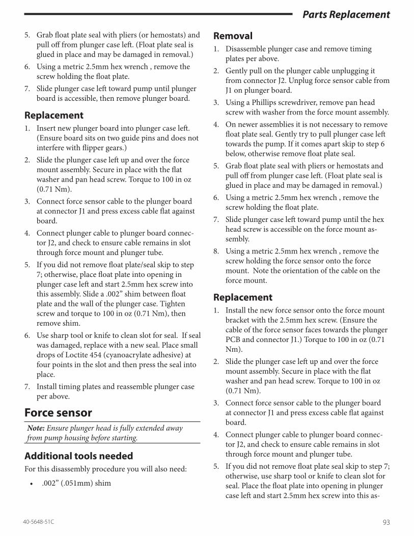
Parts Replacement
9340-5648-51C
5. Grab float plate seal with pliers (or hemostats) and pull off from plunger case left. (Float plate seal is glued in place and may be damaged in removal.)
6. Using a metric 2.5mm hex wrench , remove the screw holding the float plate.
7. Slide plunger case left toward pump until plunger board is accessible, then remove plunger board.
Replacement1. Insert new plunger board into plunger case left.
(Ensure board sits on two guide pins and does not interfere with flipper gears.)
2. Slide the plunger case left up and over the force mount assembly. Secure in place with the flat washer and pan head screw. Torque to 100 in oz (0.71 Nm).
3. Connect force sensor cable to the plunger board at connector J1 and press excess cable flat against board.
4. Connect plunger cable to plunger board connec-tor J2, and check to ensure cable remains in slot through force mount and plunger tube.
5. If you did not remove float plate/seal skip to step 7; otherwise, place float plate into opening in plunger case left and start 2.5mm hex screw into this assembly. Slide a .002” shim between float plate and the wall of the plunger case. Tighten screw and torque to 100 in oz (0.71 Nm), then remove shim.
6. Use sharp tool or knife to clean slot for seal. If seal was damaged, replace with a new seal. Place small drops of Loctite 454 (cyanoacrylate adhesive) at four points in the slot and then press the seal into place.
7. Install timing plates and reassemble plunger case per above.
Force sensorNote: Ensure plunger head is fully extended away from pump housing before starting.
Additional tools neededFor this disassembly procedure you will also need:
• .002” (.051mm) shim
Removal1. Disassemble plunger case and remove timing
plates per above.2. Gently pull on the plunger cable unplugging it
from connector J2. Unplug force sensor cable from J1 on plunger board.
3. Using a Phillips screwdriver, remove pan head screw with washer from the force mount assembly.
4. On newer assemblies it is not necessary to remove float plate seal. Gently try to pull plunger case left towards the pump. If it comes apart skip to step 6 below, otherwise remove float plate seal.
5. Grab float plate seal with pliers or hemostats and pull off from plunger case left. (Float plate seal is glued in place and may be damaged in removal.)
6. Using a metric 2.5mm hex wrench , remove the screw holding the float plate.
7. Slide plunger case left toward pump until the hex head screw is accessible on the force mount as-sembly.
8. Using a metric 2.5mm hex wrench , remove the screw holding the force sensor onto the force mount. Note the orientation of the cable on the force mount.
Replacement1. Install the new force sensor onto the force mount
bracket with the 2.5mm hex screw. (Ensure the cable of the force sensor faces towards the plunger PCB and connector J1.) Torque to 100 in oz (0.71 Nm).
2. Slide the plunger case left up and over the force mount assembly. Secure in place with the flat washer and pan head screw. Torque to 100 in oz (0.71 Nm).
3. Connect force sensor cable to the plunger board at connector J1 and press excess cable flat against board.
4. Connect plunger cable to plunger board connec-tor J2, and check to ensure cable remains in slot through force mount and plunger tube.
5. If you did not remove float plate seal skip to step 7; otherwise, use sharp tool or knife to clean slot for seal. Place the float plate into opening in plunger case left and start 2.5mm hex screw into this as-

Parts Replacement
94 40-5648-51C
sembly. Slide a .002” shim between float plate and the wall of the plunger case. Tighten screw and torque to 100 in oz (0.71 Nm), then remove shim.
6. If seal was damaged, replace with a new seal. Place small drops of Loctite 454 (cyanoacrylate adhe-sive) at four points in the slot and then press the seal into place.
7. Install timing plates and reassemble plunger case per above.
Left plunger caseNote: Ensure plunger head is fully extended away from pump housing before starting.
Additional tools neededFor this disassembly procedure you will also need:
• .002” (.051mm) shim
Removal1. Disassemble plunger case and remove timing
plates per above.2. Remove plunger flippers and gears per above.3. Gently pull on the plunger cable unplugging it
from connector J2. Unplug force sensor cable from J1 on plunger board.
4. Using a Phillips screwdriver, remove pan head screw with washer from the force mount assembly.
5. On newer assemblies it is not necessary to remove float plate seal. Gently try to pull plunger case left towards the pump. If it comes apart skip to step 8 below, otherwise remove float plate seal.
6. Grab float plate seal with pliers or hemostats and pull off from plunger case left. (Float plate seal is glued in place and may be damaged in removal.)
7. Using a metric 2.5mm hex wrench , remove the screw holding the float plate.
8. Slide plunger case left toward pump until the two small flat head screws are accessible on the force mount. Unscrew two flat head screws on force mount. Pull plunger cable out of slot on force mount bracket and plunger tube. Slide off the force mount assembly from the plunger tube.
9. Slide plunger case left off of plunger tube.
Replacement1. Install flippers and flipper gears per above into
new plunger case left.2. Transfer plunger board into new plunger case.3. Slide new plunger case left onto plunger tube. (En-
sure case is correctly oriented.)4. Thread plunger cable through force mount as-
sembly and slide assembly onto plunger tube align screw holes and cable slot. Apply (mild thread-locking adhesive) Loctite 242 to flat head screws and secure the force mount to the plunger tube. Torque to 100 in oz (0.71 Nm). [Be careful not to cross-thread screws.]
5. Slide the plunger case left up and over the force mount assembly. Secure in place with the flat washer and pan head screw. Torque to 100 in oz (0.71 Nm).
6. Connect force sensor cable to the plunger board at connector J1 and press excess cable flat against board.
7. Press plunger cable into slot though plunger tube, force mount, and plunger case left. Ensure ex-posed braid of cable touches metal on force mount or plunger tube.
8. Connect plunger cable to plunger board connec-tor J2, and check to ensure cable remains in slot through force mount and plunger tube.
9. If you did not remove the float plate seal, skip to step 11. Place the float plate into opening in plung-er case left and start 2.5mm hex screw into this as-sembly. Slide a .002” shim between float plate and the wall of the plunger case. Tighten screw and torque to 100 in oz (0.71 Nm), then remove shim.
10. Use a new seal. Place small drops of Loctite 454 (cyanoacrylate adhesive) at four points in the slot and then press the seal into place.
11. Install timing plates and reassemble plunger case per above.

Calibration & Adjustment
9540-5648-51C
Using Biomed > caliBrationThis section explains the use of Biomed Calibration for the calibration of internal sensors of the Medfu-sion® 3000 Series pumps.
Biomed > caliBration In order to complete the calibration of the Medfusion® 3000 Series infusion pumps, you need the Smiths Medical Medfusion® 3000 Series Calibration Kit. This kit contains one (each) of the following:
• Small Calibration Slug • Large Calibration Slug• Force Gauge
Note: The equipment supplied in the Calibration Kit should be added to your annual calibration and maintenence schedule.
To access Biomed > Calibration, from the Main menu use the number buttons to choose Biomed (you may need to press More to find it; if libraries are en-abled you may need to press Main Menu, then More). Enter the Passcode (2580) then press Enter.
1. CALIBRATION 5. SET LANGUAGE2. DIAGNOSTICS3. UTILITIES4. UPDATE FIRMWARE
PRESS THE NUMBER TO SELECT THE MODE
1 CALIBRATION2 DIAGNOSTICS3 UTILITIES4 SET LANGUAGE
PRESS THE NUMBER TO SELECT
Use the number buttons to select Calibration.
1. CAL SIZE AND POSITION 5. CAL SYRINGE SIZE SENSOR2. CAL FORCE SENSOR 6. ADJUST CONTRAST3. CAL PRESSURE SENSOR 7. VIEW CALIBRATION DATA4. CAL PLUNGER POSITION 8. SAVE CHANGES AND EXIT
PRESS THE NUMBER TO SELECT THE MODE
PRESS THE NUMBER TO SELECT
1 CAL SIZE AND POSITION 5 ADJUST CONTRAST2 CAL FORCE SENSOR 6 VIEW CALIBRATION DATA3 CAL PLUNGER POSITION 7 SAVE CHANGES AND EXIT4 CAL SYRINGE SIZE SENSOR

Calibration & Adjustment
96 40-5648-51C
Below is table which summarizes the options available for calibration.
Calibration Option What it ControlsCalibrate (Syringe) Size and Position Performs concurrent adjustment of syringe size & position sensors
settings. This requires Smiths Medical “calibration slugs”.Calibrate Force Sensor Performs adjustment of force sensor settings.Calibrate Pressure Sensor This is a future option of the Medfusion® 3000 Series pumps.Calibrate Plunger Position Sensor Performs adjustment of plunger position sensor settings.Calibrate Syringe Size Sensor Performs adjustment of syringe size sensor setting.Adjust Contrast Varies the onscreen contrast of the LCD. The pump is shipped with
a “factory average” default. You may set it above or below for “com-fortable” viewing.
View Calibration Data Displays the “current” calibration data settings.Save Changes and Exit Saves the new calibration settings and then returns to the main
Biomed menu.

Calibration & Adjustment
9740-5648-51C
Calibrate (Syringe) size and positionThis procedure calibrates both the syringe size sensor and the syringe position sensor. The syringe size sensor is part of the barrel clamp assembly and measures the syringe barrel external diameter allowing the software to determine the syringe size loaded onto the pump. The syringe position sensor is part of the drive train assem-bly and measures the plunger head position allowing the software to determine the empty position and plunger head travel.
Performing both size & position calibration1. From the Calibration Menu, use the number
buttons to choose Cal Size and Position.
1. CAL SIZE AND POSITION 5. CAL SYRINGE SIZE SENSOR2. CAL FORCE SENSOR 6. ADJUST CONTRAST3. CAL PRESSURE SENSOR 7. VIEW CALIBRATION DATA4. CAL PLUNGER POSITION 8. SAVE CHANGES AND EXIT
PRESS THE NUMBER TO SELECT THE MODE
PRESS THE NUMBER TO SELECT
1 CAL SIZE AND POSITION 5 ADJUST CONTRAST2 CAL FORCE SENSOR 6 VIEW CALIBRATION DATA3 CAL PLUNGER POSITION 7 SAVE CHANGES AND EXIT4 CAL SYRINGE SIZE SENSOR
2. Load the small calibration slug into the barrel clamp. Keeping the barrel clamp perpendicular to the slug, move the clamp slightly back and forth to find the lowest size reading, then press Continue to calibrate the small size.
MAX VALUE DATA: 175 COUNTS SYRINGE SIZE DATA: 125 COUNTS MIN VALUE DATA: 75 COUNTS
SETUP LOW STANDARD - PRESS CONTINUE WHEN READY
CONTINUE
MAX VALUE DATA: 175 COUNTS SYRINGE SIZE DATA: 902 COUNTS MIN VALUE DATA: 75 COUNTS
SETUP LOW STANDARD - PRESS < CONTINUE > WHEN READY
CONTINUE

Calibration & Adjustment
98 40-5648-51C
3. Squeeze the plunger lever to hold the flippers open, move the plunger head against the small slug, and press Continue to calibrate the low position.
MAX VALUE DATA: 200 COUNTSPLUNGER POS DATA: 151 COUNTSMIN VALUE DATA: 100 COUNTS
SETUP LOW STANDARD - PRESS CONTINUE WHEN READY
CONTINUE
MAX VALUE DATA: 200 COUNTS PLUNGERR POS DATA: 559 COUNTS MIN VALUE DATA: 100 COUNTS
SETUP LOW STANDARD - PRESS < CONTINUE > WHEN READY
CONTINUE
4. Load the large calibration slug into barrel clamp. Keeping the barrel clamp perpen-dicular to the slug, move the clamp slightly back and forth to find the lowest size read-ing, then press Continue to calibrate large size.
MAX VALUE DATA: 1024 COUNTS SYRINGE SIZE DATA: 975 COUNTS MIN VALUE DATA: 925 COUNTS
SETUP HIGH STANDARD - PRESS CONTINUE WHEN READY
CONTINUE
MAX VALUE DATA: 1024 COUNTS SYRINGE SIZE DATA: 125 COUNTS MIN VALUE DATA: 850 COUNTS
SETUP HIGH STANDARD - PRESS < CONTINUE > WHEN READY
CONTINUE
5. Load the large calibration slug into barrel clamp. Squeeze the plunger lever to hold the flippers open, move the plunger head against the large slug, and press Continue to calibrate high position.
MAX VALUE DATA: 175 COUNTS PLUNGER POS DATA: 125 COUNTS MIN VALUE DATA: 75 COUNTS
SETUP HIGH STANDARD - PRESS CONTINUE WHEN READY
CONTINUE
MAX VALUE DATA: 950 COUNTS PLUNGER POS DATA: 901 COUNTS MIN VALUE DATA: 850 COUNTS
SETUP HIGH STANDARD - PRESS < CONTINUE > WHEN READY
CONTINUE

Calibration & Adjustment
9940-5648-51C
6. You return to the Calibration menu. You may calibrate another mode, choose Save Changes and Exit to exit calibration, or press â to return to the Biomed menu.
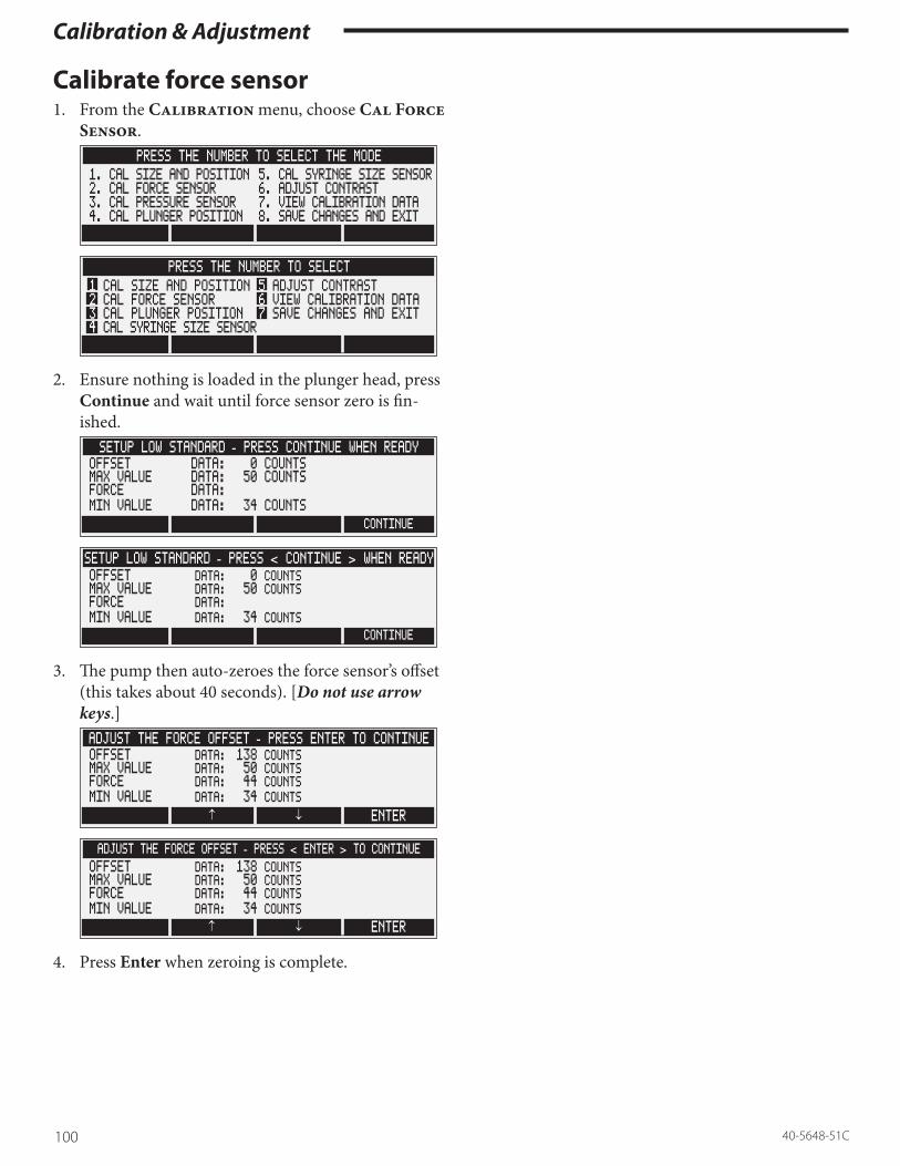
Calibration & Adjustment
100 40-5648-51C
Calibrate force sensor1. From the Calibration menu, choose Cal Force
Sensor.
1. CAL SIZE AND POSITION 5. CAL SYRINGE SIZE SENSOR2. CAL FORCE SENSOR 6. ADJUST CONTRAST3. CAL PRESSURE SENSOR 7. VIEW CALIBRATION DATA4. CAL PLUNGER POSITION 8. SAVE CHANGES AND EXIT
PRESS THE NUMBER TO SELECT THE MODE
PRESS THE NUMBER TO SELECT
1 CAL SIZE AND POSITION 5 ADJUST CONTRAST2 CAL FORCE SENSOR 6 VIEW CALIBRATION DATA3 CAL PLUNGER POSITION 7 SAVE CHANGES AND EXIT4 CAL SYRINGE SIZE SENSOR
2. Ensure nothing is loaded in the plunger head, press Continue and wait until force sensor zero is fin-ished.
OFFSET DATA: 0 COUNTS MAX VALUE DATA: 50 COUNTS FORCE DATA: MIN VALUE DATA: 34 COUNTS
SETUP LOW STANDARD - PRESS CONTINUE WHEN READY
CONTINUE
OFFSET DATA: 0 COUNTSMAX VALUE DATA: 50 COUNTSFORCE DATA: MIN VALUE DATA: 34 COUNTS
SETUP LOW STANDARD - PRESS < CONTINUE > WHEN READY
CONTINUE
3. The pump then auto-zeroes the force sensor’s offset (this takes about 40 seconds). [Do not use arrow keys.]
OFFSET DATA: 138 COUNTSMAX VALUE DATA: 50 COUNTSFORCE DATA: 44 COUNTSMIN VALUE DATA: 34 COUNTS
ADJUST THE FORCE OFFSET - PRESS ENTER TO CONTINUE
ENTER↓↑
OFFSET DATA: 138 COUNTSMAX VALUE DATA: 50 COUNTSFORCE DATA: 44 COUNTSMIN VALUE DATA: 34 COUNTS
ADJUST THE FORCE OFFSET - PRESS < ENTER > TO CONTINUE
ENTER↓↑
4. Press Enter when zeroing is complete.

Calibration & Adjustment
10140-5648-51C
5. Press the zero button on the force gauge. Load the force gauge under the barrel clamp resting flush on the case top. Ensure the flippers are below (closed) the force gage head, and use the thumbscrew to ad-just the gauge to 10 lbs. ±0.2, then press Continue. The force calibration is complete.
6. You return to the Calibration menu. You may calibrate another mode, choose Save Changes and Exit to exit calibration, or press â to return to the Biomed menu.

Calibration & Adjustment
102 40-5648-51C
Calibrate pressure sensor (future option)Do not use, this is a “future option” of the Medfusion® 3000 Series.
Calibrate plunger position1. From the Calibration menu, choose Cal
Plunger Position.
1. CAL SIZE AND POSITION 5. CAL SYRINGE SIZE SENSOR2. CAL FORCE SENSOR 6. ADJUST CONTRAST3. CAL PRESSURE SENSOR 7. VIEW CALIBRATION DATA4. CAL PLUNGER POSITION 8. SAVE CHANGES AND EXIT
PRESS THE NUMBER TO SELECT THE MODE
PRESS THE NUMBER TO SELECT
1 CAL SIZE AND POSITION 5 ADJUST CONTRAST2 CAL FORCE SENSOR 6 VIEW CALIBRATION DATA3 CAL PLUNGER POSITION 7 SAVE CHANGES AND EXIT4 CAL SYRINGE SIZE SENSOR
2. Load the small calibration slug into the barrel clamp. Squeeze the plunger lever to hold the flippers open, move the plunger head against the small slug, and press Continue to calibrate the low position.
MAX VALUE DATA: 200 COUNTSPLUNGER POS DATA: 151 COUNTSMIN VALUE DATA: 100 COUNTS
SETUP LOW STANDARD - PRESS CONTINUE WHEN READY
CONTINUE
MAX VALUE DATA: 200 COUNTSPLUNGERR POS DATA: 559 COUNTSMIN VALUE DATA: 100 COUNTS
SETUP LOW STANDARD - PRESS < CONTINUE > WHEN READY
CONTINUE
3. Load the large calibration slug into barrel clamp. Squeeze the plunger lever to hold the flippers open, move the plunger head against the large slug, and press Continue to calibrate high position.
MAX VALUE DATA: 175 COUNTSPLUNGER POS DATA: 125 COUNTSMIN VALUE DATA: 75 COUNTS
SETUP HIGH STANDARD - PRESS CONTINUE WHEN READY
CONTINUE
MAX VALUE DATA: 950 COUNTSPLUNGER POS DATA: 901 COUNTSMIN VALUE DATA: 850 COUNTS
SETUP HIGH STANDARD - PRESS < CONTINUE > WHEN READY
CONTINUE

Calibration & Adjustment
10340-5648-51C
4. You return to the Calibration menu. You may calibrate another mode, choose Save Changes and Exit to exit calibration, or press â to return to the Biomed menu.

Calibration & Adjustment
104 40-5648-51C
Calibrate syringe size sensor1. From the Calibration menu, choose Cal Sy-
ringe Size Sensor.
1. CAL SIZE AND POSITION 5. CAL SYRINGE SIZE SENSOR2. CAL FORCE SENSOR 6. ADJUST CONTRAST3. CAL PRESSURE SENSOR 7. VIEW CALIBRATION DATA4. CAL PLUNGER POSITION 8. SAVE CHANGES AND EXIT
PRESS THE NUMBER TO SELECT THE MODE
PRESS THE NUMBER TO SELECT
1 CAL SIZE AND POSITION 5 ADJUST CONTRAST2 CAL FORCE SENSOR 6 VIEW CALIBRATION DATA3 CAL PLUNGER POSITION 7 SAVE CHANGES AND EXIT4 CAL SYRINGE SIZE SENSOR
2. Load the small calibration slug into the barrel clamp. Keeping the barrel clamp perpendicular to the slug, move the clamp slightly back and forth to find the lowest size reading, then press Continue.
MAX VALUE DATA: 175 COUNTSSYRINGE SIZE DATA: 125 COUNTSMIN VALUE DATA: 75 COUNTS
SETUP LOW STANDARD - PRESS CONTINUE WHEN READY
CONTINUE
MAX VALUE DATA: 175 COUNTSSYRINGE SIZE DATA: 902 COUNTSMIN VALUE DATA: 75 COUNTS
SETUP LOW STANDARD - PRESS < CONTINUE > WHEN READY
CONTINUE
3. Load the large calibration slug into barrel clamp. Keeping the barrel clamp perpendicular to the slug, move the clamp slightly back and forth to find the lowest size reading, then press Continue to calibrate large size.
MAX VALUE DATA: 1024 COUNTSSYRINGE SIZE DATA: 975 COUNTSMIN VALUE DATA: 925 COUNTS
SETUP HIGH STANDARD - PRESS CONTINUE WHEN READY
CONTINUE
MAX VALUE DATA: 1024 COUNTSSYRINGE SIZE DATA: 125 COUNTSMIN VALUE DATA: 850 COUNTS
SETUP HIGH STANDARD - PRESS < CONTINUE > WHEN READY
CONTINUE
4. You return to the Calibration menu. You may calibrate another mode, choose Save Changes and Exit to exit calibration, or press â to return to the Biomed menu.
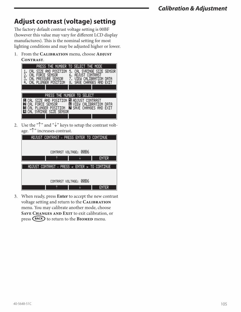
Calibration & Adjustment
10540-5648-51C
Adjust contrast (voltage) settingThe factory default contrast voltage setting is 00BF (however this value may vary for different LCD display manufactures). This is the nominal setting for most lighting conditions and may be adjusted higher or lower.
1. From the Calibration menu, choose Adjust Contrast.
1. CAL SIZE AND POSITION 5. CAL SYRINGE SIZE SENSOR2. CAL FORCE SENSOR 6. ADJUST CONTRAST3. CAL PRESSURE SENSOR 7. VIEW CALIBRATION DATA4. CAL PLUNGER POSITION 8. SAVE CHANGES AND EXIT
PRESS THE NUMBER TO SELECT THE MODE
PRESS THE NUMBER TO SELECT
1 CAL SIZE AND POSITION 5 ADJUST CONTRAST2 CAL FORCE SENSOR 6 VIEW CALIBRATION DATA3 CAL PLUNGER POSITION 7 SAVE CHANGES AND EXIT4 CAL SYRINGE SIZE SENSOR
2. Use the “↑” and “↓” keys to setup the contrast volt-age. “↑” increases contrast.
CONTRAST VOLTAGE: 00B6
ADJUST CONTRAST - PRESS ENTER TO CONTINUE
ENTER↓↑
CONTRAST VOLTAGE: 00B6
ADJUST CONTRAST - PRESS < ENTER > TO CONTINUE
ENTER↓↑
3. When ready, press Enter to accept the new contrast voltage setting and return to the Calibration menu. You may calibrate another mode, choose Save Changes and Exit to exit calibration, or press â to return to the Biomed menu.

Calibration & Adjustment
106 40-5648-51C
View calibration dataThis feature allows you to display the pump’s calibration data onscreen. This screen is generally used in factory service or for troubleshooting.
1. From the Calibration menu, choose View Cali-bration Data.
1. CAL SIZE AND POSITION 5. CAL SYRINGE SIZE SENSOR2. CAL FORCE SENSOR 6. ADJUST CONTRAST3. CAL PRESSURE SENSOR 7. VIEW CALIBRATION DATA4. CAL PLUNGER POSITION 8. SAVE CHANGES AND EXIT
PRESS THE NUMBER TO SELECT THE MODE
PRESS THE NUMBER TO SELECT
1 CAL SIZE AND POSITION 5 ADJUST CONTRAST2 CAL FORCE SENSOR 6 VIEW CALIBRATION DATA3 CAL PLUNGER POSITION 7 SAVE CHANGES AND EXIT4 CAL SYRINGE SIZE SENSOR
2. When ready, press Continue to return to the Cali-bration menu. You may calibrate another mode, choose Save Changes and Exit to exit calibra-tion, or press â to return to the Biomed menu.
FORCE 42 COUNTS 475 COUNTS 0PLUNGER POS 151 COUNTS 901 COUNTSPRESSURE 0 COUNTS 0 COUNTS
SYRINGE SIZE 125 COUNTS 975 COUNTS
PRESS CONTINUE WHEN READY
CONTINUE
FORCE 42 COUNTS 475 COUNTS 138PLUNGER POS 151 COUNTS 901 COUNTSSYRINGE SIZE 125 COUNTS 975 COUNTS
PRESS < CONTINUE > WHEN READY
CONTINUE
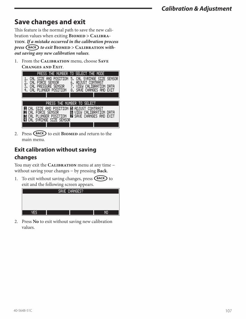
Calibration & Adjustment
10740-5648-51C
Save changes and exitThis feature is the normal path to save the new cali-bration values when exiting Biomed > Calibra-tion. If a mistake occurred in the calibration process press â to exit Biomed > Calibration with-out saving any new calibration values.
1. From the Calibration menu, choose Save Changes and Exit.
1. CAL SIZE AND POSITION 5. CAL SYRINGE SIZE SENSOR2. CAL FORCE SENSOR 6. ADJUST CONTRAST3. CAL PRESSURE SENSOR 7. VIEW CALIBRATION DATA4. CAL PLUNGER POSITION 8. SAVE CHANGES AND EXIT
PRESS THE NUMBER TO SELECT THE MODE
PRESS THE NUMBER TO SELECT
1 CAL SIZE AND POSITION 5 ADJUST CONTRAST2 CAL FORCE SENSOR 6 VIEW CALIBRATION DATA3 CAL PLUNGER POSITION 7 SAVE CHANGES AND EXIT4 CAL SYRINGE SIZE SENSOR
2. Press â to exit Biomed and return to the main menu.
Exit calibration without saving changesYou may exit the Calibration menu at any time − without saving your changes − by pressing Back.
1. To exit without saving changes, press â to exit and the following screen appears.
SAVE CHANGES?
YES NO
2. Press No to exit without saving new calibration values.

Calibration & Adjustment
108 40-5648-51C
Retest guidelinesThe following are minimum guidelines for re-calibra-tion and re-testing after repair.
Repair Type From Biomed > Calibration, perform:
From Periodic Maintenance, perform:
Pump Opened None Quick Check-outRepair drive-train
Replace motor None Complete Mandatory Annual Mainte-nance Testing
Replace clutches, square rod, lead-screw, or plunger cable
Recalibrate position & size Complete Mandatory Annual Mainte-nance Testing
Repair sensorsReplace ear clip or ear
clip sensorRecalibrate size Quick Check-out & Calibration Verifi-
cationReplace barrel clamp
assy or size pot.Recalibrate size Quick Check-out & Calibration Verifi-
cationReplace force sensor Recalibrate force Quick Check-out & Calibration Verifi-
cationReplace position pot Recalibrate position & size Quick Check-out & Calibration Verifi-
cation & Plunger Travel TestRepair electronics
Replace speaker None Quick Check-outReplace interconnect
cableNone Quick Check-out
Replace AC supply None Quick Check-outReplace battery None Quick Check-out & after AC charging
run Power-up TestsReplace interconnect
boardNone Quick Check-out
Replace keypad, display or backlight
None Quick Check-out & Calibration Verifi-cation
Replace main board/component
Recalibrate all sensors Complete Mandatory Annual Mainte-nance Testing
Replace plunger board/component
Recalibrate force Quick Check-out & Calibration Verifi-cation
Software UpdatesReprogramming See update instructions See update instructions
Repair case or case parts
Replace case bottom None Quick Check-out

Calibration & Adjustment
10940-5648-51C
Replace case top Recalibrate all sensors Complete Mandatory Annual Mainte-nance Testing
Replace case handle Recalibrate position & size Quick Check-out & Calibration Verifi-cation
Replace plunger head, or flippers
Recalibrate force Quick Check-out & Calibration Verifi-cation
Replace IR lens None Quick Check-outReplace plunger lever None Quick Check-outReplace pump labels None Quick Check-outReplace feet None Quick Check-outReplace tubing holders Recalibrate size Quick Check-out & Calibration Verifi-
cation

Calibration & Adjustment
110 40-5648-51C

Schematics & PCB Assemblies
11140-5648-51C
System layoutSY
RIN
GE
SIZE
DET
ECTO
R
SYRI
NG
E EA
R D
ETEC
TOR
KEYPAD INTERFACE
SIZE
_SN
SR_E
X
SYRI
NG
E_SI
ZE
J41 2 3 4
J21 2 3 4
SYRI
NG
E_EA
R_SN
SR_ E
NBL
SYRI
NG
E_EA
R_D
ETEC
T
LOG
IC_ S
PLY
(FIL
TERE
D)
MA
IN_P
CB
J10
1 2 3 4 5 6 7 8 9 10 11 12 13 14 15 16 17 18 19
20 21 22 23 24
BACK
-UP
POW
ER S
OU
RCE
BACK
-UP
BUZZ
ER
LED_TAIL KEY_MATRIX_TAIL
KEYP
AD
_ PCE
LL_ L
EDKE
YPA
D_ I
NFU
SIO
N_ L
EDL
KEYP
AD
_ IN
FUSI
ON
_ LED
MKE
YPA
D_ I
NFU
SIO
N_ L
EDR
KEYP
AD
_ CAU
TIO
N_ L
EDKE
YPA
D_ W
ARN
ING
_ LED
KEYP
AD
_ BAT
TERY
_ LED
KEYP
AD
_ AC_
LED
KEYP
AD
_ LO
CKO
UT_
LED
KEYP
AD
_ CO
L5KE
YPA
D_ C
OL4
KEYP
AD
_ CO
L3KE
YPA
D_ R
OW
3KE
YPA
D_ R
OW
2KE
YPA
D_ R
OW
1KE
YPA
D_ R
OW
0
KEYP
AD
_ CO
L2KE
YPA
D_ C
OL1
KEYP
AD
_ CO
L0
KEYP
AD
_ PW
RSW
X
PLU
NG
ER
J11
FORC
E_EX
CFO
RCE_
PREA
MP_
OU
TPL
UN
GER
_ SN
SR1_
OU
TPL
UN
GER
_ SN
SR2_
OU
TPL
UN
GER
_ SN
SRS_
ENBL
FORC
E_SY
S_TE
STVN
EG_ S
PLY
FORC
E_PR
EAM
P_O
SAD
J
LOG
IC_ S
PLY
(FIL
TERE
D)
121110987654321
J12
2 3 4 5 6 7 9 10 11 12 21 3 4 5 6 7 8 9 10 11 12
DIS
PLAY
2019181716151413121110
9876
45
321
LOGIC_SPLY (FILTERED)LCD_CONTRAST
EVALID_WRITEBFRD_EVALID_READ
LCD_CSLCD_COMMAND
(NOT USED)LCD_RESET
(NOT USED)
B_DATE0B_DATE1B_DATE2B_DATE3B_DATE4B_DATE5B_DATE6B_DATE7
2019181716151413121110
9876
45
321
J8
87654321SE
T_IN
_ SN
SR_ D
RVSE
T_IN
_ DET
ECT
PRES
SURE
_ SN
SR_ O
UTL
PRES
SURE
_ SN
SR_ O
UTH
PRES
SURE
_ SN
SR_ E
XH
SET_
IN_ S
ENSO
R
POW
ERTR
AN
SDU
CER
J9
CLA
SS II
AC
INPU
T
12V INTERNAL POWER SUPPLY
6ND
12V
12
J3J4
J1
Pack
Batt
ery
123456789
10
CHARGE_DETECT
CHARGEBATTERY_POS_LEAD
BATTERY_DATA
VLOW_BATTERY
J7
TRAV
EL_ S
NSR
_ OU
T
TRAV
EL_ S
NSR
_ EXC
4321PO
SITI
ON
SEN
SOR
J3
4321M
TR_ D
RV_ P
HA
MTR
_ DRV
_ PH
AM
TR_ D
RV_ P
HB
MTR
_ DRV
_ PH
BST
EPM
OTO
R
FILT
_ 5V
IR_ R
CV_ D
ATA
IR_ X
MT_
DAT
A
UN
SWX_
CD_ P
OW
ER
EXTE
RNL_
PWR_
DET
ECT
VLO
W_ B
ATTE
RYBA
TTER
Y_D
ATA
AC_
PWR_
DET
ECT
CHA
RGE_
DET
ECT
BACK
UP_
CHA
RGE_
SRC
SPEA
KER_
RET
SPEA
KER_
DRI
VE
POW
ER_ F
NRI
4321 5 6 7 8 9 10 11 12 13 14 15 16 17 18 19 20 21 22 23 24 25 26
4321 5 6 7 8 9 10 11 12 13 14 15 16 17 18 19 20 21 22 23 24 25 26
INTE
RCO
NN
ECT
PCB
OPT
ICA
L CO
MM
UN
ICAT
ION
INTE
RFA
CE
EXTE
RNA
L D
C SU
PPLY XM
TR
RCVR
J2
SPEA
KER
321
21

Schematics & PCB Assemblies
112 40-5648-51C
Main board schematicsThe following are the main board schematics if the Medfusion® 3000 Series pump.
Main board / logic kernel

Schematics & PCB Assemblies
11340-5648-51C
Main Board / Logic Kernel -- Continued

Schematics & PCB Assemblies
114 40-5648-51C
Main Board / Logic Kernel -- Continued
ascerted

Schematics & PCB Assemblies
11540-5648-51C
Main Board / Logic Kernel -- Continued

Schematics & PCB Assemblies
116 40-5648-51C
Main Board / Power Control Logic Core

Schematics & PCB Assemblies
11740-5648-51C
Main Board / Power Control Logic Core -- Continued

Schematics & PCB Assemblies
118 40-5648-51C
Main Board / DC-DC Converter

Schematics & PCB Assemblies
11940-5648-51C
Main Board / DC-DC Converter -- Continued

Schematics & PCB Assemblies
120 40-5648-51C
Main Board / Keypad Interface

Schematics & PCB Assemblies
12140-5648-51C
Main Board / Keypad Interface -- Continued
KEYP
AD_L
OCKO
UT_L
ED {1
0}

Schematics & PCB Assemblies
122 40-5648-51C
Main Board / Keypad Interface - Continued
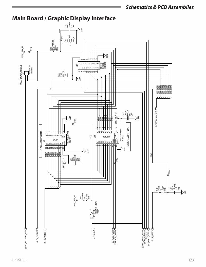
Schematics & PCB Assemblies
12340-5648-51C
Main Board / Graphic Display Interface

Schematics & PCB Assemblies
124 40-5648-51C
Main Board / Motor Drive

Schematics & PCB Assemblies
12540-5648-51C
Main Board / Syringe Sensing

Schematics & PCB Assemblies
126 40-5648-51C
Main Board / Position Sensing

Schematics & PCB Assemblies
12740-5648-51C
Main Board / Force Sensing

Schematics & PCB Assemblies
128 40-5648-51C
Main Board / Pressure Sensing

Schematics & PCB Assemblies
12940-5648-51C
Main Board / Speaker Drive
TP36
3
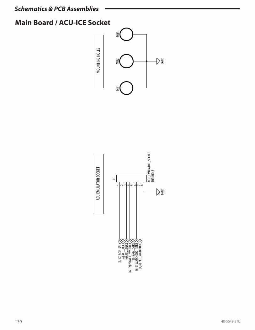
Schematics & PCB Assemblies
130 40-5648-51C
Main Board / ACU-ICE Socket

Schematics & PCB Assemblies
13140-5648-51C
Main Board Assembly Drawing – Top Side
1
18
Date Code/Serial # Assembly Rev.R77
R85
C35
C17
J4
U30
J21
C68+
U17
C6 U24
U22
C11
J12
+U
46
U5
U11
U19
+
C72C30 C27
R63 R96
1 2
19 20
1
+
+
+
+
+
+
+
+ ++
+ +
+
X2 J5
C21 R1 C12R89
R90
R88R83
C94
U38 Q18
C42
C92
C10C152
C123
U32
U6 U4 U
3
C125C124
C66
X3
U39
D8
U7
U31
C15
R103
U4
U2
U8
J9
C14C78
X1
C51
FB8 C91C7
C8 R9
C13
R45
R46
C102U
21
C26
C98
R148
Q2
Q41
L2
C44
U12 L1
C70
R36
U28
U25
U42
C38
+
U36
C60
C37
U33
C86
J11
FB7
C58
R113 C9 U15
U13U
44
Q45
Q22
Q16
Q21
C53
+
XD1
D1
C97
C4
C59
FB2
R20
R182
R181
R152
R55
R56
C41
FB12R67
FB6R146R133
FB5
C99
R76
R80
R68
C25
C16
C24
C112
C71
C68
C116
C89
U20
C49
U34L3
C45
C118
D23
U18
C117
R16
R18C121
R140
R131
R159
U1
C19R2J1
3
C23
R84
R3R1
44
R143R1
53
R166
R158
C128
C131
C132
C134
C150
C148
C146
C81
U9
U14
R50
C127
R186
R185
C77
C79
J8
C48 Q
38
U23
J10C111
R95
C36
R137
C96
J61
U26
U35
U40
C57
C106 C110R104
C114
J3
1
1 C95J7

Schematics & PCB Assemblies
132 40-5648-51C
Main Board Assembly Drawing – Bottom Side
R86
R34
C5 R43
R174
R167
R33C22
C88
R23C3
R22
R102R70
C20
R7
R11
C107
R8
R12
R29
R25
R21
R17
C40
C34
FB1C18
R145
C43
R78
FB3
C87
R98
R105
C108
C120
FB11
R175
C151
C126
R69
C90
R27
R57
C82R44
R71
R64
R54
R40
R39
C74C33
C154R66
C153
FB13
C160R122
R65
R41
R42
R62
R60
R59
R72
R73
C104
R119
C103
R117
R118
C83
C109
R125
R82
R51
R58R30
FB4
C39
R108
R111
R110
R162
C56
R109
C115
R161C159
R168
C1
R87
R32 FB10
C122
R129
R178
R128
R179
R172
R171
R127
R177
R134
R135
R170
C93 C62
R74
C85
R48R75
R76
FB14 R149
C75
R151
R147
C76C80
R150
C67C54
R28R35
R94
C161
R93
R26
C28R92C55
R13R10
C46R132C50
C52 C147
R154
R157
R160
R139
C149 C133
R138R53
R173
C119 C2U10
C84R81R49
R165
R120
R100
FB15
TVS15
R24R112
R38
R37
C73
C141
C140
C139
TVS16
C135
R124
C138
R187
R123
R61
C143
C145
C142
C136
C144
C137
R99
C101
R91
R101C100
R116
R6
C29
R5
R164R136
R97
C105
R115
C47
R142
R15
R14
C31
R155
R126
C61
C113
R141
C63
R19
C64
C65 R156
R107
R121 R169
C130
C129
+
+
++
+
C162
U16
D10
D9
D7
U43
U45
C23
R52
Q19
D12
Q20
D11
Q11
D16
Q13
Q14
Q15
Q29
D3D2
D13
R4
R31
Q1
Q24
Q12
Q17
Q4
C157
C155
C156
U27
Q8
D15
D14
R47
Q26
D5
D4
D20
Q40
Q42
Q30
Q27
Q37
Q35
D6
Q34
D4
Q33
Q36
Q3
D6
U37
U29
R106
C163
D22
Q28
D19
Q10 Q
5
C158
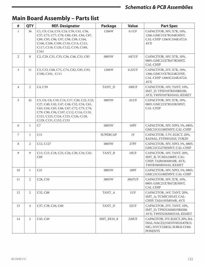
Schematics & PCB Assemblies
13340-5648-51C
Main Board Assembly – Parts list # QTY REF. Designator Package Value Part Spec1 36 C1, C9, C16, C19, C24, C39, C41, C56,
C57, C73, C77, C78, C80, C81, C84, C87, C89, C95, C96, C97, C98, C99, C104, C106, C108, C109, C110, C114, C115, C117, C118, C120, C122, C130, C160, C161
1206W 0.1UF CAPACITOR, 50V, X7R, 10%, 1206; GMC31X7R104K50NT, CAL-CHIP 12065C104KAT2A AVX
2 8 C2, C29, C31, C35, C36, C46, C55, C83 0805W .047UF CAPACITOR, 50V, X7R, 10%, 0805; GMC21X7R473K50NT, CAL-CHIP
3 11 C3, C33, C68, C71, C74, C82, C85, C93, C100, C101, C111
1206W 0.22UF CAPACITOR, 25V, X7R, 10%, 1206; GMC31X7R224K25NE, CAL-CHIP 12063C224KAT2A AVX
4 2 C4, C59 TANT_D 100UF CAPACITOR, 10V, TANT, 10%, SMT_D; TPSD107K010R0100, AVX; T495D107K010AS, KEMET
5 42 C5, C6, C8, C10, C14, C17, C20, C22, C23, C27, C40, C42, C47, C48, C52, C54, C61, C63, C64, C65, C66, C67, C72, C75, C76, C79, C90, C94, C107, C112, C116, C119, C121, C123, C124, C125, C126, C128, C129, C151, C152, C153
0805W .01UF CAPACITOR, 50V, X7R, 10%, 0805; GMC21X7R103K50NT, CAL-CHIP
6 1 C7 0805W 10PF CAPACITOR, 50V, NPO, 5%, 0805; GMC21CG100J50NT, CAL-CHIP
7 1 C11 SUPERCAP 1F CAPACITOR, 5.5V, ELECT, 20%, RADIAL; FYD0H105Z; TOKIN
8 2 C12, C127 0805W 27PF CAPACITOR, 50V, NPO, 5%, 0805; GMC21CG270J50NT, CAL-CHIP
9 9 C13, C15, C18, C25, C26, C30, C34, C43, C69
TANT_B 10UF CAPACITOR, 10V, TANT, 20%, SMT_B; TCMIA106BT, CAL-CHIP; TAJB106M010R, AVX; T491B106M010AS, KEMET
10 1 C21 0805W 18PF CAPACITOR, 50V, NPO, 5%, 0805; GMC21CG180J50NT, CAL-CHIP
11 2 C28, C50 0805W .0047UF CAPACITOR, 50V, X7R, 10%, 0805; GMC21X7R472K50NT, CAL-CHIP
12 2 C32, C88 TANT_A 1UF CAPACITOR, 16V, TANT, 20%, SMT_A; TCMIC105AT, CAL-CHIP; TAJA105M016R, AVX
13 4 C37, C38, C44, C60 TANT_D 22UF CAPACITOR, 25V, TANT, 10%, SMT_D; TPSD226M025R0200, AVX; T495D226M025AS, KEMET
14 2 C45, C49 SMT_8X10_8 220UF CAPACITOR, 35V, ELECT, 20%, RA-DIAL; NACZ221M35V8X10.8TR13, NIC; 35VCV220GX, SURGE COM-PONENTS

Schematics & PCB Assemblies
134 40-5648-51C
# QTY REF. Designator Package Value Part Spec15 2 C51, C53 TANT_D 100UF CAPACITOR, 10V, TANT, 20%,
SMT_D; TCMIA107DT, CAL-CHIP; TAJD107M010R, AVX; T491D107M010AS, KEMET
16 13 C58, C62, C86, C103, C105, C113, C155, C156, C157, C158, C159, C162, C163
0805W 1000PF CAPACITOR, 50V, NPO, 5%, 0805; GMC21CG102J50NT, CAL-CHIP
17 1 C70 CAP_200MIL 1UF CERAMIC, 100V, X7R, 10%, LEADED; SR401C105KAA, AVX; RPE114X7R105K100V, MURATA ERIE
18 2 C91, C92 0805W 100PF CAPACITOR, 50V, NPO, 5%, 0805; GMC21CG101J50NT, CALCHIP
19 1 C102 SMT_10X10_8 330UF CAPACITOR, 35V, ELECT, 20%, RADIAL; NACZ331M35V10X10.8TRHIL, NIC
20 21 C131, C132, C133, C134, C135, C136, C137, C138, C139, C140, C141, C142, C143, C144, C145, C146, C147, C148, C149, C150, C154
0805W 1000PF CAPACITOR, 50V, NPO, 5%, 0805;GMC21CG102J50NT, CAL-CHIP
21 2 D1,D23 SMC CMSH3-60, CENTRAL SEMI; 30BQ060, INTERN. RECTIFIER
22 18 D2,D3,D4,D5,D6, D7,D8,D9,D10,D11, D12,D13,D14,D15, D16,D19,D20,D22
SOT23 MMBD914LT1, MOTOROLA
23 13 FB1,FB2,FB3,FB4, FB5,FB6,FB7, FB10,FB11,FB12, FB13,FB14,FB15
0805W BLM21A102SPT, MURATA ERIE
24 1 FB8 1206W BLM31P500SPT, MURATA ERIE25 1 GL1 GNDLNK N/A26 2 J2,J6 4P_059SMTH-
DRB4B-ZR-SM3-TF, JST
27 1 J3 4P_079SMTH-DR
B4B-PH-SM3-TB, JST
28 1 J4 4P_050THHDR 104071-7, AMP29 2 J5,J13 2P_THJMPR HTSW-102-06-T-S, SAMTEC30 1 J7 2PINTH_
TERMBLK30.870.002 OR 930-T-DS-02, WECO
31 1 J8 8P_050RATH-HDR
53048-0810 molex
32 1 J9 26P_079THDRHDR
1306-26-S-02, SINGATRON
33 1 J10 24P_050RATH-DRHDR
1-104069-2, AMP
34 1 J11 11P_059SMTH-DR
B11B-ZR-SM3-TF, JST
35 1 J12 20P_100THH-DR
609-2027, THOMAS & BETTS
36 2 L1, L2 SMT_POT-CORE
DT3316P-473, COILCRAFT
37 1 L3 SMT_POT-CORE
DT3316P-333, COILCRAFT

Schematics & PCB Assemblies
13540-5648-51C
# QTY REF. Designator Package Value Part Spec38 13 Q1,Q3,Q11,Q12, Q13,Q14,Q21,Q24,
Q28,Q29,Q30,Q38, Q42SOT23 2N7002T1, SILICONIX (TEMIC);
CENTRAL SEMICONDUCTOR39 1 Q2 SO8 MMSF3P02HDR2G, On Semi40 7 Q4,Q6,Q8,Q10,Q16, Q19,Q41 SOT23 MMBT2222ALT1, MOTOROLA41 16 Q5,Q7,Q15,Q17, Q18,Q20,Q22,Q26,
Q27,Q33,Q34,Q35, Q36,Q37,Q40,Q45SOT23 TP0610T, Supertex; TP0610T,
Vishay SILICONIX (TEMIC) [obsolete]
42 1 R1 1206W 10MOHM RESISTOR, 1/8W, TCR=400PPM, 5%, 1206; RM12J106CT, CAL-CHIP
43 1 R2 1206W 2.70OHM RESISTOR, 1/8W, TCR=400PPM, 5%, 1206; RM12J2R7CT, CAL-CHIP; IRC WCR1206
44 4 R3, R16, R17, R125 0805W 2.0KOHM RESISTOR, 1/10W, TCR=100PPM, 1%, 0805; RM10F2001CT, CAL-CHIP
45 2 R4, R18 1206W 24OHM RESISTOR, 1/8W, TCR=400PPM, 5%, 1206; RM12J240CT, CAL-CHIP; ERJ-8GEYJ240V, PANA-SONIC
46 12 R5, R8, R14, R19, R28, R37, R87, R162, R168, R182, R185, R186
0805W 1.0KOHM RESISTOR, 1/10W, TCR=100PPM, 1%, 0805; RM10F1001CT, CAL-CHIP
47 3 R6, R15, R20 2010 0.5OHM RESISTOR, 1/2W, TCR=100PPM, 1%, 2010; WSL2010R500F, DALE; LR201001R500F, IRC
48 13 R7, R11, R13, R21, R25, R26, R29, R46, R105, R106, R120, R144,R164
0805W 4.99KOHM RESISTOR, 1/10W, TCR=100PPM, 1%, 0805; RM10F4991CT, CAL-CHIP
49 24 R27, R30, R31, R41, R42, R61, R62, R78, R92, R96, R97, R103, R118, R123, R124, R156, R170, R171, R172, R177, R178, R179, R187
0805W 10KOHM RESISTOR, 1/10W, TCR=200PPM, 5%, 0805; RM10J103CT, CAL-CHIP
50 2 R10, R40 0805W 64.9KOHM RESISTOR, 1/10W, TCR=100PPM, 1%, 0805; RM10F6492CT, CAL-CHIP
51 8 R12, R43, R75, R93, R115, R141, R143, R149
0805W 15.0KOHM RESISTOR, 1/10W, TCR=100PPM, 1%, 0805; RM10F1502CT, CAL-CHIP
52 14 R22, R32, R36, R39, R54, R57, R58, R82, R83, R84, R94, R133, R146, R173
0805W 200KOHM RESISTOR, 1/10W, TCR=200PPM, 5%, 0805; RM10J204CT, CAL-CHIP
53 1 R23 0805W 1MOHM RESISTOR, 1/10W, TCR=200PPM, 5%, 0805; RM10J105CT, CAL-CHIP
54 2 R24, R155 0805W 150.0KOHM RESISTOR, 1/10W, TCR=100PPM, 1%, 0805; RM10F1503CT, CAL-CHIP
55 4 R33, R34, R167, R174 0805W 100OHM RESISTOR, 1/10W, TCR=200PPM, 5%, 0805; RM10J101CT, CAL-CHIP

Schematics & PCB Assemblies
136 40-5648-51C
# QTY REF. Designator Package Value Part Spec56 7 R35, R38, R49, R77, R95, R98, R166 0805W 220OHM RESISTOR, 1/10W, TCR=200PPM,
5%, 0805; RM10J221CT, CAL-CHIP
57 7 R44, R104, R126, R140, R145,R169 0805W 20.0KOHM RESISTOR, 1/10W, TCR=100PPM, 1%, 0805; RM10F2002CT, CAL-CHIP
58 26 R45, R52, R59, R60, R63, R64, R67, R68, R70, R71, R72, R73, R79, R80, R86, R102, R112, R122, R127, R128, R129, R134, R135, R175
0805W 1KOHM RESISTOR, 1/10W, TCR=200PPM, 5%, 0805; RM10J102CT, CAL-CHIP
59 12 R47, R55, R66, R74, R85, R99, R101, R108, R137, R152, R153
0805W 120KOHM RESISTOR, 1/10W, TCR=200PPM, 5%, 0805; RM10J124CT, CAL-CHIP
60 4 R48, R91, R147, R151 0805W 10.0KOHM RESISTOR, 1/10W, TCR=100PPM, 1%, 0805; RM10F1002CT, CAL-CHIP
61 1 R50 0805W 649.0OHM RESISTOR, 1/10W, TCR=100PPM, 1%, 0805; RM10F6490CT, CAL-CHIP
62 2 R51, R109 0805W 2.2MOHM RESISTOR, 1/10W, TCR=400PPM, 5%, 0805; RM10J225CT, CAL-CHIP
63 8 R53, R107, R138, R139, R154, R157, R158, R159
0805W 160OHM RESISTOR, 1/10W, TCR=200PPM, 5%, 0805; RM10J161CT, CAL-CHIP
64 5 R56, R65, R69, R117, R148 0805W 47KOHM RESISTOR, 1/10W, TCR=200PPM, 5%, 0805; RM10J473CT, CAL-CHIP
65 6 R76, R116, R142, R161, R181, R136 0805W 40.2KOHM RESISTOR, 1/10W, TCR=100PPM, 1%, 0805; RM10F4022CT, CAL-CHIP
66 2 R81, R100 0805W 825.0OHM RESISTOR, 1/10W, TCR=100PPM, 1%, 0805; RM10F8250CT, CAL-CHIP
67 2 R110, R132 0805W 27KOHM RESISTOR, 1/10W, TCR=200PPM, 5%, 0805; RM10J273CT, CAL-CHIP
68 1 R111 0805W 392.0KOHM RESISTOR, 1/10W, TCR=100PPM, 1%, 0805; RM10F3923CT, CAL-CHIP
69 1 R113 0805W 51OHM RESISTOR, 1/10W, TCR=200PPM, 5%, 0805; RM10J510CT, CAL-CHIP
70 3 R119, R131, R165 0805W 49.9KOHM RESISTOR, 1/10W, TCR=100PPM, 1%, 0805; RM10F4992CT, CAL-CHIP
71 1 R150 0805W 24.9KOHM RESISTOR, 1/10W, TCR=100PPM, 1%, 0805; RM10F2492CT, CAL-CHIP
72 1 R160 0805W 475.0OHM RESISTOR, 1/10W, TCR=100PPM, 1%, 0805; RM10F4750CT, CAL-CHIP

Schematics & PCB Assemblies
13740-5648-51C
# QTY REF. Designator Package Value Part Spec73 412 TP1, TP2, TP3, TP4, TP5 TESTPOINT N/A74 2 TVS15, TVS16 0805W VC080505A150, AVX75 5 U1,U14,U23, U28, U42 TSSOP8 OP296HRU, ANALOG DEVICES76 2 U2, U4 SO8 AT25256AN-10SU-2.7, Atmel;
M95256-WMN6TP ST Microelec-tronics; M95256-WMN6-TGST Microelectronics
77 2 U3, U33 44PLCC CS82C55A, HARRIS/INTERSIL; MSM82C55A-2VJS, OKI
78 1 U5 TSSOP14 SN74AHC00PWR, TEXAS INSTR79 2 U6, U41 TSSOP20 SN74AHC541PWR, TEXAS
INSTR80 1 U7 SO8 LM2936M-5.0; NATIONAL SEMI81 1 U8 SSOP8 RS5C316B, RICOH82 1 U9 SO8 AD623AR, ANALOG DEVICES83 3 U10, U27, U30 SOT23-5 LMC7111BIM5, NATION-
AL SEMICONDUCTOR; MIC7111BM5, MICREL
84 1 U11 TSSOP14 SN74ACH125PWR, TEXAS INSTR
85 2 U12, U34 SO8 LT1372CS8, LINEAR TECH
86 1 U13 SO16 TLV1544CD, TEXAS INSTR
87 1 U16 TO236AB LM4040DIM3-4.1, NATIONAL SEMICONDUCTOR, MICREL SEMICONDUCTOR
88 1 U17 SOP28 TC55257DFL85L, TOSHIBA; TC55257DFL70L, TOSHIBA; M5M5256DFP-70LL, Mitsubishi; LH52256CN-70LL, Sharp
89 2 U18, U37 SOT23-5 LMC7211AIM5, NATION-AL SEMICONDUCTOR; MIC7211BM5, MICREL
90 1 U19 84PLCC_SKT 68HC11K1CFN4 OR 68HC11K-0CFN4, MOTOROLA
91 1 U20 SO8 MAX522CSA, MAXIM
92 1 U21 SOT223 LT1121CST-5, LINEAR TECH
93 1 U22 32TSOP AT29C040A-12TU Atmel
94 1 U24 TSSOP16 SN74AHC138PWR, TEXAS INSTR
95 1 U25 SO14 MC74HC4066AD, OnSemi; SN-74HC4066PW, TEXAS INSTR
96 2 U26, U35 SO16W A3953SLB, ALLEGRO
97 1 U29 SO6 SFH9201-2/3, Osram (Smiths Med-ical catalog number G6000157)
98 1 U31 SO8 LM386M-1, NATIONAL SEMI-CONDUCTOR; NJM386BM, NEW JAPAN RADIO
99 1 U32 TSSOP20 SN74AHC573PWR, TEXAS INSTR

Schematics & PCB Assemblies
138 40-5648-51C
# QTY REF. Designator Package Value Part Spec100 1 U36 SSO8 MAX865EUA, MAXIM
101 1 U38 SOT23 MAX6326UR31-T, MAXIM
102 1 U39 SO8W PIC12C50804/SM, MICROCHIP (programmed)
103 1 U40 SO8 LM393M, NATIONAL SEMI; LM393D, TEXAS INSTR
104 1 U43 SOT23 MAX809LEURT, MAXIM; ADM-809LART, ANALOG DEVICES
105 1 U44 TO236AB LM4040BIM3-4.1, NATIONAL SEMI
106 1 U45 SOT23-5 SN74AHC1G14DBVR, TEXAS INSTR
107 1 U46 SO16 MC74HC174AD, MOTOROLA; SN74HC174D, TEXAS INSTR.; 74HC174D, PHILIPS; M74H-C174M1R, SGS
108 1 X1 SMT_32KHZX-TAL
32KHZ MC306-32.768KA-E3, EP-SON; ECPSM29T-32.768KTR, ECLIPTEK; SX1555-32.768KT/R, MTRON
109 1 X2 SMT_16MHZX-TAL
16MHZ EC2SM 16.000MHZ T&R, ECLIPTEK
110 1 X3 SMT_455KHZ- XTAL
455KHZ CSBFB455KJ58-R1, MURATA ERIE
111 1 XD1 TH_BUZZER HMB-06, STAR MICRONIX (Smiths Medical catalog number 6940000100)
112 1 PCB N/A RAW, PRINTED CIRCUIT BOARD
113 1 PRESS_IN NUT N/A PRESS-IN NUT , 2-56 THREAD, 0.219” DIA., STAINLESS STEEL; P/N 4860, KEYSTONE; KFS2-256, PEM
114 1 U15 TSSOP8 OP727ARU Analog Devices
115 1 R121 0805W 1.37KOHM CRCW08051371F50 Vishay, RK-73GC2ATTD1371F KOA
116 2 R9, R89 0805W 4.7KOHM RESISTOR, 1/10W, TCR=200PPM, 5%, 0805; CRCW0805472J, Vishay Dale; RK73B2ATTD472J KOA Speer
117 1 R88 0805W 130OHM RESISTOR, 1/10W, TCR=200PPM, 5%, 0805; CRCW0805131JRT6, Vishay Dale; RK73B2ATTD131J KOA Speer
118 1 R90 0805W 18KOHM RESISTOR, 1/10W, TCR=200PPM, 5%, 0805; CRCW0805183J, Vishay Dale; RK73B2ATTD183J KOA Speer

Schematics & PCB Assemblies
13940-5648-51C
Plunger Board SchematicPlunger Board / Force Preamplifier

Schematics & PCB Assemblies
140 40-5648-51C
Plunger Board / Flipper Sensor
LGN
D
LGN
D
LGN
D
LGN
D
LGN
D
LGN
D
LGN
D
LGN
D
LGN
D
LGN
D
LGN
D
LGN
D
LGN
D
LOG
IC_ S
PLY
5_VD
C
LOG
IC_ S
PLY
5_VD
C
VNEG
_ SPL
Y
FORC
E_SN
SR_ E
X
FORC
E_PR
EAM
P_O
UT
PLU
NG
ER_ S
NSR
2_O
UT
PLU
NG
ER_ S
NSR
1_O
UT
PLU
NG
ER_ S
NSR
S_EN
BL
FORC
E_SN
SR_ T
EST
FORC
E_PR
EAM
P_O
SAD
J
C10
470P
F2%
J2FB
2
FB3
FB4
FB5
FB6
FB1
C14
C12
C6
C9
C13
C5
C7
C11
Q1
R9
R7
R6
U3
R8
U2
C8
1 2 3 4 5 6 7 8 9 10 11
12
470P
F2%
470P
F2%
470P
F2%
470P
F2%1U 16
V
470P
F2%
470P
F2%
470P
F2%
2.0K
OH
M
2N22
22A
100O
HM
1 4
2 3
1 4
2 3
0.1U
F
24.9
KOH
M
24.9
KOH
M
+

Schematics & PCB Assemblies
14140-5648-51C
Plunger Board Assembly Drawing Top Side:
FB1C7
J2
U1
J1C1R5
C3Q2 R4
R3U3
Q1R9
U2
C10
PH2
PH1
R2
+
Bottom Side:
FB5FB6
FB4C13
C12C4
FB2C2
R1C11 C5
R10 C14C9
R6C8 C6
R8
SERIAL LABEL
R7

Schematics & PCB Assemblies
142 40-5648-51C
Plunger Board Assembly – Parts list # QTY REF. Designator Package Value Part Spec1 12 C1, C2, C3, C4, C5, C6, C9, C10, C11,
C12, C13, C140603 470PF CERAMIC, 50V, NP0, 2%, 0603;
GMC10CG471G50NT, CAL-CHIP2 1 C7 TANT_A 1U CAPACITOR, 16V, TANT, 20%,
SMT_A; TCMIC105AT, CAL-CHIP; TAJA105M016R, AVX
3 1 C8 1206 0.1UF CAPACITOR, 50V, X7R, 10%, 1206; GMC31X7R104K50NT, CAL-CHIP 12065C104KAT2A; AVX
4 5 FB1, FB2, FB4, FB5, FB6 0603 BLM11A102SGPT, MURATA ERIE5 1 J1 4PINSMTHDR_
WBOSS90814-0004, MOLEX
6 1 J2 11PIN_1_5MMSMTHDR
B11B-ZR-SM3-TF, JST
7 1 Q1 SOT23 MMBT2222ALT1, ON SEMICON-DUCTOR; CMPT 2222ATR or TR13 CENTRAL SEMICONDUC-TOR
8 1 Q2 SOT23 TP0610T, Supertex, Vishay Silconix (TEMIC) - (obsolete)
9 2 R1, R10 0603 267.0OHM RESISTOR, 1/16W, TCR=100PPM, 1%, 0603; RM06F2670CT, CAL-CHIP
10 1 R2 0805 2.7MOHM RESISTOR, 1/10W, TCR=200PPM, 5%, 0805; RM10J275CT, CAL-CHIP
11 3 R3, R6, R8 0603 24.9KOHM RESISTOR, 1/16W, TCR=100PPM, 1%, 0603; RM06F2492CT, CAL-CHIP
12 3 R4, R5, R9 0603 2.0KOHM RESISTOR, 1/16W, TCR=100PPM, 1%, 0603; RM06F2001CT, CAL-CHIP
13 1 R7 0805 100OHM RESISTOR, 1/10W, TCR=200PPM, 5%, 0805; RM10J101CT, CAL-CHIP
14 1 U1 SO8 LT1167CS8, LINEAR TECH-NOLOGY; AD620AR, ANALOG DEVICES
15 2 U2, U3 RPI_LEADEDOPTO RPI-352, ROHM16 1 PCB N/A PCB RAW

Schematics & PCB Assemblies
14340-5648-51C
Battery Gauge Schematic

Schematics & PCB Assemblies
144 40-5648-51C
Interconnect Board SchematicInterconnect Board / Power Control
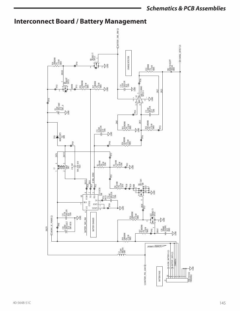
Schematics & PCB Assemblies
14540-5648-51C
Interconnect Board / Battery Management

Schematics & PCB Assemblies
146 40-5648-51C
Interconnect Board / Infrared Serial Communications

Schematics & PCB Assemblies
14740-5648-51C
Interconnect Board Assembly Drawing Top Side:
Bottom Side:
D1 U4 1
J5

Schematics & PCB Assemblies
148 40-5648-51C
Interconnect board assembly – parts list # QTY REF. Designator Package Value Part Spec1 7 C1,C2,C14,C15,C16, C17,C19 1206W 0.1UF CAPACITOR, 50V, X7R, 10%,
1206; GMC31X7R104K50NT, CAL-CHIP
2 4 C3, C4, C5, C6 0805W .01UF CAPACITOR, 50V, X7R, 10%, 0805; GMC21X7R103K50NT, CAL-CHIP
3 1 C7 TANT_B 10UF TCMIA106BT, CAL-CHIP; TAJB106M010R, AVX; T491B-106M010AS, KEMET
4 1 C8 TANT_D 22UF CAPACITOR, 25V, TANT, 10%, SMT_D; TPSD226M025R0200, AVX; T495D226M025AS, KEMET
5 2 C9, C10 SMT_8X10_8 220UF CAPACITOR, 35V, ELECT, 20%, RA-DIAL; NACZ221M35V8X10.8TR13, NIC; 35VCV220GX, SURGE COM-PONENTS
6 3 C11, C12, C13 1206W 0.22UF CAPACITOR, 25V, X7R, 10%, 1206; GMC31X7R224K25NE, CAL-CHIP
7 1 C18 1825 1UF CERAMIC, 1UF, 50V, X7R, 10%, 1825; GMC45X7R105K50NT, CAL-CHIP
8 1 C20 0805W 1000PF CAPACITOR, 50V, NPO, 5%, 0805; GMC21CG102J50NT, CAL-CHIP
9 1 C21 0805W 100PF CAPACITOR, 50V, NPO, 5%, 0805; GMC21CG101J50NT, CALCHIP
10 6 D1, D2, D3, D4, D5, D17 SOT23 MMBD914LT1, MOTOROLA11 2 D9, D10 SMB_X MURS120T3, MOTOROLA;
CMR1U-02, CENTRAL SEMI-CONDUCTOR
12 2 D11,D12 SMC CMSH3-60, CENTRAL SEMI; 30BQ060, INTERN. RECTIFIER
13 1 D14 LEADED_IR DN504, STANLEY14 1 D15 SOD-123 6.2V MMSZ5234BT1, MOTOROLA15 1 D16 SOD-123 5.6V MMSZ5232BT1, MOTOROLA16 2 FB1,FB2 0805W BLM21A102SPT, MURATA ERIE17 1 J1 10P_079RATH-
HDR1306-10-R-02, SINGATRON
18 1 J2 2P_079THHDR B2B-PH-K, JST19 1 J3 2P_100THHDR 22-03-5025, MOLEX20 1 J4 Cable 26 pin 12121-09-A, Singatron21 1 J5 DC_JACK DC-001-B-CRSN, POWER DY-
NAMICS22 1 L1 SMT_TOROID 10U 10UH, +/-20%, SMT TOR-
OID; CTX10-1, COILTRONIX; 618-100M-01, C&K MAGNETICS

Schematics & PCB Assemblies
14940-5648-51C
# QTY REF. Designator Package Value Part Spec23 1 L2 SMT_INDUC-
TOR13.3UH NL453232-3R3K, CAL-CHIP;
IMC-1812 3.3UH 10%, DALE24 1 L3 TH_10MMX7_
5MMPLT2003C, MURATA ERIE
25 1 PS1 POLYSWX_RA-DIAL
RUE185, RAYCHEM
26 4 Q1, Q8, Q10, Q23 SOT23 2N7002-T1, TEMIC; CENTRAL SEMICONDUCTOR
27 2 Q2, Q3 SOT23 MMBT2907ALT1, MOTOROLA28 2 Q4, Q5 SOT23 MMBT2222ALT1, MOTOROLA29 1 Q6 SO8 IRF7201, INTERN. RECTIFR;
SI9410DY, TEMIC30 1 Q7 SO8 MMSF3P02HD,MOTOROLA;
SI9430DY,SILICONIX (TEMIC)31 2 Q9, Q11 SOT23 TP0610T, Supertex, Vishay SILI-
CONIX (TEMIC) (Obsolete)32 2 R1, R23 1206W 100.0OHM RESISTOR, 1/8W, TCR=100PPM,
1%, 1206; RM10F1000CT, CAL-CHIP
33 1 R2 1206W 24OHM RESISTOR, 1/8W, TCR=400PPM, 5%, 1206; RM12J240CT, CAL-CHIP; ERJ-8GEYJ240V, PANA-SONIC
34 1 R3 1206W 1.5OHM RESISTOR, 1/8W, TCR=400PPM, 1%, 1206; ERJ8RQF1R5V, PANA-SONIC; RM12F1R5CT, CAL-CHIP; WCR12062R49F, IRC
35 1 R4 2010 0.5OHM RESISTOR, 1/2W, TCR=100PPM, 1%, 2010; WSL2010R500F, DALE; LR2010001R500F, IRC
36 6 R5, R10, R14, R19, R24, R26 0805W 200KOHM RESISTOR, 1/10W, TCR=200PPM, 5%, 0805; RM10J204CT, CAL-CHIP
37 5 R6, R9, R15, R16, R27 0805W 10.0KOHM RESISTOR, 1/10W, TCR=100PPM, 1%, 0805; RM10F1002CT, CAL-CHIP
38 4 R7, R8, R17, R29 0805W 1.0KOHM RESISTOR, 1/10W, TCR=100PPM, 1%, 0805; RM10F1001CT, CAL-CHIP
39 1 R11 0805W 2.0KOHM RESISTOR, 1/10W, TCR=100PPM, 1%, 0805; RM10F2001CT, CAL-CHIP
40 1 R12 0805W 392.0KOHM RESISTOR, 1/10W, TCR=100PPM, 1%, 0805; RM10F3923CT, CAL-CHIP
41 1 R13 0805W 100OHM RESISTOR, 1/10W, TCR=200PPM, 5%, 0805; RM10J101CT, CAL-CHIP
42 2 R18, R22 0805W 6.49KOHM RESISTOR, 1/10W, TCR=100PPM, 1%, 0805; RM10F6491CT, CAL-CHIP

Schematics & PCB Assemblies
150 40-5648-51C
# QTY REF. Designator Package Value Part Spec43 2 R20, R21 0805W 220OHM RESISTOR, 1/10W, TCR=200PPM,
5%, 0805; RM10J221CT, CAL-CHIP
44 1 R25 0805W 475.0OHM RESISTOR, 1/10W, TCR=100PPM, 1%, 0805; RM10F4750CT, CAL-CHIP
45 1 R28 0805W 20.0KOHM RESISTOR, 1/10W, TCR=100PPM, 1%, 0805; RM10F2002CT, CAL-CHIP
46 1 TVS1 DO_204AC SA13CA, On Semiconductor SA13CA Vishay Semiconductor
47 2 TVS2, TVS3 1206W VC120614D300D, AVX48 1 TVS4 0805W VC080505A150, AVX49 1 U1 LEADED_IR PS5042, STANLEY50 1 U2 SOT23-5 LMC7111BIM5, NATION-
AL SEMICONDUCTOR; MIC7111BM5, MICREL
51 1 U3 SOT23 MAX809LEURT, MAXIM; ADM-809LART, ANALOG DEVICES
52 1 U4 SOT23-5 LMC7211AIM5, NATION-AL SEMICONDUCTOR; MIC7211BM5, MICREL
53 1 U5 SO8 LT1512CS8, LINEAR TECH54 1 PCB N/A INTERCONNECT PCB RAW,
Medfusion® 3000 Series

Assembly Drawings & Parts Lists
15140-5648-51C
Assembly drawings The following section provides assembly drawings – exploded views, and detailed parts lists including Smiths Medical part numbers.
Always follow the procedures (including warnings/cautions) in “Parts Replacement” section of this manual while disassembling, replacing parts, and reas-sembling any Medfusion® 3000 Series pump.Note: Part numbers and pricing are subject to change without notice. See the website at www.smiths-medi-cal.com.
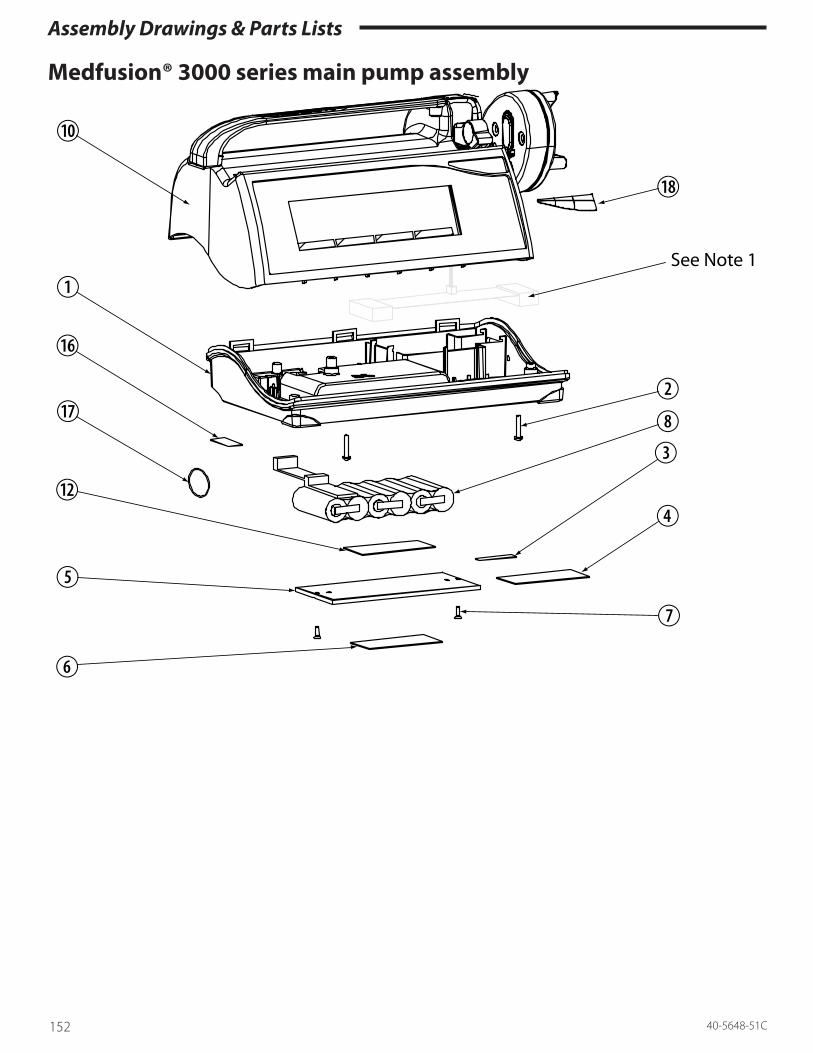
Assembly Drawings & Parts Lists
152 40-5648-51C
Medfusion® 3000 series main pump assembly
See Note 1

Assembly Drawings & Parts Lists
15340-5648-51C
Medfusion® 3000 series main pump assembly – parts listRef. # Part Number Description Quantity1 See following drawing Assembly Case Bottom 1 ea.2 G6000059 Screw, 4-40 × .62 PH Phillips 2 ea.3 No longer required Label, Device Tracking 1 ea.4 G6000775 Label, Warning 1 ea.
G6000763 Label, Warning, CE Mark 1 ea.G6000354 Label, Warning, German 1 ea.
5 G6000112 Door, Battery Bay 1 ea.6 G6002083 Label, Serial Number (Blank) 1 ea.7 G6000117 Screw 4-40 × .31 FH SS 2 ea.8 G6001392 Battery Assy, 3000 1 ea.10 See following drawing Assembly Case Top w/Plunger Head 1 ea.12 G6000979 Label, Battery Warning 1 ea.16 See note 2 Label, Date of Manufacture 1 ea.17 G6000418 Label, MRI Warning 1 ea.
G6000623 Label, MRI Warning, German 1 ea.G6000631 Label, MRI Warning, Spanish 1 ea.
18 G6000142 Label, Protege Logo 1 ea.G6000541 Label, Medfusion® 3010A Logo 1 ea.G6000605 Label, Medfusion® 3500 Logo 1 ea.
Notes: 1. Older model pumps may have this connector cable. In current pumps this cable is connected to the interconnect PCB.2. This label changes yearly. Please specify the manufacturing year shown on your pump when communicating with the Service Center.

Assembly Drawings & Parts Lists
154 40-5648-51C
Case bottom assembly
Medfusion™ 3500BC

Assembly Drawings & Parts Lists
15540-5648-51C
Case bottom assembly – parts listSee also case bottom service assembly, note 4 below.
To obtain replacement labels with the CE mark and na-tional language, international customers must order the International Case Bottom Assy. See note 4 below.
Ref. # Part Number Description Quantity1 G6000094 Case Bottom - No Feet (See note 4) 1 ea.
G6000754 Case Bottom - With Feet (See note 4) 1 ea.3 G6000014 Speaker Assembly 1 ea.4 G6000312 PCB Assembly, Interconnect (see note 6) 1 ea.5 G6000773 Power Supply, Conformal Coated 1 ea.6 G6000016 Shield, Power Supply 1 ea.7 G6000017 Lens, IR Window 1 ea.8 G6000276 Cable, AC Power 1 ea.
G6000102 Cable, AC Power, Medfusion® 3500E 1 ea.G6000695 Cable, AC Power, Medfusion® 3500BC (See note 9) 1 ea.
9 G6000693 Screw, 4-40 × .31 PH Phillips 6 ea.10 G6000220 Clamp, Cord Retainer 1 ea.11 G6000192 Locknut, 6BA Nylock 2 ea.12 G6000410 Washer, Shoulder, Nylon 2 ea.13 G6000118 Pad, Battery Bay 1 ea.14 G6000012 Cable, DC Power 1 ea.15 G6000387 Cable 1 ea.16 0340IF1400 Solder17 G6000706 Feet, Rubber (glue type) (See note 5) (See note 7) 4 ea.18 G6000694 Label, Functional Ground (See note 8) 1 ea.
Notes: 1. In newer assemblies, the interconnect PCB assem-bly (item 4) P/N G6000312 has superseded the older assembly P/N G6000234. 2. In older assemblies, items 10 & 11 are Screw, 4-40 × .38 FH SS (G6000127) and Nut, 4-40 Nylock (G6000043). 3. In newer assemblies, the shoulder washer (item 12) has superseded the flat washer, Smiths Medical P/N G6000058.4. Items 1, 17 (four pieces), 7, 13 and labels are avail-able as a service subassembly part number: English: G6000438, Case Bottom Assembly – Ser-
vice (USA) International: G6000622, Case Bottom Assy Ger-
man – Service5. Use with Loctite® 401, part number 036LT40100.
Notes (continued): 6. Board comes with cable (#G6000387) attached.7. Older models use Enlarged rubber foot (#G6000287). 8. Item 18 is adhered to the top of the AC power cable.9. Item 8 ring terminal is secured at secondary-side mounting post of power supply.

Assembly Drawings & Parts Lists
156 40-5648-51C
Case top assembly w/plunger

Assembly Drawings & Parts Lists
15740-5648-51C
Case top assembly w/plunger – parts listSee also plunger case left service assembly, note 1 below.
Ref. # Part Number Description Quantity1 G6000067 Mount, Plunger Head 1 ea.2 G6000068 Force Sensor 1 ea.3 G6000069 Plate, Plunger Float 1 ea.4 G6000755 Case Left, Plunger (See note 1) 1 ea.5 G6000071 Cam Gear, Plunger 1 ea.6 G6000725 Flipper, Plunger 2 ea.7 G6000074 Case Right Plunger 1 ea.8 G6000180 Assy PCB Plunger, Tested Service 1 ea.9 G6000925 Timing Plate Left 1 ea.10 G6000926 Push Block 1 ea.11 G6000085 Screw, M4 × 12, Button Head 2 ea.12 G6000086 Spring, .21 OD × 1.5 2 ea.13 G6000669 Lever, Plunger 1 ea.14 G6000089 Gear, Plunger Flipper 2 ea.16 G6000087 Gear, Plunger Lever 1 ea.17 G6000082 Seal, Flipper 2 ea.18 G6000927 Timing Plate Right 1 ea.19 G6000083 Seal, Lever 1 ea.20 G6000103 Screw 4-40 × ⅞ Pan Phil SS 1 ea.21 G6000110 Pin, Dowel 1 ea.22 G6000105 Screw, 4-40 × ⁷/₁₆ Pan Phil SS 2 ea.23 G6000749 Screw, 4-40 × .18 FH SS 2 ea.25 G6000090 Seal, Plunger Case 1 ea.26 G6000474 Washer, Flat #4, SS 1 ea.27 G6000693 Screw, Pan Phil, 4-40 1/4 SS 2 Ea.28 See following drawing Assy, Case Top w/o Plunger 1 ea.31 G6000544 Screw, 6-19 × ½ (See note 3) 2 ea.32 G232100076 Loctite Black Max35 G6001656 O-ring (See note 2) 1 ea.
Notes: 1. Items 3, 4, 6 (two pieces), 14 (two pieces), and 17 (two pieces), and 31 (two pieces) are available as a service subassembly part number G6000439, Plunger Case Left Assembly - Service.2. New style plunger case requires o-ring (older mod-els do not require this part). 3. Use with Loctite® Black Max, part number G232100076 (Item 32).

Assembly Drawings & Parts Lists
158 40-5648-51C
Case top assembly without plunger

Assembly Drawings & Parts Lists
15940-5648-51C
Case top assembly without plunger – parts listSee also case top service assembly, note 2 below.
Ref. # Part Number Description Quantity1 See note 2. Case Top, With Tubing Holders 1 ea.2 See note 4. Keypad 3000 1 ea.3 G6000021 Stud Self Clench 4-40 × 625 2 ea.4 G6000022 Spacer, .25 OD × .31, Nylon 2 ea.5 G6001457L Display, Liquid Crystal 1 ea.6 G6000023 Ear Clip 1 ea.7 See following drawing Assembly Barrel Clamp 1 ea.8 G6000034 E-Ring 1 ea.9 See following drawing Assembly Drive Train 1 ea.10 See note 3 Assy 3000 Main PCB 1 ea.11 G6000010 Optocoupler Assembly 1 ea.12 G6000692 Screw 4-40 × .31 Phillips 10 ea.13 G6001999 Case Handle 1 ea.14 G6000101 Backlight Fiber Optic (Medfusion® 3010A Series) 1 ea.
G6000582 Backlight Fiber Optic Dual LED (Medfusion® 3500 Series) 1 ea.15 G6000064 Standoff Hex 4-40 × .38 3 ea.16 G6000043 Nut 4-40 Nylock 4 ea.18 G6000122 Seal, Barrel Clamp/Ear Clip 2 ea.19 G6000077 Tube Seal 1 ea.21 G6000474 Washer, #4 Flat 2 ea.22 G6000715 Barrel Clamp Head 1 ea.23 G6000802 Screw 4-40 × .25 BH Black 1 ea.27 G6000257 Clamp, Stainless Steel 1 ea.28 G6000903 Screw, Pan Phil 2-56 3/₁₆ SS Nylock 1 ea.32 0382000000 Grease, Silicone 111 0.1 oz.33 G6000339 Lens, Keypad Support 1 ea.35 G6000393 Sleeve, Ear Clip 1 ea.36 G6000397 Spring, Ear Clip 1 ea.37 G6000583 Spacer, LCD, Backlight (see note 5) 1-2 ea.38 039TT10200 Wire Tie (Medfusion® 3500 Series) 1 ea.39 G6000585 Cable, Backlight Dual LED (Medfusion® 3500 Series) 1 ea.40 G6000692 Nylok Screw 3 ea.41 G6000238 Tube Holder 3 ea.
- continued on next page -

Assembly Drawings & Parts Lists
160 40-5648-51C
Notes: 1: Item 35 does not appear in older pumps.
2: Items 1, 2, 3 (two pieces), 13, 18, 19 and 33 are avail-able as a service subassembly part number:
For Medfusion® 3010 and 3010a: G6000437, Case Top Protege Assembly - Service (old style barrel clap head and no keyway) G6000736, Case Top Protoge Assembly - Service (new style barrel clamp with keyway)
For Medfusion® 3500 (English): G6000610, Case Top 3500 – Service (old style barrel clamp head and no keyway) G6000737, Case Top 3500 - Service (new style bar-rel clamp with keyway)
For Medfusion® 3500 (International): G6000624, 3500 International Case Top - Service English: G6000438, Case Bottom Assembly – Ser-vice
International: G6000622, Case Bottom Assy Inter-national – Service
3: Items 10 is available as service subassembly part numbers:
G6000435, 3010 Main PCB Assembly – Software Version 2.0.6 - Service
G6000361, 3500 Main PCB Assembly – Software Version 3.0.6 - Service
G6001260, 3500 Main PCB Assembly – Software Version 4.0.2 - Service
G6001560, 3500 Main PCB Assembly – Software Version 4.1.5 - Service
G6001561, 3500 Main PCB Assembly – Software Version 3.0.9 - Service
G6001562, 3500 Main PCB Assembly - Software Version 4.1.4 -Service
Check with the Smiths Medical service department for other software versions.
4: Item 2, for Medfusion® 3010 English Text Keypad use G6000005. For Medfusion® 3500 English Text key-pad use G6000607. For Medfusion® 3500 International Keypad use G6000912.
5: Early Medfusion® 3010 pumps have no spacer, later Medfusion® 3010 pumps have 2 spacers. All Medfusion® 3500 and later pumps have 1 spacer.

Assembly Drawings & Parts Lists
16140-5648-51C
Barrel clamp assembly
GREASE
SILICONE III
SOLDERNO CLEAN

Assembly Drawings & Parts Lists
162 40-5648-51C
Barrel clamp assembly – parts listRef. # Part Number Description Quantity1 G6000716 Guide Barrel Clamp 1 ea.2 G6000904 Rod Barrel Clamp 1 ea.4 G6000031 Barrel Clamp Slide 1 ea.5 G6000032 Spring, Barrel Clamp 1 ea.6 G6000024 Spring .265 ID × .5 1 ea.7 G6000186 - See note 1 Pot Size Sensor, 10K 1 ea.8 G6000096 - See note 1 Flex Cable Size Pot 1 ea.9 G6000121 Screw #2 × .18 Plastite 1 ea.11 0340IF1400 - See note 1 .030 DIA, Spool Solder 0.01 oz.12 0382000000 Grease, Silicon 111 0.1 oz.13 G6000906 Screw, 6-32 ¼” Truss Nylock 1 ea.
Notes: 1: These items 7, 8 and 9 are available as a service subassembly part number G6000436, Size Sensor Pot Assembly - Service.

Assembly Drawings & Parts Lists
16340-5648-51C
Drive train assembly
SEE
NO
TE 2
111
GRE
ASE
RED
GRE
ASE
RIG
HT
SID
E VI
EWLE
FT S
IDE
VIEW

Assembly Drawings & Parts Lists
164 40-5648-51C
Drive train assembly – parts listRef. # Part Number Description Quantity1 See following drawing Assembly Clutch 1 ea.2 G6000931 Extrusion Main 1 ea.3 G6000717 Assy Right End Plate 1 ea.4 G6000049 Plate Motor Mount 1 ea.5 See note 2 Motor Stepper 7.5 Degree 1 ea.6 G6001599 Pot Position 10K, 20% 1 ea.7 G6000053 Bushing .19 ID × .25 Delron 2 ea.8 G6000055 Rod, Guide, Precision 1 ea.9 G6000056 Thrust Bearing 1 ea.10 G6000058 Washer Steel .438 × .125 × .031 1 ea.11 G6000059 Screw 4-40 × .62 PH Phillips 1 ea.12 G6000043 Nut 4-40 Nylock 4 ea.13 See note 1 Worm 1 ea.14 G6001459 Leadscrew 1 ea.15 G6000051 Gear, Worm 1 ea.16 G6000057 Bushing, Leadscrew, Right 1 ea.17 G6000075 Screw 6-20 × .5 FH Thread Form 7 ea.18 G6000902 Screw, 2-56 × .19 FH SS 1 ea.19 G6000072 Washer Brass .340 × .117 × .050 1 ea.20 See note 2 Washer, Teflon®, .312 × .093 × .010 1 ea.
21 G6000063 Screw, 4-40 × .31 PH Phillips 2 ea.22 See note 2 Shaft Driver 1 ea.23 07020STP00 Grease, STP 0.1 oz.24 G6000791 Washer, Wave Spring, .490 × .326 × .010 1 ea.26 036LT24200 Loctite® 242 0.01 oz.
27 See note 1 Coupling, Worm 1 ea.28 0391331800 E-Clip 1 ea.30 G60001223 Washer, Teflon® A/R
Notes: 1: Items 13 and 27 are bonded together to form a worm assembly, in older pumps these may appear as a single machined part. These items are available as a service subassembly part number G6001480, Worm/Coupling Assembly - Service. 2: Items 22, 20, and 5 are available as a service subas-sembly part number G6000431, Motor Service Assem-bly - Service.

Assembly Drawings & Parts Lists
16540-5648-51C
Clutch assembly
RED GREASERED GREASE
RED GREASE
Clutch assembly – parts list
Ref. # Part Number Description Quantity1 G6000099 Carriage 1 ea.2 G6000928 Clutch, Left 1 ea.3 G6000929 Clutch, Right 1 ea.4 G6000924 Cam, Clutch 1 ea.5 G6000905 Plate, Carriage 1 ea.6 G6000044 Spring, Clutch 1 ea.7 G6000045 Tube Plunger 1 ea.
G6000738 Insulated Tube 1 ea.8 0391331800 E-Clip 1 ea.9 G6000378 Square Shaft (See note below) 1 ea.10 G6000063 Screw 4-40 × .31 PH Phillips 3 ea.11 G6000310 Nut, Nylock, 4-40, SS, Small 3 ea.12 G6000749 Screw 4-40 × .18 FH SS 2 ea.13 G6000159 Assembly, Plunger Cable 1 ea.15 07020STP00 Grease, STP 0.1 oz.
Notes: In newer pumps, square shaft (item 9) is being superseded by SS Square Shaft, P/N G6000378.

Assembly Drawings & Parts Lists
166 40-5648-51C
Accessories – parts listPoleclamp assembly
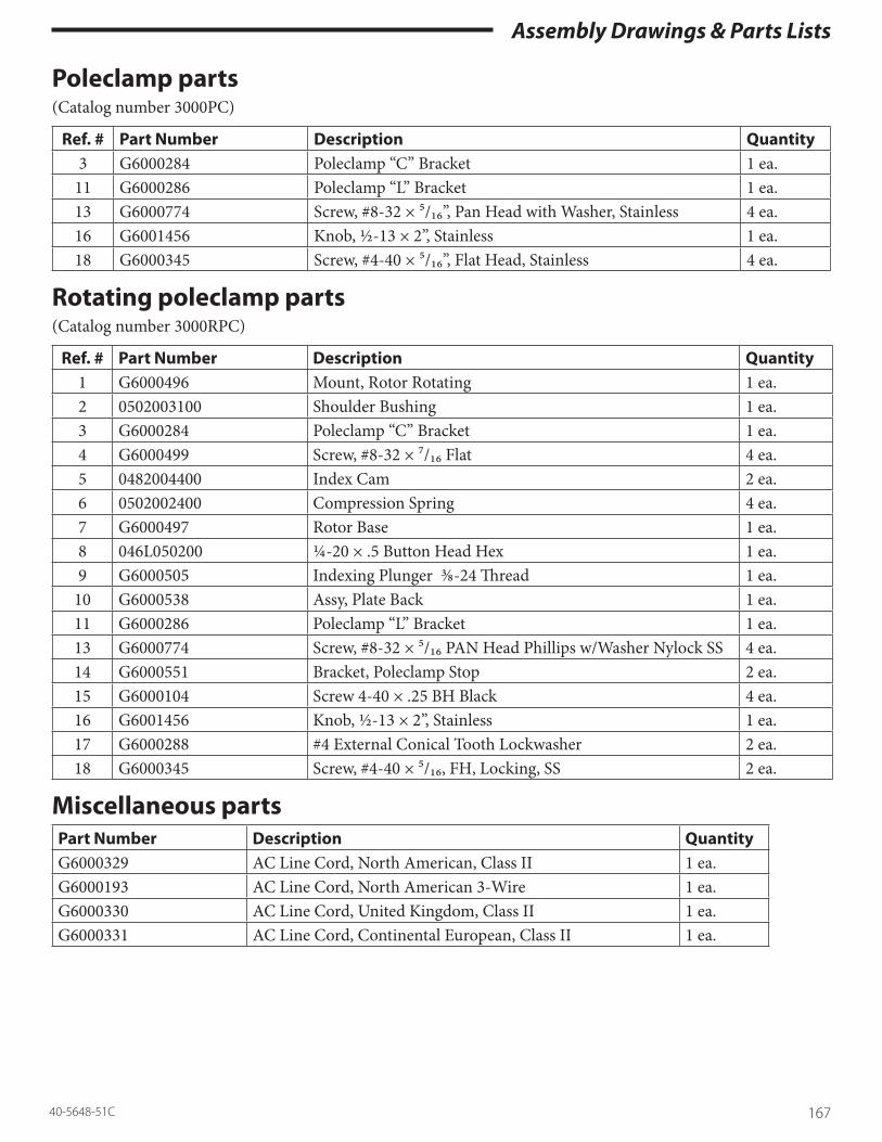
Assembly Drawings & Parts Lists
16740-5648-51C
Poleclamp parts(Catalog number 3000PC)
Ref. # Part Number Description Quantity3 G6000284 Poleclamp “C” Bracket 1 ea.
11 G6000286 Poleclamp “L” Bracket 1 ea.13 G6000774 Screw, #8-32 × ⁵/₁₆”, Pan Head with Washer, Stainless 4 ea.16 G6001456 Knob, ½-13 × 2”, Stainless 1 ea.18 G6000345 Screw, #4-40 × ⁵/₁₆”, Flat Head, Stainless 4 ea.
Rotating poleclamp parts (Catalog number 3000RPC)
Ref. # Part Number Description Quantity1 G6000496 Mount, Rotor Rotating 1 ea.2 0502003100 Shoulder Bushing 1 ea.3 G6000284 Poleclamp “C” Bracket 1 ea.4 G6000499 Screw, #8-32 × ⁷/₁₆ Flat 4 ea.5 0482004400 Index Cam 2 ea.6 0502002400 Compression Spring 4 ea.7 G6000497 Rotor Base 1 ea.8 046L050200 ¼-20 × .5 Button Head Hex 1 ea.9 G6000505 Indexing Plunger ⅜-24 Thread 1 ea.
10 G6000538 Assy, Plate Back 1 ea.11 G6000286 Poleclamp “L” Bracket 1 ea.13 G6000774 Screw, #8-32 × ⁵/₁₆ PAN Head Phillips w/Washer Nylock SS 4 ea.14 G6000551 Bracket, Poleclamp Stop 2 ea.15 G6000104 Screw 4-40 × .25 BH Black 4 ea.16 G6001456 Knob, ½-13 × 2”, Stainless 1 ea.17 G6000288 #4 External Conical Tooth Lockwasher 2 ea.18 G6000345 Screw, #4-40 × ⁵/₁₆, FH, Locking, SS 2 ea.
Miscellaneous partsPart Number Description QuantityG6000329 AC Line Cord, North American, Class II 1 ea.G6000193 AC Line Cord, North American 3-Wire 1 ea.G6000330 AC Line Cord, United Kingdom, Class II 1 ea.G6000331 AC Line Cord, Continental European, Class II 1 ea.

Assembly Drawings & Parts Lists
168 40-5648-51C
Calibration & repair – parts listMedfusion® 3000 series calibration kitThe Biomed Medfusion® 3000 Series Calibration Kit contains the tools necessary for performing the peri-odic maintenance and calibration of the Medfusion® 3000 Series pumps.
Order kit number 3000CAL.
This kit contains the following items :
• 1 ea. − Small Calibration Slug, G6000216• 1 ea. − Large Calibration Slug, G6000215• 1 ea. − Analog Force Gauge, G6000294
Other tools & equipment required to service Medfusion® 3000 series pumpsThe following tools are necessary for performing the maintenance, parts replacement, and diagnosis of the Medfusion® 3000 Series pumps.
• 1 ea. − 50 or 60cc syringe (see Operations Manu-al for list of acceptable types)
• 1 ea. − Medium bore tubing set, Smiths Medical 53-60-225 or equivalent
• 1 ea. − 3 Way Stopcock• 1 ea. − Torque Screwdriver with #1 Phillips bit,
#0 Flat bit, & 2.5mm Hex bit • 1 ea. − ³/₁₆” nut driver• 1 ea. − ¼” open end wrench or nut driver• 1 ea. − .002” shim or feeler gauge• 1 ea. − Pliers, standard & needle nose• 1 ea. - Calipers

Assembly Drawings & Parts Lists
16940-5648-51C
Notes_____________________________________________
_____________________________________________
_____________________________________________
_____________________________________________
_____________________________________________
_____________________________________________
_____________________________________________
_____________________________________________
_____________________________________________
_____________________________________________
_____________________________________________
_____________________________________________
_____________________________________________
_____________________________________________
_____________________________________________
_____________________________________________
_____________________________________________
_____________________________________________
_____________________________________________
_____________________________________________
_____________________________________________
_____________________________________________
_____________________________________________
_____________________________________________
_____________________________________________
_____________________________________________
_____________________________________________
_____________________________________________
_____________________________________________
_____________________________________________
_____________________________________________
_____________________________________________
_____________________________________________
_____________________________________________
_____________________________________________
_____________________________________________
_____________________________________________
_____________________________________________
_____________________________________________
_____________________________________________
_____________________________________________
_____________________________________________
_____________________________________________
_____________________________________________
_____________________________________________
_____________________________________________
_____________________________________________
_____________________________________________
_____________________________________________
_____________________________________________
_____________________________________________
_____________________________________________
_____________________________________________
_____________________________________________
_____________________________________________
_____________________________________________
_____________________________________________
_____________________________________________
_____________________________________________
_____________________________________________
_____________________________________________
_____________________________________________
_____________________________________________
_____________________________________________
_____________________________________________
_____________________________________________
_____________________________________________
_____________________________________________

Assembly Drawings & Parts Lists
170 40-5648-51C
_____________________________________________
_____________________________________________
_____________________________________________
_____________________________________________
_____________________________________________
_____________________________________________
_____________________________________________
_____________________________________________
_____________________________________________
_____________________________________________
_____________________________________________
_____________________________________________
_____________________________________________
_____________________________________________
_____________________________________________
_____________________________________________
_____________________________________________
_____________________________________________
_____________________________________________
_____________________________________________
_____________________________________________
_____________________________________________
_____________________________________________
_____________________________________________
_____________________________________________
_____________________________________________
_____________________________________________
_____________________________________________
_____________________________________________
_____________________________________________
_____________________________________________
_____________________________________________
_____________________________________________
_____________________________________________
_____________________________________________
_____________________________________________
_____________________________________________
_____________________________________________
_____________________________________________
_____________________________________________
_____________________________________________
_____________________________________________
_____________________________________________
_____________________________________________
_____________________________________________
_____________________________________________
_____________________________________________
_____________________________________________
_____________________________________________
_____________________________________________
_____________________________________________
_____________________________________________
_____________________________________________
_____________________________________________
_____________________________________________
_____________________________________________
_____________________________________________
_____________________________________________
_____________________________________________
_____________________________________________
_____________________________________________
_____________________________________________
_____________________________________________
_____________________________________________
_____________________________________________
_____________________________________________
_____________________________________________
_____________________________________________
_____________________________________________
_____________________________________________

Index
17140-5648-51C
IndexA
Accessories 67, 166AC input assembly 79, 80
Removing 79Replacing 79
Verifying 80AC line leakage test 9, 12, 17, 22AC Power 4, 16, 75AC power detection description 49AC power input & power supply board 30, 79AC power supply 79
Removing 79Replacing 79
Verifying 79Adjust contrast (display) 105Adjust contrast (voltage) setting 7, 65, 96, 105Alarm history 72Alarm message 9, 53Alarms / alerts 10, 53, 60, 65
High priority 11, 53Limit priority 11, 53Low priority 11, 53Medium priority 11, 53System failure 12, 29, 59, 61system fault 27
Always on supply 38Analog supply 33, 40, 61, 71Analog to digital converter 32, 33, 35, 63, 70, 71Annual maintenance 19Asembly, clutch 84, 165Assembly, barrel clamp 82, 83, 84, 88, 90, 91, 108, 159,
160, 162Assembly, case bottom 80, 108, 153, 154, 155Assembly, case top without plunger 157, 158, 159Assembly, case top with plunger 153, 155, 157Assembly, drive train 82, 159, 163, 164Assembly drawings 3, 151Audio test 69
BBacklight 6, 11, 43, 82, 86, 87, 88, 108, 159
Removing 86Replacing 87Supply 41
Backup audio buzzer 9, 38, 39Backup super capacitor 9, 38Barrel clamp 4, 19, 27, 54
Assembly 82, 83, 84, 88, 90, 91, 108, 159, 161, 162Body 88Head 88, 159
Barrel clamp body 88Removal 88Replacement 89
Barrel clamp head 88Removal 88Replacement 88
Verifying 88Battery 6, 10, 11, 17, 30, 52, 54, 56, 62, 65, 77, 153
Calibration 24Charger 51, 52Compartment 76gauge 9, 51, 52
Schematic 143Maintenance 24Management 51, 145Monitoring status 70Replacing 25, 75, 77, 108
Requirements 25Verifying 77
Switchover 52Battery board 52Battery gauge 9, 30, 51, 52, 143Biomed menu
Accessing 68Calibration 10, 68, 95
Calibrate (syringe) size and position 96, 97Size sensor 20, 29
Calibrate force sensor 96, 100Calibrate plunger position sensor 21, 96, 102Calibrate pressure sensor 96, 102Exit calibration without saving changes 107
Diagnostics 10, 68, 69, 70Audio test 69Display test 69Drive train test 70Indicator test 69Keypad test 70Monitor 6811 a2d group1 71Monitor 6811 A2D group2 71Monitor a2d selftest 71Monitor analog sensors 70Monitor digital sensors 70

Index
172 40-5648-51C
Motor drive test 71major options 7Set language 69, 73Understanding 7Update firmware 69, 73Utilities 69
Set/view last (or next) PM date 71Set time & date 72View alarm history 72View infusion history 72View service data 72View software CRCs & view software versions 72
View EEPROM size 72Bottom housing. See Case Bottom assembly
CCalendar clock. See Clock, real timeCalibrate (syringe) size and position 96, 97Calibrate force sensor 96, 100Calibrate plunger position sensor 96, 102
sensor check 21Calibrate pressure sensor 96, 102Calibrating the battery. See BatteryCalibration and adjustment 95
Verification 20Calibration kit 15, 95Calibration menu 68, 95
Adjust contrast (display) 105Calibrate (syringe) size and position 96, 97
Size sensor 20, 29Calibrate force sensor 96, 100
Force sensor check 20Calibrate plunger position sensor 96, 102
Check 21Calibrate pressure sensor 96, 102Exit calibration without saving changes 107
Case bottom assembly 80, 108, 153, 154, 155Removing 80Replacing 80
Case top without plunger assembly 157, 158, 159Case top with plunger assembly 153, 155, 157Charge detector (battery) 51, 52Cleaning and care 18
Cleaning cautions 18Clock, real time 10, 29, 33, 38, 60, 64, 72Closing the pump 76Closing the pump housing 76Clutch assembly 84, 165
Controlling motor functions 27CPI (Capacity Inaccurate), battery 10, 24
DData input / output to LCD 43DC power converter 29DC power input jack 30DC to DC converter 40Depleted battery monitor 10, 52Diagnostics menu 10, 69
Audio test 69Display test 69Drive train test 70Indicator test 69Keypad test 70Monitor 6811 a2d group1 71Monitor 6811 A2D group2 71Monitor a2d selftest 71Monitor analog sensors 70Monitor battery status 70Monitor digital sensors 70Motor drive test 71
Digital to analog converter 32, 33, 35Display. See LCDDisplay test 69Drive train assembly 82, 159, 163, 164
Test 70Drive train test 70
EEar sensor. See Syringe flange sensorEEPROM. See Serial EEPROMESD (Electrostatic Discharge) 1, 15, 75ESD warning 8Exit calibration without saving changes 107Expansion port # 1 36Expansion port # 2 37External DC power conditioning / detection 50
FFlash memory 11, 34, 62
Reprogramming 34Force preamplifier function 47Force sensing interface 47Force sensor check 20Front panel interface 42

Index
17340-5648-51C
GGlossary 9Graphical display circuit board 29Graphic display interface 43, 123
HHigh priority 11, 53
II/O port expansion 36Indicator test 69Infrared receiver 50Infrared serial data port 11, 50Infrared transceiver 34Infrared transmitter 50Infusion Class 4 8, 11Infusion Class 5 8, 11Infusion history 72Interconnect printed circuit board 11, 29, 78, 108, 155
Assembly drawing 147, 148Removing 78Replacing 78
Verifying 78Schematic 49, 144
IPX3 11
KKeypad 4, 5, 19, 29, 42, 61, 65, 66, 108, 120, 159
Removing 87Replacing 88
Keypad test 11, 70
LLCD 4, 86, 108, 123, 159
Adjust contrast 105Backlight 6, 11, 43, 86
Supply 41Removing 86Replacing 86
Verifying 87LED drive circuit 42LMD (Last Measured Discharge), battery 10, 11Logic core 28, 116Logic kernel 31
Schematic 112Logic supply 40, 63
Low priority 11, 53
MMain microprocessor 28, 31Main microprocessor interface 31Main printed circuit board 28, 108, 159
Assembly drawing 131Removing 81Replacing 81Schematic 31, 112
Maintenance, Annual 19Maintenance, battery 24Maintenance, periodic 17maintenance tools 15Medium priority 11, 53Monitor 6811 a2d group1 71Monitor 6811 A2D group2 71Monitor a2d selftest 71Monitor analog sensors 70Monitor battery status 70Monitor digital sensors 70Motor current detector 36, 44Motor current regulators 40, 44Motor drive description 44Motor drive test 21, 71Motor rotation sensor 12, 27, 29Motor speed detection 45Motor supply 40, 71
NNegative supply 41NiCad battery pack 30NiMH battery pack 30Nominal voltage 52
OOpening the pump housing 76Overview of operation 27
PParts replacement 75Periodic maintenance 17Plunger (driver) travel sensor 29, 35, 46Plunger flipper sensor 48Plunger force sensor 30, 62, 108, 157
Calibrate 96, 100Removal 93

Index
174 40-5648-51C
Replacement 93Plunger loaded sensor 30Plunger position sensor 46, 63
Calibrate 96, 97, 102Test 21
Plunger printed circuit board 12, 30, 108, 157Assembly drawing 141Removal 92Replacement 93Schematic 47, 139
Power control 31, 34, 38, 116, 144Always on 38backup audio buzzer 9, 38Backup super capacitor 9, 38System reset 39
Power management 39Power OFF state 32, 39Power ON state 13, 32, 39Power supply PCB 79, 155
Removing 79Replacing 79
Verifying 79Power switch interface 42Problem solving 53. See also TroubleshootingProgramming flash memory 34Pump assembly 152
Closing the pump housing 76Opening the pump housing 76
Pump cleaning. See Cleaning and carePump design description 28Pump returns. See Returning a pump for repairPWM current references 44
RReal time clock. See Clock, real timeRechargeable battery pack 30Removing AC input module assembly 79
Replacing 79Removing AC power supply 79
Replacing 79Removing LCD and/or backlight assembly 86
Replacing 86Removing the bottom housing 80
Replacing 80Removing the keypad 87
Replacing 88Removing the main board 81
Replacing 81
Requirements for battery pack replacement 25Returning a pump for repair 67
SSafety Class II, Type CF equipment 9Screen. See DisplaySerial EEPROM 12, 34, 45, 64Service address. See Returning a pump for repairSet/view last (or next) PM date 71Set language 69, 73Set time & date 72Severely depleted battery monitor 52Shallow discharge (CPI) record 24Speaker 12, 28, 30, 32, 33, 36, 78, 108, 155
Detect 71Drive 129Removal 78Replacement 78
Verifying 78Speaker control 46Speaker detect 71Speaker drive description 46Speaker test 47, 65, 69
Standard cleaning. See Cleaning and careStatic random access memory 34Stepper motor 12, 27, 28, 29, 44, 63, 64Symbol definitions 8Syringe ear sensor. See Syringe flange sensorSyringe flange sensor 28, 29, 54, 58, 70Syringe size sensor 20, 29
Syringe size sensing 35, 45Description 45
System Failure 12, 29, 59
TTheory of operation 27Time of day clock. See Clock, real timeTroubleshooting 65, 68
UUpdate firmware 69, 73Utilities Menu 69, 71
Set/view last (or next) PM date 71Set time and date 72View alarm history 72View EEPROM size 72View infusion history 72

Index
17540-5648-51C
View service data 72View software CRCs & view software versions 72
VVerify AC power supply function 79Verifying AC input assembly module function 80Verifying battery function after new battery replace-
ment 77Verify interconnect board function 78Verify LCD & backlight assembly function 87View alarm history 72View calibration data 96, 106View EEPROM size 72View infusion history 72View service data 72View software CRCs & view software versions 72
WWatchdog 36, 39, 61
Alarm 9, 37, 39, 44Circuit 13, 29

Index
176 40-5648-51C


s
Medfusion, PharmGuard, and the Medfusion and Smiths Medical design marks are trademarks of the Smiths Medical family of companies. The symbol
® indicates the trademark is registered in the U.S. Patent and Trademark Office and certain other countries.
All other names and marks are trademarks, tradenames, or service marks of their respective owners.
U.S. and foreign patents pending.
© 2010 Smiths Medical family of companies.All rights reserved.2010-01 40-5648-51C
2
Smiths Medical ASD, Inc.St. Paul, MN 55112 USA1 800.258.5361 (USA), 1 214.618.0218www.smiths-medical.com
Smiths Medical International Ltd.WD24 4LG, UKTel. +44 (0)1923 246434
Smiths Medical Australasia Pty. Ltd. 61 Brandl Street Eight Mile Plains, QLD 4113, Australia.Tel: +61 (0)7 3340 1300


![—51C Y x—51C 30 · 2020. 3. 17. · 7k D (51] & s c < < 06-6345-6405 . Created Date: 3/17/2020 4:51:13 PM](https://static.fdocuments.in/doc/165x107/60b2677a4f20ec16b275e2f4/a51c-y-xa51c-30-2020-3-17-7k-d-51-s-c-06-6345-6405-.jpg)