Mechatronics approach to computer integrated decoration … · computer integrated decoration of...
314
•
Transcript of Mechatronics approach to computer integrated decoration … · computer integrated decoration of...
Loughborough UniversityInstitutional Repository
Mechatronics approach tocomputer integrated
decoration of scale models
This item was submitted to Loughborough University's Institutional Repositoryby the/an author.
Additional Information:
• A Doctoral Thesis. Submitted in partial fulfilment of the requirementsfor the award of Doctor of Philosophy of Loughborough University.
Metadata Record: https://dspace.lboro.ac.uk/2134/13707
Publisher: c© Luis Gonzaga Trabasso
Please cite the published version.

This item was submitted to Loughborough University as a PhD thesis by the author and is made available in the Institutional Repository
(https://dspace.lboro.ac.uk/) under the following Creative Commons Licence conditions.
For the full text of this licence, please go to: http://creativecommons.org/licenses/by-nc-nd/2.5/
LOUGHBOROUGH UNIVERSITY OF TECHNOLOGY
LIBRARY
AUTHOR/FILING TITlE
__________ __ ""Sff .. lY~A ~AQ.:;>. ___ '=-__ ~ ______ ______ _
ACCESSION/COPY NO.
_________________ __0_ J?..l~9...!?_~ _~!:·t( ____________ _ VOL. NO. CLASS MARK
-
• - 3 JUt 199£ l.~~ Cbey
. "
- 2 Jijt1993 28 ... / . . ~'996
~ 28 JUN1996
,.
..... ' .~
. "
.~@ ;>I~ 3 {) JIJN1995 28" lnQl;
."' ,
11J21~ii}\ U ~J~9
036000945 X
111111111111111111111 1111111111111111

MECHATRONICS APPROACH
TO COMPUTER INTEGRATED DECORATION
OF SCALE MODELS
by
Lu[s 'Gonzaga Trabasso
A Doctoral Thesis submitted in partial
fulfilment of the requirements for the award of
Doctor of Philosophy
of the Loughborough University of Technology
Department of Mechanical Engineering
Loughborough University of Technology
August 1991
© by Lufs Gonzaga Trabasso, 1991

If Lo:~~t:;r~~'!l U=~,ty J. of Technc l
."" \' I..<:-:">y : ~:;~<- ~~". q" i .. ~.--. ---I j (·-;--·~-----~·~1
U:~~.-c Sf, O-O:"~~ 6J ~q"lI"lG'13

to
lara, my wife,
Rafael and Gabriel, my sons,
Salvador and Catarina, my parents
and to Jacob, my grandfather (in loving memory)

There Is nothing I cannot master with the help
of the One who gives me strength. (Ph, 4,13)

DECLARATION
This is to certify that neither this thesis nor the original work contained therein
has been submitted in support of an application for a higher degree of this or
any other institution.

ACKNOWLEDGMENTS
I wish to express my sincere gratitude to Prof. J. R. Hewit, my supervisor. He
introduced me to Mechatronics and to the practical side of Engineering.
Thanks to him I found the challenge of going beyond simulation very enjoyable.
His remarkable creativity and constant good humoured spirits have been a
source of encouragement for me. His comments and criticisms have been
appreciated as much as his learned guidance and advice that inspired my work
and moulded this thesis.
I am immensely grateful to Mr. Alan P. Slade, Mechatronics technician, who
supported my work right from the beginning. His passion for scale model
racing is the reason why this work is applied to scale model manufacture. It
also revived a forgotten hobby of mine. The lively brainstorming sessions with
Alan and Prof. Hewit have greatly influenced this work. I am also very grateful
for his valuable comments to this manuscript. His support went far beyond the
problems that I have faced concerning this work; as a consequence, a
friendship has been built and I do appreciate it.
The staff members whose assistance were valuable to my work are too
numerous to mention. However, I would like to single out Mr. Ken Topley who
is responsible for the photographic material of this thesis. If I had to quantify
my gratitude to him I know at least that I should do it in imperial units. Thanks
also to Mr. Barry Ellis who built, in a most professional manner, a number of
mechanical components which are part of the physical embodiment of this
work. I am amazed by his excellence: I would ask for a mock up and he would
deliver a prototype.
I also thank Dr. Cezary Zieliftski from the Warsaw University of Technology for
his contribution to the development of the robot-vision calibration procedures,
his comments on this manuscript and for the Polish stamps as well.

I am grateful to the personnel of Hornby Hobbies Ltd. that in one way or
another were involved with this work. In particular, I wish to thank Mr. Keith
Tyler, their production manager, who so kindly allowed us to carry out the
necessary study of the decoration process on the factory floor.
I wish to thank Mrs. Janet Stevenson for her patience in proof-reading this
manuscript.
My studies were only possible thanks to my prolonged absence from the
Instituto Tecnol6gico de Aeronautica, Sao Jose dos Campos, Sao Paulo, Brazil,
and thanks also to a grant from the Conselho Nacional de Pesquisa (CNPq) -
Brazil.
To my family and to my friends I express my heartiest gratitude for their
continuous moral support and encouragement, and, most of all, for their
confidence in me.
Finally, I wish to express my deepest feelings of gratitude and love to my wife,
lara, who sacrificed four years of her career for my sake and our sons'. I am
most thankful for her enduring patience, joy and support that made my stay in
England not only possible, but indeed pleasurable.
SUMMARY
Much European manufacturing industry is heavily dependent on manual labour
and therefore vulnerable to Far Eastern competitors, who have the advantage
of lower labour costs. Automation is Europe's best hope of beating off this
oriental challenge.
This thesis describes a research programme to assess the benefits of
automation to a particular industrial process, that of decoration of scale models
of cars.
The aim of the project is to replace a traditionally manual series of operations
by flexible automation to provide the base for higherproductivity and a greater
degree of responsiveness to product change, leading to just-in-time
manufacture with reduced work-in-progress, while still retaining the high quality
associated with the product.
A proof-of-concept cell has been designed and commissioned using the
Mechatronics approach. This means that all mechanical, electronic and
computing possibilities have been taken into account and integrated from the
first stage of the design process. The configuration of the proof-of-concept cell
consists of five stations which provide the necessary functions for loading the
modeis from the moulding machine into the cell, identifying the models and their
positions, decorating and inspecting the models and finally, palletising them for
assembly.
The results of this Mechatronics approach to design and manufacture are two
fold: (a)the efficiency of the cell is enhanced because its functions are
allocated, in an optimal fashion, to three different but integrated technological
fields, Mechanical Engineering, Electronic Engineering and Computer Science;
(b)the cell can be rendered easily flexible by re-programming facilities
embedded in its components.
( i )
TABLE OF CONTENTS
Introduction 1
Chapter 1 Concepts of Mechatronics 7
1.1 Definitions of Mechatronics 10
1.2 Examples of mechatronic products and systems 16
1.2.1 Telescope mountings 16 1.2.2 Aircraft fly-by-wire system 17 1.2.3 The autofocus camera 18 1.2.4 Mechatronic transducers 19
1.3 The profile of the Mechatronics Engineer 20
1.3.1 The Japanese way 21 1.3.2 The North-American way 22 1.3.3 The European way 22
1.4 Mechatronics Design Methodology 28
Chapter 2 Mechatronics Design Methodology 31
2.1 Methodology versus creativity in the design activity 34
2.2 Up-to-date review of Mechatronics design aids and methodologies 35
2.2.1 Mechatronics scheme builder 35 2.2.2 Mechanical software generator 36 2.2.3 Common language of Mechatronics 36 2.2.4 The common ground of design in diverse domains 37
2.3 Mechatronics design definition
2.4 The Mechatronics design team
2.4.1 The LUT Mechatronics design team
2.5 Phases of the Mechatronics design process
2.5.1 Recognition of the need 2.5.2 Design requirements 2.5.3 Synthesis
( ii )
38
40
43
45
46 47 51
2.5.4 Analysis and optimisation 52 2.5.5 Evaluation 56 2.5.6 Presentation 56
Chapter 3 Industrial decoration processes 58
3.1 Decoration processes for plastics 61
3.1.1 Pad printing 61 3.1.2 Spray painting 69 3.1.3 Screen printing 71 3.1.4 Hot stamping 72 3.1.5 Ink jet printing 73 3.1.6 Comparison of the printing methods 75
3.2 Hornby Hobbies Ltd. 75
3.2.1 From 1952 to the present 76 3.2.2 Looking to the future 80 3.2.3 Decoration processes currently used 81
3.3 Loughborough University & Hornby Hobbies Ltd. cooperative effort 91
Chapter 4 Mechatronic decoration cell: design 94
4.1 Recognition of the need 97
4.2 Design requirements 98
4.2.1 Hierarchy of functional requirements 100 4.2.2 Choice of the principle for grasping the bodyshells
safely 113 4.2.3 Equipment available for commissioning of the
decoration cell 116
Chapter 5 Mechatronic decoration cell: mechanical synthesis
5.1 Loading station
5.1.1 Mechanical adjustments
5.2 Identification station
5.2.1 Side-lighting arrangement system 5.2.2 Handling mechanism of the bodyshells
( iii )
120
123
128
130
130 137
5.2.3 End-effectors utilised 144
5.3 Decoration station 150
5.3.1 The painter approach 151
5.3.2 The peg-in-a-hole approach 153
5.3.3 The revised peg-in-a-hole approach 155
5.3.4 Improvements to the revised peg-in-a-hole approach 158
5.4 Inspection station 159
5.5 Unloading station 162
5.5.1 The hollow matrix tray concept 162
5.5.2 The H-shaped suction end-effector 164
Chapter 6 Mechatronic decoration cell: electronic synthesis 168
6.1 Loading station 171
6.1.1 Programmable logic controller (PLC) 171
6.1.2 Control of the pallet flow around the conveyor 172
6.1.3 Sequential control of the loading mechanism 174
6.1.4 Monitoring the grasping of the bodyshells 177
6.2 Identification station 180
6.2.1 Sequential control 181
6.2.2 The RS-232 serial link 182
6.2.3 CCD camera connection to the vision system 184
6.3 Decoration station 186
6.4 Inspection station 189
6.4.1 Camera connections to the vision system 189
6.4.2 Interaction with the PUMA robot 190
6.4.3 Communication with the unloading station 190
6.5 Unloading station 190
6.5.1 Robot traffic signals 191
6.5.2 Suction cups vaccum control 191
( iv )
Chapter 7 Mechatronic decoration cell: software synthesis 193
Glossary of symbols 195
7.1 Loading station 197
7.2 Identification station 199
7.2.1 The Joyce-Loebl Magiscan vision system 200
7.2.2 Training process 202
7.2.3 Vision system-PUMA robot calibration 207
7.2.4 The probe calibration approach 210
7.2.5 The on-line program - Owl 222
7.3 Decoration station 225
7.4 Inspection station 226
7.4.1 Generation of the inspection database 227
7.4.2 Assessment of the inspection database 232
7.4.3 The on-line inspection program 233
7.5 Unloading station 233
Chapter 8 Mechatronic decoration cell: operation and control 237
8.1 Operation 240
8.1.1 Work cycle 241
8.1.2 Start up procedure 242
8.1.3 Flexibility assessment 245
8.2 Control 247
8.2.1 Sequential control 248
8.2.2 Operator interface 249
8.2.3 Safety monitoring 249
8.2.4 Recovery strategies 250
Chapter 9 Topics for further research 256
9.1 Mechatronic tool changer 259
9.1.1 Locking and unlocking principle 260
9.1.2 Connection and disconnection procedures 261
9.1.3 Pneumatic and electric ports 262
( v )
9.2 The matrix-on-belt approach to decoration 263
9.3 Off-line programming 265
9.3.1 The Grasp simulation software 266
9.4 Infra-red end-effector 271
9.5 Artificial intelligence applications 272
9.5.1 Start-up of the decoration cell 273 9.5.2 Assessment of the training process 273 9.5.3 Recovery strategies 276
Conclusion 278
References 284
( vi )
LIST OF FIGURES
Fig 1.1 Undecorated and decorated models. 2
Fig 1.1 Definitions of Mechatronics presented at recent Mechatronics Conferences. 10
1.2 Mechatronics Journal logo. 12
1.3 What is Mechatronics Seminar logo. 12
1.4 Mechatronic Systems Engineering Journal logo. 12
1.5 Kajitani Mechatronics logo. 12
1.6 Mass flow rate meter for gases. 19
1.7 Zurich University Mechatronics subjects. 24
1.8 University of Hull Mechatronics modules. 25
1.9 Loughborough University Mechatronics modules. 26
Fig 2.1 Japanese way of fostering Mechatronics teams. 42
2.2 Mechanical, Electronic and Computer Software background profile of the LUT design team. 43
2.3 The phases of Mechatronics design. 46
2.4 The black box symbol as a model for problem definition in the design process. 48
2.5 Simplified functional hierarchy of a pad printing machine. 50
2.6 Simplified physical hierarchy of a pad printing machine. 50
2.7 Characteristic path of a long synthesis-analysis-optimisation iterative cycle. 56
Fig 3.1 Pad printing machine. 64
3.2 Principle of pad printing process. 65
( vii )
3.3 Rotary pad printing. 65
3.4 Pad shapes. 68
3.5 Flat bed configuration of screen printing. 71
3.6 Layers of a hot stamp foil. 72
3.7 Principle of ink jet printing. 74
3.8 Improvement in model decoration quality. 79
3.9 Task distribution among factory operators at Hornby Hobbies Ltd. 79
3.10 Spray painting at Hornby Hobbies Ltd. 82
3.11 Lining out at Hornby Hobbies Ltd. 82
3.12 Pad printing at Hornby Hobbies Ltd. 83
3.13 Decorating three models at once. 86
Fig 4.1 The importance of decoration in the scale model industry. 97
4.2 Black Box model of the decoration cell. 98
4.3 Integrated Black Box model of the stations of the decoration cell. 101
4.4 Mechatronics integration between the stations of the decoration cell. 102
4.5 Achieving flexibility for the loading station by different approaches. 104
4.6 Print matrix used in the decoration process. 106
4.7 The various orientations of a bodyshell required by the decoration process. 110
4.8 Summary of the functional requirements of the decoration cell. 114
4.9 Venturi device used to operate a suction cup. 115
( viii )
Fig 5.1 Principle of operation of the loading station. 123
5.2 Geometrical synthesis of the slider-crank mechanism of the loading station. 126
5.3 Final configuration of the loading station. 128
5.4 Side view of the loading station. 129
5.5 Effects of shadows and reflections on an image. 131
5.6 Arrangement of the lighting system. 133
5.7 Image quality improvement due to the lighting arrangement. 133
5.8 Light distribution along the perspex block. 134
5.9 Apparatus for determining the total reflection angle of the perspex block. 135
5.10 Perspex block lit by a 5 milliwatt Helium Neon laser. 136
5.11 Angular adjustment of the side-lighting arrangement. 136
5.12 The saturation phenomenon of a eco camera. 137
5.13 Lock and unlock operations of the dovetail ch anger. 140
5.14 End-effectors of the identification station. 144
5.15 The optical illusion phenomenon caused by the lack of the depth information of an object. 146
5.16 Principle of operation of the re-positioning device. 148
5.17 The inclination angles of the re-positioning device. 149
5.18 Schematic diagram of the PAINTER approach to decoration. 151
5.19 Schematic diagram of the peg-in-a-hole approach to decoration. 154
5.20 The revised peg-in-a-hole approach to decoration 156
5.21 The indexing matrix principle. 158
( ix )
5.22 Mechanical arrangement of the inspection station. 160
5.23 The hollow matrices and transport tray of the unloading station. 163
5.24 Hollow matrices assembled on a transport tray. 164
5.25 Frontal view of the H-shaped RTX end-effector. 165
5.26 The actions performed by the dual-purpose H shaped suction end-effector of the RTX robot. 166
5.27 The RTX-PUMA interaction. 167
Fig 6.1 Wiring of the PLC for the definition of one position on the conveyor system. 173
6.2 Proximity switches and solenoid valves for controlling the flow of pallets around the conveyor system. 175
6.3 Wiring of the PLC for controlling the loading mechanism. 176
6.4 Sequential control of the loading mechanism. 177
6.5 Principle of operation of the opto-switch. 178
6.6 The opto-switch fitted in the loading mechanism. 179
6.7 Circuit to boost the sensitivity of the reflective opto-switch. 179
6.8 Wiring of the identification station. 181
6.9 Sequential control of the identification station. 182
6.10 The CCD camera connection and its operating controls. 185
6.11 Interaction between the printing machine with the PUMA robot and with the operator. 187
6.12 Controls of the printing machines mimicked by the output signals from the PUMA robot. 188
6.13 Wiring of the unloading station. 192
. ( x )
Fig 7.1 PLC mnemonic code of the loading station. 198
7.2 PLC inpuVoutput allotment for the loading station. 198
7.3 Structure of the off-line program of the identification station. 200
7.4 Typical structure of a program using the MAGISCAN units. 202
7.5 Structure of data-file output of the training process. 206
7.6 Flowchart of the training process. 207
7.7 Relationship between the robot and vision co-ordinate systems. 209
7.8 General relationship between the vision and robot co-ordinate systems. 211
7.9 Pallet with calibration marks. 214
7.10 Hardware requirements of the probe calibration method. 218
7.11 PUMA robot learning the location of the calibration marks. 219
7.12 Flowchart of the probe calibration procedure. 220
7.13 Hardware used in the assessment of the probe calibration method. 221
7.14 Part of the flowcharts of programs OWL and EAGLE showing interaction. 224
7.15 VAL 11 code of the printing routines. 225
7.16 Typical image analysed at the inspection station. 228
7.17 Binary image of the bonnet highlighting light features. 228
7.18 Flowchart of the inspection database program. 231
7.19 Typical structure of a database inspection file. 232
7.20 The PUFFIN source code. 234
7.21 Example of the palletisation code. 236
( xi )
Fig 8.1 Schematic layout of the decoration cell. 240
8.2 PUMA-Vision RS-232 check. 244
8.3 Recovery action at the loading station. 251
8.4 Recovery action at the decoration station. 253
Fig 9.1 Prototype mechatronic tool changer. 259
9.2 (a) Vacuum to lock and (b) Positive pressure to unlock. 260
9.3 Pneumatic and mechanical locking systems of the mechatronic ch anger. 261
9.4 The principle of the· matrix-on-belt approach to decoration. 263
9.5 The stages in a GRASP simulation. 266
9.6 3D model of a pad printing machine. 267
9.7 Kinematic model of the Carrier mechanism. 268
9.8 Simulated model of the decoration station. 269
9.9 Prototype infra-red end-effector. 272
9.10 Example of a consultation session by the operator to the expert system shell. 274
9.11 The MEMBER function of the SAVOIR expert system shell. 275
Fig C.1 Decoration trial executed by the decoration cell. 280
( xii )

1
INTRODUCTION
2
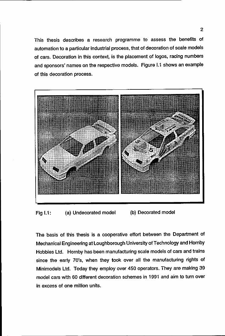
This thesis describes a research programme to assess the benefits of
automation to a particular industrial process, that of decoration of scale models
of cars. Decoration in this context, is the placement of logos, racing numbers
and sponsors' names on the respective models. Figure 1.1 shows an example
of this decoration process.
Fig 1.1: (a) Undecorated model (b) Decorated model
The basis of this thesis is a cooperative effort between the Department of
Mechanical Engineering at Loughborough University of Technology and Hornby
Hobbies Ltd. Hornby has been manufacturing scale models of cars and trains
since the early 70's, when they took over all the manufacturing rights of
Minimodels Ltd. Today they employ over 450 operators. They are making 39
model cars with 60 different decoration schemes in 1991 and aim to turn over
in excess of one million units.

3
The aim of the project is to replace a traditionally manual series of operations
by flexible automation, to provide the base for higher productivity and a greater
degree of responsiveness to product change, leading to just-in-time
manufacture with reduced work-In-progress, while still retaining the high quality
associated with the product.
It is necessary to draw the reader's attention at this early stage to the fact that
it was not intended to design and deliver an industrial system that could operate
on the factory floor straight from the laboratory. If this was the aim, then one
of the many factory automation specialist companies would have been
commissioned to carry out the work. The validity of developing such a project
in an academic environment is based upon the following:
o design options can be investigated and tested in a broader sense,
o there is time and willingness for applying novel techniques,
o off-the-shelf solutions are avoided when it is viable to do so,
o it is cheaper,
o the final result tends to be more flexible, rather than focused in
single applications.
A proof-of-concept cell has been originally designed and commissioned using
the Mechatronics approach. This means that all mechanical, electronic and
computing possibilities have been taken into account and integrated from the
first stage of the design process. The configuration of the cell consists of five
stations which provide the necessary functions for loading the bodyshells from
the moulding machine into the cell, identifying the bodyshells and their
positions, decorating and inspecting the bodyshells and finally, palletising them
for assembly.
The results of the Mechatronics approach to design and manufacture are two
fold:

4
o the efficiency of the cell is enhanced because its functions are
allocated, in an optimal fashion, to three different but integrated
technological fields, Mechanical Engineering, Electronic
Engineering and Computer Science,
o the cell can be rendered easily flexible by re-programming
facilities embedded in its components.
It is believed that this work is an original and significant contribution to
Mechatronics. It contains a proposal for a Mechatronics Design Methodology;
this was extensively used in the design of the decoration cell. As a direct result
of the application of the Mechatronics approach to deSign, a number of novel
products were developed. These were initially designed to solve a particular
problem within scale model decoration; their applications now go far beyond the
original requirement. Some of them are:
o side-lighting arrangement as an aid to computer vision systems,
o mechanical device for correcting optical illusion errors,
o robot-vision system calibration procedures,
o mechatronic robot tool changer mechanism,
o down-to-earth sequential control with embedded recovery
strategies.
All of these products are operational and currently integrated into the proof of
concept cell.
THESIS STRUCTURE
This thesis is structured in 9 chapters, excluding Introduction and Conclusion.
Each chapter begins with a structure resembling a table of contents. Its
purpose is to provide the reader at a glance with the contents and major focus
5
of the chapter. This is followed by an Introduction, which provides a context for
the topics that will be covered in the chapter and a brief summary of the issues
that will be discussed. The chapter ends with a brief Conclusion, where the
main results are reviewed and analysed.
CHAPTER CONTENTS
CHAPTER 1 reviews some of the key issues of Mechatronics. The various
definitions of the term are compared; the necessity for the existence of
Mechatronics is discussed. Examples of truly mechatronic products are
examined; Mechatronics education is also addressed.
CHAPTER 2 reviews a number of works concerning Mechatronics Design
Methodology. A new proposal is presented.
CHAPTER 3 presents the reader with a comprehensive review of the main
industrial printing techniques. Special emphasis is given to the pad printing
process, which is used by the industrial partner of this project, Hornby Hobbies
Ltd. The cooperative effort between the Department of Mechanical
Engineering, Loughborough University of Technology and Hornby Hobbies Ltd.
is reviewed.
CHAPTER 4 shows the application of the techniques presented in Chapter 2
to solve the problems discussed in Chapter 3.
CHAPTERS 5, 6 and 7 presentthe mechanical, electronic and software design
of the decoration cell, respectively. The reader is offered two routes towards
understanding the Mechatronics design of the cell: (a) going through these
chapters sequentially or (b) following the mechanical, electronic and software
design of the components of the proof of concept cell in each of the chapters.

6
CHAPTER 8 presents the operation and control of the decoration cell. These
include the start up procedure· and the recovery strategies implemented.
CHAPTER 9 details five original topics for further research which have come
out of this project and have already received considerable attention.
7
CHAPTER 1
CONCEPTS OF MECHATRONICS
CONCEPTS OF MECHATRONICS
DEFINITIONS OF MECHATRONICS
EXAMPLES OF MECHATRONIC PRODUCTS
AND SYSTEMS
THE PROFILE OF THE MECHATRONICS
ENGINEER
MECHATRONICS EDUCATION
MECHATRONICS DESIGN METHODOLOGY
9
SUMMARY
A universal definition of Mechatronics has not yet been found. Section 1.1 gives
some of the definitions in order to establish the common ground between them.
The author proposes a definition which emphasises the integrating factor of
Mechatronics and stresses the product-user interface as an area to be
enhanced by Mechatronics.
A mechatronics design ensures that the various parts of the product are
allocated between the mechanical, electronic and computing science
environments. This is shown in detail by the examples of mechatronic products
and systems given in Section 1.2.
The problem of Mechatronics education is tackled in Section 1.3. Various
national and international initiatives in this field are reviewed. Particular
emphasis is given to the Mechatronics training carried out by Japanese
companies.
Section 1.4 outlines the problem of defining an independent design approach
for Mechatronics. This subject is explored in more detail in Chapter 2.
10
1.1 DEFINITIONS OF MECHATRONICS
The definition of Mechatronics according to the EEC/R&D commission is as
follows:
"Mechatronics is the synergetic combination of precision
mechanical engineering, electronic control and systems thinking
in the design of products and processes.".
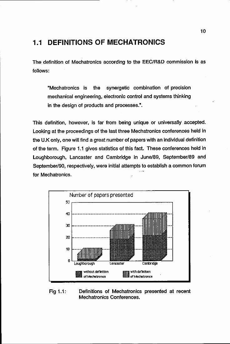
This definition, however, is far from being unique or universally accepted.
Looking at the proceedings of the last three Mechatronics conferences held in
the U.K only, one will find a great number of papers with an individual definition
of the term. Figure 1.1 gives statistics of this fact. These conferences held in
Loughborough, Lancaster and Cambridge in June/89, September/89 and
September/90, respectively, were initial attempts to establish a common forum
for Mechatronics.
Number of papers presented 5e' ,------------------,
40
30
20
10
o
Fig 1.1:
liliiii w~oout definition III of Mechatromca 11 with definition
of Mecr..tronco
Definitions of Mechatronics presented at recent Mechatronics Conferences.
11
In order to identify common points among the various definitions some of them
are shown below:
According to Hurst (1990, p. 83)
"Mechatronics is defined as a combination of electronics,
information technology and mechanics, intended to raise the
intelligence level of machines and devices and at the same time
increase their flexibility, versatility, efficiency and reliability.".
According to Preston (1990, p.17),
"Mechatronics Is a strategy which gives an appropriate integrated
combination of mechanical engineering, electronics and software
applied to development and manufacturing of a product to provide
an optimum design solution.".
According to Kajitani (1989, p.13),
"Advanced technology to create energy-saving, resource
saving and highly intelligent systems by integrating mechanics,
electronics and software is called Mechatronics.".
Despite the variations in the form of words used to express an individual
definition of Mechatronics, it is clear that its key element is the integration
through the design process of mechanical engineering, electronic engineering
and computing science.
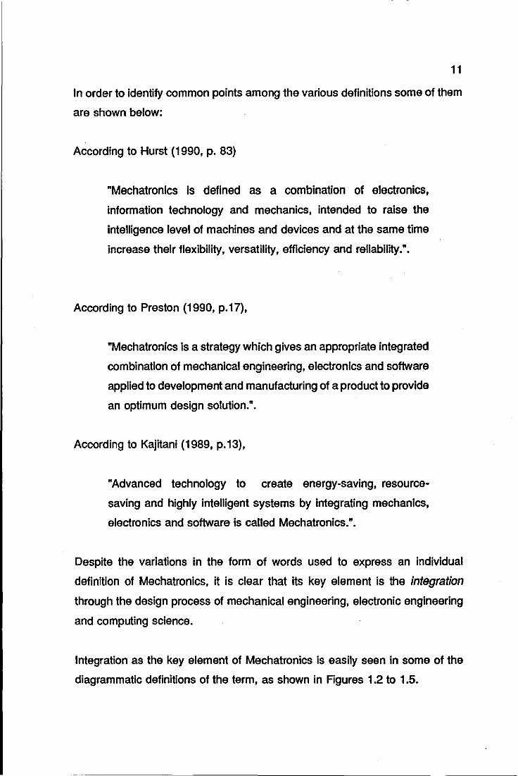
Integration as the key element of Mechatronics is easily seen in some of the
diagrammatic definitions of the term, as shown in Rgures 1.2 to 1.5.
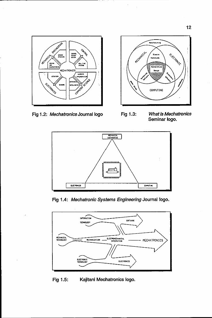
Fig 1.2: Mechatronics Journal logo Fig 1.3:
12
What is Mechatronics Seminar logo.
Fig 1.4: Mechatronic Systems Engineering Journal logo.
SCiTIIARE
PlECIWUZATlON _ELEC~~~CIJ. --- HECHATRONICS
If ____ ~---~ TEDf«X.OCY __ ----__ ~':LE:::CT:"":I:CS
Fig 1.5: Kajitanl Mechatronics logo.
13
Mechatronics, however, still remains somewhat ill understood with a wide
range of definitions placed upon it, many of which are related to and describe
functions and activities which are already being practised in a particular
industry. For example, according to Westbrook (1989, p.12), Mechatronics is
the
"Application of electronics to the control of mechanical systems",
which brings to mind a very large number of examples of applied electronic
products, which are not truly Mechatronics. Bearing in mind this definition, one
has to agree that a solenoid controlling a pneumatic valve is an example of
Mechatronics.
The problem of correctly understanding the Mechatronics concept is explicitly
shown in Garrat (1989, p.22). After describing a three axis instrument for
surface geometry measurement, he finishes his work with a question:
"Although the system design was not conceived with
Mechatronics specifically in mind, it would appear the mechatronic
route was undertaken or was it?"."
Dinsdale (1989, p.6), correctly says that "Mechatronics is one of those subjects
which has been practised for a number of years, often without the practitioners
being conscious of the name", however, this adds to the problem of defining
Mechatronics. Because of this particular view, some product designs where
electronic and mechanical components merge, perhaps by mere coincidence,
are often claimed as mechatronic designs.
The concept of Mechatronics is evidently not new, and evidence of this can be
found in many products utilising both mechanical and electronic components.
However, it does symbolise a new philosophy of product and system design.

14
A mechanical product or system which has electronic and computing
technologies as bolted on elements and not an integral part of the system or
product is not a truly mechatronic product. One can not assume that any
assembly of mechanical, electronic and computer science elements represents
a mechatronic product.
Obviously, an existing electro-mechanical system with microprocessor control
added on will have beneficial enhancements, however, the dramatic advantages
which can result from a totally integrated design, planned to use the best
properties of mechanical, electronic and computing elements will not have been
achieved.
If a product or system is to be truly mechatronic, it must be conceived from the
beginning with this aim in mind, where all the technical possibilities are
integrated into the design process from the beginning. This poses a problem
to engineers who have well established mechanical, electronic or computer
science boundaries, built by traditional Engineering education. These
boundaries have often led to Mechanical Engineers who fear transistors or
Electronic/Computer Software Engineers with no understanding of Newton's
Laws. These boundaries, increasingly artificial, have to be broken by a new
approach to Engineering Education, the Mechatronics Education, which is
detailed in Section 1.3.
Some authors believe that the sole purpose of Mechatronics is to break down
these artificial boundaries and that the time may come when the term
Mechatronics will fall into disuse because the boundaries it sought to bridge no
longer exist. /
A mechatronics design implies a continuous examination of the overall system
to determine the location of individual functions within the mechanical,
electronic or co",uting environments, making up the complete system.
15
Hewit (1989, p.24) points out some distinctive characteristics between
mechatronics and non-mechatronics designs. A non-mechatronics design tends
to be inflexible and single purpose. Where a degree of adaptability is present,
it is usually operable in steps rather than continuously. Mechatronics designs,
incorporating embedded microprocessor controls, however, can have complex
functionality, reduced size and low cost. They can be rendered easily flexible
by re-programming facilities and can operate over a wide range of parameter
values. "The only constraints to mechatronic designing are those imposed by
the boundaries of the imagination of the designer himself.".
Another interesting comment about Mechatronics is found in Preston et al , (1989, p.8), where he states that Mechatronics can be more than just the
integration of mechanical, electronic and computing technologies; "ideally", he
adds, "Mechatronics is also a mental attitude - a way of looking at problems.".
So, as well as thinking How can I solve this problem?, one asks Is there a
mechatronic solution? If there is, it is likely to have ramifications wider than the
original problem, and to offer opportunities for greater steps forward than are
possible with a more unimaginative solution.
The author would also like to express his particular views about Mechatronics.
Mechatronics design of products and systems will be referred to as:
An effective and creative design process where all mechanical,
electronic and computing possibilities are taken into account and
integrated from the first stage of the design process, in order to
achieve flexibility, efficiency, reliability and user-friendliness of
products and systems.
This concept of Mechatronics is complementary to those presented by Hurst
(1989) and Preston (1989). It was decided to propose yet another definition of
Mechatronics which would also stress the importance of the product-user
interface. Mechatronics is also a subject area which lends itself particularly
16
well to optimising the product-user interface, since a thoughtful combination of
the component subjects of Mechatronics can frequently enhance the user
friendliness of a product.
1.2 EXAMPLES OF MECHATRONIC PRODUCTS
AND SYSTEMS
The products and systems generally labelled as mechatronics are: robots,
modern cars, Ne machine tools, VTRs (\I1deo Tape Recorders), automatic
manufacturing cells, laser printers, cameras, compact disc players, ATMs
(Automatic Teller Machines).
In a typical mechatronics design, one can allocate the functions to be
performed by the parts of the product between mechanical, electronic and
computing science environments. To stress this point, four examples of
mechatronic products are presented in more detail.
1.2.1 TELESCOPE MOUNTINGS
The mounting of a telescope plays an important role in the overall design of a
telescope. Strength, rigidity and smoothness of operation must be built into the
mounting. The most common types of telescope mountings are the equatorial
and the altazimuth mountings.
An equatorial mount allows the telescope to turn to the south and to the north
about one axis and to east and to west about another. The axis for the east
west movement is parallel to the axis of the earth's rotation (called polar axis)
and the other axis is perpendicular to it. A mechanical or electric mechanism
called a clock drive is usually employed to drive the telescope automatically
about its polar axis, so that it will follow the stars accurately across the sky.
17
An altazimuth mount allows the telescope to move in two planes, vertical and
horizontal. The name altazimuth is a contraction of altitude and azimuth.
Regarding star tracking, this mounting has one great disadvantage when
compared with the equatorial mounting: it needs movement in two directions to
keep the stars in view, while the equatorial mounting needs only one. Although
the altazimuth mounting is easier to construct, needs no counterweights for
balance and is less expensive than an equatorial mounting of comparable
strength and rigidity, its tracking double movement has outweighed its
advantages. That explains the fact that nearly all astronomical optical
telescopes have equatorial mountings.
Dissenting from this trend, however, the new Willian Herschel telescope, has
an altazimuth mounting. The complexity of rotating the telescope in two
directions, rotating the image continuously by an arrangement of moving prisms
can now be accepted in order to have the structural advantages of the
altazimuth mounting, and this simple virtue justifies all the refined
microelectronics and electromechanical drives it brings with it.
1.2.2 AIRCRAFT FL Y-BY-WIRE SYSTEM
Fly-by-wire systems are generally defined as closed loop electronic systems
where the pilot's demand is sensed electronically, transmitted to a computer
which shapes and mixes the pilot demand with stabilising signals from a
motion sensor to provide composite demands to an electrically signalled
actuation system. In the case of aircraft the actuation system drives control
surfaces to close the loop aerodynamically.
Although not new in concept, a complete re-development of the system was
deemed to be necessary in recent years as a means of controlling some highly
sophisticated types of aircraft coming into service. The problem associated with
such aircraft has been one of designing conventional forms of mechanical
linkage to suit the complex flight control systems adopted. Thus, a fly-by-wire
18
system, as the name very aptly suggests, is one in which wires carrying
electrical signals from the pilot's controls, replace mechanical linkages entirely.
The benefits of this control system are enhanced in gusts and manoeuvres,
where the load on the wings of an aircraft increases. By adjusting the control
surfaces, this temporary high loading can be reduced, so that the wing can be
made lighter and more load can be carried, or the wing can be made longer,
which improves fuel economy and range, or some combination of these and
other desirable changes can be achieved.
As a further advance in the fly-by-wire concept, systems utilising fibre-optic
cables for conveying flight commands, fly-by-light systems, have been
developed. The principal advantage of this method is its immunity to
electromagnetic interference, and the consequent elimination of the heavy
shielding required to protect the more conventional signal wires.
1.2.3 THE AUTOFOCUS CAMERA
A number of means have been devised to focus the lens for the user, involving
distance measurement (triangulation or ranging techniques) or sharpness
measurements or both. In the first successful commercial autofocus cameras,
the focusing drivers were crude, often resulting in bulky lens structures. Some
of them were simply a solenoid aided by a spring.
Nowadays, ultrasonic motors using piezo-electric actuators have been
developed to drive the focusing mechanism under the control of the lens and
body microprocessors. The result of locating these motors in the body of the
camera is a very compact lens structure, which is then integrated with the
operation of the camera by means of the lens and body microprocessor
systems.
19
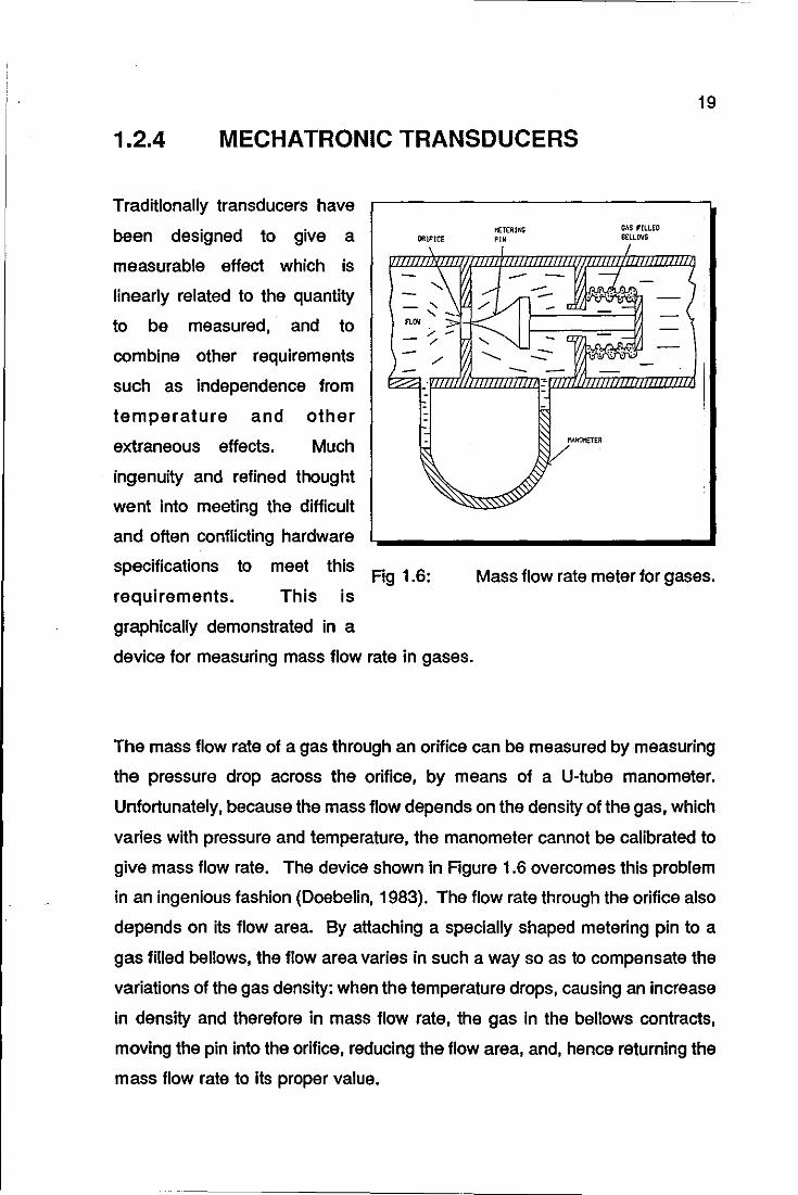
1.2.4 MECHATRONIC TRANSDUCERS
Traditionally transducers have
been designed to give a
measurable effect which is
linearly related to the quantity
to be measured, and to
combine other requirements
such as independence from
temperature and other
extraneous effects. Much
ingenuity and refined thought
went into meeting the difficult
and often conflicting hardware
specifications to meet this
requirements. This is
graphically demonstrated in a
ORIFICE
\
- ~\ --'- -FLOV ;,- -- / - ,/
~-~ ----
Fig 1.6:
device for measuring mass flow rate in gases.
I'fETEAING G~S flLLEO
'" BilloWS
-- - .::1. - (
--1 --.- . ,,' . ;: - • y _ a _'o~
-( ~
-- 0 --= I;~'.", --- --- 10. ~ 0 --- - -
: m --
<::;:;VIfOHETER
Mass flow rate meter for gases.
The mass flow rate of a gas through an orifice can be measured by measuring
the pressure drop across the orifice, by means of a U-tube manometer.
Unfortunately, because the mass flow depends on the density of the gas, which
varies with pressure and temperature, the manometer cannot be calibrated to
give mass flow rate. The device shown in Figure 1.6 overcomes this problem
in an ingenious fashion (Doebelin, 1983). The flow rate through the orifice also
depends on its flow area. By attaching a specially shaped metering pin to a
gas filled bellows, the flow area varies in such a way so as to compensate the
variations of the gas density: when the temperature drops, causing an increase
in density and therefore in mass flow rate, the gas In the bellows contracts,
moving the pin into the orifice, reducing the flow area, and, hence returning the
mass flow rate to its proper value.
20
Nowadays, linearity, temperature independence, accuracy and other features
can be provided by microelectronics, enabling the performance to be improved
and the cost to be reduced. In this example, a look-up table with the values of
gas density at various temperatures and pressures would enable the unit to be
calibrated very quickly and accurately by software.
The potential for mechatronics applications is enormous. It is believed that the
success of Mechatronics will be further achieved if two fundamental problems
are resolved: the education of mechatronics engineers and the establishment
of a truly mechatronics design methodology. These items are discussed below.
1.3 THE PROFILE OF THE MECHATRONICS
ENGINEER
An engineer, or a group of engineers, who are now designing mechatronic
products and systems, are, according to French (1989), resourceful engineers
who have mostly been brought up in some traditional discipline and who have
picked up sufficient of their colleagues' expertise to secure a knowledgable
coordination effort.
These engineers can not be regarded as true mechatronic engineers though.
Dinsdale (1989, p.6), describes the ~true mechatronic engineer~ as being an
individual whose interests and abilities lie in working across disciplinary
boundaries to identify and use the particular blend of technologies which will
provide the most economic, elegant and appropriate solution to the problem in
hand. The mechatronic engineer would also be a high communicator with the
aptitude of being able to interest others in technologies outside their own, and
hence to break down resistance to the use of alternative approaches.
--------------------- ------ -- -----
21
The necessity of specialised mechatronic education seems to be evident.
However, the need to examine all technical possibilities in the design process,
from its first stage, poses a contradiction and a challenge to mechatronic
education: on the one hand, as rapid technological advances are made,
engineers and scientists are becoming more highly specialised in narrower
fields. On the other hand, there is a recognised requirement for a broad range
of multi-disciplinary knowledge to be applied at early stages in the design
process of mechatronic products and systems. The various approaches to
solve the mechatronics education and its apparent contradiction are shown
below:
1.3.1 THE JAPANESE WAY
Even though it was first introduced into Japan more than 10 years ago
Mechatronics is not yet formally taught in the majority of the Japanese
universities. Actually, only one university, Toyohashi University of Technology,
runs a regular ME course in Mechatronics. The view of Japanese
educationalists is that the mechatronics engineer is essentially a mechanical
engineer, whose education has been broadened to include knowledge and skills
in microprocessor hardware and software, electronics, actuators and control.
The fact that in Japan engineers and designers are in effect, employed for life
explains the apparent lack of enthusiasm of the Japanese for a formal
mechatronics education at University level.
Japanese companies, according to a Professor at Toyohashi University,
assume that "the young engineer is not well educated and he will stay in the
company all his life.". The companies are then eager to educate their
employees continuously, without fear of losing their investment.
The training systems of Japanese companies aim to produce generalists which
partially solves the contradiction of mechatronic education, pointed out above.
22
The generalist approach makes the work force flexible and also conforms to the
ideals of Japanese society, which does not readily accept individuals striving
to rise above the average.
The companies' training consists of courses on technology and working skills,
including design exercises and a job rotation schedule of 1-2 department
changes every year (Burr, 1990). The company also makes sure that every
engineer has personal experience in the sales and manufacturing departments.
This training process can last up to 5 years, before the engineer is given the
opportunity to work independently.
1.3.2 THE NORTH·AMERICAN WAY
. The name Mechatronics is hardly used in U.S.A and there are no formal
courses at any level specifically titled with this name.
"Unfortunately", explains Hunt (1988, p. 14), "Mechatronics is still sometimes
viewed as something to be left for the factory floor engineer, outside the
academic world.". Mechatronics education, when present, is strongly linked to
robotic applications. Recently, the Centre of Robotic Systems, at the University
of California has received a substantial grant to establish the National Centre
of Robotic Systems in Microelectronics, which is regarded, according to Hunt,
as "one of the prime examples of Mechatronics education in the United
States.".
1.3.3 THE EUROPEAN WAY
The Europeans firmly believe that a formal education in Mechatronics at
university level is necessary (Trabasso et ai, 1991 a). The first university to run
a postgraduate course in Mechatronics was the Catholic University of Leuven,
in Belgium, in 1986. This initiative was quickly followed by universities in the
23
Netherlands, Denmark, Germany, Finland, Sweden, Ireland, Switzerland and
Great Britain.
One important characteristic of the European approach to mechatronics
education is the close relationship between universities and industry. This is
frequently presented as a common project stimulated by government funds.
In Finland, for instance, there was a three year mechatronic research
programme (1987-1990), involving four universities, the Technical Research
Centre of Finland and a number of industries. As a direct result of such a
program, Mechatronics was formally included in the educational curriculum of
an MSc degree at Helsinki University of Technology. Short courses for industry
are also provided.
In the Netherlands, the government funding in 1989 has led to the
establishment of the Mechatronics Research Centre Twente, at the University
of Twente, which coordinates the mechatronic activities between the university
and industrial partners.
The Department of Mechanical Engineering of the Royal Institute of
Technology, Sweden, has a four and a half year course leading to an MSc
degree in Mechatronics. According to Hanson (1990), the first two years of the
course are concentrated on basic engineering. In the next two years, though,
the students are offered 16 diversified avenues to choose from. The avenue
that leads to the Mechatronics degree is Micro-computer system design for
embedded systems, where the motivation for the students is created by the
challenge of solving a real industrial problem. A working prototype is always
requested. Hanson claims that over 90% of the graduate students are now
working in the Swedish MechanicaVElectrical industry in activities related to
Mechatronics.
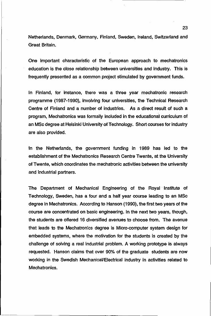
At Zuric·h University,
Switzerland, a one year
postgraduate course in
Mechatronics has been regularly
offered since 1987. The
disciplines of this course are
shown in Figure 1.7. Parts of
this postgraduate course are
presently being incorporated
into the regular Undergraduate
Curricula in Mechatronics.
The Mechatronics group which
runs this course is formed by
•
• • • • • • • •
24
Computer . Aided Kinematics and Kinetics of Mechanisms.
Computer Vision.
Robust and Adaptative Control.
Optimal filters.
~croprocessors.
Applied Artificial Intelligence.
Electrical Drive Systems.
Robotics.
~crotechniques.
• Real time data processing.
• Masters thesis.
members from the Mechanical, Fig 1.7: Zurich University Mechatronics subjects
Electronic and Computer
Science departments of the university.
In Germany (IFW Institute, Hanover) and in Ireland (University College Dublin),
the mechatronics activities are focused onto production and manufacturing
engineering, and specifically how it applies to small companies.
Before addressing mechatronics education at British universities, it is worth
mentioning the genuine initiative taken by the British government via the
Department of Trade and Industry: the Mechatronics Awareness Programme.
This initiative, according to Keyworth (1989), aims to reduce the phase lag
between the provision of a sufficient number of suitably qualified new or re
trained mechatronics engineers and technicians. This programme includes
mechatronic training courses at both technician and graduate levels and the
MBDS (Aifechatronics Bus Demonstration System). The MBDS is a mobile
mechatronics demonstration unit which models an automated factory from
CAD/CAM design through raw material preparation, robotic handling, CNC
25
machining and an in progress and final product inspection using computer
vision. In June/1989 more than 150 presentations were given in both the UK
and Europe.
1.3.3.1 MECHATRONICS AT BRITISH UNIVERSITIES
A four year Mechatronics MEng course at Lancaster University was the first
such course to be established in the UK. The structure of the course is similar
to that adopted in Sweden: students of all courses share a common 2 year
basic engineering unit. From the third year onwards, students who choose the
Mechatronics option are offered subjects such as robotics, manufacturing
systems, integrated circuit design, power electronics and management studies,
with the option of biasing their studies towards either Electronic Engineering or
Mechanical Engineering, as they wish. The industrial links are, according to
Bradleyand Dawson (1990), also an active part of the course.
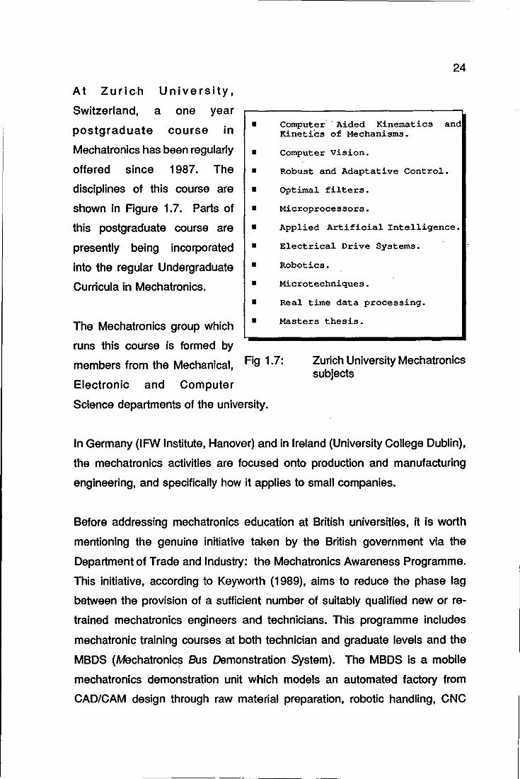
The Department of Electronic
Engineering at the University of Hull
offers an MSc course in
Mechatronics which is structured in a
modular manner. This structure aims
to suit a wide range of entrants;
those with first degrees in
mathematics, computer science and
the physical sciences are sought, as
well as those from a more traditional
engineering background. The course
comprises six modules, as shown in
• •
•
•
• •
Design for Mechatronics.
Logic Circuits and Microprocessor applications
Mechatronic Systemmode~ling and Simulation.
Control Systems
of Mechatronic
Sensors and actuators.
Manufacturing Engineering.
Systems
Fig 1.8: University of Hull Mechatronics modules.
Figure 1.8. The final weeks of the course involves an industrial placement with
one of the collaborating companies, working on a mechatronics project.
26
Scotland, identified by its Silicon Glen and base for various mechatronics types
of industries has not as yet a formal Mechatronics course. At Dundee Institute
of Technology a well equipped Mechatronics Laboratory will be the base for the
imminent introduction of a structured Mechatronics course. The Glasgow
College mechanical-electronic BEng degree "is believed", explains Taylor
(1990, p.272), "to be a suitable mechatronics degree, because of its total
product design core.".
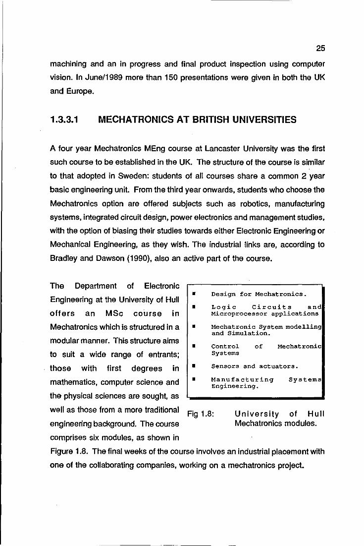
The Department of Mechanical
Engineering at Loughborough
University of Technology offers
a one year MSc course in
Mechatronics blended with
Optical Engineering. According
to Prof. Hewit, Head of the
Department, "Optical
Engineering may also need to
• • • • • • •
Mechanisms and Robotics a
Microprocessor applications.
Optical methods in Engineering.
Machine systems.
Opto-Mechatronics.
Electronics and Control.
Design and Manufacture of Mechatronic Products.
be considered right from the Fig 1.9: Loughborough University Mechatronics modules.
concept stage of design,
because of the increasing
application of optoelectronics and laser technology to a wide range of consumer
products and capital plant.". The first part of the course consists of formal
teaching of the subjects shown in Figure 1.9 and the second part is reserved
for an individual project, "with an emphasis on working towards solutions of real
industrial problems", according-to the course brochure.
It is evident that the Japanese way of tacking the problem of Mechatronics
education is very effective; one has only to examine the current ranges of
Japanese robots, video recorders, cameras, laser printers, compact disc
players and computer peripherals to visualize the success of their approach.
27
The Europeans of course, can not duplicate the Japanese approach for a
number of reasons. Perhaps the most important of these is how the European
industry is structured; the engineers and designers are not life time employees
and this certainly causes the industry to refrain from investing massively in
training, unlike the case in Japan. The responsibility of Mechatronicseducation
is then left to the Universities, Research Centres and the European
governments. There seems to be no doubt that the European Mechatronic
Engineer is capable of matching his Japanese counterpart in terms of span of
knowledge.
The main challenge is to match the team spirit of the Japanese industry, where
fully integrated teams of product deSigners work with manufacturing, purchasing
and marketing personnel to design a product. The team spirit of the Japanese
companies comes from cultural and environmental reasons. The cultural
reason is expressed by the close relationship between the employees and the
company and by the Japanese taste for equality: a manager at Toshiba
Corporation describes the Japanese company like "a family: everybody does
what he can for the best of the company, and the company takes care of you.".
Also, one company union includes all the employees with no differentiation as
to skills or job category, adds Burr (1990).
The environmental reason is expressed by the physical surroundings of the
project team: the way the engineers are located in relation to each other, office
layout, available facilities, etc. The large and open space offices with common
document files are unique to Japanese companies. This peculiar office layout,
according to Burr,
• fosters working discipline, as everybody in the group can watch
everybody else and also contributes for the unity of the group.

28
• facilitates the spreading of information in an informal and
effective fashion. By overhearing telephone calls, overlooking
colleagues's drawings, the information is quickly shared
throughout all the group members.
• boosts creativity, that comes from inspiration provided by
communication and close contacts with fellow workers.
• improves project documentation handling: the office has a public
filing system. The documentation itself benefits from this, so much
so that the contributors tend to document activities more carefully,
because the document must be readable by everybody in the
team.
If the environmental reasons presented above to explain the Japanese attitude
can somehow be implemented by European industry, that could just be enough
to boost the team spirit, a vital factor in Mechatronics. However something else
appears to be necessary: the attitude towards cooperation within industry.
Perhaps the Japanese take this for granted and the Europeans will have to use
their imagination and creativity to foster it in their industries if they want the
Mechatronics industry to be a success.
1.4 MECHATRONICS DESIGN METHODOLOGY
Proven design methodologies for Mechanical Engineering, Electric/Electronic
Engineering and Software Engineering are well established and currently
available. Shigley (1986), Texas Instruments (1984) and Wirth (1976), present
individual contributions for each area, respectively.
Conversely, the mechatronics design methodology is an area of intense
research, with no definitive solution yet. The researchers in this field are trying
29
to blend, in the best possible way, concepts developed in each of the individual
component areas of Mechatronics.
Burr (1989) emphasizes that the design of mechatronic products imposes
difficulties, mainly because:
• the substance of design problems is different in the three fields
encompassed by Mechatronics,
• a common language for mechanical, electronic and software
designers does not exist,
• the bridge between the education of mechanical, electronic and
software engineers has not yet been built.
Because this present work brings a personal contribution in this field, the
problem of the mechatronic design methodology is presented in a chapter of
its own: the up-to-date procedures are reviewed and a new approach is
presented in detail.
----------------- --------------
30
CONCLUSION
Even though a large number of individual definitions is placed upon
Mechatronics, its key element, the integration through the design process of
Mechanical Engineering, Electronic Engineering and Computer Science, can be
easily identified.
The striking feature of Mechatronics is the freedom that it gives to the designer
to allocate a particular function of the product between three different
technological fields.
Japan is showing the world beyond any doubt that Mechatronics is a clear path
to industrial success. Massive investment is made by Japanese industry in
Mechatronics education. Although investment in Mechatronics education poses
a severe problem to Western industries, the real challenge, is to find an
effective way to match the Japanese team spirit, which seems to be the key
factor to their industrial success.
31
CHAPTER 2
MECHATRONICS DESIGN
METHODOLOGY
MECHATRONICS DESIGN METHODOLOGY
METHODOLOGY VERSUS CREATIVITY IN
THE DESIGN ACTIVITY
UP-TO-DATE REVIEW OF MECHATRONICS
DESIGN AIDS AND METHODOLOGIES
DEFINITION OF MECHATRONICS DESIGN
MECHATRONICS DESIGN TEAM
THE LUT MECHATRONICS DESIGN TEAM
PHASES OF MECHATRONICS DESIGN
METHODOLOGY
33
SUMMARY
The purpose of this chapter is to outline the design methodology utilised for the
design of the proof-of-concept cell, which is the physical embodiment of this
dissertation, designated from now on as the decoration cell.
This methodology possesses two key features: a mechatronics design team
and a phased mechatronics design process. The former is intended to
overcome the !ack of a common language between mechanical, electronic and
computer software designers; the latter is a variation of the known and
accepted phases of engineering design activity, adapted accordingly to suit
Mechatronics. The very definition of Mechatronics, briefly reviewed in Section
2.3, seems to indicate the validity of this approach.
The author has no intention of proposing the foundations for a comprehensive
Mechatronics design methodology; he simply describes the methodology
applied to the design of the decoration cell. Eventually, some of the guidelines
introduced could indeed become the first steps towards such a methodology;
it is not the scope of this chapter, however, to investigate such a possibility.
The purpose of any design methodology should be to aid the designer with the
systematic steps of the design activity, for example, how to choose a solution
from a set of possible alternatives according to some criteria. However, even
the best design methodology will never replace the creativity required from a
designer. This point is further emphasised in Section 2.1.
34
2.1 METHODOLOGY VERSUS CREATIVITY IN THE
DESIGN ACTIVITY
Engineering practice is undergoing a profound change, just as society at large
has been transforming, due to the advent of computers. Clearly computers are
having a significant impact in the design field: graphic representation of design
concepts, simulation of design embodiments, rapid generation of hard copies
with all the specific details of a design, vast data storage and manipulation and
integration of design and manufacturing. Various expert systems and other
artificial intelligence based programs have been developed using ad hoc design
rules. These programs are used in VLSI circuit design, assembly and other
applications. Most of these programs are rule-based interactive software
programs, where the design answers are arrived at through a series of queries.
Because computers are becoming increasingly powerful and faster, some
people believe that one day computers will have built-In intelligence, being
creative and capable of making their own decisions. Some people do not
believe this. The arguments for justifying both positions are endless.
The author believes that the creativity required from a designer can never be
supplanted by any methodological approach supplied by computers or
otherwise. The possibility of a non-creative designer, even if aided by a
powerful computerised design methodology, creating a very good design seems
to be remote. Besides, computers have serious limitations and will continue to
do so. One fundamental limitation is given by Bremmerman's limit,
(Bremmerman, 1983). He concludes that a hypothetical computer the size of
the entire Earth could not deal with more than 270 variables at a time. In many
design situations, the total number of variables involved may be larger than
270.
35
Design methodologies, however, do play a very important role In the design
activity, as they allow the designer to organise his ideas, to explore alternative
solutions, to preview design results, and, to some extent, to boost the creative
process. The design methodologies have to be seen as aids to the design
activity, and not as substitutes to creativity.
2.2 UP-TO-DATE REVIEW OF MECHATRONICS
DESIGN AIDS AND METHODOLOGIES
Mechatronics design methodology is an area of intense research, with no
definitive solution yet. The most recent contributions in this field are reviewed
below.
2.2.1 MECHATRONICS SCHEME BUILDER
French (1990) proposes the concept of function-costing as an aid to
mechatronic design. Far from being a comprehensive mechatronlc design
methodology, this tool would provide target costs at the specification stage of
the design process, resolving, therefore, choices between alternative means to
achieve the design specifications.
This aid, termed mechatronic scheme builder, is intended to save the designer
a great deal of time whilst he is selecting the means that might be used to
perform the design functions and, at the same time, to provide a record of the
ground explored. Described very briefly, the mechatronic scheme-builder is a
general purpose table of options, requiring the specification of inpuVoutput
connections, and the aSSignment of values to various parameters to define an
outline of a viable solution to the design problem and to provide, via function
costing, an estimated cost of each alternative. It is an augmentation of the
Mechanical Design Compiler of Ward and Seering (1989), which intends to
36
encompass the three technological areas of Mechatronics.
2.2.2 MECHANICAL SOFTWARE GENERATOR
Buur (1989) tackles the problem of describing the overall functional structure
of a mechatronic product Independently of any technological realisation. The
major obstacle in creating such a structure would be the description of the
mechanical functions in terms of logical relations. He proposes a mechanical
software tool for overcoming this problem. By using this tool. the usual
mechanical functional structures like flow and transformation of material. energy
and information would be replaced by logical relations of the type 11. •• then ....
thus compatible with the functional structure of computer software and
electronics.
This definition of the overall functional structure of a mechatronic product is the
first stage of the concept deSign process. This is followed by two more stages:
technological principles are assigned to the functions in the second stage and
in stage three the design may be split into specific design models for
mechanics. electronics and software.
2.2.3 COMMON LANGUAGE OF MECHATRONICS
Salminen and Verho (1989) add to the body of opinion among researchers
which claims that a common language of Mechatronics is essential. This
language would allow mechanical. electronic and computer software designers
to discuss openly the various problems of mechatronic product design. They.
however. go beyond the recognition of the need of such a language and
propose what can be called a draft. This language would have three levels:
• Symbolic language for required functions: language for
determining the functions the customer needs.
2.2.4
37
• Conceptual phase language: language for the problem definition
and conceptual design phases,
• Expert phase language: expert language for embodiment and
detailed design phases.
THE COMMON GROUND OF DESIGN IN
DIVERSE DOMAINS
Although Stauffer (1989) is not primarily concerned with mechatronic design
methodology, he sums up the results of a survey carried out among mechanical
engineers, architects and computer software engineers, which reveal the
common ground and the main differences of the design activity of these three
areas.
Stauffer asserts that the designers in each domain have developed methods
of their own for solving the well structured problems1 they encounter. But for
the ill structured problems2, they use the same general approach: identify and
acquire problem information, generate a solution, test it, and maybe verify and
document that solution. They also share the same problem-solution methods,
the weak methods3• This suggests that the designers in diverse domains solve
problems with the same techniques at some higher level. The content of their
problems, though, causes the application of these techniques at a detailed level
to differ. These differences apply mainly to the items being designed and their
1
2
3
Those usually solved by analytical and determdnistic methods, e.g., vibrational modes of a structure, maximum speed of an engine, etc.
Those whose structure lacks definition. There is initially no known way to test a proposed solution an no known way to arrive at a solution.
Problem solving methods based upon the search paradigm. The main methods are: generate-and-test, Monte-Carlo, hill climbing, heuristic search and induction.
38
constraints rather than the way they are designed. For example, mechanical
designers are concerned about manufacturing whereas software designers
never need to think about it.
This review corroborates the fact that a comprehensive Mechatronics design
methodology is yet to be defined. The reviewed works only partially answer
some of the well known problems of mechatronic design. Moreover, the
presented solutions are not substantiated by practical applications. This has
encouraged the author to formulate the Mechatronics design methodology
described in this chapter, as an aid to the design of the decoration cell.
2.3 MECHATRONICS DESIGN DEFINITION
"Mechatronics is the synergetic combination of precision
mechanical engineering, electronic control and systems thinking
in the design of products and processes.".
This definition of Mechatronics according to EEC/R&D commission implies that
the Mechatronics design activity is an enhancement of the engineering design
process as it enlarges the domain of possible solutions for a particular problem.
It was also said in Chapter 1 that a mere assembly of mechanical, electronic
and computer science elements does not represent a truly mechatronic product.
Similarly, to simply assemble mechanical, electronic and computer software
design methodologies will not yield a mechatronic design methodology. The
two main reasons are:
• the essence of design problems is different in the three
technological areas of Mechatronics, that is, the design problems
differ in terms of functions to be realised, types of solution
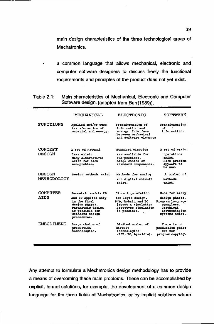
available, computer aids and so forth. Table 2.1 summarises the
39
main design characteristics of the three technological areas of
Mechatronics.
• a common language that allows mechanical, electronic and
computer software designers to discuss freely the functional
requirements and principles of the product does not yet exist.
Table 2.1: Main characteristics of Mechanical, Electronic and Computer Software design. (adapted from Burr(1989)}.
FUNCTIONS
CONCEPT DESIGN
DESIGN METHODOLOGY
COMPUTER AIDS
EMBODIMENT
MECHANICAL
Applied and/or pure transformation of material and energy.
A set of natural law8 exist. Many alternatives exist for each 8ub-problem.
Design methods exist.
Geometric models 20
and 3D applied only in the final design phaaes. Parametric design i. possible for standard design procedures.
Large choice of production technologies.
ELECTRONIC SOFTWARE
Transformation of Transformation information and of energy. Interface information. between mechanical and software elements.
standard circuits
are available for sub-problems. Large choice of standard component ••
Methods for analog
and digital circuit exist.
Circuit generation
for logic design. PCB, hybrid and lC layout , simulation Prototype simulation is possible. .
Limited number of circuit technologies (PCB, lC, hybrid' 8) .
A aet of basic
operations exist. Each problem appear. to be new.
A n\lDlbe;r of
method. exist.
None for early d.sign pha8es.
Program language compilers. Graphical documentation
8Y8tems .Xi8t.
'rhere is no production pha ••
but for program. copying.
Any attempt to formulate a Mechatronics design methodology has to provide
a means of overcoming these main problems. These can be accomplished by
explicit, formal solutions, for example, the development of a common design
language for the three fields of Mechatronics, or by implicit solutions where
40
such a common language is, for instance, embedded in the design team. The
former will lead to a general, designer independent methodology and the latter
to a restricted, designer dependent methodology.
The author presents a Mechatronics design methodology based upon the latter
alternative, to be applied to the design of the decoration cell. This
methodology focuses on two key features: the mechatronic designer and the
phases of the Mechatronics design activity. This Mechatronics design
methodology means not only the sequence of steps to be followed in order to
produce a mechatronlc product, but also the way a mechatronic design team
executes these steps. This section starts by justifying the need of a
Mechatronics design team as opposed to a single mechatronic designer,
followed by the mechatronic design steps, conveniently adapted from the
general engineering design process.
2.4 THE MECHATRONICS DESIGN TEAM
In their work on Integrated Product Development, Andreasen and Hein (1987)
describe the ideal company as one in which a single person is in charge, and
where knowledge of the market, design, production and economic mechanisms
are collected together in one person, who is also able to make decisions and
is willing to take risks. The reality however, shows companies divided into
departments, such is the demand for specialisation, the necessary division of
labour and so on.
A clear parallel can be made between the Mechatronics designer and the ideal
company. It is unlikely that one person would have the necessary level of
knowledge of the three technological areas of Mechatronics to produce a good
mechatronlcs design. It is reasonable to think in terms of a team of designers
Instead, who, between them, could cover the various aspects of the
Mechatronics design. Again the parallel between a team of designers and the
41
departments of a company seems to be pertinent.
It was said that a common language that allows designers of mechanics,
electronics and software to discuss freely the functional requirements and
principles of the product does not yet exist. Andreasen and Hein experienced
a similar situation, when they were trying to find an integrated product
development language within a company divided into departments, with well
defined boundaries. They stressed the fact that to bring together
representatives of a number of departments around the Product Development
table was not the way to solve the problem. Keeping the analogy, to gather
Mechanical, Electronic and Computer Science Engineers around the
Mechatronics Design table Is not the way of solving the problem either.
Forming a team is not just a matter of putting together people who are
specialists in different areas. Each specialist has his own way of thinking, his
own frame of reference and uses his own special vocabulary which sometimes
is almost impossible to be understood by outsiders. Moreover, the possibilities
for design modelling, existing design methodologies and computer aids vary
greatly among the three technological fields. This mechatronics team can be
labelled a non-blended mechatronics team.
Bearing in mind the results of Stauffer's work reviewed in Section 2.2.4, one
could infer that a non-blended mechatronics team would produce acceptable
results at some stages of the design process, where ill defined problems were
present. However, such a team would start facing serious difficulties at phases
requiring technology integration, e.g., that of defining the overall functional
structure of a mechatronic product. By contrast, in a blended mechatronics
team, the members are able to appreciate and understand their co-workers and
are also able and willing to work in a team fashion. The mechatronics design
language that allows the team members to understand one another is
embedded in the team formation.
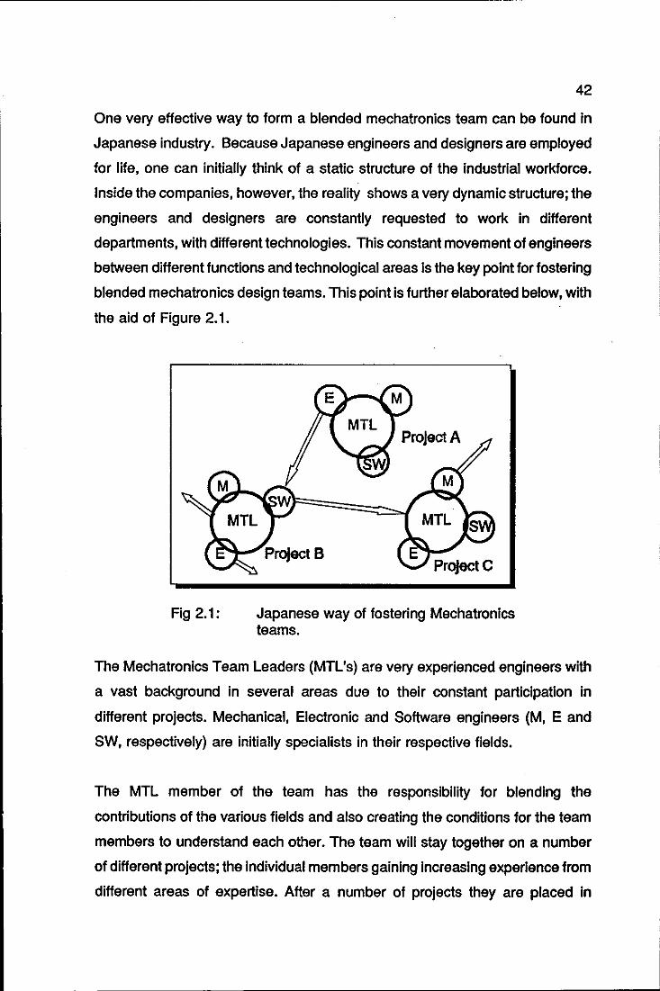
42
One very effective way to form a blended mechatronics team can be found in
Japanese industry. Because Japanese engineers and designers are employed
for life, one can initially think of a static structure of the industrial workforce.
Inside the companies, however, the reality shows a very dynamic structure; the
engineers and designers are constantly requested to work in different
departments, with different technologies. This constant movement of engineers
between different functions and technological areas is the key point for fostering
blended mechatronics design teams. This point is further elaborated below, with
the aid of Figure 2.1.
Fig 2.1:
ProJect A
Japanese way of fostering Mechatronics teams.
The Mechatronics Team Leaders (MTL's) are very experienced engineers with
a vast background in several areas due to their constant participation in
different projects. Mechanical, Electronic and Software engineers (M, E and
SW, respectively) are initially specialists in their respective fields.
The MTL member of the team has the responsibility for blending the
contributions of the various fields and also creating the conditions for the team
members to understand each other. The team will stay together on a number
of different projects; the individual members gaining Increasing experience from
different areas of expertise. After a number of projects they are placed in
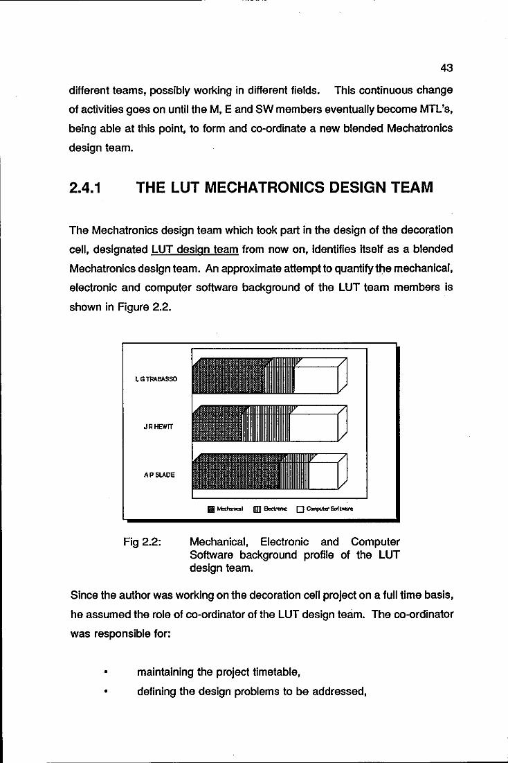
43
different teams, possibly working in different fields. This continuous change
of activities goes on until the M, E and SW members eventually become MTL's,
being able at this point, to form and co-ordinate a new blended Mechatronics
design team.
2.4.1 THE LUT MECHATRONICS DESIGN TEAM
The Mechatronics design team which took part in the design of the decoration
cell, designated LUT design team from now on, identifies itself as a blended
Mechatronics design team. An approximate attempt to quantify the mechanical,
electronic and computer software background of the LUT team members is
shown in Figure 2.2.
LGTRABASSO
JRHEWrT
AP SLADE
Fig 2.2: Mechanical, Electronic and Computer Software background profile of the LUT design team.
Since the author was working on the decoration cell project on a full time basis,
he assumed the role of co-ordinator of the LUT design team. The co-ordinator
was responsible for:
• maintaining the project timetable,
• defining the design problems to be addressed,
44
• convening in the design team whenever necessary,
• supervising the overall structure of the decoration cell as new
components were linked to it,
• assessing regularly the integration of the various components of
the cell.
In this particular project the LUT team was joined from time to time by the
members listed below. The name of the members is followed by the area in
which the cooperative effort was concentrated.
• Hornby Hobbles Ltd: printing techniques. The LUT team visited
Hornby factory many times in order to define correctly the
problem of automatic decoration. Hornby provided the necessary
information on the subject as well as decoration hardware,
ranging from body-shells, inking plates, pads and a Tampo pad
printing machine.
• Joyce-Loebl Ltd, supplier of the MX vision system: computer
vision software.
• BVG, supplier of the software package GRASP: off-line
programming and simulation.
• University of Aberdeen: robot object-level programming
language RAPT.
• Stliubli/Unimatlon, supplier of the robot PUMA: mechanical
support.
• Conferences: general comments about the ideas shown in the
presented papers.
45
• Visitors to the laboratory facilities: general comments about
mechanical and software components of the cell.
• Research visitors: specific contribution in areas of mutual
interest. For example, Dr. Cezary Zielinski from the Warsaw
University of Technology had an active participation on the
development of the vision & robot interface software.
2.5 PHASES OF THE MECHATRONICS DESIGN
PROCESS
The sequence of events that take place in an engineering design activity is well
known, Shigley (1986) and Dieter (1983). It is reasonable to expected that this
sequence of events also applies to a mechatronics design process, as
mechatronics design is an enhancement of the general engineering design
activity. Obviously, the substance of the events has to be adapted accordingly
from the general to the mechatronics design. Figure 2.3 shows the sequence
of events in the Mechatronics design activity.
The Mechatronics design process, as in any design activity, begins with the
recognition of a need and a decision to do something about it. This need is
formalised, resulting in a set of functional requirements and design constraints
which defines the mechatronics design problem. Once the need is formalised,
ideas are generated to create a product or an organisational structure. This
product is then analysed and compared with the original set of functional
requirements through a feedback loop. If the product does not fully satisfy the
specified functional requirements and design constraints, then the deSigner
must either come up with a new idea, or change the functional requirements to
reflect the original need more accurately. This iterative process continues until
the designer produces an acceptable product.

46
-4 REca;NITKJN OF THE NEED I
RJNCTDW.. t ~lJFIe.errs --=-t DESGN REQUIREMENTS' .-I
resr.:;N t PARAMETRES
I t--SYNTHESIS
t '-- --i ANALYSIS AND OPTI>AlSATKJN
+ I EVALUATKJN t-I
+ I PRESENTATON I
Fig 2.3: The phases of Mechatronics design.
Evaluation is the next phase of mechatronics design, the final proof of a
successful design. It usually involves the testing of a prototype in laboratory
and/or field trials. Finally, in the presentation phase, the designer creates
information in the form of drawings, specifications, tolerances, circuits, flow
charts, equations and other relevant knowledge required to create the physical
entity. The relevant aspects of the phases of the mechatronics design are
further elaborated below:
2.5.1 RECOGNITION OF THE NEED
Irrespective of whether a mechatronics design is based oil radically new ideas
or will merely make a small improvement to an existing product, the sole reason
for the design activity is that it must meet a recognised need. The need is
sometimes not evident at all; in this case, its recognition is usually triggered by
a particular adverse circumstance. For example, the need to set the tension of
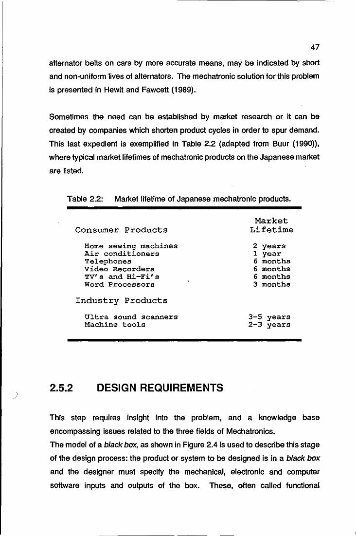
47
alternator belts on cars by more accurate means, may be indicated by short
and non-uniform lives of alternators. The mechatronic solution for this problem
is presented in Hewit and Fawcett (1989).
Sometimes the need can be established by market research or it can be
created by companies which shorten product cycles in order to spur demand.
This last expedient is exemplified in Table 2.2 (adapted from Buur (1990»,
where typical market lifetimes of mechatronic products on the Japanese market
are listed.
Table 2.2: Market lifetime of Japanese mechatronic products.
2.5.2
Consumer Products
Home sewing machines Air conditioners Telephones Video Recorders TV's and Hi-Fi's Word Processors
Industry Products
Ultra sound scanners Machine tools
DESIGN REQUIREMENTS
Market Lifetime
2 years 1 year 6 months 6 months 6 months 3 months
3-5 years 2-3 years
This step requires insight into the problem, and a knowledge base
encompassing issues related to the three fields of Mechatronics.
The model of a black box, as shown in Figure 2.4 is used to describe this stage
of the design process: the product or system to be designed is in a black box
and the designer must specify the mechanical, electronic and computer
software inputs and outputs of the box. These, often called functional
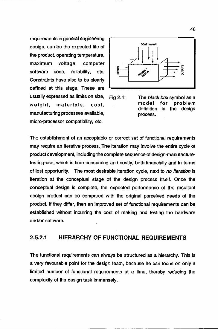
requirements in general engineering
design, can be the expected life of
the product, operating temperature,
maximum voltage, computer
software code, reliability, etc.
Constraints have also to be clearly
defined at this stage. These are
.7 ---.:::.
-
usually expressed as limits on size, Fig 2.4:
weight, materials, cost,
manufacturing processes available,
micro-processor compatibility, etc.
48
CON&11WNTS
/' < 4.;
i/
The black box symbol as a model for problem definition in the design process.
The establishment of an acceptable or correct set of functional requirements
may require an iterative process. The iteration may involve the entire cycle of
product development, including the complete sequence of design-manufacture
testing-use, which is time consuming and costly, both financially and In terms
of lost opportunity. The most desirable iteration cycle, next to no iteration is
iteration at the conceptual stage of the design process itself. Once the
conceptual design is complete, the expected performance of the resultant
design product can be compared with the original perceived needs of the
product. If they differ, then an improved set of functional requirements can be
established without incurring the cost of making and testing the hardware
and/or software.
2.5.2.1 HIERARCHY OF FUNCTIONAL REQUIREMENTS
The functional requirements can always be structured as a hierarchy. This is
a very favourable point for the design team, because he can focus on only a
limited number of functional requirements at a time, thereby reducing the
complexity of the design task immensely.
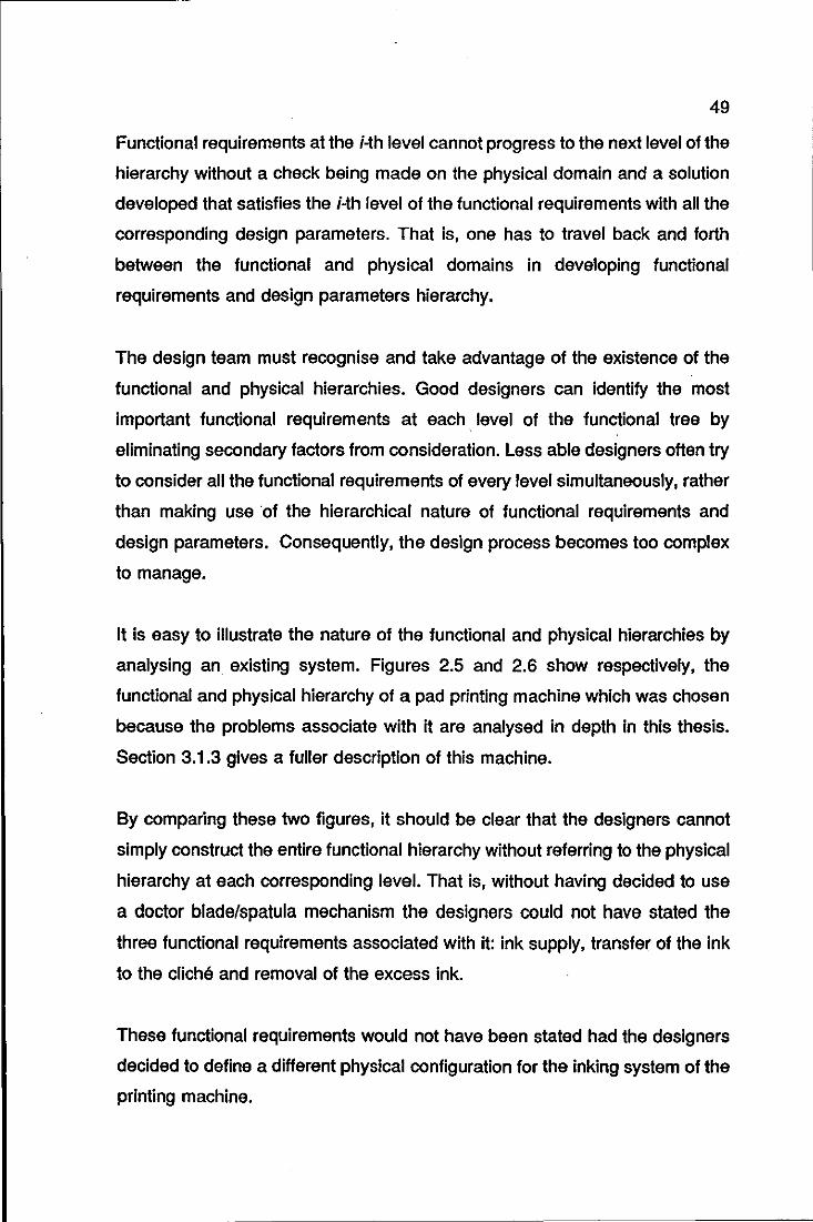
49
Functional requirements at the i-th level cannot progress to the next level of the
hierarchy without a check being made on the physical domain and a solution
developed that satisfies the i-th level of the functional requirements with all the
corresponding design parameters. That is, one has to travel back and forth
between the functional and physical domains in developing functional
requirements and design parameters hierarchy.
The design team must recognise and take advantage of the existence of the
functional and physical hierarchies. Good designers can identify the most
Important functional requirements at each .. level of the functional tree by
eliminating secondary factors from consideration. Less able designers often try
to consider all the functional requirements of every level simultaneously, rather
than making use of the hierarchical nature of functional requirements and
design parameters. Consequently, the design process becomes too complex
to manage.
It is easy to illustrate the nature of the functional and physical hierarchies by
analysing an existing system. Figures 2.5 and 2.6 show respectively, the
functional and physical hierarchy of a pad printing machine which was chosen
because the problems associate with it are analysed in depth in this thesis.
Section 3.1.3 gives a fuller description of this machine.
By comparing these two figures, it should be clear that the designers cannot
simply construct the entire functional hierarchy without referring to the physical
hierarchy at each corresponding level. That is, without having decided to use
a doctor blade/spatula mechanism the designers could not have stated the
three functional requirements associated with it: ink supply, transfer of the ink
to the cliche and removal of the excess ink.
These functional requirements would not have been stated had the designers
decided to define a different physical configuration for the inking system of the
printing machine.
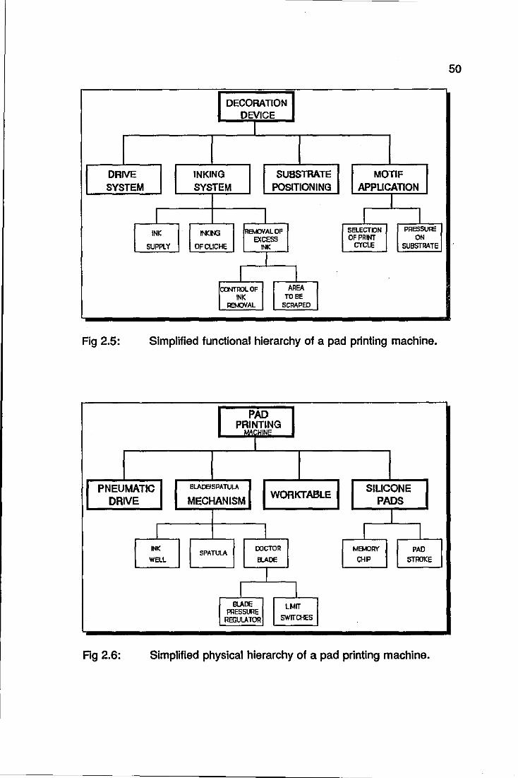
50
DECORATION DEVICE
I
DRIVE INKING SUBSTRATE MOTIF SYSTEM SYSTEM POSITIONING APPLICATION
I I I I
INK INCIIG REM:lVALOF SELECTDN PRESSure
EXCESS OF PRINT ON SUPPLY OF CLICHE INK CYCLE SU8STRATE
CQNTROLOF AREA INK TO BE
REMOVAL SCRAPED
Fig 2.5: Simplified functional hierarchy of a pad printing machine.
PAD PRINTING
I
PNEUMATIC BLAOEISPATULA SILICONE DRIVE MECHANISM
WORKTABLE PADS
I I I INK
SPATUlA OOCTOR MEIoORY PAO
WELL BLADE CHP STROKE
L BLAOE LMIT
PRESSURE REGUlATOR SWIT01ES
Fig 2.6: Simplified physical hierarchy of a pad printing machine.
51
2.5.3 SYNTHESIS
The third step in the design process is the creative process of synthesizing a
design solution in the form of physical embodiment. This is a highly subjective
process. The creative ideas and the synthesis process depend upon the
specific knowledge possessed by the designers team, and on their ability to
integrate this knowledge. This is normally a quality expected from a designer
working in any engineering design area; for a mechatronics designer however,
it is a mandatory requirement.
Much work has been done to understand the creative process and develop
systematic approaches to assist it, Asimow (1962), Buhl (1962), Fasal (1965)
and Zwicky (1948). For example, Harrisberger (1966) lists the following
techniques which can be used to aid the synthesis process:
• Trigger-work technique.
• Checklist technique.
• Morphological technique.
• Attribute-seeking technique.
• Brainstorming technique.
Many authors present rules for product synthesis in various situations, viz.
Glegg (1960) and Woodson (1966), as well as general methodologies, Alger
and Hayes (1964) and Ostrotsky (1977). In addition to these, synthesis rules
that can be used during assembly have recently been developed by Boothroyd
(1987). Many software packages have also been created to assist the
designer, Daizhong and Forgie (1989) and Black and Murray (1989). Finally,
the utility function method has been widely used as a mathematical tool for
decision making. These techniques are either algorithmiC, which apply rules
or classification methods to a specific situation, e.g., Boothroyd, Buhl and Glegg
or they cannot be generalised.
2.5.3.1
52
THE EXPERIENCE OF THE LUT TEAM ON PRODUCT
SYNTHESIS
The brainstorming technique was extensively used by the LUT design team.
As a background for such sessions, the team co-ordinator would brief the team
with the design problem and the first draft of its functional requirements.
Is there another way of achieving the same result? What will happen if
component A is replaced by component B? Is this output compatible with the
other components? These are examples of questions frequently asked in
those sessions, in order to guarantee that all possible technological options
were explored, as there is a natural tendency of the designers to be initially led
by mechanical answers to the problem. This is explained by the fact that it is
the physical realisation of a solution that first catches the imagination of the
designers.
2.5.4 ANAL VSIS AND OPTIMISATION
The creative process cannot be very effective without the use of assessment
tools to judge whether the product performance complies with the functional
requirements of the product.
The Important role played by an assessment tool as a way to evaluate the
product design is illustrated by the design of steam engines in the nineteenth
century. In those days the axioms of thermodynamics were not established and
designers therefore had to try many different ideas without the benefits of
thermodynamics. Each inventor developed various engines by trial and error,
and claimed that these engines were better than the rest. There was no way
of distinguishing the advantages of one design over another without actually
building the system and testing it.

53
This chaotic method for developing energy-conversion devices might have
persisted to this day had it not been for the conceptual contributions made by
Carnot and Joule during the latter part of the nineteenth century. They
proposed the underlying fundamental processes involved in steam engines.
These thermodynamics principles, formalised by Clausius, are the first and
second laws of thermodynamics, which can now be derived from the equilibrium
axiom. These principles established the concept of energy and entropy in a
fundamental base, and provided the tools with which to eliminate perpetual
motion machines from consideration at design stage. They also enabled the
designer to compute the theoretical limits and efficiencies of proposed energy
systems. These laws largely eliminated fruitless arguments over the merits of
many energy conversion devices through the establishment of a theoretical
base.
In the absence of principles or axioms that could be used as absolute
foundations or references, the synthesis activity depends upon analogy,
imitation, experience, extrapolation, interpolation and sub-optimisation
processes.
In some cases the fundamental principles do exist, but are hardly used or
known by the designers. This has indeed been the case in Computer Science
where, the scientific foundations are very well established, e.g., 800le's algebra
and semantics of artificial languages, but are usually not appreciated and used
by the programmers as a guide during the synthesis process that forms the
bulk of computer science work. As an immediate consequence, the immense
amount of labour required in writing software can be attributed directly to the
perSistence of the programmers not to use these scientific principles.
Unfortunately, some would argue that such principles are very difficult to
understand and utilise, anyway.
One of the most recent attempts to provide the design activity with scientific
basis is proposed by Suh (1990). He explores the fact that there are features
54
or attributes which distinguish between good and bad designs and argues that
the common elements associated with the features of a good design might form
the basis for developing a unified theory for the synthesis process. He finally
proposes two axioms that might govern good design:
Axiom 1
Axiom 2
The independence axiom
Maintain the independence of the functional requirements of the
producVsystem to be designed.
The information axiom
Minimise the information content of the design.
Two Equations are proposed to verify whether a design satisfies the axioms;
for the first axiom the design equation, Equation 2.1, is proposed. It
characterizes the mapping process between the functional and physical
domains.
{FR} = [A].{DP} (2.1)
where {FR} is the functional requirement vector, {DP} is the design parameter
vector, and [A] is the design matrix. The simplest case of a design which
satisfies Axiom 1 occurs when all the non-diagonal elements of the matrix [A]
are zero. According to Suh, this is an ideal, uncoupled design. From the
second axiom, the equation for quantifying information associated with the
functional requirements is proposed, Equation 2.2. It is based on the fact that
the notion of information is closely related to the probability of achieving a
functional requirement.
I = log2(range/tolerance) (2.2)
where I is the information content, the ratio range/tolerance defines the
probability of successfully achieving the functional requirement.
2.5.4.1
55
THE EXPERIENCE OF THE LUT TEAM ON
PRODUCT ANALYSIS AND OPTIMISATION
The iterative cycle synthesis-analysis-optimisation at the concept stage
assumed different forms in the decoration cell design:
a) VERY SHORT CYCLE: immediately after a brainstorming
session, the LUT design team would go to the laboratory facilities
in order to assess the suitability of the ideas, having in that
instance, the physical framework in view.
b) SHORT CYCLE: used where some form of analytical analyses
were required, sometimes carried out by indirect means. For
example, the analytical criterion for selecting the best lighting
apparatus was the value of the confidence level resulting from the
vision classification routines. The design axioms proposed by Suh
were applied in some instances. Quick mock-ups were also used
whenever they were easy to build.
c) LONG CYCLE: in this iterative cycle, the LUT team used to be
Joined by some of the external members referred to in Section
2.3.1. The way this cycle was implemented is shown in Figure
2.7: a conceptual design would be exposed to a number of
external opinions, judgements and comments; the useful
information was gathered and then fed-back to the LUT team.
The open characteristic of this project allowed for the
improvement of some design concepts based, in some instances,
upon comments of visitors to the laboratory facilities. This
external feedback information could be used at the conceptual
stage of the design. For some components however, this would
happen in the physical embodiment phase.
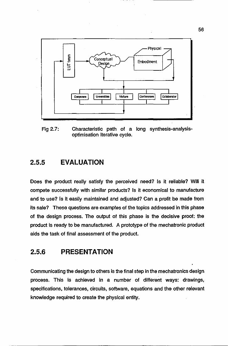
Fig 2.7:
2.5.5
Physical
Errbodlment
Characteristic path of a long synthesis-analysisoptimisation iterative cycle.
EVALUATION
56
Does the product really satisfy the perceived need? Is it reliable? Will it
compete successfully with similar products? Is it economical to manufacture
and to use? Is it easily maintained and adjusted? Can a profit be made from
its sale? These questions are examples of the topics addressed in this phase
of the design process. The output of this phase is the decisive proof: the
product is ready to be manufactured. A prototype of the mechatronic product
aids the task of final assessment of the product.
2.5.6 PRESENTATION
Communicating the design to others is the final step in the mechatronics design
process. This is achieved in a number of different ways: drawings,
specifications, tolerances, circuits, software, equations and the other relevant
knowledge required to create the physical entity.
57
CONCLUSION
The initial goal of this project was to provide an alternative, automated
approach to the problem of decorating scale models of cars. This goal was later
extended to be not only an automated but also a mechatronics approach to the
problem.
The first challenge for this latter goal was to find an appropriate design
methodology to suit Mechatronics. Many authors argue that such a
methodology does not exist yet, and indicate the main problems to be
overcome before it can possibly be brought into being.
This chapter has presented the Mechatronics design methodology used in the
design of the decoration cell. It was not intended to be a general mechatronics
design methodology nor to replace the creativity of the designers. This
methodology depends upon the characteristic of the problem, whether open or
restricted, and also relies upon the profile of the design team.
However specific, this methodology has proved to be useful in bringing
together engineers who have not worked together before and blending their
individual creative flairs in designing the decoration cell. This will become
clear in the Chapter 4.

58
CHAPTER 3
INDUSTRIAL DECORATION
PROCESSES
INDUSTRIAL DECORATION
PROCESSES
DECORATION PROCESSES FOR PLASTICS
PAD PRINTING
SPRAY PAINTING
SCREEN PRINTING
HOT STAMPING
INK JET PRINTING
HORNBY HOBBIES L TO
FROM 1952 TO THE PRESENT
LOOKING TO THE FUTURE
DECORATION PROCESSES CURRENTLY
USED
LOUGHBOROUGH UNIVERSITY & HORNBY
HOBBIES LTD. COOPERATIVE EFFORT

60
SUMMARY
This chapter briefly reviews some of the various industrial printing techniques.
This review aims to give the reader a background for answering questions
concerning the feasibility and suitability of application of a technique in a
particular instance. Special emphasis is given to the pad printing process,
which is used by the industrial partner of this project, Hornby Hobbies Ltd.
The second part of the chapter focuses on Hornby Hobbies Ltd. This starts with
a quick chronological review of the company, explains why it is now seeking
advanced production methods and finally stresses the problems found in their
decoration processes.
The chapter finishes with a review of the cooperative effort between the
Department of Mechanical Engineering, Loughborough University of Technology
and Hornby Hobbies Ltd., which has led to the realisation of this thesis.
The author has explicit authorisation from Hornby Hobbies Ltd. for mentioning
the name of the company, describing their industrial processes related to this
work and showing photographs of their products and machinery.
61
3.1 DECORATION PROCESSES FOR PLASTICS
Surface appearance is an item of growing importance in manufacturing.
Frequently, it is this that sells the product. Sometimes the required surface
appearance can be achieved during fabrication of the product, but often,
additional operations are required to change the surface in order to satisfy the
aesthetic or functional product requirements.
Product surfaces can therefore, be painted, printed, metallized, embossed, or
polished. These finishing operations, although secondary in importance, can
amount to a significant part of the total cost of the product.
While finishing operations can be applied to a vast number of different
materials, this section only describes decoration and finishing processes applied
to plastics 1, because this is the material used to manufacture scale model cars.
The following plastic decoration processes are described: pad printing, spray
painting, screen printing and hot stamping.
Pad printing is detailed in greater depth, because it is the main decoration
process currently being used by the industrial partner of this project and also,
it is the decoration technique which this work is based upon. Ink jet printing
Is also briefly described given its future, potential application in the decoration
of scale models.
3.1.1 PAD PRINTING
Pad printing is basically an offset gravure printing method. The ink is applied
in excess over an engraved plate, a blade removes the excess, a soft silicone
1 short for Acroylonitrite Butadiene Styrene (ABS).
62
rubber pad picks up the ink from the engraved plate and transfers it to the
surface to be printed.
3.1.1.1 ORIGINS OF PAD PRINTING
The origins of the pad printing process are found in the European watch
industry, two hundred years ago, (Stinton, 1974). This method was originally
used in the Swiss watch industry for decorating watch faces. In those days, the
watch faces were hand painted with ornate designs.
One of the artists involved in this task had the idea of making a positive
engraving of his dial design in a metal plate. Covering the plate with ink and
removing the excess of ink with a blade in a scraping movement, the ink stayed
only in the engraved area. The ink in the engraving was transferred or lifted
to the clock face by pressing a gelatine pad onto the engraved picture and then
pressing the pad onto the watch face.
The main advantage of the new printing process was that by using a finely
engraved plate (or cliche), very fine and detailed printing could be achieved,
since the gelatine pad transferred exactly what it picked up. The main
disadvantage of the process, however, was that the life of the gelatine pad was
very short, the material subject to heat changes, attack by ink, and general
wear. Normally, the gelatine pads had to be daily re-moulded and stored in
refrigerators.
In Germany, according to Grob (1987), the industrialist Wilfried Philip saw the
potential of the pad process throughout other sectors of industry where complex
surfaces and inaccessible print areas were constantly giving rise to problems
in operation and finish. Although he greatly contributed to the automation of
the process, his major contribution was the solution to the problems associated
with the gelatine pad. He invented a new formula for the pad material, based
on a silicone rubber compound, plasticized with silicone oils. In 1968 he
63
founded the company Tampoprint which produced the first automatic pad
printing machines for large scale industrial applications.
3.1.1.2 PAD PRINTING TODAY
The pad printing process presently competes successfully with printing
techniques such as screen printing, hot stamping, offset printing and mask
spraying in decorative applications.
Today as much as 90% of the decoration in the interior of a car is applied by
pad printing, states Grob. It is still the principal printing technique used in the
watch industry. Pad printing can impress characters onto a completely
assembled plastic keyboard in one stroke; it can print decorative design directly
onto compact discs; it can impart decorations on plastic beverage bottle
closures at fast assembly-line rates.
Pad printing can be applied to flat, cylindrical or odd-shaped parts, using either
one or more colours. In multiple colour printing, the wet-on-wet technique is
used, without drying time between colour applications. These are claimed to
be its main advantages when compared to the other printing processes.
3.1.1.3 CURRENT PAD PRINTING MACHINES
A large variety of types and sizes of pad-printing machines is currently
available, ranging from small, hand operated models to huge configurations
hydraulically driven. The smallest printers normally employ printing plates that
are 5 by 5 centimetres in area. The largest machines have printing plates that
measure 90 by 40 centimetres.
Pad-printing machines can be set up for single or multi-colour printing and can
incorporate various types of indexing tables, shuttle devices, linear and rotary
conveyors.
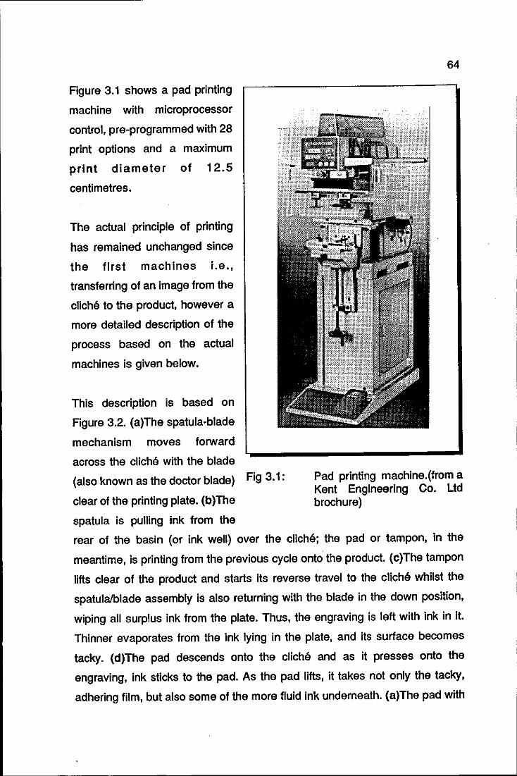
Figure 3.1 shows a pad printing
machine with microprocessor
control, pre-programmed with 28
print options and a maximum
print diameter of 12.5
centimetres.
The actual principle of printing
has remained unchanged since
the first machines i.e.,
transferring of an image from the
cliche to the product, however a
more detailed description of the
process based on the actual
machines is given below.
This description is based on
Figure 3.2. (a)The spatula-blade
mechanism moves forward
across the cliche with the blade
(also known as the doctor blade) Fig 3.1:
clear of the printing plate. (b)The
spatula is pulling ink from the
64
Pad printing machlne.(from a Kent Engineering Co. Ltd brochure)
rear of the basin (or ink well) over the cliche; the pad or tampon, in the
meantime, is printing from the previous cycle onto the product. (c)The tampon
lifts clear of the product and starts its reverse travel to the cliche whilst the
spatulalblade assembly is also returning with the blade in the down position,
wiping all surplus ink from the plate. Thus, the engraving is left with ink in it.
Thinner evaporates from the ink lying in the plate, and its .surface becomes
tacky. (d)The pad descends onto the cliche and as it presses onto the
engraving, ink sticks to the pad. As the pad lifts, it takes not only the tacky,
adhering film, but also some of the more fluid ink underneath. (a)The pad with
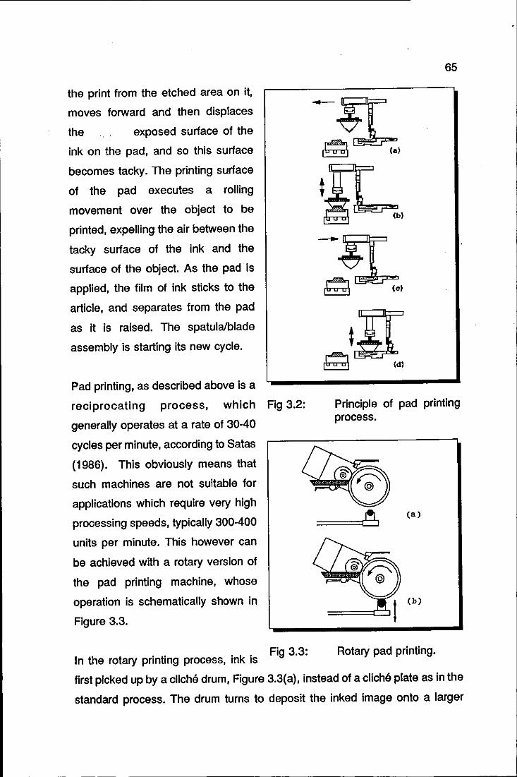
the print from the etched area on it,
moves forward and then displaces
the exposed surface of the
ink on the pad, and so this surface
becomes tacky. The printing surface
of the pad executes a rolling
movement over the object to be
printed, expelling the air between the
tacky surface of the ink and the
surface of the object. As the pad is
applied, the film of ink sticks to the
article, and separates from the pad
as it is raised. The spatula/blade
assembly is starting its new cycle.
Pad printing, as described above is a
reCiprocating process, which Fig 3.2:
generally operates at a rate of 30-40
cycles per minute, according to Satas
(1986). This obviously means that
such machines are not suitable for
applications which require very high
processing speeds, typically 300-400
units per minute. This however can
be achieved with a rotary version of
the pad printing machine, whose
operation is schematically shown in
Figure 3.3.
I h . . . k' Fig 3.3:
n t e rotary pnntlng process, In IS
65
(bl
Principle of pad printing process.
(a)
(b)
Rotary pad printing.
first picked up by a clicM drum, Figure 3.3(a), instead of a cliche plate as in the
standard process. The drum turns to deposit the inked image onto a larger
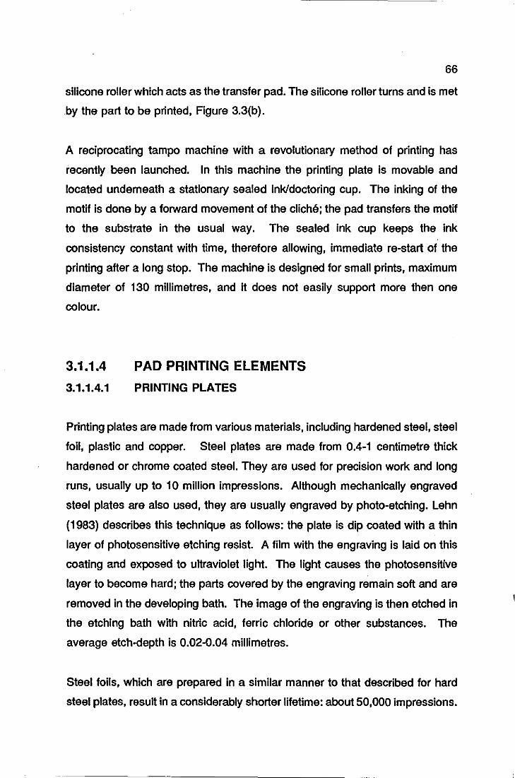
66
silicone roller which acts as the transfer pad. The silicone roller turns and is met
by the part to be printed, Figure 3.3(b).
A reciprocating tampo machine with a revolutionary method of printing has
recently been launched. In this machine the printing plate is movable and
located underneath a stationary sealed ink/doctoring cup. The inking of the
motif is done by a forward movement of the cliche; the pad transfers the motif
to the substrate in the usual way. The sealed ink cup keeps the ink
consistency constant with time, therefore allowing, immediate re-start of the
printing after a long stop. The machine is designed for small prints, maximum
diameter of 130 millimetres, and it does not easily support more then one
colour.
3.1.1.4
3.1.1.4.1
PAD PRINTING ELEMENTS
PRINTING PLATES
Printing plates are made from various materials, including hardened steel, steel
foil, plastic and copper. Steel plates are made from 0.4-1 centimetre thick
hardened or chrome coated steel. They are used for preCision work and long
runs, usually up to 10 million impressions. Although mechanically engraved
steel plates are also used, they are usually engraved by photo-etching. Lehn
(1983) describes this technique as follows: the plate is dip coated with a thin
layer of photosensitive etching resist. A film with the engraving is laid on this
coating and exposed to ultraviolet light. The light causes the photosensitive
layer to become hard; the parts covered by the engraving remain soft and are
removed in the developing bath. The image of the engraving is then etched in
the etching bath with nitric acid, ferric chloride or other substances. The
average etch-depth is 0.02-0.04 millimetres.
Steel foils, which are prepared in a similar manner to that described for hard
steel plates, result in a considerably shorter lifetime: about 50,000 impressions.
67
Copper plates can be an inexpensive alternative for short runs. However,
because copper is softer than steel, it requires a deeper etch and, as result, as
Rogers (1979) points out, makes the ink harder to control in printing, it dries
more slowly, tends to blur and ultimately does not produce such clear or
accurate images as steel plates.
Also for short runs, nylon or photopolymer plates can be used. These are
produced from a metal backing plate coated with a photosensitive layer, which
polymerises under the action of light, and so becomes hard. The etching
process that follows is similar to that described for steel plates. Treated
carefully, these plates can produce up to 20,000 impressions.
3.1.1.4.2 PADS
The pad is manufactured from silicone rubber plasticized with silicone oils.
They are made by pouring formulated silicone compound into the mould and
curing. The cured pad is mounted on a plywood block. The pad shape
depends upon the surface to be printed. Several standard shapes are
available; some are shown in Figure 3.4.
The pad shown In Figure 3.4(a) is often used for printing simple surfaces,
achieving a good roll-off effect, minimising the possibility of air entrapment
above the ink. Usually, the pad is compressed during the printing until the side
walls are almost vertical. Figure 3.4(b) shows a doughnut shaped pad for
printing dials which have a raised knob in the centre. For printing long and
narrow areas2, the pad shown in Figure 3.4(c) is the most appropriate. Finally,
Figure 3.4(d) shows a ribbon pad for applying ink to the bottom of a slot.
2 typically 5 x 20 centimetres.
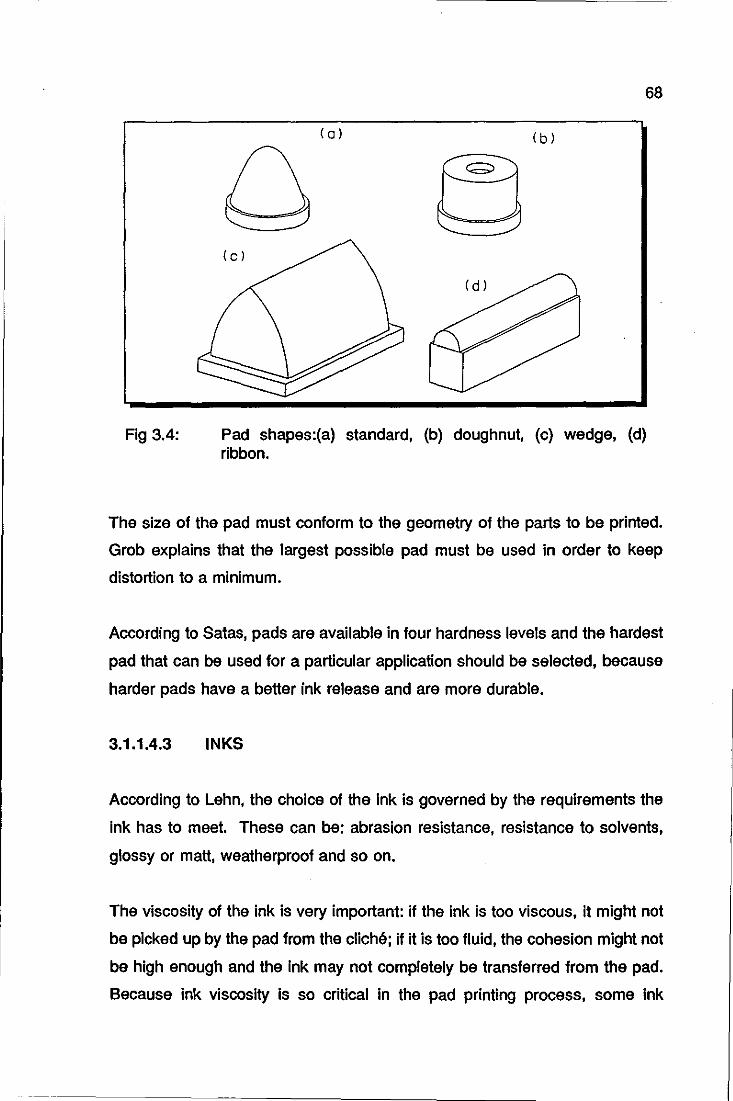
Fig 3.4:
68
( a ) (b)
(c)
Pad shapes:(a) standard, (b) doughnut, (c) wedge, (d) ribbon.
The size of the pad must conform to the geometry of the parts to be printed.
Grob explains that the largest possible pad must be used in order to keep
distortion to a minimum.
According to Satas, pads are available in four hardness levels and the hardest
pad that can be used for a particular application should be selected, because
harder pads have a better ink release and are more durable.
3.1.1.4.3 INKS
According to Lehn, the choice of the ink is governed by the requirements the
ink has to meet. These can be: abrasion resistance, resistance to solvents,
glossy or matt, weatherproof and so on.
The viscosity of the ink is very important: if the ink is too viscous, it might not
be picked up by the pad from the cliche; if it is too fluid, the cohesion might not
be high enough and the ink may not completely be transferred from the pad.
Because ink viscosity is so critical in the pad printing process, some ink
69
suppliers developed simple viscosity meters that can be used when the printing
machine is operating.
3.1.1.5 APPLICATIONS
The range of applicaticons for pad printing is limited only by the size of the
image. Because it can be used on irregular surfaces and on wet-on-wet
operations, pad printing is widely accepted for printing computer components
and electrical appliances. Pad printing is also used for medical devices,
automotive parts, glass frames and lenses, sporting goods, toys, watch and
Instrument dials, Irregularly shaped containers, advertising speclalties, cigarette
lighters, pens and many other products.
3.1.2 SPRAY PAINTING
Spray painting is the most widely used of all the plastic decoration methods.
Practically all plastics can be decorated via this method, moulded and solid
extruded parts, in single or multiple colours.
Spray painting can be anything from simple hand spraying to a highly
automated system with very elaborate masks for multiple-colour decoration and
automatic cleaning facilities. The action of automatic equipment, for the most
part, duplicates what a person would do by hand.
The spray painting equipment consists of a spray gun and, depending upon the
application, masks and drying units. The spray gun is the heart of spray
painting. Various types of spray gun actions are available:
rotary guns: two guns are usually mounted in a spray unit and
they rotate around the part to be painted.
70
reciprocating guns: these have a back-and-forth spray action
and the guns may travel on a curved traverse to paint the sides
of complicated parts
spindle machines: parts rotate on spindles, guns are stationary
and can paint from the top and bottom at the same time. This
technique is generally used on small parts and is in widespread
use in the toy industry.
combined motion: examples of this action are rotating guns and
reciprocating parts or rotating parts and reciprocating guns.
Two basic types of guns are available to deliver the paint: air and airless. The
basic function of an air atomizing gun is to use compressed air to break up the
paint or other coating into small droplets and direct them towards the part to be
sprayed. The mix of air and coating can take place inside, internal mix nozzle,
or outside, external mix atomisation. Airless spraying does not require the
direct use of compressed air to atomize the coating. Hydraulic pressure is
used to atomize the fluid.
If an all-over spray is not needed, shielding masks are required. These masks
are made to conform directly to the part's surface and can be as simple as
paper and tape to vacuum formed materials or electroformed metal masks.
One of the major problems with any type of mask is cleaning. How this is done
has an important bearing on the production rate. This can be done manually,
by using a solvent tank wash or automatically, by using high pressure water,
detergents and solvents. The effect of an integrated system which
incorporates cleaning facilities can increase the production rate by as much as
100%, according to Trauemlcht (1969), but also, it doubles the cost of the
machinery. Finally for some spraying applications, the use of drying ovens is
necessary.
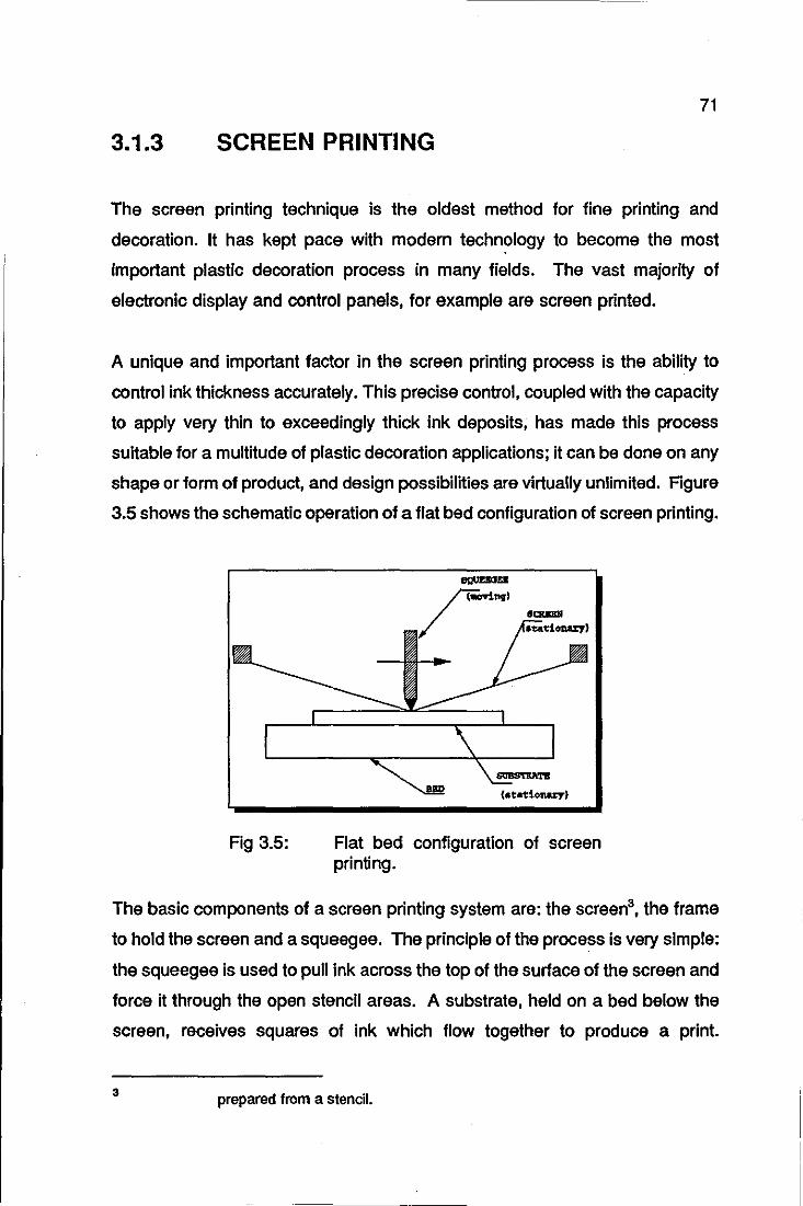
71
3.1.3 SCREEN PRINTING
The screen printing technique is the oldest method for fine printing and
decoration. It has kept pace with modern technology to become the most
important plastic decoration process in many fields. The vast majority of
electronic display and control panels, for example are screen printed.
A unique and important factor in the screen printing process is the ability to
control ink thickness accurately. This precise control, coupled with the capacity
to apply very thin to exceedingly thick ink deposits, has made this process
suitable for a multitude of plastic decoration applications; it can be done on any
shape or form of product, and design possibilities are virtually unlimited. Figure
3.5 shows the schematic operation of a flat bed configuration of screen printing.
Fig 3.5: Flat bed configuration of screen printing.
The basic components of a screen printing system are: the screen3, the frame
to hold the screen and a squeegee. The principle of the process is very simple:
the squeegee is used to pull ink across the top of the surface of the screen and
force it through the open stencil areas. A substrate, held on a bed below the
screen, receives squares of ink which flow together to produce a print.
3 prepared from a stencil.
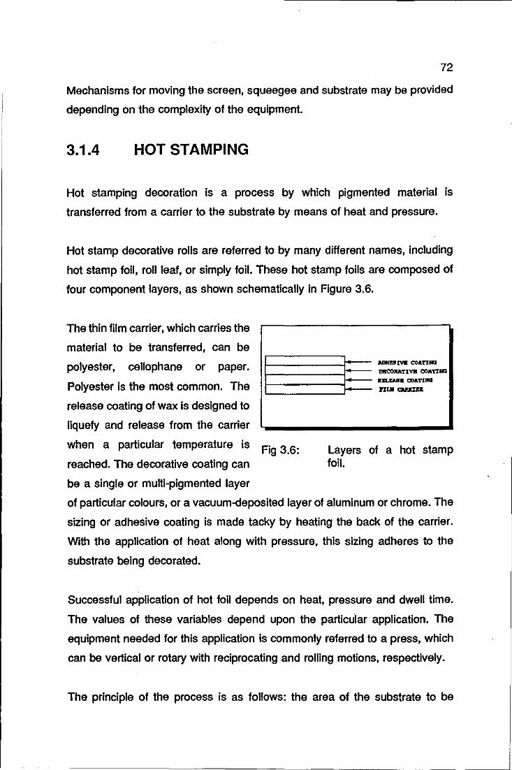
72
Mechanisms for moving the screen, squeegee and substrate may be provided
depending on the complexity of the equipment.
3.1.4 HOT STAMPING
Hot stamping decoration is a process by which pigmented material is
transferred from a carrier to the substrate by means of heat and pressure.
Hot stamp decorative rolls are referred to by many different names, including
hot stamp foil, roll leaf, or simply foil. These hot stamp foils are composed of
four component layers, as shown schematically in Figure 3.6.
The thin film carrier, which carries the
material to be transferred, can be
polyester, cellophane or paper.
Polyester is the most common. The
release coating of wax is designed to
liquefy and release from the carrier
when a particular temperature is
reached. The decorative coating can
be a single or multi-pigmented layer
Fig 3.6: Layers of a hot stamp foil.
of particular colours, or a vacuum-deposited layer of aluminum or chrome. The
sizing or adhesive coating is made tacky by heating the back of the carrier.
With the application of heat along with pressure, this sizing adheres to the
substrate being decorated.
Successful application of hot foil depends on heat, pressure and dwell time.
The values of these variables depend upon the particular application. The
equipment needed for this application is commonly referred to a press, which
can be vertical or rotary with reciprocating and rolling motions, respectively.
The principle of the process is as follows: the area of the substrate to be
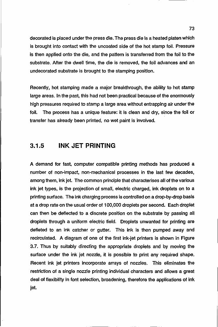
73
decorated is placed under the press die. The press die is a heated platen which
is brought into contact with the uncoated side of the hot stamp foil. Pressure
is then applied onto the die, and the pattern is transferred from the foil to the
substrate. After the dwell time, the die is removed, the foil advances and an
undecorated substrate is brought to the stamping position.
Recently, hot stamping made a major breakthrough, the ability to hot stamp
large areas. In the past, this had not been practical because of the enormously
high pressures required to stamp a large area without entrapping air under the
foil. The process has a unique feature: it is clean and dry, since the foil or
transfer has already been printed, no wet paint is involved.
3.1.5 INK JET PRINTING
A demand for fast, computer compatible printing methods has produced a
number of non-impact, non-mechanical processes in the last few decades,
among them, ink jet. The common principle that characterises all of the various
ink jet types, is the projection of small, electric charged, ink droplets on to a
printing surface. The ink charging process is controlled on a drop-by-drop basis
at a drop rate on the usual order of 100,000 droplets per second. Each droplet
can then be deflected to a discrete position on the substrate by passing all
droplets through a uniform electric field. Droplets unwanted for printing are
defleted to an ink catcher or gutter. This ink is then pumped away and
recirculated. A diagram of one of the first ink-jet printers is shown in Figure
3.7. Thus by suitably directing the appropriate droplets and by moving the
surface under the ink jet nozzle, it is possible to print any required shape.
Recent ink jet printers incorporate arrays of nozzles. This eliminates the
restriction of a single nozzle printing individual characters and allows a great
deal of flexibility in font selection, broadening, therefore the applications of ink
jet.
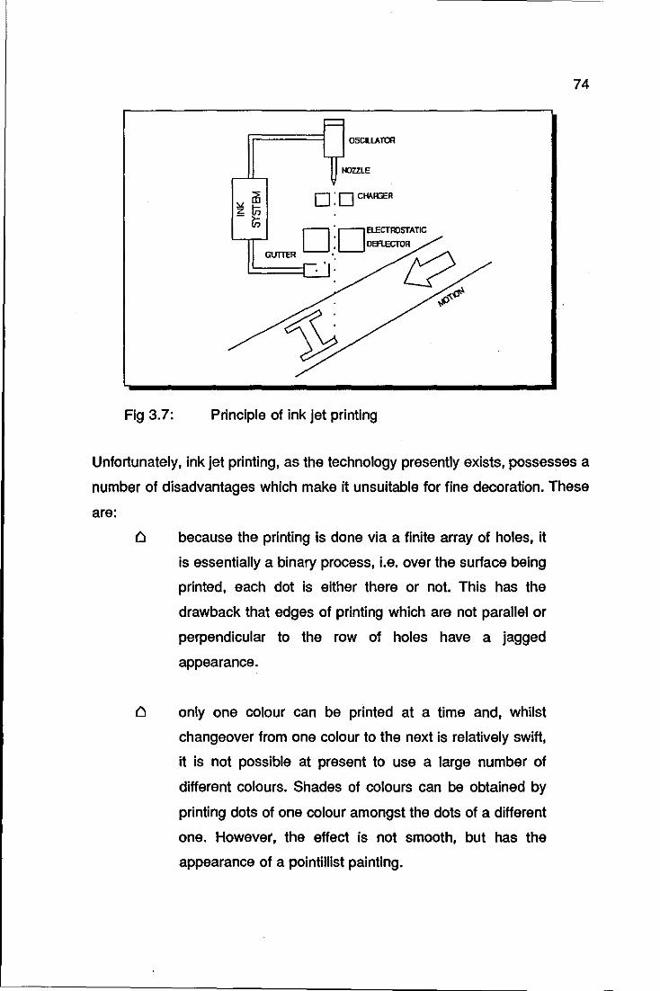
74
OSCR.LA TOO
NOZZLE
'" ill 0 : 0 CHAlaR zln -,.
If) 0 :OEtECTRJSTATIC '--,,......J • DIRECTOR
GUTTER •• ': L:? . ,f)<.(!i'
~ Fig 3.7: Principle of ink jet printing
Unfortunately, ink jet printing, as the technology presently exists, possesses a
number of disadvantages which make it unsuitable for fine decoration. These
are:
Cl because the printing is done via a finite array of holes, it
is essentially a binary process, i.e. over the surface being
printed, each dot Is either there or not. This has the
drawback that edges of printing which are not parallel or
perpendicular to the row of holes have a jagged
appearance.
only one colour can be printed at a time and, whilst
changeover from one colour to the next is relatively swift,
it is not possible at present to use a large number of
different colours. Shades of colours can be obtained by
printing dots of one colour amongst the dots of a different
one. However', the effect is not smooth, but has the
appearance of a pointillist painting.
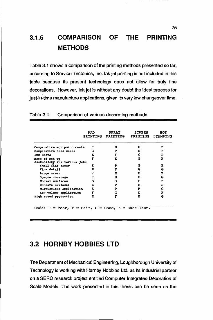
75
3.1.6 COMPARISON
METHODS
OF THE PRINTING
Table 3.1 shows a comparison of the printing methods presented so far,
according to Service Tectonics, Inc. Ink jet printing is not included in this
table because its present technology does not allow for truly fine
decorations. However, ink jet is without any doubt the ideal process for
just-in-time manufacture applications, given its very low changeover time.
Table 3.1: Comparison of various decorating methods.
PAD SPRAY SCREEN HOT PRINTING PAINTING PRINTING STAMPING
Comparative equipment cost. P Comparative tool costs G Ink costa E Ease of sat up F Suitability for various jobs
Small f1at areas E Fine detail E Large areas P Opaque coverage P Convex surfaces E Concave surfaces E Multicolour application E Low volume application F
High speed production E
E P F E
P P E E G P P G F
G E G G
G G E E F P P E E
Code: P - Poor, F = Fair, G = Good, E - Excellent.
3.2 HORNBY HOBBIES L TO
F F P P
E G P G F P G F G
The Department of Mechanical Engineering, Loughborough University of
Technology is working with Hornby Hobbies Ltd. as its industrial partner
on a SERC research project entitled Computer Integrated Decoration of
Scale Models. The work presented in this thesis can be seen as the
76
foundation for that project.
A chronological review of the company is given in this section, the main
problems related to product decoration are stressed and the reasons
why Hornby is now seeking ways of automating their production methods
are presented.
3.2.1 FROM 1952 TO THE PRESENT
1952: In order to market his range of novel clockwork powered cars,
Fred Francis started a company called Minimodels Limited. These
were metal bodied models of sports and racing cars and their
trade mark was SCALEX.
1956: The inventor/proprietor of Minimodels modified his cars to take an
electric motor and devised a rubber based track system with two
parallel grooves in which metal rails carried electric current and
guided the cars by means of a gimbal wheel suspended beneath
them. The new product was called SCALEXTRIC, SCALEX
elecTRIC.
1958: SCALEXTRIC was unveiled to the toy trade at the annual
Harrogate Toy Fair, causing an immediate sensation and orders
flowed in, far in excess of the factory production capability. As an
alternative to making substantial investments in a new factory,
Minimodels was sold to the Tri-ang Group.
1960: Tri-ang launched four new cars fitted with Tri-ang's well tested
electric motors and accurately moulded plastic bodies.
1961: A 24 page catalogue revealed a host of racing accessories,
bridges and bankings based on the real items to be found at
77
Goodwood circuit in Sussex. Such was the demand that a new
factory was built solely for the purpose of manufacturing
Scalextric.
1963: The original rubber track, supplied by a contract rubber supplier
was replaced by a polyethylene track, which started being
moulded at the Tri-ang factory. By this time, there were 18
different cars, two motorcycle combinations and two Go-karts in
the range.
1964: Scalextric was being manufactured in Tri-ang factories in France,
Australia and New Zeland and by an associated company in
Spain. It was sold in the USA in partnership with Lionel, the
famous train makers.
1965: Two gimmicks were introduced, the blow-out puncture
simulator and Twin auto screams, a realistic noise making device
not universally popular.
1970: In an attempt to revive flagging sales first experienced in 1969,
another gimmick was launched: 'You Steer', a special hand
throttle Incorporating a small steering wheel. As this was turned,
it changed the polarity of the current to the car and by an
amazingly ingenious and simple device, made the car swerve
whilst maintaining its forward direction, so that it could, to a
degree, avoid objects in its path. Although the theory was sound
and the cars performed as intended, the problem was thaUhe
driver had little time to carry out the manoeuvre he wanted. 'You
Steer' was not a success and Minimodels Limited was in some
difficulties. The decision was taken to close the factory and
transfer production to an associated company, Rovex (now called
Hornby Hobbies Limited) at Margate. Rovex produced Tri-ang
78
Hornby model trains and were familiar with the type of production
needed for Scalextric.
1972: Rovex introduced a 60 degree banked track section which
connected directly to all the other track sections and enabled a
banked figure of 8 circuit to be constructed with only 14 track
sections, and a simple banked oval circuit with 8 sections. This
move has been universally rejected ever since, as to enable cars
to use the banking, it was necessary to manufacture cars with the
front 'wheels' clear of the track and provide a lot of free
movement in the axle.
1977: The logos were printed directly onto the cars, using the pad
printing technology, to replace the transfers previously supplied
and this made the cars look more attractive, as easily seen in
Figure 3.8, and proved far more durable. Gimmicks were carefully
avoided throughout the 70's.
1980: The instant appeal of the home computer undermined
Scalextric sales in the early 80's. However, this phase quickly
passed and by its 30th birthday in 1987, the variety and quality
of the models had reached a superb level.
Detailing and accuracy of outline are given great attention in Scalextric
models today and the quality of the colours and markings are
outstanding. The latest electric motors provide speeds comparable with
the full size prototypes and working head, tail and brake lights add to the
realism. The Hornby factory at Margate, many times extended from the
original Tri-ang building is equipped with modern machinery; injection
moulding of plastic components is done on fully automatic machines,
decoration and assembly are all carried out in the factory.
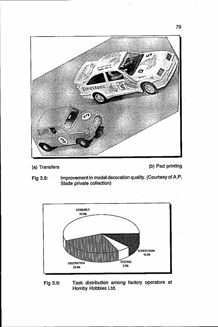
79
(a) Transfers (b) Pad printing
Fig 3.8: Improvement in model decoration quality. (Courtesy of A.P.
Fig 3.9:
Slade private collection)
ASSEMBlY
2Sm.;
Task distribution among factory operators at Hornby Hobbies Ltd.
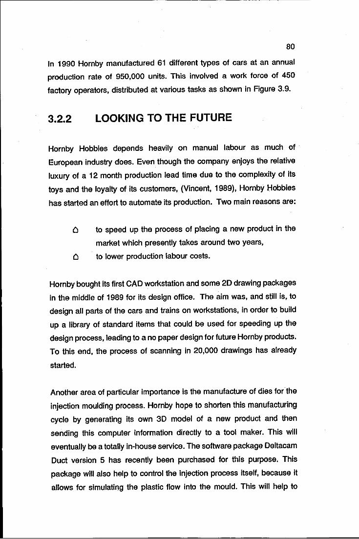
80
In 1990 Hornby manufactured 61 different types of cars at an annual
production rate of 950,000 units. This involved a work force of 450
factory operators, distributed at various tasks as shown in Figure 3.9.
3.2.2 LOOKING TO THE FUTURE
Hornby Hobbies depends heavily on manual labour as much of
European industry does. Even though the company enjoys the relative
lUxury of a 12 month production lead time due to the complexity of its
toys and the loyalty of its customers, (Vincent, 1989), Hornby Hobbies
has started an effort to automate its production. Two main reasons are:
to speed up the process of placing a new product in the
market which presently takes around two years,
to lower production labour costs.
Hornby bought its first CAD workstation and some 20 drawing packages
in the middle of 1989 for its design office. The aim was, and still is, to
design all parts of the cars and trains on workstations, in order to build
up a library of standard items that could be used for speeding up the
design process, leading to a no paper design for future Hornby products.
To this end, the process of scanning In 20,000 drawings has already
started.
Another area of particular importance is the manufacture of dies for the
injection moulding process. Hornby hope to shorten this manufacturing
cycle by generating its own 3D model of a new product and then
sending this computer information directly to a tool maker. This will
eventually be a totally in-house service. The software package Deltacam
Duct version 5 has recently been purchased for this purpose. This
package will also help to control the injection process itself, because it
allows for simulating the plastic flow into the mould. This will help to
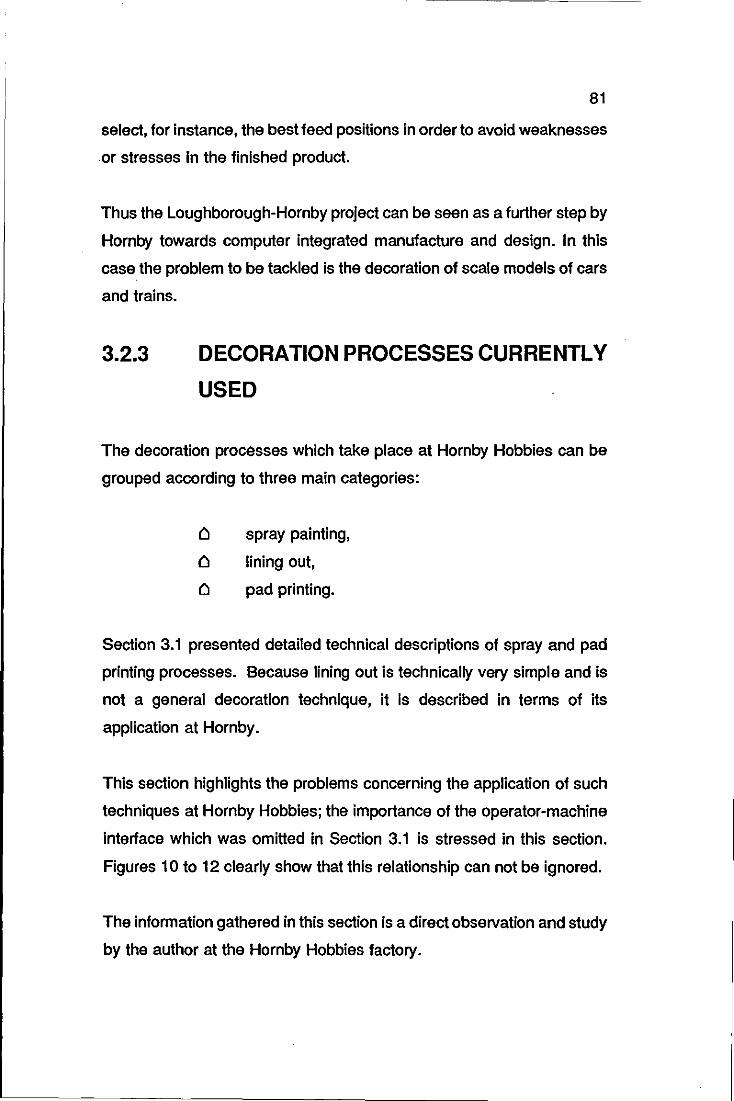
81
select, for instance, the best feed positions in order to avoid weaknesses
or stresses in the finished product.
Thus the Loughborough-Hornby project can be seen as a further step by
Hornby towards computer integrated manufacture and design. In this
case the problem to be tackled is the decoration of scale models of cars
and trains.
3.2.3 DECORATION PROCESSES CURRENTLY
USED
The decoration processes which take place at Hornby Hobbies can be
grouped according to three main categories:
t! spray painting,
t! lining out,
t! pad printing.
Section 3.1 presented detailed technical descriptions of spray and pad
printing processes. Because lining out is technically very simple and is
not a general decoration technique, it is described in terms of its
application at Hornby.
This section highlights the problems concerning the application of such
techniques at Hornby Hobbies; the importance of the operator-machine
interface which was omitted in Section 3.1 is stressed in this section.
Figures 10 to 12 clearly show that this relationship can not be ignored.
The information gathered in this section is a direct observation and study
by the author at the Hornby Hobbies factory.
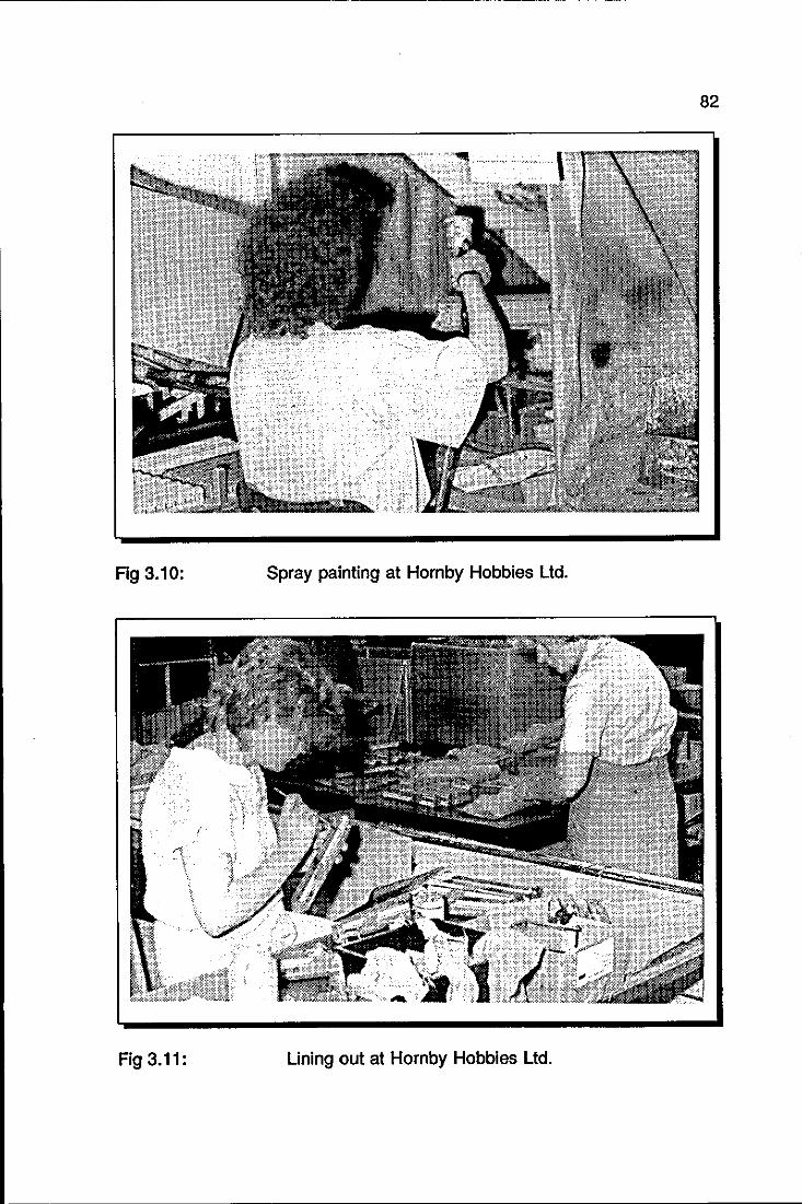
82
Fig 3.10: Spray painting at Hornby Hobbies Ltd.
Fig 3.11: Lining out at Hornby Hobbies Ltd.
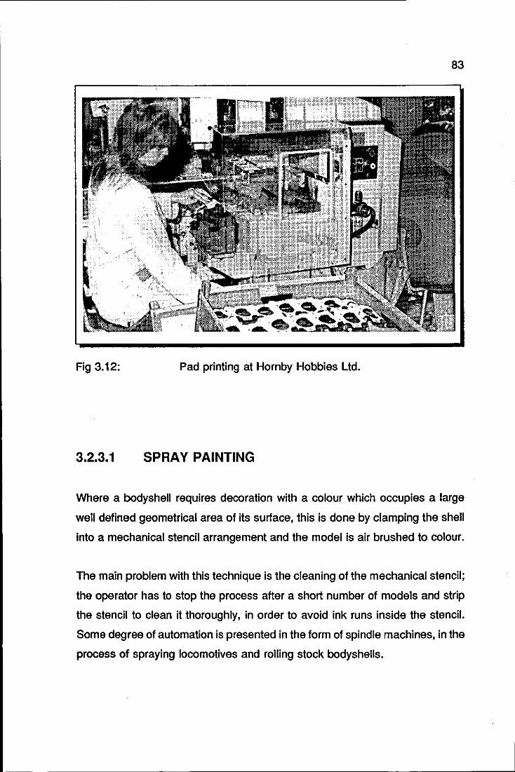
83
Fig 3.12: Pad printing at Hornby Hobbies Ltd.
3.2.3.1 SPRAY PAINTING
Where a bodyshell requires decoration with a colour which occupies a large
well defined geometrical area of its surface, this is done by clamping the shell
into a mechanical stencil arrangement and the model is air brushed to colour.
The main problem with this technique is the cleaning of the mechanical stencil;
the operator has to stop the process after a short number of models and strip
the stencil to clean it thoroughly, in order to avoid ink runs inside the stencil.
Some degree of automation is presented in the form of spindle machines, in the
process of spraying locomotives and rolling stock bodyshells.
84
Spray painting is recognised as the area where most cost savings can be made
as probably 80% of the paint is wasted in spray mist and overspray onto the
mask. It is here that ink jet would have the largest impact, given the present
limitations of ink jet technology.
3.2.3.2 LINING OUT
A particularly expensive operation is that of applying thin lines to the body
shells of locomotives and other rolling stock. This is necessary to pick out hand
rails, roof edges and so on. This can only be done manually (at present) since
the parts to be inked are either recessed, as are the handrails, or are proud,
as in the case with roof edges.
The method presently used is for an operator to ink these lines in manually
using a claw or mapping pen. The open nature of the pen and the fact that very
little paint can in fact be carried in the pen means that it is constantly having
to be cleaned and refilled. Also this operation requires a high degree of
concentration even though the job itself is relatively simple, and consequently
the work throughput is low, around six to ten models an hour. This method has
the following features:
The operator must be trained. This can be lengthy process, up
to 6 months.
He may decide to leave soon afterwards necessitating the training
of another person.
The process is slow and prone to error.

85
3.2.3.3 PAD PRINTING
The detail decorations are added to the bodyshells by this prQcess. In the case
of the cars and trucks, these will be in the form of the logos and colour
schemes for the various advertisements which the model carries, together with
race numbers, etc. In the case of locomotives and rolling stock these will be
various informational panels, company names, etc.
Screen printing and hot stamping are also printing techniques that could have
been used for this particular decoration. Screen printing was ruled out because
many models require wet-on-wet operations which this technique is unable to
provide; hot stamping was ruled out on the basis of cost, significantly higher
than that of pad printing.
In this decoration process, each shell is lifted from a conveyor belt or from a
box and fitled onto a specially shaped matrix which holds it accurately in place
and stops the shell deforming during the printing process. A set of silicone
rubber pads picks up printing ink of the required logo from a printing plate and
deposits it onto the body shell held on the jigging.
Each model body shell must have logos printed on it in different colours and in
different positions. At present the factory based system provides a set of
printing machines each of which can be set to print up to three or four logos in
up to three different colours. The operator is presented with a box full of
partially decorated shells. He takes out one shell4 and fits it onto the jig (model
matrix) at the front of the printing machine and holds it in place. The machine
is then actuated and performs one print cycle. The operator then removes the
body shell and places it on the conveyor. He selects another shell from the box
and continues. Meanwhile a second operator at the end of the conveyor picks
up the shells, wraps them in tissues and boxes them ready for the next
4 sometimes two or three
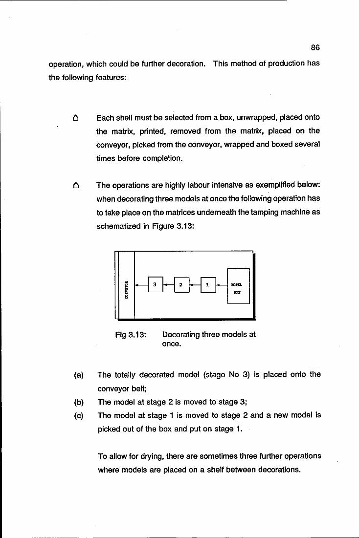
86
operation, which could be further decoration. This method of production has
the following features:
Each shell must be selected from a box, unwrapped, placed onto
the matrix, printed, removed from the matrix, placed on the
conveyor, picked from the conveyor, wrapped and boxed several
times before completion.
The operations are highly labour intensive as exemplified below:
when decorating three models at once the following operation has
to take place on the matrices underneath the tamping machine as
schematized in Figure 3.13:
Fig 3.13:
lIOlIn
BOX
Decorating three models at once.
(a) The totally decorated model (stage No 3) is placed onto the
conveyor belt;
(b) The model at stage 2 is moved to stage 3;
(c) The model at stage 1 is moved to stage 2 and a new model is
picked out of the box and put on stage 1.
To allow for drying, there are sometimes three further operations
where models are placed on a shelf between decorations.
87
When a tamping machine is having its printing plate changed to
print a different logo it must also have its matrix changed to
present a different side of the shell to the rubber pad.
It was mentioned in Section 3.1.1.3 that the pad printing process offers a
number of possibilities of automation by the use of linear conveyor belts, shuttle
arrangements, carousels and ultimately, high production rates can be obtained
on its modified rotary version.
Unfortunately, off-the-shelf automation is not present on the majority of the 44
pad machines presently operating at Hornby. There are four main reasons to
explain this:
a bodyshell has to be placed in different positions and
orientations in order to receive decoration on all its faces. An
average number of positions is 7: bonnet, roof, boot, left hand
side, right hand side, front and rear. It is very easy to visualise
the mechanical problems of designing a mechanism that would
convey the body shells from a machine which prints their
bonnets to a machine which prints their sides.
the accuracy of some wet-on-wet printing operations practically
rules out conveyor systems as ways of positioning the body shells
under the printing heads.
the operator not only places the bodyshells onto the matrices,
but also holds them in place. This is necessary to avoid the
bodyshells being dragged up by the silicone pad after the
application of the logo, given their light weight. Any form of
automation will have to mimic this operation.
3.2.3.3.1
88
the automation of the process has to allow the setting up
of the printing machine to be precisely executed, mainly
when wet-on-wet printings are required. The setting up of
the machine is presently manually executed; the author
believes this can not be executed otherwise. The reasons
are detailed in the item below.
SETTING UP OF PAD PRINTING MACHINES
The setting up of the pad printing machines is a lengthy operation, up
to two hours, executed at Hornby by specially trained technicians. This
time can easily exceed three hours as those technicians are also in
charge of the on-line maintenance of the operating printing machines.
The machine setting up consists of: (a)fastening of the printing plate and
ink tray, (b)obtaining the right ink viscosity, (c)levelling the spatula,
(d)adjusting the proper blade pressure and scraping limit, (e)positioning
of the pads, (f) positioning the model matrix under the pads and
(g)selecting movement speeds.
(a) printing plate and ink tray attachment this is the easiest
adjustment of the process; the printing plate is slid into the
ink tray and fastened. The ink tray is slid into the location
plate and fastened. If more then one colour is required,
plastic separators are glued onto the ink tray.
(b) ink viscosity. the right ink viscosity is obtained by adding
thinners to the ink. No viscosity meter is used; the right
viscosity is based upon the technician's experience.
89
(c) spatula mounting: the level of the spatula is adjusted
according to the level of ink, so that the whole image in
the printing plate can be covered by the ink. This is
achieved by a trial-and-error operation, where the
technician adjusts a single screw and inspects the result
on the printing plate.
(d) doctor blade adjustments: after being fixed to the blade
holder, the blade pressure has to be adjusted so that only
the ink in the etched parts of the cliche remains. This is
achieved by a combination of a pressure regulator to
control the pressure on the blade holder (course
adjustment) and screw adjustment on the blade itself (fine
adjustment). Again, this is a trial-and-error operation,
visually checked by the technician. The optimal pressure
is a trade-off between the guarantee that ink will only be
left in the etched areas of the cliche and that excessive
blade pressure will not be used, in order to avoid
shortening blade and cliche lives. The length of the blade
scraping action is adjustable by a limit valve/slide sensor,
depending upon the size of the printing plate.
(e) pad positioning: the pad is attached to the pad holder unit
which has two degrees of freedom in a plane parallel to
the printing plate. The centre of the pad can therefore, be
positioned at the image centre. The pad pickup stroke
(pressure) is controlled by a limit switch. This pressure is
critical for obtaining the correct pickup of the ink from the
cliche.
90
(f) model matrix positioning. the height of the work table
where the model matrix is attached is adjusted to align the
surface to be printed with the printing plate. The
adjustments in the x-y plane are determined by the
position of the pad in the pad holder. The pad stroke at the
printing position is selected by a trial and error approach
with visual inspection.
(g) movement speeds: the pad machine throughput is
determined by four air flow regulators. which control the
speed of the following movements: pad up and down at
inking position, pad carriage forward and backward. The
operational cycle time is however determined by the
operational efficiency of the operator. This will of course
depend upon how many models are being decorated at
any time.
With the exception of items (b) and (g), all the other setting up steps
require visual feed back for the adjustment of a particular parameter.
Any attempt to automate the setting up procedure would require the
positioning of cameras in inaccessible places in some instances.
Moreover, mobile cameras would be needed in some situations, in order
to allow for the movement of the pad and pad carriage.
Also, in the minimum case, single logo-single pad combination, 48
actuators would need to be added to the machine in order to adjust the
various knobs and screws used in its setting up. For each extra logo-pad
combination, there will be six more adjustments to be considered. Thus,
the author finds the scenario unrealistic of fully automating the setting up
of the present machines. This will affect the automation of the on-line
operation of the machines, as this has to allow room, for a technician to
set them up.
91
3.3 LOUGHBOROUGH UNIVERSITY & HORN BY
HOBBIES L TO. COOPERATIVE EFFORT
In the middle of 1988 the Department of Mechanical Engineering at
Loughborough University of Technology and the Manufacturing Department of
Hornby Hobbies Limited held the first meetings to address future cooperation
in automation of production at Hornby. The items addressed were assembly
and decoration of scale models. Decoration, however was the item which
required speedy attention, mainly because:
Cl it presents the highest staff turnover, almost 100% in 1989,
Cl it poses some safety problems like fumes and broken fingers in
the spray and pad printing processes, respectively.
its percentage cost to the total cost of the model is significant,
amounting to 15% in some models.
the staff training is lengthy, usually two weeks for pad
machines and six months for lining out operations.
approximately half the manufacturing time is spent in decoration.
Initial suggestions of production improvement were given in the three decoration
processes, namely spraying, pad printing and lining out.
In the case of spraying, it was an automatic stencil arrangement that would
automatically close, open and clean itself.
With regards to the lining out process, a novel end effector to fit directly onto
the end of a PUMA robot together with its own cleaning unit was designed in
order to speed up the throughput of this process. This system makes for a
very tidy, compact unit which avoids the need for operators to keep stopping
work to clean pens or mix up a fresh batch of paint. In initial trials they have
significantly reduced the painting times down to less than 100 seconds for
92
some models. The concept and initial programming took less than two weeks
to accomplish compared to the six months training necessary for each operative
at present.
It appeared that devices like those mentioned above could greatly improve the
throughput of both the spraying and lining out processes. Obviously the
framework of an automatic, alternative process for the spraying and lining out
processes had not been defined. Such a framework would encompass the way
that the bodyshell would be automatically placed onto a matrix, the necessary
robot tooling for the process, the quality control strategy, and so forth.
It was decided that these steps would be undertaken for the pad printing
process which, when compared to the other decoration processes, seemed to
be the one which would pose a real challenge for automation. It is believed that
such framework has now been achieved in an original manner, the mechatronic
way. A fully and detailed description of this framework now follows.
93
CONCLUSION
'Decoration process' can be a misleading expression as one can think of it as
a process that does not require tight tolerances, it is very Simple and has little
importance in the final product. Section 3.1 proved otherwise. In an ever
increasing competitive market, decoration can be the decisive factor to boost
the sales of a product. This was certainly the case at Hornby Hobbies Ltd. in
1977, when the model decoration technique was changed from transfers to pad
printing.
Automation is usually applied to decoration processes in order to increase their
throughput; this is achieved by adding standard equipment such as conveyors,
shuttles and so on to the original machinery. The degree of automation,
however, depends upon the task to be executed. In the case of decoration of
scale model of cars, for instance, there was no immediate solution to be found
in the standard methods of automation. The reasons are given in Section
3.2.3.3.
This has been highlighted by the cooperative effort between the Department of
Mechanical Engineering, Loughborough University of Technology and Hornby
Hobbies Ltd. and has motivated the realisation of this thesis.
------_._.
94
CHAPTER 4
MECHATRONIC DECORATION CELL:
DESIGN
MECHATRONIC DECORATION CELL
DESIGN
RECOGNITION OF THE NEED
DESIGN REQUIREMENTS
HIERARCHY OF FUNCTIONAL
REQUIREMENTS
PRINCIPLE FOR GRASPING THE
BODYSHELLS
EQUIPMENT AVAILABLE FOR
COMMISSIONING OF THE DECORATION CELL
96
SUMMARY
The design of the decoration cell follows the steps of the Mechatronics design
methodology proposed in Chapter 2.
The recognition of the need of the decoration cell is briefly discussed in Section
4.1. The design requirements of it are presented in Section 4.2. For the sake
of design simplicity, a hierarchical structure of the functional requirements is
also proposed. As a consequence, the design of the decoration cell is split into
five separate, but at the same time integrated, operational stations. This
integration covers the three areas of Mechatronics, hence, it is called
Mechatronics Integration.
Careful handling of the bodyshells was a functional requirement readily
identified at the Design Requirements phase of the Mechatronics Design
Methodology. The various means of meeting this requirement are discussed
in Section 4.2.2.
In order to gauge the final functional requirements of some components of the
cell in a quick and comprehensive manner, equipment available within the
Department was used. This is described in the final section of the chapter.
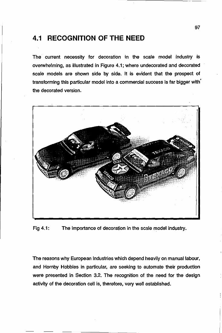
97
4.1 RECOGNITION OF THE NEED
The current necessity for decoration in the scale model industry is
overwhelming, as illustrated in Figure 4.1; where undecorated and decorated
scale models are shown side by side. It is evident that the prospect of
transforming this particular model into a commercial success is far bigger with
the decorated version.
Fig 4.1: The importance of decoration in the scale model industry.
The reasons why European industries which depend heavily on manual labour,
and Hornby Hobbies in particular, are seeking to automate their production
were presented in Section 3.2. The recognition of the need for the design
activity of the decoration cell is, therefore, very well established.
•
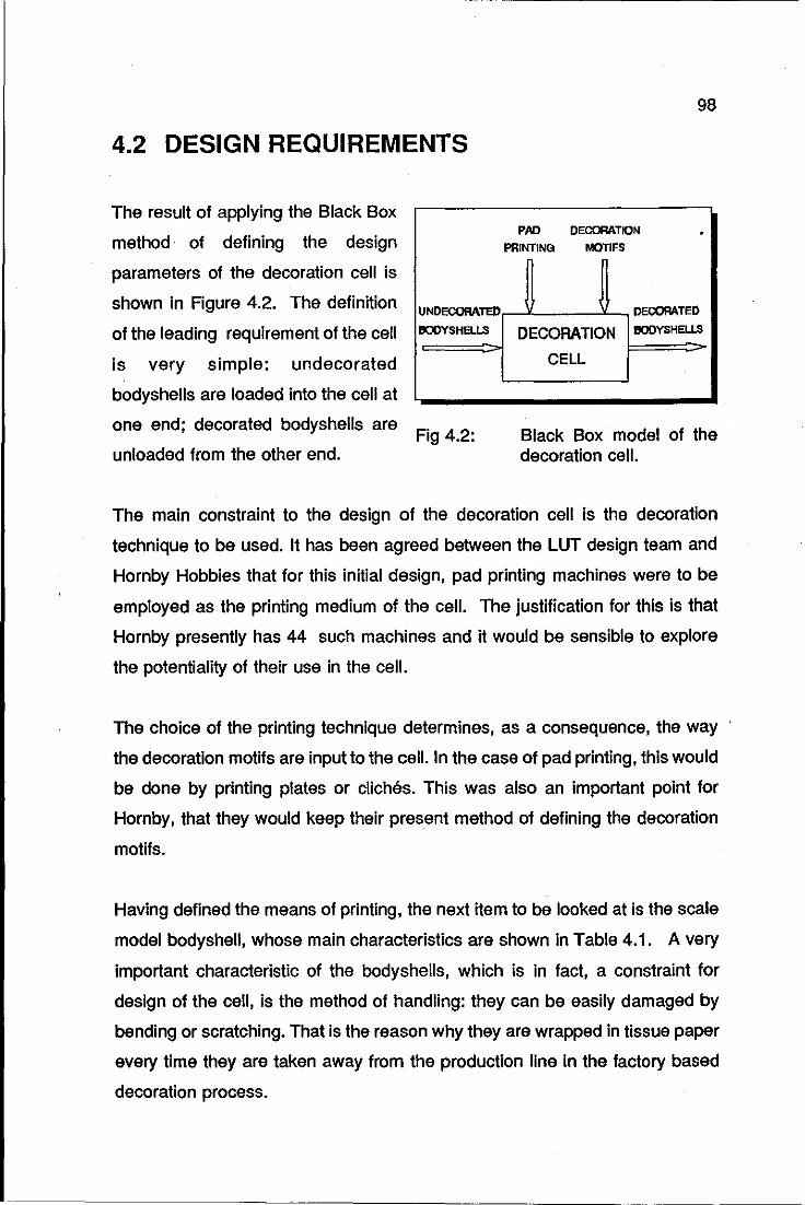
4.2 DESIGN REQUIREMENTS
The result of applying the Black Box
method· of defining the design
parameters of the decoration cell is
shown in Figure 4.2. The definition
of the leading requirement of the cell
is very simple: undecorated
bodyshells are loaded into the cell at
one end; decorated bodyshells are
unloaded from the other end.
UNDECORATED
IIODYSHELLS
Fig 4.2:
98
PAD DECORATION PRINTING MOTIFS
DECORATED
DECORATION IIODYSHELLS
CELL
Black Box model of the decoration cell.
The main constraint to the design of the decoration cell is the decoration
technique to be used. It has been agreed between the LUT design team and
Hornby Hobbies that for this initial design, pad printing machines were to be
employed as the printing medium of the cell. The justification for this is that
Hornby presently has 44 such machines and it would be sensible to explore
the potentiality of their use in the cell.
The choice of the printing technique determines, as a consequence, the way
the decoration motifs are input to the cell. In the case of pad printing, this would
be done by printing plates or cliches. This was also an important point for
Hornby, that they would keep their present method of defining the decoration
motifs.
Having defined the means of printing, the next item to be looked at is the scale
model bodyshell, whose main characteristics are shown in Table 4.1. A very
important characteristic of the bodyshells, which is in fact, a constraint for
design of the cell, is the method of handling: they can be easily damaged by
bending or scratching. That is the reason why they are wrapped in tissue paper
every time they are taken away from the production line in the factory based
decoration process.
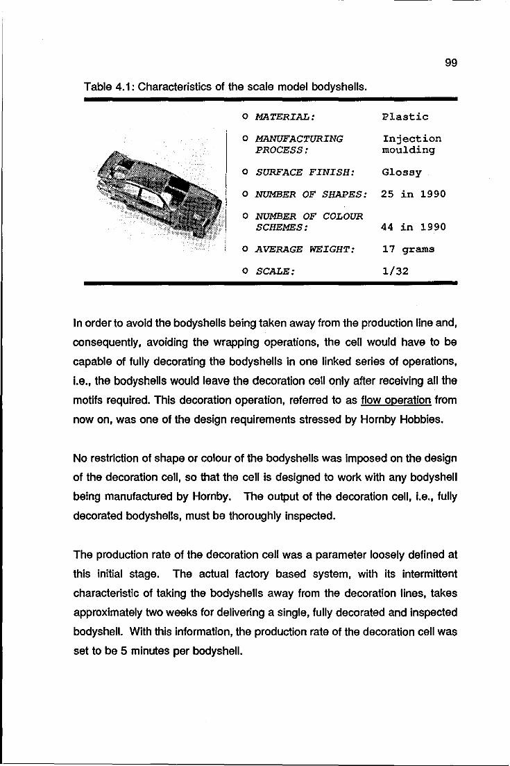
99
Table 4.1: Characteristics of the scale model bodyshells.
o MATERIAL: Plastic
o MANUFACTURING Injection PROCESS: moulding
o SURFACE FINISH: Glossy
o NUMBER OF SHAPES: 25 in 1990
o NUMBER OF COLOUR SCHEMES: 44 in 1990
o AVERAGE WEIGHT: 17 grams
o SCALE: 1/32
In order to avoid the bodyshells being taken away from the production line and,
consequently, avoiding the wrapping operations, the cell would have to be
capable of fully decorating the bodyshells in one linked series of operations,
i.e., the bodyshells would leave the decoration cell only after receiving all the
motifs required. This decoration operation, referred to as flow operation from
now on, was one of the design requirements stressed by Hornby Hobbies.
No restriction of shape or colour of the bodyshells was imposed on the design
of the decoration cell, so that the cell is designed to work with any bodyshell
being manufactured by Hornby. The output of the decoration cell, i.e., fully
decorated bodyshells, must be thoroughly inspected.
The production rate of the decoration cell was a parameter loosely defined at
this initial stage. The actual factory based system, with its intermittent
characteristic of taking the bodyshells away from the decoration lines, takes
approximately two weeks for delivering a single, fully decorated and inspected
bodyshell. With this information, the production rate of the decoration cell was
set to be 5 minutes per bodyshell.
100
The summary of the design requirements of the decoration cell is summarised
in the following statement:
4.2.1
Design a cell which is capable of decorating and inspecting any
bodyshell manufactured by Homby Hobbies Ltd., using the pad
printing technique in a flow operation at a production rate of 60
bodyshells per hour.
HIERARCHY
REQUIREMENTS
OF FUNCTIONAL
The leading functional requirement of the decoration cell is the placement of
logos and decorations onto bodyshells. Taking an undecorated bodyshell
through the various stages needed for the completion of its decoration, it is
possible to identify the second level of the functional requirements of the cell.
After leaving the injection moulding machines, the bodyshells need to be:
o loaded into the cell,
o identified,
o decorated,
o inspected and
o palletised for further operations.
The recognition of these requirements has led to the partition of the design of
the decoration cell into five stations, each of them performing the functional
requirements mentioned above.
The Black Box method can now be applied to each individual station; the
outcome of this exercise is shown in Figure 4.3. In this figure, the black boxes
are shown in an integrated way, that is, the input of the second box is the
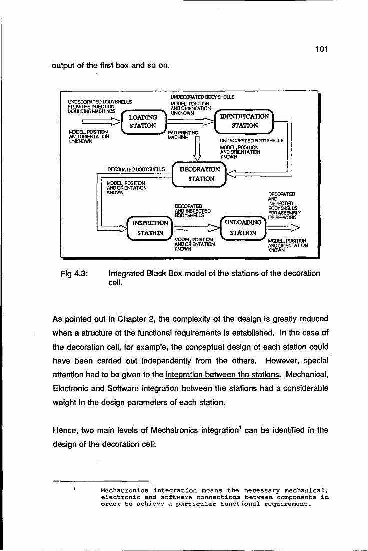
output of the first box and so on.
UNDECORATED OODYSHElLS FRCMTHE INJECTDN MOUlD It-Ki MACHINES
LOADING STATION
UNDECORATED OOOYSHElLS MJDEL. PDSITON ANDDRIENfATON UNKNOWN IDHNTIFICATION
STATION I-
PDSITON RIENfATON
MJDEl ANOO UNKNOW
PAOPRINTtG
N MACH NE
UNDECORATED OODYSHELLS I.()DEL PDSITON AND ORIENTATON KNJWN
DECORATED BODYSHELLS DECORATION
MDDEl. POSITON STATION
I<
AND ORIENTATON KNJWN DECOOATED
AND DEOORATED INSPECTED
OOOYSHELL5 AND INSPECTED FOR ASSEMBLY OODYSHELLS DRRE-WORK INSPECTION UNWADING
>I > STATION
MODel PDSITON ANOORIENfATON KNOWN
STATION MODEl, POSIT ON ANOORIENTAHlN KNOWN
101
Fig 4.3: Integrated Black Box model of the stations of the decoration cell.
As pointed out in Chapter 2, the complexity of the design is greatly reduced
when a structure of the functional requirements is established. In the case of
the decoration cell, for example, the conceptual design of each station could
have been carried out independently from the others. However, special
attention had to be given to the integration between the stations. Mechanical,
Electronic and Software integration between the stations had a considerable
weight in the design parameters of each station.
Hence, two main levels of Mechatronics integration1 can be identified in the
design of the decoration cell:
Mechatronics integration means the necessary mechanical, electronic and software connections between components in order to achieve a particular functional requirement.
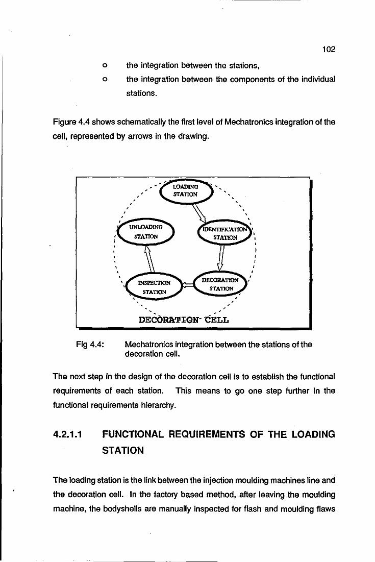
102
o the integration between the stations,
o the integration between the components of the individual
stations.
Figure 4.4 shows schematically the first level of Mechatronics integration of the
cell, represented by arrows in the drawing.
, , ,
, ,
Fig 4.4: Mechatronics integration between the stations of the decoration cell.
The next step in the design of the decoration cell is to establish the functional
requirements of each station. This means to go one step further in the
functional requirements hierarchy.
4.2.1.1 FUNCTIONAL REQUIREMENTS OF THE LOADING
STATION
The loading station is the link between the injection moulding machines line and
the decoration cell. In the factory based method, after leaving the moulding
machine, the bodyshells are manually inspected for flash and moulding flaws

103
and then conveyed to a point where they are manually wrapped and packed in
cardboard boxes in an ordered manner. These boxes are then distributed
among the various printing machines.
It was not within the scope of the present work to investigate in depth the
various ways of bringing the bodyshells to the loading station. However, a
sensible way of doing so would be to extend the existing net of conveyor belts
from the moulding machines, straight to the loading station. It was assumed
that the same initial inspection of the bodyshells would be maintained. An
assumption was made in that the bodyshells would be upright before arriving
- at the loading station.
The leading functional requirement for the loading station was flexibility,
expressed at the top level of the functional hierarchy of the decoration cell as
• ... capable of decorating any bodyshell .. .". There were initially two possible
approaches for achieving this requirement:
1) A single conveyor belt feeding a single loading station with different
bodyshells,
2) A number of conveyors, each carrying the same type of bodyshell,
feeding the corresponding number of loading stations.
The first approach would require some form of identification of the bodyshells
as they were transferred into the cell. Moreover, it would require automatic
adjustment mechanisms for the station, as the bodyshells vary in shape and
size. This could be a viable solution if the pad printing machine were capable
of rapid changeover from one set-up to another. (See Section 3.3.3.1 for the
set-up of the pad printing machine).
The obvious problem of the second approach is the number of loading stations
needed, even though no identification or adjustment mechanisms would be
required.
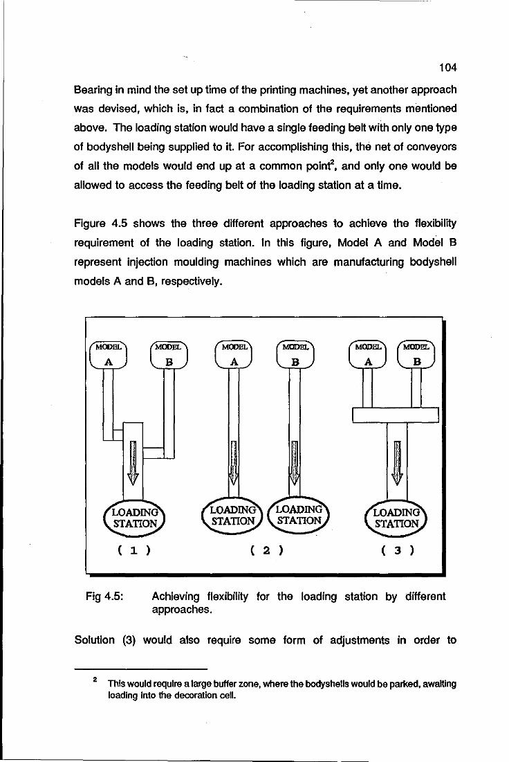
104
Bearing in mind the set up time of the printing machines, yet another approach
was devised, which is, in fact a combination of the requirements mentioned
above. The loading station would have a single feeding belt with only one type
of bodyshell being supplied to it. For accomplishing this, the net of conveyors
of all the models would end up at a common poinr, and only one would be
allowed to access the feeding belt of the loading station at a time.
Figure 4.5 shows the three different approaches to achieve the flexibility
requirement of the loading station. In this figure, Model A and Model B
represent injection moulding machines which are manufacturing bodyshell
models A and B, respectively.
( 1 )
Fig 4.5:
( 2 ) ( 3 )
Achieving flexibility for the loading station by different approaches.
Solution (3) would also require some form of adjustments in order to
2 This would require a large buffer zone, where the bodyshells would be parked, awaiting loading Into the decoration cell.
105
accommodate all the models. However, the necessary adjustments would be
carried out at the same time that the printing machines were being changed for
the new models. The other functional requirements identified for the loading
station were:
o Mechatronics integration with the identification station,
o Careful handling of the bodyshells,
o Ability to detect and recover from deviation events.3
These last two requirements are actually requirements for the all stations, and
consequently, they will not be mentioned once again in the functional
requirements of the other stations.
4.2.1.2 FUNCTIONAL REQUIREMENTS OF THE
IDENTIFICATION STATION
Before starting to describe the functional requirements of the identification
station, it is necessary to justify its existence in the first place. Suppose that
the loading station placed the bodyshells onto positioning jigs that would keep
their position accurately; the decoration cell would always know where to pick
up the bodyshells to carry out their decoration. In this scenario, the
identification station would not be needed at all.
There are two setbacks in this strategy: (a)the total cost of the jigs would be
considerable, given the number of different bodyshells and (b)the flexibility of
the cell would have been maintained the hard way, as solution (2), Figure 4.5,
would have to be chosen for the loading station.
3 Deviation events are situations and circumstances that lead to undesirable operation of the cell. They are the opposite of goal events. This subject is fully discussed in Section 8.2.4
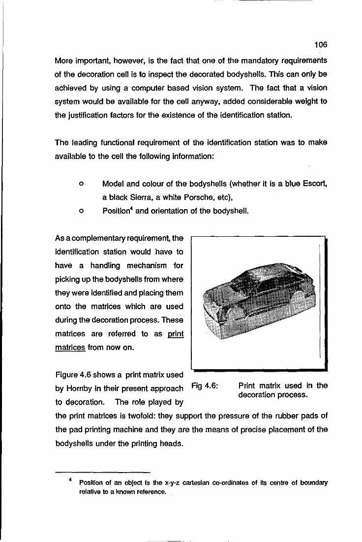
106
More important. however. is the fact that one of the mandatory requirements
of the decoration cell is to inspect the decorated bodyshells. This can only be
achieved by using a computer based vision system. The fact that a vision
system would be available for the cell anyway. added considerable weight to
the justification factors for the existence of the identification station.
The leading functional requirement of the identification station was to make
available to the cell the following information:
o Model and colour of the bodyshells (whether it is a blue Escort.
a black Sierra. a white Porsche. etc).
o Position4 and orientation of the bodyshell.
As a complementary requirement. the
identification station would have to
have a handling mechanism for
picking up the bodyshells from where
they were identified and placing them
onto the matrices which are used
during the decoration process. These
matrices are referred to as print
matrices from now on.
Figure 4.6 shows a print matrix used
by Hornby in their present approach Fig 4.6:
to decoration. The role played by
Print matrix used in the decoration process.
the print matrices is twofold: they support the pressure of the rubber pads of
the pad printing machine and they are the means of precise placement of the
bodyshells under the printing heads.
4 Position of an object Is the x-y-z cartesian co-ordinates of Its centre of boundary relative to a known reference.

107
The other requirements for the identification station are:
o Mechatronics integration with the loading station,
o Mechatronics integration with the decoration station: the
mechanism that picks up the bodyshells at the identification
station interacts with the pad printing machine as well.
o For Mechatronics integration with the inspection station, it would
be desirable to have a common computer based vision system
shared by the identification and inspection stations.
4.2.1.3 FUNCTIONAL REQUIREMENTS OF THE
DECORATION STATION
As pointed out before, the main constraint to the decoration cell was the use
of pad printing technology. This became the leading requirement of the printing
station. Based upon the study of the setting up of the printing machines, it
was decided that this operation would continue to be executed in a manual
fashion. Therefore, any interaction between the handling mechanism and the
pad printing machine would have to allow for the operator to set up the
machine before the cell operational cycle could start. Three other important
requirements are:
a)
b)
c)
4.2.1.3.1
avoiding excessive handling of the bodyshells,
executing the decoration in a flow operation,
keeping the high quality of decoration.
HANDLING OF THE BODVSHELLS
At the factory, the bodyshells are placed onto print matrices that stay stationary
under the pad printing heads. Consequently, the operator has to execute a
Juggling like operation for moving the bodyshells from one matrix to the next,
resulting in excessive manual handling of the shells. This had to be avoided
108
In the design of the decoration cell. The alternative concept was to place a
bodyshell onto a print matrix and to keep it there until the decoration and
Inspection cycles were completed. This concept is referred to as shell-matrix
unity from now on. Obviously this would require some form of mechanism for
transferring the bodyshells from the identification station to the printing station
and lastly, to the inspection station.
4.2.1.3.2 DECORATION IN A FLOW OPERATION
The shell-matrix unity approach was also suitable .for decoration in a flow
operation, as the mechanism for transferring the shells from the identification
station to the printing station should also be able to transfer the bodyshells
between the pad-printing machines needed5 for completion of the decoration.
The throughput of the decoration station was not a parameter to be considered
at this stage, for the reasons pointed out earlier. The criterion of flow operation
overwhelmed it.
4.2.1.3.3 HIGH QUALITY OF DECORATION
The high quality of decoration obtained by the present factory based method
is universally accepted. Keeping the pad printing technique as a means for
applying decoration was, without any doubt, a step towards high quality
assurance. However it solved only part of the problem. Another important
aspect that influences decoration quality is the accurate placement of the
bodyshells under the printing heads, which determines the position of the logo
on the bodyshell.
5 An average number of printing machines needed for completion of a decoration task Is seven. Homby Hobbies did not provide this number for obvious reasons; the machine supplied, however, was sufficient to demonstrate the original Mechatronics approach to scale model decoration. The operation of a complete decoralion with all necessary printing machines was simulated using a robotic simulation package.
109
With regards to logo placement, there are two different requirements:
i) the positioning of a logo within an area of the bodyshell,
ii) the positioning of the layers of motifs for making up a logo.
The accuracy required for (i) is fairly loose, around ± 2 millimetres, whereas for .
(ii), it is very tight, ± 5 I!-millimetres.
This last accuracy figure certainly puts a enormous burden on the design of the
handling mechanism for the decoration station. At this stage, some sort of
guiding system for the handling mechanism was found to be necessary In order
to meet that mechanical accuracy requirement.
The number of degrees of freedom of such a handling mechanism started to
become clear by looking at another requirement of the decoration station, that
of allowing the printing head of the pad machine to access the five main logo
areas6 of the bodyshells. Only a six-degree-of-freedom mechanism would be
able to position a bodyshell in the printing machine at the positions shown in
Figure 4.7.
A technical requirement of the pad printing technique Is that the contact
between the silicone pads and the substrate takes place at an angle close to
90 degrees. This is to avoid the smudging of the logo. For meeting such a
requirement, it is necessary in some instances, to position the bodyshells under
the printing head at an angle that compensates for the curvature of the area to
be printed. This is almost always the case of bonnet decoration, as shown In
Figure 4.7. This requirement alone practically rules out handling mechanisms
with less than 6 degrees of freedom.
6 Roof, bonnet, rear, left and right hand sides.
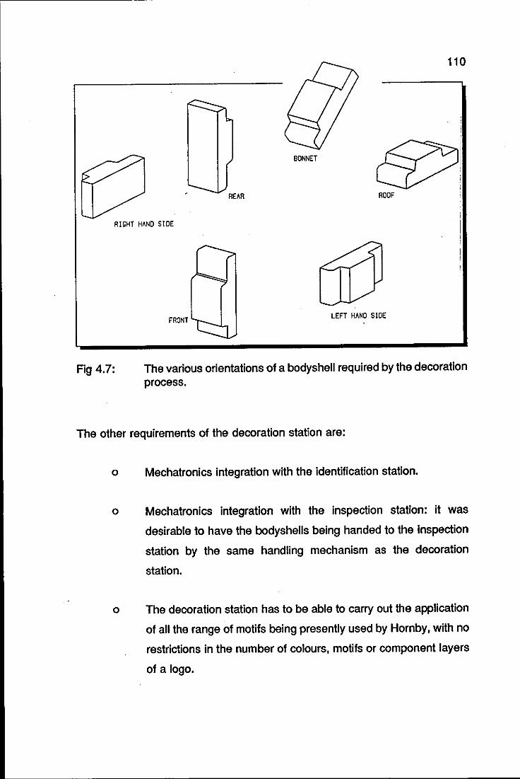
Fig 4.7:
110
BONNET
ROOF
RIGHT HAND SIDE
FRONT LEFT HAND SIDE
The various orientations of a bodyshell required by the decoration process.
The other requirements of the decoration station are:
o Mechatronics integration with the identification station.
o Mechatronics integration with the inspection station: it was
desirable to have the bodyshells being handed to the inspection
station by the same handling mechanism as the decoration
station.
o The decoration station has to be able to carry out the application
of all the range of motifs being presently used by Hornby, with no
restrictions in the number of colours, motifs or component layers
of a logo.
4.2.1.4
111
FUNCTIONAL REQUIREMENTS OF THE INSPECTION
STATION
The logos of the decorated bodyshells need to be inspected for:
o position,
o size,
o completeness and
o shades of colour.
The functional requirements of this station practically defined its conceptual
design: a computer based colour vision system and a positioning mechanism.
This conceptual design justified the existence of the identification station, as
mentioned before.
4.2.1.4.1 COMPUTER BASED VISION SYSTEM
All the items selected for inspection can easily be checked by any commercial
vision system. The main problem Is the integration of such vision systems with
the rest of the cell. To purchase a commercial vision system that would satisfy
the requirements above (most commercial vision systems would) and plug it
into the cell would not be in accordance with the Mechatronics principles of
integration. This approach would perhaps suit CIM or FMS applications, where
there are a number of off-the-shelf options available for making up a complete
system.
To start building a vision system from scratch was not a viable option either.
The ideal vision system for the decoration cell would be a fairly open one, with
the basic operations available, and which would allow access, at a certain level,
to its source code for customising it for the application at hand.
112
4.2.1.4.2 MECHANICAL HANDLING DEVICE
The requirement of mechanical positioning of the bodyshells at the inspection
station was also a very important one. One can identify the operation of
inspection with the mathematical operator subtraction, i.e., the result of the
inspection procedure is arrived at through a comparison, or subtraction,
between the actual image and a reference. For achieving this successfully, the
first requirement to be met is to position accurately the bodyshell always at the
same place. If the system fails to meet this requirement the result of the
inspection is meaningless. The idea of guiding devices attached to the handling
mechanism, as aids to bodyshells placement, again seemed to be adequate.
The logos to be inspected are distributed between the five main areas of the
bodyshells. If only one camera is to be used, then, the handling mechanism
has to move the bodyshell to five different positions and orientations. If more
cameras are used for inspection, fewer positioning operations would be
required from the handling mechanism, with consequential improvement in
mechanical simplicity and reliability. The cost of the extra cameras, obviously,
has to be considered in this option. A further requirement of this station would
be its mechatronics integration with the decoration and unloading station.
4.2.1.5 FUNCTIONAL REQUIREMENTS OF THE UNLOADING
STATION
After being inspected, the decorated bodyshells would be classified as passed
or failed. The unloading station would be required to place the rejected
bodyshells in reject bins for possible rework and palletise the accepted ones for
further operations.
The orientation and position of the bodyshells are known throughout the whole
decoration phases, after being acquired at the identification station. It would
not make sense to lose these attributes at the very last operation of the cell.
113
Therefore, it was found sensible to unload the bodyshells in a way that would
keep their position and orientation known.
It has been said that one way of achieving a low level of handling of the
bodyshells would be to devise a method of keeping them on the print matrices
throughout the decoration process. A handling mechanism would then
manipulate those matrices complete with bodyshells between the decoration
and inspection stations. The first operation necessary for palletising the
bodyshells, would be to take them off the print matrices. That would require a
separate mechanism for the unloading station, but clearly a less complex one
than that used in the decoration and inspection station. A further requirement
is the mechatronics integration with the inspection station. Figure 4.8
summarises the functional requirements of the component stations of the
decoration cell.
Two common requirements of all the stations of the decoration cell were
previously identified, namely the careful handling of the bodyshells and the
ability to detect and recover from deviation events. Whereas the latter has its
solution focused at the individual stations, the former can have a common
solution applicable to all stations. In other words, the handling mechanisms for
the individual stations are different, but their end effectors could use the same
principle for grasping the bodyshells. This solution is discussed below.
4.2.2 CHOICE OF THE PRINCIPLE FOR GRASPING
THE BODYSHELLS SAFELY
The grasping principles commonly used for end effectors are:
o mechanical,
o magnetic,
o vacuum,
o adhesive.
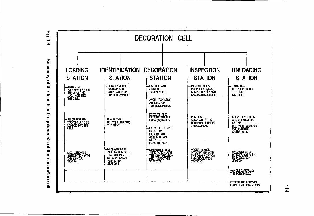
:n (Q DECORATION CELL .",.
CD
I en c: 3 3 LOADING IDENTIFICATION DECORATION INSPECTION UNLOADING ~ STATION STATION STATION STATION STATION S!. - r-!RAN:'fER HDIl'IT FY t.a:lEL. r- LSE THE PAD HNSPECT l.OOO5 - TAKE THE ::r POSlTKlN AND PRINTIr-G FOR POSITKlN!; ~ 1!JD1'aID.lS Off CD I!JDYSHELlS Fl10M
THEMlULOIr-G DRENTATON OF TEOH~LCX;Y ODMPLETENE S D THEPRNT .... MAOHINES INTO THE I!JDYSHELLS. SHADES OFCOLOUlS. MATRCfS • c:
:J THEOELL. I- AVOID EXCESSIVE g, ANDLIr-G OF 0 THE OOOYSHElLS. :J !!!.
r- EXECUTE THE ... ,-PCmIl'l CD I-ALLOW FOR ANY ~SETHE . DECORATKlN IN A r- KEEP THE POSlTKlN
.c FLOIV OPERATON ACCURATelY THE AND ORIIl'IT A TON c: OODYSHELl TO BE 8ODYSHELl5 ONTO I!JDYSHElLS UNDER DFTHE "'. lOADED INTO THE THE PRINT THE CM.£RAS. I!JD1'SHEUS KNOWN CD CELL. I- EXECUTE THE FUU FOR FLIlTHER 3 RAtG: Cl' OPERATKlNS. CD OECORATON :J AVAUBLE AND - KEEP THE If) PRESENT HGH 0 ....
H.4ECHATIIJNICS - ~§CHATRONICS r- t.£OHATIIJONICS - MECHATllJNCS
r- MECHATIIJNICS ::r INTEGRATKlN WITH NTEGRATON WITH INTEGRATON WITH CD INTEGRATKlN WITH THE LOAOlfoG, THE IDENTIFICATON THE KlENTFlCATON INTEGRATKlN WITH Co THEDENTIF. DECORATKlN AND AND INSPECTKlN AND DECORATKlN HE IN5PECTKlN CD STATON. INSPECTION STATONS. STATONS. STATON. (') STATONS 0 ...
HANa.E CAREFUU Y !!I. O· THE I!JOYSHEllS :J (') DETECT N«l REDOVER
~ FroM OEVIATON EVENTS -" -" .",.
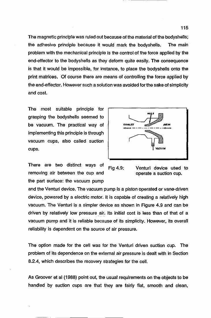
115
The magnetic principle was ruled out because of the material of the bodyshells;
the adhesive principle because it would mark the bodyshells. The main
problem with the mechanical principle is the control of the force applied by the
end-effector to the bodyshells as they deform quite easily. The consequence
is that it would be impossible, for instance, to place the bodyshells onto the
print matrices. Of course there are means of controlling the force applied by
the end-effector. However such a solution was avoided for the sake of simplicity
and cost.
The most suitable prinCiple for
grasping the bodyshells seemed to
be vacuum. The practical way of
implementing this principle is through
vacuum cups, also called suction
cups.
There are two distinct ways of
removing air between the cup and
the part surface: the vacuum pump
-=====- _. - -- -- -- - --=====-
Fig 4.9:
VACUUM
Venturi device used to operate a suction cup.
and the Venturi device. The vacuum pump is a piston operated or vane-driven
device, powered by a electric motor. It is capable of creating a relatively high
vacuum. The Venturi is a Simpler device as shown in Figure 4.9 and can be
driven by relatively low pressure .air. Its initial cost is less than of that of a
vacuum pump and it is reliable because of its simplicity. However, its overall
reliability is dependent on the source of air pressure.
The option made for the cell was for the Venturi driven suction cup. The
problem of its dependence on the external air pressure is dealt with in Section
8.2.4, which describes the recovery strategies for the cell.
As Groover et al (1988) point out, the usual requirements on the objects to be
handled by suction cups are that they are fairly flat, smooth and clean,
116
conditions necessary to form a satisfactory vacuum between the object and the
suction cup.
Although some bodyshells present surfaces with recesses and protuberances,
it is always possible to find an area of the bodyshell that satisfies the
requirements above. However the size of this area and consequently, the size
of the suction cup, could pose an operational problem, as the lift capacity of the
suction cup also depends on the effective area of the cup, as demonstrated in
Equation 4.1.
where
(4.1)
F = the force or lift capacity, N.
p = the negative pressure, N/mm2.
A = the effective area7 of the suction cups used to create
the vacuum, mm2.
Because the bodyshells are so light, weighing 17 grams in average, the
diameter of the suction cups could be as small as 5 millimetres, for producing
the necessary lift capacity. The available commercial range of suction cups is
from 8 to 400 millimetres in diameter.
4.2.3 EQUIPMENT
COMMISSIONING
CELL
AVAILABLE FOR
OF THE DECORATION
Before starting to describe the next phase of the decoration cell design, that is
the process of synthesis, it is necessary to mention the equipment that was
7 The effective area 01 the cup during operation Is approximately equal to the undelormed area detennlned by the diameter 01 the suctfon cup. lhe squashing action 01 the cup as It presses against the object would tend to make the effective area slightly larger than the undelonned area.
117
already available within the Department of Mechanical Engineering,
Loughborough University of Technology for use in the decoration cell. The
purpose in using equipment already available was to gauge the final functional
requirements of some of the components of the cell in a quick and
comprehensive manner.
An example will elucidate this approach. Looking at functional requirements of
the decoration cell, one finds that there is a need for 4 different handling
mechanisms at least: one for the loading station, one for the identification
station, one to be shared by the decoration and ins~ction stations and finally,
one for the unloading station. Before starting to design these mechanisms, it
was thought be sensible to use some of the robots available within the
Department, in order to evaluate the necessary working space for the
mechanisms, number of degrees of freedom, input/output protocols, minimum
configuration of their controllers and so forth. Moreover, there was also a
possibility that of one of the robots could turn out to be the ideal mechanism for
a specific task. The equipment available at the start of the design process of
the decoration cell was:
o PUMA 560 robot: six-degree-of freedom robot arm. Programming
language: VAL 11.
o Unimate 100 robot: four-degree-of freedom, SCARA (Selective
Compliance for Robotic Assembly) type robot arm. Programming
language: mnemonic code.
o RTX robot: six-degree-of-freedom robot arm. Programming
language: Forth.
o Bosh modular conveyor system: rectangular configuration (3 x 1
metres) with piece carriers included.

118
o MX computer based vision system: supplied by Joyce-Loebl.
The only piece of equipment whose use would bring restrictions to the cell
would be the MX vision system, as the version available was a monochrome
one. Its use would not allow the identification of colours at the identification
station or the inspection of shades of colours at. the inspection station.
Nevertheless, it was decided to continue with its use at this initial stage. The
justification for this is twofold:
o it was checked with the manufacturer that the routines written
with the monochrome version could be readily adapted for the
colour version,
o the software package supplied to Loughborough University was
a fairly open version, allowing easy adaptation of the software to
the cell needs. Obviously, this was an exceptional concession
from the manufacturer of the system, as part of a collaborative
research effort between the Department and Joyce-Loebl.
119
CONCLUSION
This chapter has presented the first two phases of the Mechatronics Design
Methodology applied to the problem of automating the process of scale model
decoration.
It is necessary to mention that for establishing the functional requirements of
some of the stations, it was necessary to explore certain design options. This
is particularly evident at the loading station.
The phase of the Mechatronics design methodology which follows Design
Requirements is Synthesis. Because of the sheer size of the writing dedicated
to the synthesis of the decoration cell, what was supposed to be Item 4.3 of
this chapter has been split into the following three chapters. The reader is
offered two routes towards understanding the synthesis of the mechatronic
decoration cell: (a)going through these chapters sequentially or (b)following the
mechanical, electronic and software synthesis of the components of the
decoration cell.
120
CHAPTER 5
MECHATRONIC DECORATION CELL:
MECHANICAL SYNTHESIS
MECHATRONIC DECORATION CELL
MECHANICAL SYNTHESIS
LOADING STATION
IDENTIFICATION STATION
SIDE-LIGHTING ARRANGEMENT
BODYSHELLS HANDLING END-EFFECTORS
RE-POSITIONING DEVICE
DECORATION STATION
THE PAINTER APPROACH
THE PEG-IN-A-HOLE APPROACH
THE REVISED PEG-IN-A-HOLE APPROACH
THE MATRIX-ON-BEL T APPROACH
INSPECTION STATION
UNLOADING STATION
THE HOLLOW MATRIX TRAY CONCEPT
THE H-SHAPED SUCTION END-EFFECTOR
122
SUMMARY
This chapter presents the mechanical design of the five component stations of
the decoration cell.
The remaining phases of the mechatronics design methodology, namely,
synthesis, analysis and optimisation, evaluation and presentation are presented
indistinctively for most of the components described in this chapter and in the
next two chapters as well. However, for some components the synthesis
analysis-optimisation cycle is explained in detail in order to stress the benefits
that Mechatronics can bring about into what would otherwise be a simple
mechanical component. Two particulary good examples of this are the side
lighting system and the re-positioning devices of the identification station.

123
5.1 LOADING STATION
The simplest mechanical solution that a designer could have chosen for this
station, would have been a chute arrangement linking the moulding machines
and the decoration cell. The bodyshells on the chute would then slide by gravity
into the cell. The result of this solution, however, would not be acceptable, as
the bodyshells would bounce back from the surface where they were dropped
and consequently, they could end up anywhere and in any orientation.
Fig 5.1:
FEEDING CHUTE
Principle of operation of the loading station.
CYLINDER A
A more ordered form of loading the bodyshells seemed to be necessary,
although the idea of having the bodyshells sliding by gravity on a chute seemed
sensible1 and should be employed if possible.
When compared with other feeding devices. such as motor driven conveyors and vibrating chutes. the gravity operated chute Is the simplest and the cheapest solution.
124
After examining a number of ways for transferring the bodyshells from the chute
into the cell, including rotary hollow drums, the mechanical configuration chosen
was a mechanism with two degrees of freedom, shown schematically in Figure
5.1. The components A and B of the mechanism are pneumatic cylinders;
cylinder A has a suction cup attached to its free end.
In the rest position, both cylinders are withdrawn. The operation of the station
Is as follows: cylinder A is actuated, positioning its end effector (suction cup)
on the roof of the bodyshell located at the bottom of the feeding chute; the
vacuum is activated, the bodyshell is picked up and cylinder A returns to its
original position, lifting the bodyshell from the chute. This allows the remaining
bodyshells to slide down, so that another one is positioned by gravity at the
bottom of the chute. Cylinder B is then activated, causing a rocking movement
on cylinder A, as it is pivoted on point P. This angular movement of cylinder
A places the bodyshell over the place where it is to be released. The vacuum
is deactivated, releasing the bodyshell into the decoration cell. Cylinders A and
8 are then returned to their initial position and the loading station is ready for
the next bodyshell.
The first design parameter to be calculated was the tilt angle a of the chute that
would enable the bodyshells to slide smoothly along it. The minimum value of
the tilt angle, amln, is calculated through Equation 5.1:
where:
amln = arctan I.L (5.1)
11 is the friction coefficient between the bodyshells and the
surface of the chute materials.
The material initially chosen for the chute was aluminium. The value of 11
between aluminium and plastic is approximately 0.25, which results in an angle
amln equal to 140• The maximum value of a was determined experimentally. For
125
angles greater than 40°, a bodyshell would tip over when it hit the bottom of the
chute. Therefore, the tilt angle for the chute was chosen to lie within the
interval:
(5.2)
The next step was to calculate the positions where the air cylinders were to be
fixed, as well as the length of the crank of the mechanism. This calculation took
into consideration two important requirements:
• the angle of contact between the suction cup and the bodyshells
had to be 90°, in order to provide for sealing of the vacuum cup.
• the bodyshells should be released perpendicular to the contact
surface of the decoration cell, in order to guarantee that they
would remain in an up-right position.
At this pOint, it was necessary to define clearly where the bodyshells should be
released to. It was found convenient to make use of the modular conveyor belt
available, as a means for mechanical integration between the loading and
identification stations. Therefore, the bodyshells would be transferred from the
feeding chute to the piece carriers of the conveyor and then conveyed to the
identification station.
The definitions that follow refer to Figure 5.2. Let P, and p. be the pOints
where cylinders A and B are attached, respectively. e is the angle of the chute
and points T and C are the pOSitions of a bodyshell over the pallet and at the
bottom of the chute, respectively. K is the length of the crank and finally, S is
a line defined parallel to the crank K. The distance between line S and the
crank K cOrresponds to the stroke of cylinder B. The strokes of both cylinders,
A and B, were chosen to be 40 millimetres.
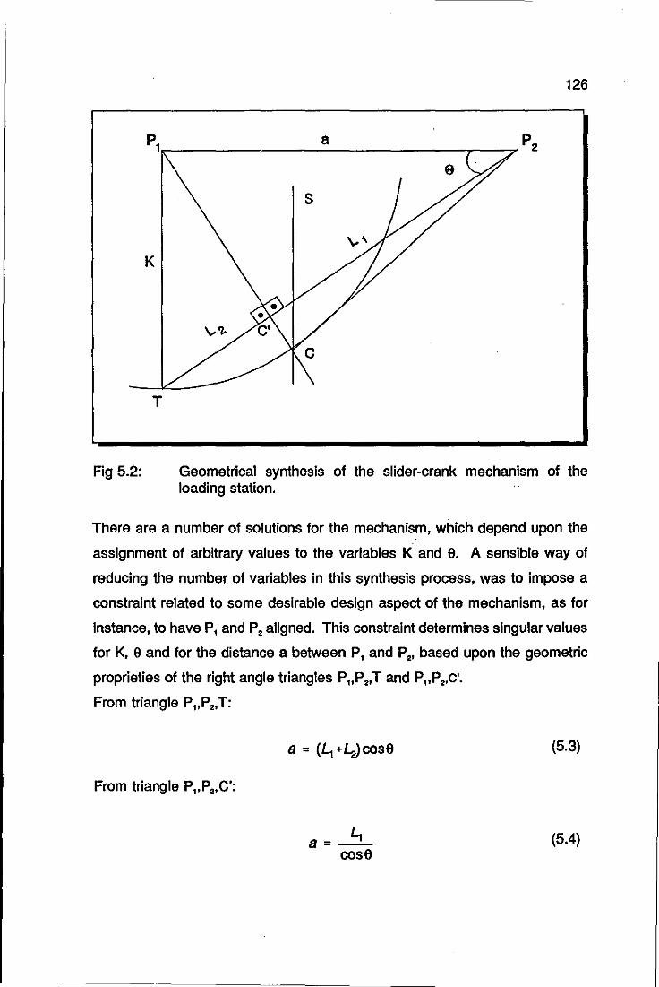
126
p1.-_______________ a ______________ -, __ ~7P2
K
T
Fig 5.2: Geometrical synthesis of the slider-crank mechanism of the loading station.
There are a number of solutions for the mechanism, which depend upon the
assignment of arbitrary values to the variables K and e. A sensible way of
reducing the number of variables in this synthesis process, was to impose a
constraint related to some desirable design aspect of the mechanism, as for
instance, to have P, and p. aligned. This constraint determines singular values
for K, 9 and for the distance a between P, and p., based upon the geometric
proprieties of the right angle triangles P"P.,T and p"p.,c'.
From triangle P"P.,T:
a = (~+4>cose (5.3)
From triangle P"P.,C':
a=~ (5.4) cose
127
Substituting Equation 5.4 into 5.5, yields:
e = arcsin( ~) ~~.
(5.5)
Finally, the value of the length of the crank is simply:
K = (~ + L.Jsine (5.6)
The values of L, and lo are determined by the choice of a particular air cylinder;
they are respectively, the cylinder stroke and the length of the body of the
cylinder. The chosen air cylinder has the following values: 40 millimetres for
L, and 165 millimetres for lo.
The value of El calculated through Equation 5.5 is 26.210 and the length of the
crank calculated through Equation 5.6, is 91 millimetres. The distance 'a'
between the pOints where the cylinders are pivoted is 184 millimetres,
calculated through Equation 5.4.
With all parameters of the mechanism determined, the next step was to
dimension its base. It was decided to clamp the base of the mechanism to the
conveyor structure, because it already had slots specially designed for the
attachment of additional components. Figure 5.3 shows the front view of latest
version of the loading station.
The base of the loading station consists of two separate inverted L shaped
sections with the feeding chute bolted in between. The chute was made long
enough to accommodate 10 bodyshells of the model2 suggested as a trial
model by Hornby Hobbies.
2 Ford Sierra, of dimensions 137 x 51 x 41 millimetres.
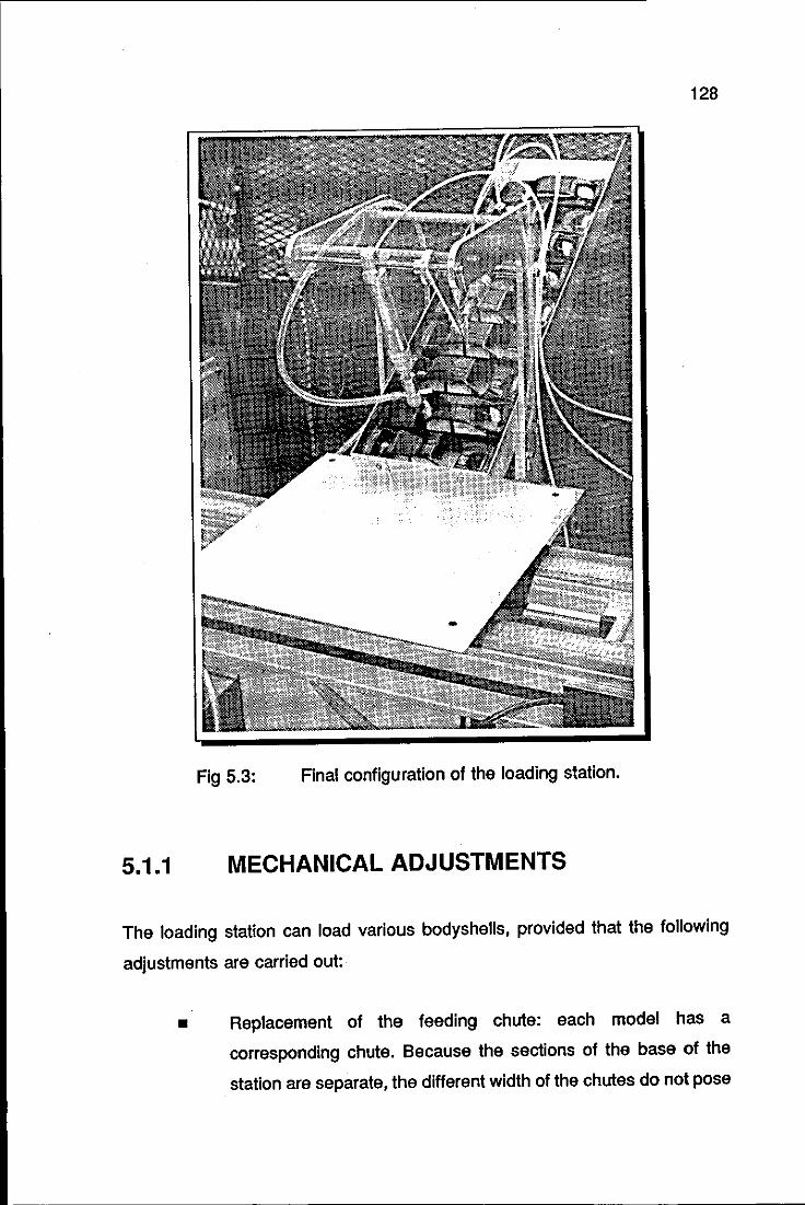
128
Fig 5.3: Final configuration of the loading station.
5.1.1 MECHANICAL ADJUSTMENTS
The loading station can load various bodyshells, provided that the following
adjustments are carried out:
• Replacement of the feeding chute: each model has a
corresponding chute. Because the sections of the base of the
station are separate, the different width of the chutes do not pose
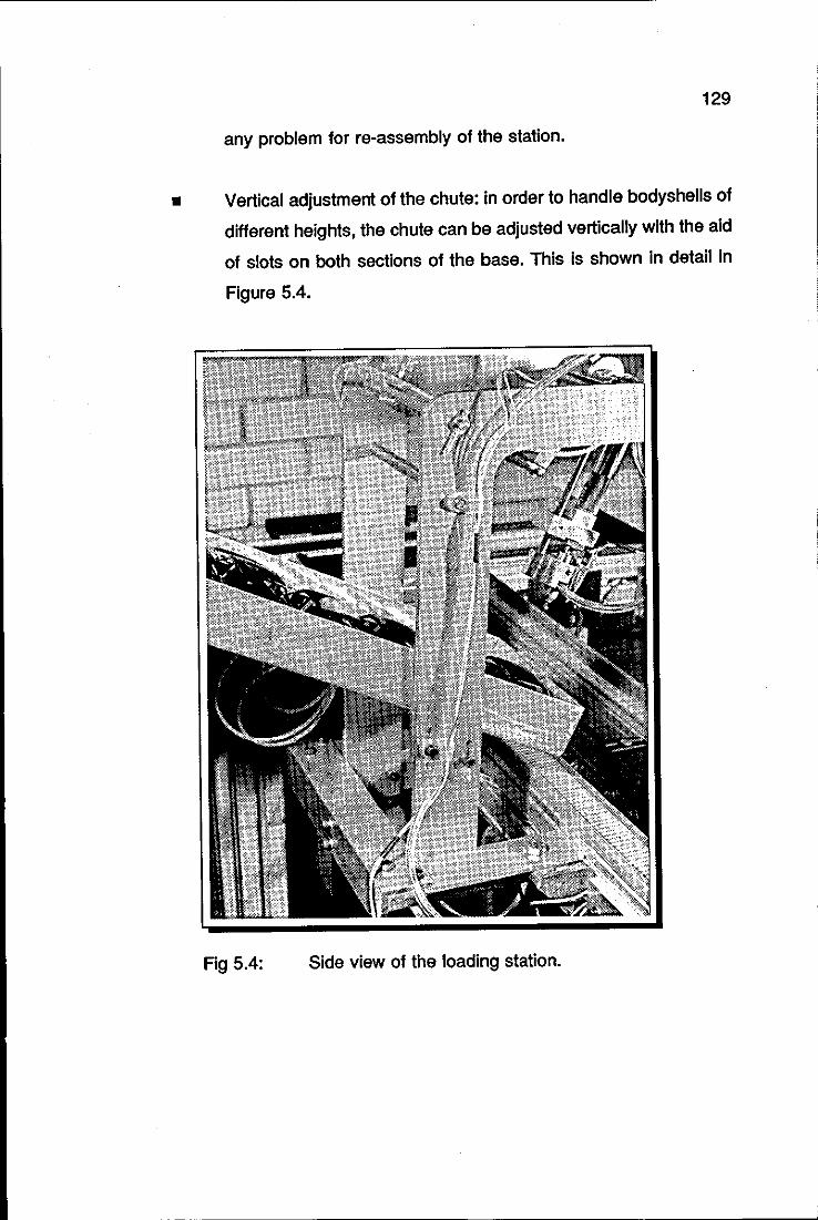
129
any problem for re-assembly of the station.
• Vertical adjustment of the chute: in order to handle bodyshells of
different heights, the chute can be adjusted vertically with the aid
of slots on both sections of the base. This is shown in detail in
Figure 5.4.
Fig 5.4: Side view of the loading station.
130
5.2 IDENTIFICATION STATION
There were two main components of the identification station to be designed,
namely, a lighting arrangement for the vision system and a mechanism for
placing the identified bodyshells onto the print matrices.
5.2.1 SIDE-LIGHTING ARRANGEMENT SYSTEM
The first problem to be tackled was to establish the necessary conditions for the
vision system to Identify successfully the bodyshells on the piece carriers of the
conveyor (or pallets, for short).
To -try to simulate as nearly as possible the factory environment of Hornby
Hobbies, all of the earlier experiments were done using overhead fluorescent
lighting, which proved to be very troublesome for the purpose of identification
of the bodyshells by the vision system, because of the reflections from the
bodyshells as well as shadows. The reflections were caused by the nature of
the models, which have a glossy finish and curved surfaces, and the shadows
by the positions of the lights relative to the camera and the mOdels themselves.
At this stage, standard industrial pallets were still being used to transport the
models. The surface of the pallets, although described as matt, was also prone
to reflection.
In an attempt to overcome these problems, the first modification to the pallets
was to insert a metal plate into the top surface, which had been bead-blasted
and sprayed matt black. This solved the problem of reflection from the pallets
but made no difference to the other problems.
Figure 5.5 shows the effects that shadows and reflections caused on an image
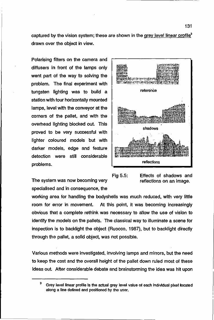
131
captured by the vision system; these are shown in the grey level linear profile3
drawn over the object in view.
Polarising filters on the camera and
diffusers in front of the lamps only
went part of the way to solving the
problem. The final experiment with
tungsten lighting was to build a
station with four horizontally mounted
lamps, level with the conveyor at the
corners of the pallet, and with the
overhead lighting blocked out. This
proved to be very successful with
lighter coloured models but with
darker models, edge and feature
detection were still considerable
problems.
The system was now becoming very
specialised and in consequence, the
Fig 5.5:
referenCe
shadows
reflections
Effects of shadows and reflections on an image.
working area for handling the bodyshells was much reduced, with very little
room for error in movement. At this pOint, it was becoming increasingly
obvious that a complete rethink was necessary to allow the use of vision to
identify the models on the pallets. The classical way to illuminate a scene for
inspection is to backlight the object (Ruocco, 1987), but to backlight directly
through the pallet, a solid object, was not possible.
Various methods were investigated, involving lamps and mirrors, but the need
to keep the cost and the overall height of the pallet down ruled most of these
ideas out After considerable debate and brainstorming the idea was hit upon
3 Grey level linear profile Is the actual grey level value of each Individual plxellocated along a line defined and positioned by the user.
132
to 'backlight' the object by an indirect means involving the shining of light into
the sides of a perspex4 block, the horizontal surfaces of which had been
specially prepared to maximise the specular reflection of the light (Trabasso et
al 1990c). Because the light sources are located at the sides of the object, the
method was called side-lighting.
Each perspex block is approximately twice the size of the original pallet and is
located on top of it by a plate which fits into a recess in the top of the pallet. It
is held in place by a single screw from underneath. The pallet is lit from the
two sides parallel to the edge of the conveyor by two.60 watt tubular bulbs. A
specially made reflector with a small opening at the front concentrates the light
into the perspex block. Because the heat generated by the bulbs is
concentrated into the edge of the perspex block, the lamps are only lit for a
short time, and just long enough for the vision system to take the picture of the
scene to be analysed.
Painting the underneath white and bead-blasting the top, has helped to sharpen
the image and using the side-lighting system, even the reflections on top of the
models do not cause problems any more. The arrangement of the side-lighting
system is shown in Figure 5.6.
Figure 5.7 shows the improvement on the quality of the image produced by the
lighting arrangement. A white bodyshell on a white background, Figure 5.7 (a),
represents the worst possible case in terms of contrast definition, but when
side-lit, a very definite shape is seen, as shown in Figure 5.7(b).
The effect of the side-lighting on the grey level profile of the bodyshell is also
shown in this figure, represented by the grey level linear profile, drawn over the
bodyshell.
4 ICI trade mark for polymethylmethaaylate.
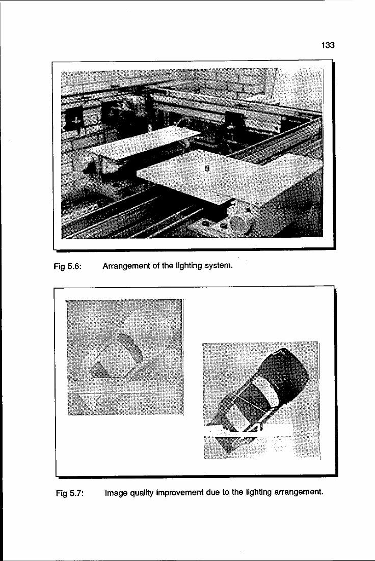
133
Fig 5.6: Arrangement of the lighting system.
Fig 5.7: Image quality improvement due to the lighting arrangement.
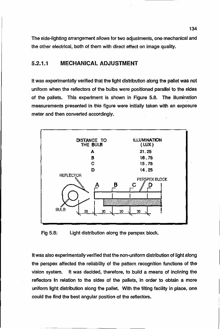
134
The side-lighting arrangement allows for two adjustments, one mechanical and
the other electrical, both of them with direct effect on image quality.
5.2.1.1 MECHANICAL ADJUSTMENT
It was experimentally verified that the light distribution along the pallet was not
uniform when the reflectors of the bulbs were positioned parallel to the sides
of the pallets. This experiment is shown in Figure 5.8. The illumination
measurements presented in this figure were initially taken with an exposure
meter and then converted accordingly.
BULB
Fig 5.8:
DISTANCE TO THE BULB
A B C D
ILLUMINATION ( LUX)
21.25 16.75 15.75 14.25
Light distribution along the perspex block.
It was also experimentally verified that the non-uniform distribution of light along
the perspex affected the reliability of the pattern recognition functions of the
vision system. It was decided, therefore, to build a means of inclining the
reflectors in relation to the sides of the pallets, in order to obtain a more
uniform light distribution along the pallet. With the tilting facility in place, one
could the find the best angular position of the reflectors.
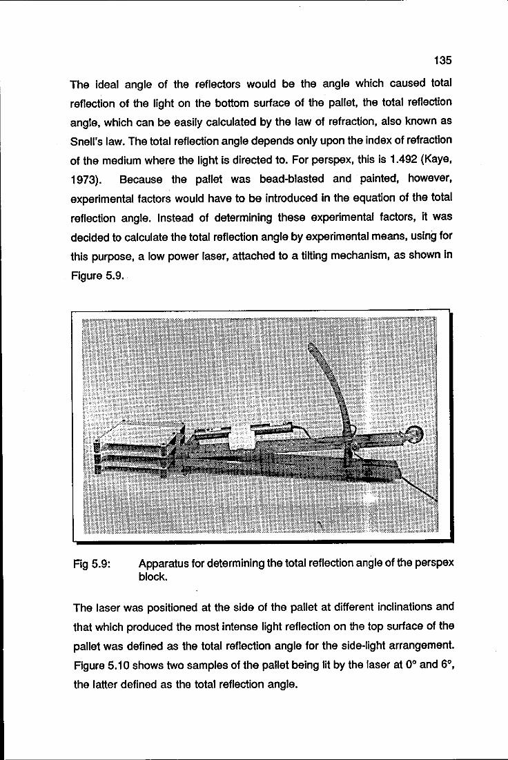
135
The ideal angle of the reflectors would be the angle which caused total
reflection of the light on the bottom surface of the pallet, the total reflection
angle, which can be easily calculated by the law of refraction, also known as
Snell's law. The total reflection angle depends only upon the index of refraction
of the medium where the light is directed to. For perspex, this is 1.492 (Kaye,
1973). Because the pallet was bead-blasted and painted, however,
experimental factors would have to be introduced in the equation of the total
reflection angle. Instead of determining these experimental factors, it was
decided to calculate the total reflection angle by experimental means, using for
this purpose, a low power laser, attached to a tilting mechanism, as shown in
Figure 5.9 ..
Fig 5.9: Apparatus for determining the total reflection angle of the perspex block.
The laser was positioned at the side of the pallet at different inclinations and
that which produced the most intense light reflection on the top surface of the
pallet was defined as the total reflection angle for the side-light arrangement.
Figure 5.10 shows two samples of the pallet being lit by the laser at 0° and 6°,
the latter defined as the total reflection angle.
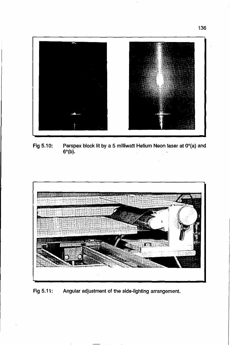
Fig 5.10:
Fig 5.11:
136
Perspex block lit by a 5 milliwatt Helium Neon laser at OO(a) and 6°(b).
Angular adjustment of the side-lighting arrangement.
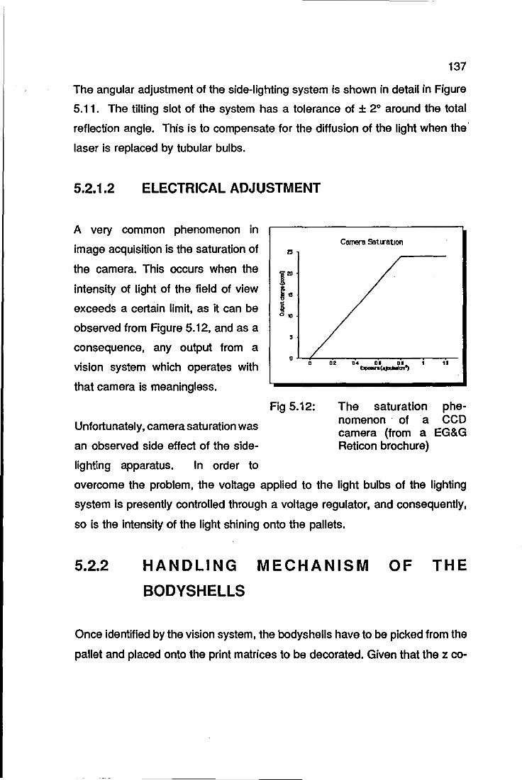
137
The angular adjustment of the side-lighting system is shown in detail in Figure
5.11. The tilting slot of the system has a tolerance of ± 2° around the total
reflection angle. This is to compensate for the diffusion of the light when the'
laser is replaced by tubular bulbs.
5.2.1.2 ELECTRICAL ADJUSTMENT
A very common phenomenon in
image acquisition is the saturation of
the camera. This occurs when the
intensity of light of the field of view
exceeds a certain limit, as it can be
observed from Figure 5.12, and as a
consequence, any output from a
vision system which operates with
that camera is meaningless.
Unfortunately, camera saturation was
an observed side effect of the side
lighting apparatus. In order to
25
I'" f" i 0"
, 0
0
Fig 5.12:
D2
CamertI SattrBtlon
D4 01 DI _c_'> • ..
The saturation phenomenon . ofa CCD camera (from a EG&G Reticon brochure)
overcome the problem, the voltage applied to the light bulbs of the lighting
system is presently controlled through a voltage regulator, and consequently,
so is the intensity of the light shining onto the pallets.
5.2.2 HANDLING MECHANISM OF THE
BODYSHELLS
Once identified by the vision system, the bodyshells have to be picked from the
pallet and placed onto the print matrices to be decorated. Given that the z co-
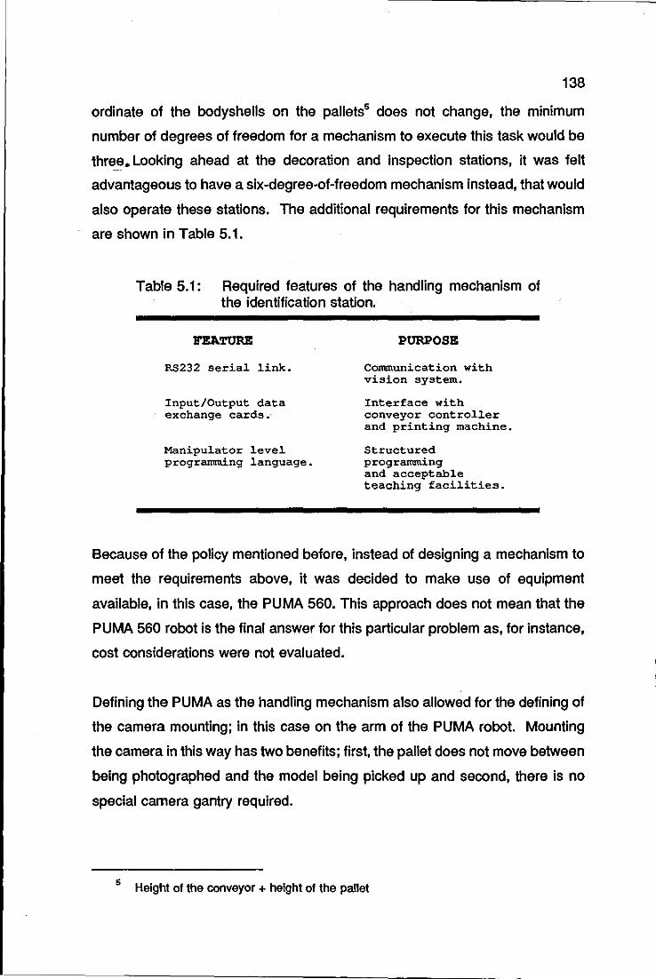
138
ordinate of the bodyshells on the pallets5 does not change, the minimum
number of degrees of freedom for a mechanism to execute this task would be
thre_e. Looking ahead at the decoration and inspection stations, it was felt
advantageous to have a slx-degree-of-freedom mechanism instead, that would
also operate these stations. The additional requirements for this mechanism
are shown in Table 5.1.
Table 5.1: Required features of the handling mechanism of the identification station.
RS232 serial link.
Input/Output data exchange cards."
Manipulator level programming language.
PURPOSE
Communication with vision system.
Interface with conveyor controller and printing machine.
Structured programming and acceptable teaching facilities.
Because of the policy mentioned before, instead of designing a mechanism to
meet the requirements above, it was decided to make use of equipment
available, in this case, the PUMA 560. This approach does not mean that the
PUMA 560 robot is the final answer for this particular problem as, for instance,
cost considerations were not evaluated.
Defining the PUMA as the handling mechanism also allowed for the defining of
the camera mounting; in this case on the arm of the PUMA robot. Mounting
the camera in this way has two benefits; first, the pallet does not move between
being photographed and the model being picked up and second, there is no
special camera gantry required.
5 Height of the conveyor + height of the pallet
139
Another design parameter that was defined as a consequence of the camera
placement, was the type of camera itself. In order to move with the robot, a
camera should be compact, robust and lightweight. These are exactly the
characteristics of the single chip, solid state CCD cameras (Charged Coupled
Device).
Defining a single handling mechanism for both, identification and decoration
station posed a requirement for a gripper changer mechanism. Without it, the
operation of picking up a bodyshell from the pallet and placing it onto a print
matrix could not be executed. The following two sections describe the gripper
changer mechanism designed for the PUMA robot and the necessary end
effectors for transferring a bodyshell from the pallet to a print matrix.
5.2.2.1 GRIPPER CHANGING MECHANISM FOR THE
ROBOT PUMA
A novel tool changing mechanism was originally designed at the Department
of Mechanical Engineering; Loughborough University of Technology, as a final
year student project (Roach, 1989). It will be referred to as dovetail changer
from now on. It differs from commercial counterparts in that the locking
mechanism is purely mechanical. This unique positive locking is achieved by
a key of double dovetail cross-section, pulled into lock and pushed out of lock
by a stand. The unit provides up to 8 pneumatic ports and up to 48 electrical
connections. It is light, 0.63 kilograms, and has a very low profile, 30
millimetres high. The claimed positional accuracy is ± 0.025 millimetres and a
payload of 10 kilograms.
The original design of the dovetail changer has received considerable
modifications in order for it to be a viable proposition for use in the decoration
cell. Before describing these modifications, a quick summary of the original
design is presented below.
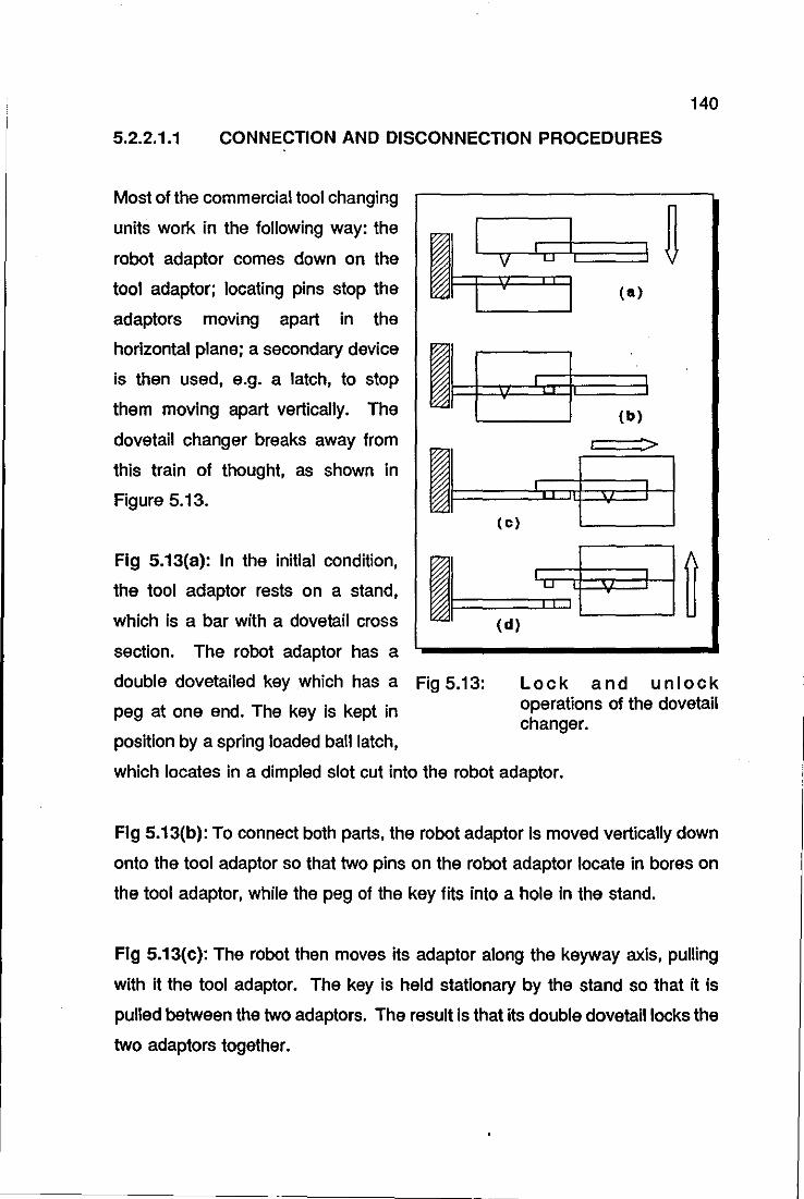
140
5.2.2.1.1 CONNECTION AND DISCONNECTION PROCEDURES
Most of the commercial tool changing
units work in the following way: the
robot adaptor comes down on the
tool adaptor; locating pins stop the
adaptors moving apart in the
horizontal plane; a secondary device
is then used, e.g. a latch, to stop
them moving apart vertically. The
dovetail changer breaks away from
this train of thought, as shown in
Figure 5.13.
I I I 'il 0 I
I I
11 I q I 0
I' •
11 I I I
"I (c)
~ Fig 5.13: Lock
~ (a)
(b)
t"z ... ~I ~
and unlock
Fig 5.13(a): In the initial condition,
the tool adaptor rests on a stand,
which is a bar with a dovetail cross
section. The robot adaptor has a
double dovetailed key which has a
peg at one end. The key is kept in
position by a spring loaded ball latch,
operations of the dovetail ch anger.
which locates in a dimpled slot cut into the robot adaptor.
Fig 5.13(b): To connect both parts, the robot adaptor is moved vertically down
onto the tool adaptor so that two pins on the robot adaptor locate in bores on
the tool adaptor, while the peg of the key fits into a hole in the stand.
Fig 5.13(c): The robot then moves its adaptor along the keyway axis, pulling
with it the tool adaptor. The key is held stationary by the stand so that it is
pulled between the two adaptors. The result is that its double dovetail locks the
two adaptors together.
141
Fig 5.13(d): Finally, the robot moves vertically upwards, so that the key of the
peg is removed from the hole in the stand.
The disconnection procedure is the reverse of that for connection.
5.2.2.1.2 INTERCHANGEABLE PNEUMATIC AND ELECTRIC PORTS
There are eight 20 millimetre diameter holes drilled in the tool changer for
pneumatic and electrical ports. These are interchangeable, so that any
combination of pneumatic and electrical parts can be assembled into the
gripper. This is also a unique feature of the dovetail changer. Some
advantages of this approach are:
• Unused ports can be left empty, giving a sizable weight saving.
Each hole cuts the weight by 20 grams.
• It is possible to design other types of ports, for instance, to carry
mains electricity, water jet, coolant supply, etc.
For the pneumatic ports, the '0' ring method is employed, resulting air lines
connections rated at 100 psi.
Regarding the electrical ports, each of them allows for six electrical lines to be
passed. It uses spring loaded probes, designed primarily for circuit board
testing. The contact resistance is 10 milliohms and the contact is capable of
carrying continuously, up to 3 milliamperes.
5.2.2.1.3
•
DOVETAIL CHANGER: MAIN FEATURES
The connection/disconnection mechanism is not pneumatically
activated, therefore it does not require an extra pneumatic line
and the associated software control.
142
• The tooling stand is smalier and less obtrusive than the stands of
the commercial units.
• One can tailor the pneumatic and electrical connections according
to the particular application to up to 8 and 48 pneumatic and
electrical connections, respectively.
• Because of its straightforward design, the tool changer can be
easily manufactured, resulting, therefore, in a low cost unit, about
one quarter of the commercial counterparts.
5.2.2.1.4 MODIFICATIONS TO THE ORIGINAL DOVETAIL CHANGER
PROJECT
When operated by the robot, the dovetail changer presented a very serious
operational problem: the movements necessary for locking or unlocking the
mechanism often resulted in the motors of the robot being stalled, as the
double dovetailed key jammed solid in the slot of the upper part of the
mechanism. Operating the mechanism by hand, it soon became obvious that
even the slightest misalignment would cause the mechanism to jam. This was
due entirely to the very tight machining tolerances on the mechanism.
The main modification to the dovetail changer was then, to increase the
tolerances between the dovetail key and the corresponding slots. This was
done by machining 1 millimetre from the base of the stand key. Even though
this solved the problem of excessive friction forces, it also jeopardised the
stability of tools on the stand, which could then rock sideways. As a trade off
between the tool stand being less obstructive than the commercial counterparts
and the capability of having the dovetail ch anger operating at all, it was decided
to assemble two support rods at each side of the original stand as a means to
support the tools in stable position. This solution proved to be successful and
the dovetail changer has been used in the cell since then.

143
Another modification to the original design of the dovetail changer was in the
electric contacts. As it stands in the original design, the electric contacts are
subject to wear and consequently, they need to be replaced after a number of
operations. The solution for overcoming this problem was to replace the
contact pins with opto-isolator diodes, with the electrical signals being
transmitted by optical rather than mechanical means. This modification is yet
to be implemented.
From his practical experience with the operation of the dovetail ch anger; the
author acknowledges two drawbaCks that would hamper the commercial
exploitation of the dovetail ch anger:
• It is extremely difficult to teach the robot the necessary locations
for the locking and unlocking manoeuvres, as this requires
alignment of the dovetail key with two of the axes of the robot tool
coordinate frame.
• Sometimes it is desirable to leave the robot tool somewhere
different from the tool stand. This is a situation very difficult to
meet with the dovetail changer, as it would require the placement
of the dovetail key at the place where the tool was to be left
Given the difficulties found in the alignment of the key at the tool
stand, this situation would only worsen in a general place.
These two drawbacks led the author to develop yet another novel tool changer
based upon the Venturi device. This tool changer is described in Chapter 9,
and is in its final operational tests. It will be referred to as mechatronic tool
changer.
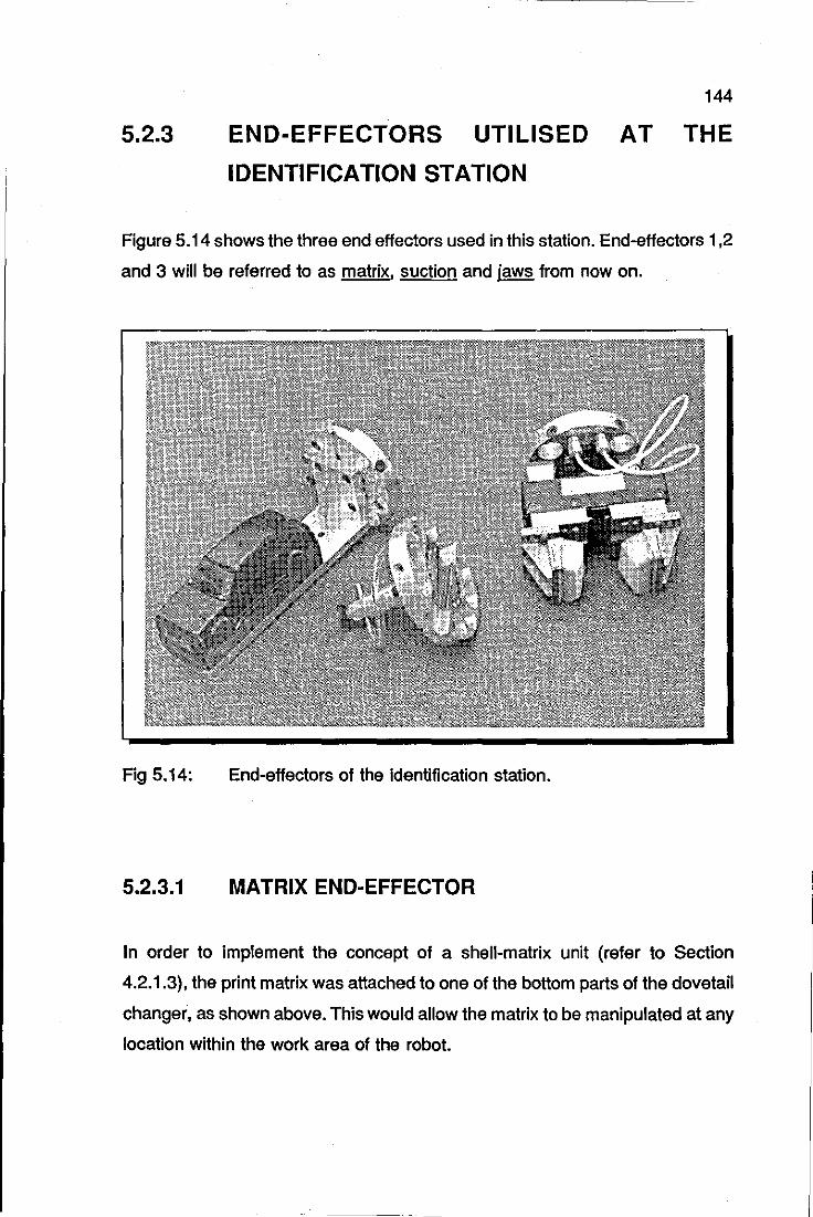
5.2.3
144
END-EFFECTORS UTILISED AT THE
IDENTIFICATION STATION
Figure 5.14 shows the three end effectors used in this station. End-effectors 1,2
and 3 will be referred to as matrix, suction and jaws from now on.
Fig 5.14: End-effectors of the identification station.
5.2.3.1 MATRIX END-EFFECTOR
In order to implement the concept of a shell-matrix unit {refer to Section
4.2.1.3}, the print matrix was attached to one of the bottom parts of the dovetail
ch anger, as shown above. This would allow the matrix to be manipulated at any
location within the work area of the robot.
145
5.2.3.2 SUCTION END-EFFECTOR
This end-effector is used to place the bodyshells onto the print matrices. This
operation could not have been done by any different means, as for instance,
a jaws end-effector would be liable to deform the bodyshells in a way that
would make their placement onto the print matrices impossible. However, the
jaws end-effector did need to be used, for the reasons pOinted out below.
The sequence of steps necessary for picking up the bodyshells from the pallets
is as follows:
i) The CCD camera mounted on the PUMA arm takes a photograph
of the scene,
ii) The scene is analysed by the vision system, which identifies the
bodyshell and sends to the PUMA the orientation angle of the
model as well as the offsets of the centre of the boundary of the
bodyshell6 from a reference position.
iii) With this information, the robot controller updates the reference
location of the bodyshell and drives the robot to pick it up.
It was noticed, however, that the suction end-effector sometimes ended up on
areas of the bodyshell unsuitable for grasping, such as windscreen, windows
or the edges of the roof, where the vacuum could not be properly created due
to lack of sealing between the suction cup and the surface. The phenomenon
observed was that the centre of the boundary of the bodyshell was moving
within the boundary of the bodyshells, following, to some extent, the different
orientation angles of the bodyshell.
6 The offsets are Initially calculated In plxels, which Is the Image unit Then, they are converted Into a unit recognisable by the robot controller through calibration factors. The calibration procedures between the vision system and the robot, which were derfved In a orfglnal manner, are presented In Section 7.2.4.
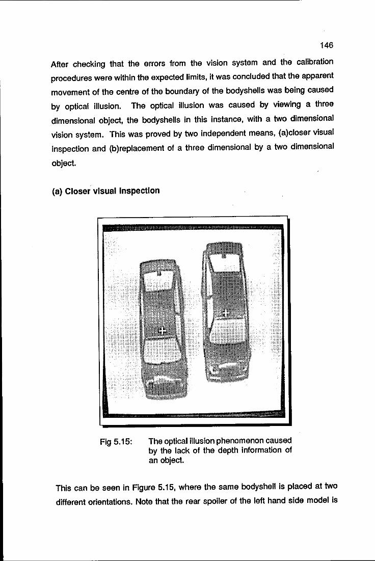
146
After checking that the errors from the vision system and the calibration
procedures were within the expected limits, it was concluded that the apparent
movement of the centre of the boundary of the bodyshells was being caused
by optical illusion. The optical illusion was caused by viewing a three
dimensional object, the bodyshells in this instance, with a two dimensional
vision system. This was proved by two independent means, (a)closer visual
inspection and (b) replacement of a three dimensional by a two dimensional
object.
(a) Closer visual Inspection
Fig 5.15: The optical illusion phenomenon caused by the lack of the depth information of an object.
This can be seen in Figure 5.15, where the same bodyshell is placed at two
different orientations. Note that the rear spoiler of the left hand side model is
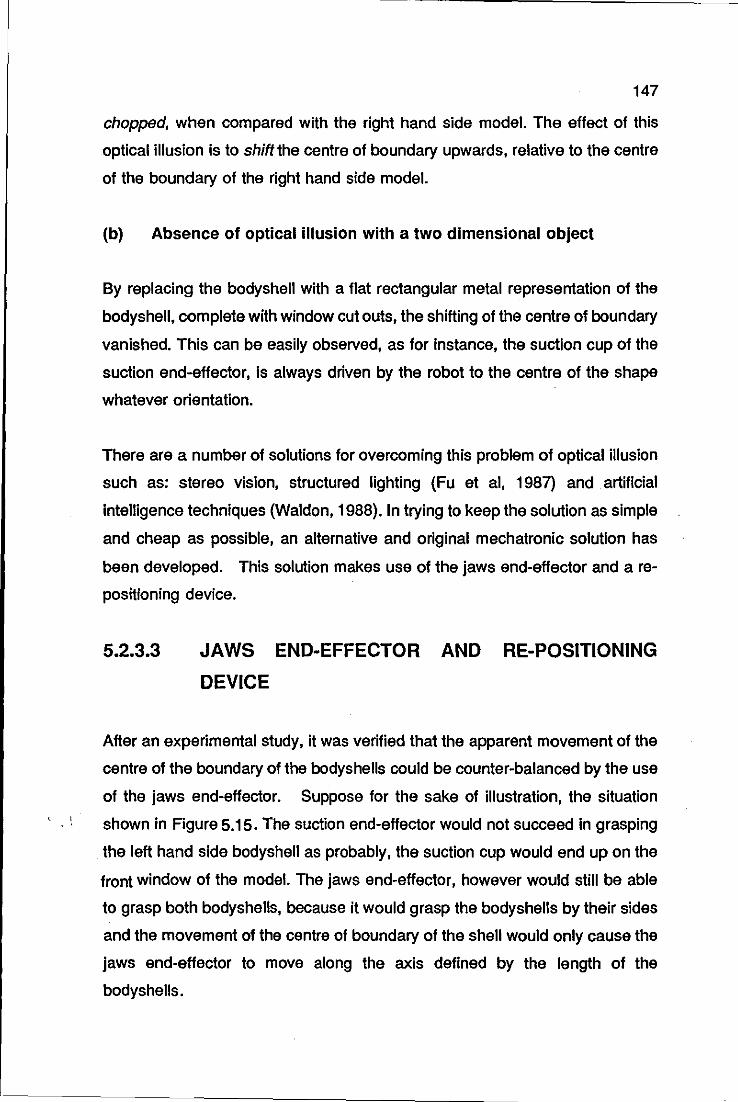
147
chopped, when compared with the right hand side model. The effect of this
optical illusion is to shift the centre of boundary upwards, relative to the centre
of the boundary of the right hand side model.
(b) Absence of optical illusion with a two dimensional object
By replacing the bodyshell with a flat rectangular metal representation of the
bodyshell, complete with window cut outs, the shifting of the centre of boundary
vanished. This can be easily observed, as for instance, the suction cup of the
suction end-effector, Is always driven by the robot to the centre of the shape
whatever orientation.
There are a number of solutions for overcoming this problem of optical illusion
such as: stereo vision, structured lighting (Fu et ai, 1987) and artificial
intelligence techniques (Waldon, 1988). In trying to keep the solution as simple
and cheap as possible, an alternative and original mechatronic solution has
been developed. This solution makes use of the jaws end-effector and a re
positioning device.
5.2.3.3 JAWS END-EFFECTOR AND RE-POSITIONING
DEVICE
After an experimental study, it was verified that the apparent movement of the
centre of the boundary of the bodyshells could be counter-balanced by the use
of the jaws end-effector. Suppose for the sake of illustration, the situation
. , shown in Figure 5.15. The suction end-effector would not succeed in grasping
the left hand side bodyshell as probably, the suction cup would end up on the
front window of the model. The jaws end-effector, however would still be able
to grasp both bodyshells, because it would grasp the bodyshells by their sides
and the movement of the centre of boundary of the shell would only cause the
jaws end-effector to move along the axis defined by the length of the
bodyshells.
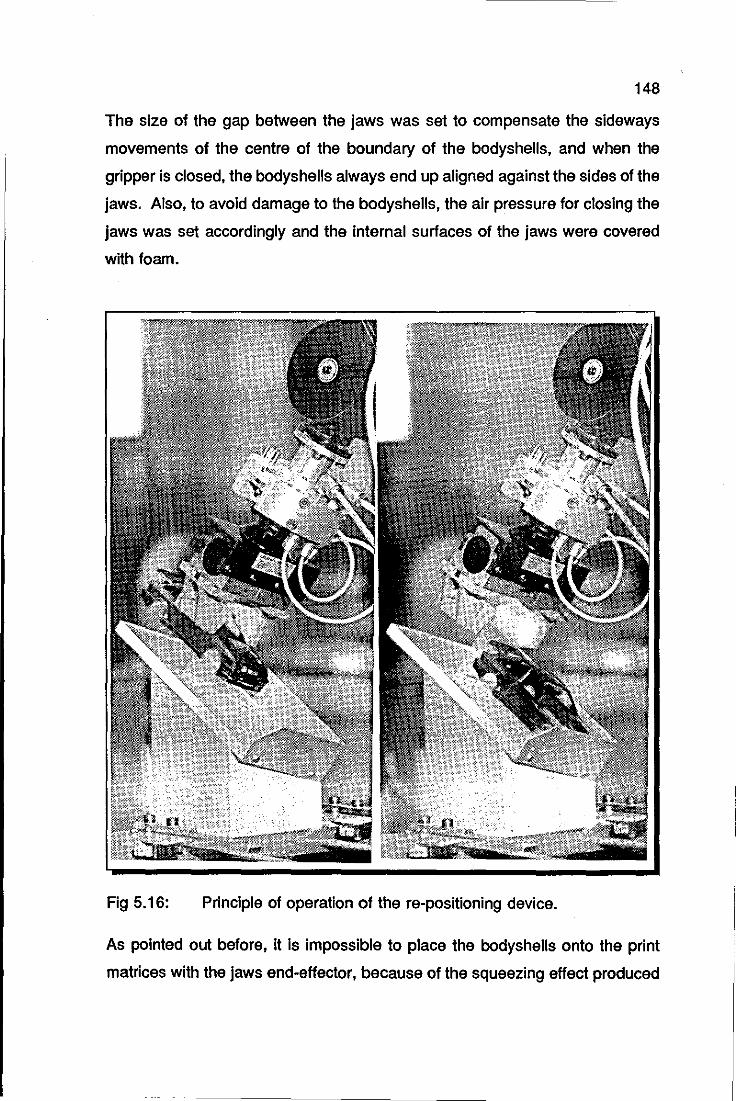
148
The size of the gap between the jaws was set to compensate the sideways
movements of the centre of the boundary of the bodyshells, and when the
gripper is closed, the bodyshells always end up aligned against the sides of the
jaws. Also, to avoid damage to the bodyshells, the air pressure for closing the
jaws was set accordingly and the internal surfaces of the jaws were covered
with foam.
Fig 5.16: Principle of operation of the re-positioning device.
As pointed out before, it is impossible to place the bodyshells onto the print
matrices with the jaws end-effector, because of the squeezing effect produced
149
by the jaws on the bodyshells. In order to replace the jaws end-effector with the
suction end-effector, the robot has to release the bodyshell to somewhere. It
was found convenient to associate with this place the property of cancelling out
the optical illusion error. This place or rather, mechanical device, will be
referred to from now on, as re-positioning device (Trabasso et ai, 1991b).
As it can be observed in Figure 5.16, the re-positioning device is an extremely
simple device. It is also very reliable as the bodyshells always end up aligned
against the sides of the device, when they are released by the robot; the
bodyshells simply slide by gravity along the bottom surface of the device.
The material of the bottom surface of
the re-positioning device is perspex
and the angles of the stand were
calculated through Equation 5.2;
naturally, \J is in this instance, the
friction coefficient between plastic
and perspex. The top surface of the
re-positioning device is initially
inclined relative to the horizontal
plane by 31 0 and then by 21 0 relative
Fig 5.17: The inclination angles of the re-positioning device.
to its bottom left corner, as shown in Figure 5.17. It is worth mentioning that
the re-positioning device also cancels out the errors from the vision-robot
calibration procedures and the vision system measurement routines.
The idea of designing the re-positioning device was arrived at, after evaluating
the effort that would be required to cancel the optical illusion error by software
or electronic means. In some mechatronic products, one can identify the
integration of the three fields as a way of aiding the achievement or
simplification of the mechanical requirements of the product, viz the autofocus
camera and the Herschell telescope. In the re-positioning device, however, this
perceptible trend is broken, as the Mechanics simplifies considerably a solution
150
that would be otherwise extremely difficult to be carried out.
Picking up the bodyshells with the jaws end-effector requires an additional
change of the end-effectors. To shorten the time required for this operation, the
re-positioning device was placed on top of the tool rack. Yet another solution
for speeding up the picking up operation was devised: the infra-red end
effector, which enhances even more the mechatronic profile of the previous
solution. The infra-red end-effector is an adaptation of the suction end-effector:
four infrared sensors are attached to it, equally spaced around the suction cup.
Its use precludes the robot from having to use the jaws end-effector and
consequently, avoids an additional operation. The infra-red end-effector Is
described In detail in Section 9.4; its operation emphasizes the benefits
achieved by an integrated mechatronic solution.
5.3 DECORATION STATION
It was said in the last section that the PUMA robot would also be used as a
handling mechanism for the decoration station. Therefore, the mechanical
design of this station aims to find the best mechanical interaction between the
pad printing machine and the PUMA robot, in order to carry out the decoration
of the bodyshells efficiently.
Examining the operation of the pad print machine, one can conclude that it
would be very difficult to try to automate in any other way the present inking
operation, as the sweeping of the ink over the plate and then, the wiping of the
excess away is basically, a straight, single plane action. Thus, the area left to
improve is that of transferring the decoration motifs from the silicone pads to
the bodyshells.
The main mechanical requirement for achieving this, is to ensure that the shell
matrix unity would always be accurately positioned under the silicone pads. Not
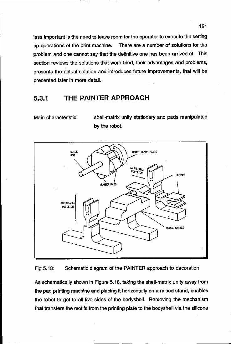
151
less important is the need to leave room for the operator to execute the setting
up operations of the print machine. There are a number of solutions for the
problem and one cannot say that the definitive one has been arrived at. This
section reviews the solutions that were tried, their advantages and problems,
presents the actual solution and introduces future improvements, that will be
presented later in more detail.
5.3.1 THE PAINTER APPROACH
Main characteristic: shell-matrix unity stationary and pads manipulated
by the robot.
Fig 5.18:
WlllE ROO
AO.lJSTA POSITION
RUBBER PAOS
ROBOT ClAI"f PLATE
OJIOES
Schematic diagram of the PAINTER approach to decoration.
As schematically shown in Figure 5.18, taking the shell-matrix unity away from
the pad printing machine and placing it horizontally on a raised stand, enables
the robot to get to all five sides of the bodyshell. Removing the mechanism
that transfers the motifs from the printing plate to the bodyshell via the silicone
152
rubber pads, gives access to the plate. It is then possible for the silicone rubber
pads to be manipulated by the robot, giving much greater freedom of
movement and placement, in that it is no longer necessary to reposition the
bodyshell every time a different area has to be decorated. This idea has been
taken a stage further in that several rubber pads are mounted on a single
holder, allowing the robot to decorate all the sides of the bodyshell in a
continuous movement (Trabasso et ai, 1990d).
To ensure the accurate placement of the motifs onto the bodyshells, it was
found to be necessary to provide some form of guiding device for the robot.
The method chosen was to fit a bar to the front face of the holder and have this
interconnected with an adjustable docking mechanism fitted to the base of the
stand, so allowing any model to be decorated on any face with one base unit.
A prototype of the robot holder was built and successfully tested as the robot
could easily get to all necessary areas of the bodyshell. For instance, for
decorating the two sides and the roof, the robot would follow a semi-circular
path centred underneath the top surface of the stand and at equally spaced
intervals of 90°, the robot would change the path from semi-circular to straight
line, for making the contact between the silicone pad and the part of the
bodyshell to be decorated. Two main drawbacks were later identified in this
approach; they are:
i) Drying time of the ink: the depth of the etched area in the printing
plate is very small, usually 0.02 millimetres; consequently, the ink tends
to dry very quickly on the rubber pads, usually around 5 seconds. This
is one of the reasons why wet-on-wet operations are possible in pad
printing. By the time the robot is picking the fourth motif from the plate,
for instance, the first one would be already dry, hence it would not be
suitable for the transferring operation. The fact that the robot moves the
pads from the printing machine to the place where the shell-matrix is
located, only adds to the problem, as the robot movement generates air
153
flow over the rubber pads, which catalyses the drying process of the ink.
ii) Placement of guiding devices at the printing plate area: the same
reason that led to the design of guiding devices for the shell-matrix unity,
that is, the insufficient robot accuracy for logo placement, also requires
the placement of guiding devices around the printing plate area, for
guaranteeing the accurate picking of the logos by the robot. This guiding
device would have to be retracted to clear the way for the movement of
the doctor blade.
There is a potential solution for problem (i), that involves alterations in the ink
characteristics, that would allow for delaying the drying time. Problem (ii),
however is more complex, with no adequate solution yet. The main difficulty is
that the printing plate area is very restricted for fitting a mechanism with the
characteristics described above; besides, it is also necessary to maintain room
for the complete removal of the printing plate in the setting operations of the
printing machine.
5.3.2 THE PEG-IN-A-HOLE APPROACH
Main characteristic: pads attached to the print machine and shell-matrix
unity manipulated by the robot.
In order to overcome problem (ii) described above, another decoration
approach was devised. In this approach, the logos are transferred to the
silicone pads as the usual operation of the pad printing machine, without any
interference from the robot.
After completing this operation, the tamping machine holds the silicone pads
in a fixed position, allowing the robot arm to push the shell-matrix unity against
the silicone pads so that the motif is transferred to the bodyshell. Figure 5.19
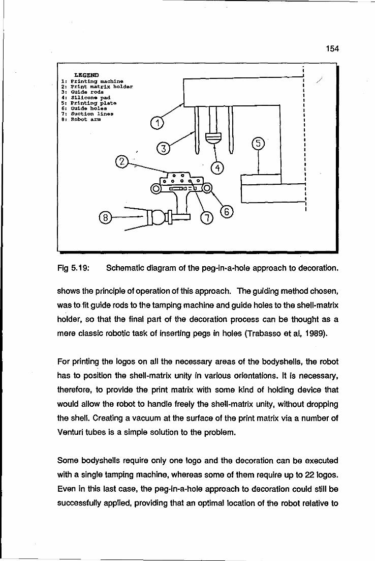
LEGEND 1 printing machine 2 Print matrix holder 3 Guide rods 4 Silicone pad 5 Printing plate 6 Guide holes 7 Suction lines 8 Robot arm
154
/
5
Fig 5.19: Schematic diagram of the peg-in-a-hole approach to decoration.
shows the principle of operation of this approach. The guiding method chosen,
was to fit guide rods to the tamping machine and guide holes to the shell-matrix
holder, so that the final part of the decoration process can be thought as a
mere classic robotic task of inserting pegs in holes (Trabasso et ai, 1989).
For printing the logos on all the necessary areas of the bodyshells, the robot
has to position the shell-matrix unity in various orientations. It is necessary,
therefore, to provide the print matrix with some kind of holding device that
would allow the robot to handle freely the shell-matrix unity, without dropping
the shell. Creating a vacuum at the surface of the print matrix via a number of
Venturi tubes is a simple solution to the problem.
Some bodyshells require only one logo and the decoration can be executed
with a single tamping machine, whereas some of them require up to 22 logos.
Even in this last case, the peg-in-a-hole approach to decoration could still be
successfully applied, providing that an optimal location of the robot relative to
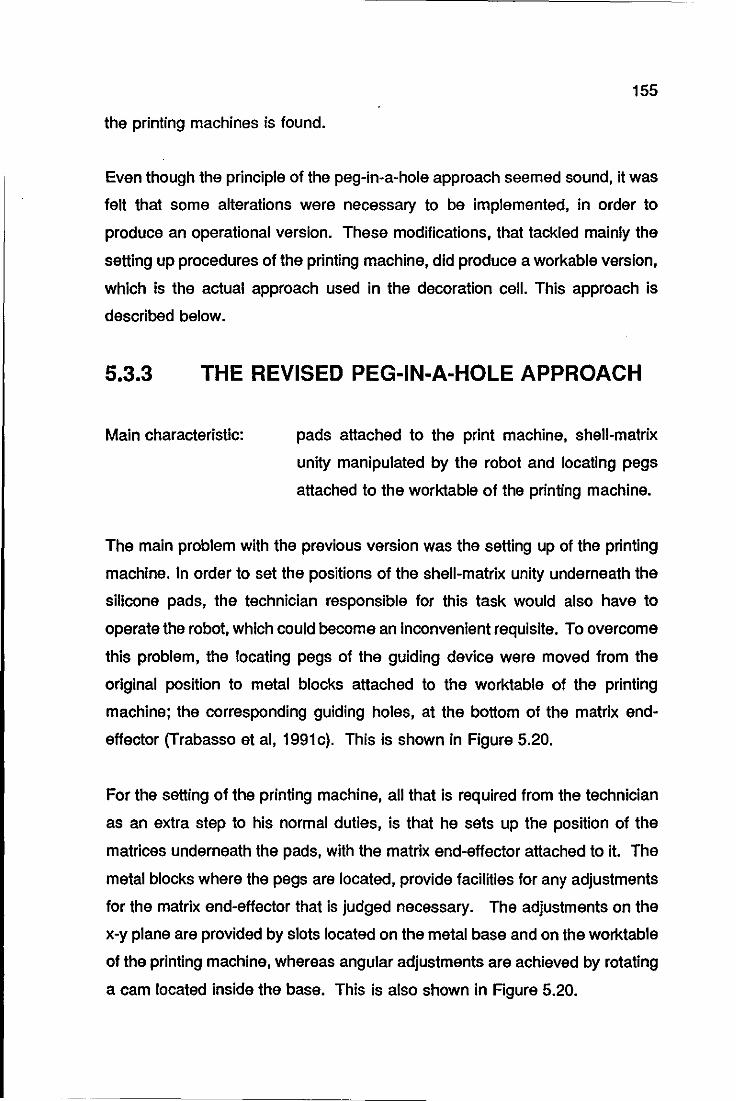
155
the printing machines is found.
Even though the principle of the peg-in-a-hole approach seemed sound, it was
felt that some alterations were necessary to be implemented, in order to
produce an operational version. These modifications, that tackled mainly the
setting up procedures of the printing machine, did produce a workable version,
which is the actual approach used in the decoration cell. This approach is
described below.
5.3.3 THE REVISED PEG-IN-A-HOLE APPROACH
Main characteristic: pads attached to the print machine, shell-matrix
unity manipulated by the robot and locating pegs
attached to the worktable of the printing machine.
The main problem with the previous version was the setting up of the printing
machine. In order to set the positions of the shell-matrix unity underneath the
silicone pads, the technician responsible for this task would also have to
operate the robot, which could become an inconvenient requisite. To overcome
this problem, the locating pegs of the guiding device were moved from the
original position to metal blocks attached to the worktable of the printing
machine; the corresponding guiding holes, at the bottom of the matrix end
effector (Trabasso et ai, 1991c). This is shown in Figure 5.20.
For the setting of the printing machine, all that is required from the technician
as an extra step to his normal duties, is that he sets up the position of the
matrices underneath the pads, with the matrix end-effector attached to it. The
metal blocks where the pegs are located, provide facilities for any adjustments
for the matrix end-effector that is judged necessary. The adjustments on the
x-y plane are provided by slots located on the metal base and on the worktable
of the printing machine, whereas angular adjustments are achieved by rotating
a cam located inside the base. This is also shown in Rgure 5.20.
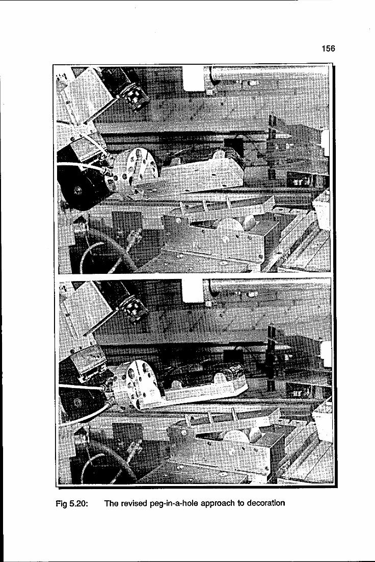
156
Fig 5.20: The revised peg-in-a-hole approach to decoration
157
Another mechanical problem to be solved in this approach was to devise a way
for the robot to position the shell-matrix unity at all necessary positions for
decoration. For the roof and bonnet, the solution is straightforward: there are
three locating pegs at the baseplate of the printing machine and three
corresponding locating holes at the bottom of the matrix gripper. For printing
the bonnet, for instance, only two pegs and two holes are matched; whereas
for printing the roof, the robot moves the matrix end-effector forward and three
pegs and three holes are then used as a guiding system.
This solution assumes that the logos for the roof and bonnet are level on the
clicM. An alternative solution would be to offset the two logos on the clicM and
as a consequence, the robot would only need to move the matrix end-effector
sideways for printing both, bonnet and roof. In this case, three pegs and three
holes would be used for guiding the matrix end-effector for print operations.
Printing on the sides of the bodyshells does not pose a problem either. The
robot would have to turn the matrix end-effector by 900 for printing the left hand
side of the bodyshell and by -900 for the right hand side and then, execute the
same routine of insertion of pegs in holes. Naturally, the guiding holes to be
used are those located at the sides of the matrix end-effector.
The difficulty in this approach is to print logos at the front and at the rear areas
of the bodyshell. Refer to Figure 4.7 for assessing the problem. The first idea
that comes to mind for solving this problem is that the shell-matrix should be
clamped to the robot by its bottom surface, in a way similar to that presented
in the previous version of this approach. It is sensible to think this way, because
the only area of the bodyshell that is never decorated is the bottom. It can be
concluded by observation, however, that such a solution would pose serious
difficulties for the setting up procedures of the printing machine as well as for
the actual printing of roof and bonnet. It was decided at this point to try an
alternative method.
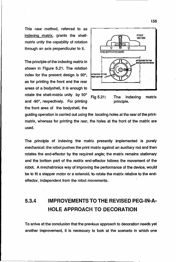
This new method, referred to as
indexing matrix, grants the shell
matrix unity the capability of rotation
through an axis perpendicular to it.
The principle of the indexing matrix in
shown in Figure 5.21. The rotation
index for the present design is 90°,
as for printing the front and the rear
areas of a bodyshell, it is enough to
rotate the shell-matrix unity by 90°
and -90°, respectively. For printing
the front area of the bodyshell, the
158
END-EFFECTOR BASE
Fig 5.21:
ATT4CHEDTOTHE ENJ\B"FeCTDR~1!
i • i • i i
The indexing matrix principle.
guiding operation is carried out using the locating holes at the rear of the print
matrix, whereas for printing the rear, the holes at the front of the matrix are
used.
The principle of indexing the matrix presently implemented is purely
mechanical: the robot pushes the print matrix against an auxiliary rod and then
rotates the end-effector by the required angle; the matrix remains stationary
and the bottom part of the matrix end-effector follows the movement of the
robot. A mechatronics way of improving the performance of the device, would
be to fit a stepper motor or a solenoid, to rotate the matrix relative to the end
effector, independent from the robot movements.
5.3.4 IMPROVEMENTS TO THE REVISED PEG-IN-A
HOLE APPROACH TO DECORATION
To arrive at the conclusion that the previous approach to decoration needs yet
another improvement, it is necessary to look at the scenario in which one
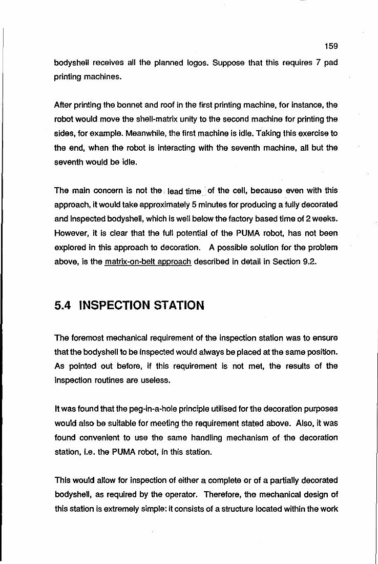
159
bodyshell receives all the planned logos. Suppose that this requires 7 pad
printing machines.
After printing the bonnet and roof in the first printing machine, for instance, the
robot would move the shell-matrix unity to the second machine for printing the
sides, for example. Meanwhile, the first machine is idle. Taking this exercise to
the end, when the robot is interacting with the seventh machine, all but the
seventh would be idle.
The main concern is not the lead time . of the cell, because even with this
approach, it would take approximately 5 minutes for producing a fully decorated
and inspected bodyshell, which is well below the factory based time of 2 weeks.
However, it is clear that the full potential of the PUMA robot, has not been
explored in this approach to decoration. A possible solution for the problem
above, is the matrix-on-belt approach described in detail in Section 9.2.
5.4 INSPECTION STATION
The foremost mechanical requirement of the inspection station was to ensure
that the bodyshell to be inspected would always be placed at the same position.
As pointed out before, if this requirement is not met, the results of the
inspection routines are useless.
It was found that the peg-in-a-hole principle utilised for the decoration purposes
would also be suitable for meeting the requirement stated above. Also, it was
found convenient to use the same handling mechanism of the decoration
station, i.e. the PUMA robot, in this station.
This would allow for inspection of either a complete or of a partially decorated
bodyshell, as required by the operator. Therefore, the mechanical design of
this station is extremely simple: it consists of a structure located within the work
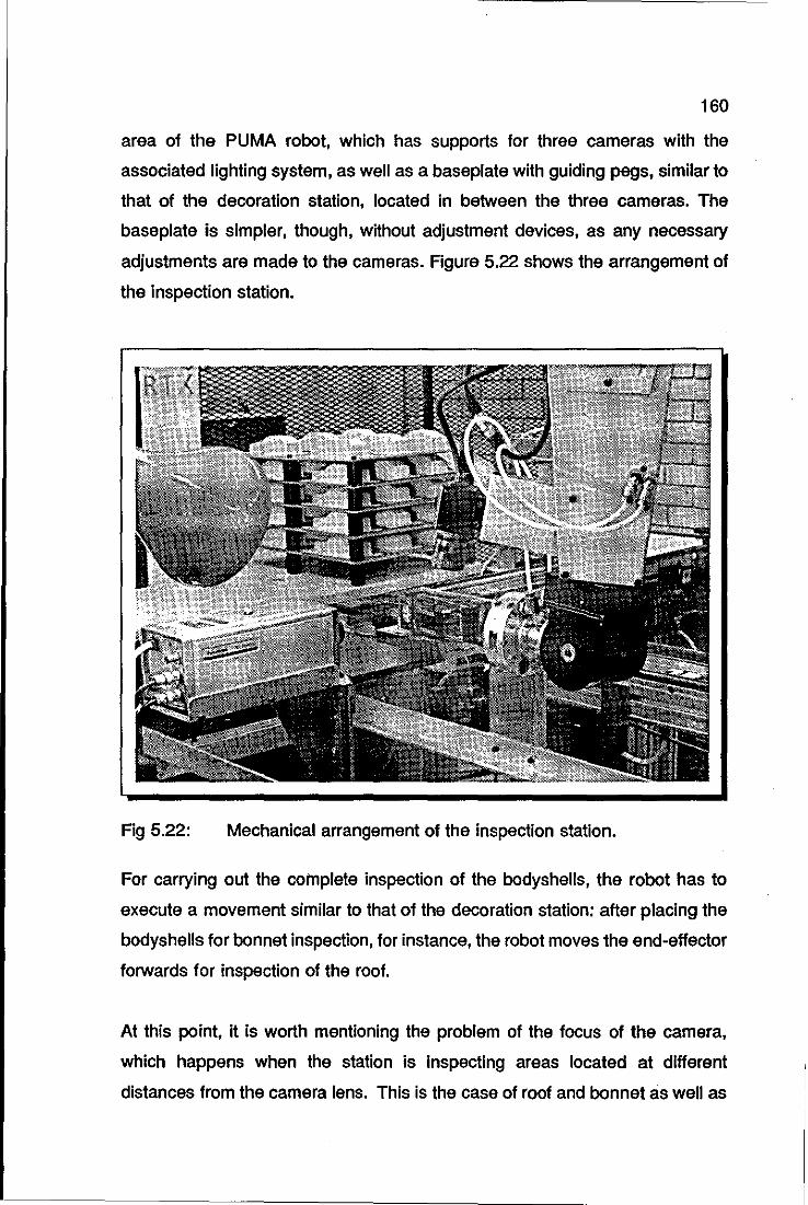
160
area of the PUMA robot, which has supports for three cameras with the
associated lighting system, as well as a baseplate with guiding pegs, similar to
that of the decoration station, located in between the three cameras. The
baseplate is simpler, though, without adjustment devices, as any necessary
adjustments are made to the cameras. Figure 5.22 shows the arrangement of
the inspection station.
Fig 5.22: Mechanical arrangement of the inspection station.
For carrying out the complete inspection of the bodyshells, the robot has to
execute a movement similar to that of the decoration station: after placing the
bodyshells for bonnet inspection, for instance, the robot moves the end-effector
forwards for inspection of the roof.
At this point, it is worth mentioning the problem of the focus of the camera,
which happens when the station is inspecting areas located at different
distances from the camera lens. This is the case of roof and bonnet as well as
161
the sides and rear/front inspections. If the focus of the camera is initially set
to inspect the roof, for instance, obviously, the bonnet will be out of focus. One
might consider a mechanical way to compensate the difference of distances
with movements of the robot: the robot would, for instance, hold the matrix end
effector higher for the bonnet inspection. The author, however, suggests a
simpler solution, which is to fit the cameras of the inspection station with
autofocus lenses. This solution comes as a suggestion, because the inspection
station was fitted with tube camera with ordinary lenses.
As the vision system available at the Department supports up to four cameras,
it was decided to share the system between the identification and the inspection
stations. The only requirement for achieving an efficient operation of the vision
system shared by the two stations, was to find an optimal sequential control for
switching cameras between the stations. This problem is addressed later.
The lighting system of the station is composed of three units of 60 Watt lamp
bulbs, each of them placed at one of the camera supports. The cameras are
placed at the station in such a way to carry out initially the inspection of the
bonnet and the first half of the sides of the bodyshells. For inspecting the roof,
and the second half of the sides, the robot moves the shell-matrix forwards. For
inspecting the front and rear areas of the bodyshells, the indexing operation of
the matrix has to be carried out first.
As it stands presently, the inspection station aims to inspect the bodyshells fully
decorated. If it is felt that a partial inspection is advantageous, the present
arrangement could then be split in three parts at least, each of them placed
next to the printing machine which is performing the part of the decoration to
be inspected.
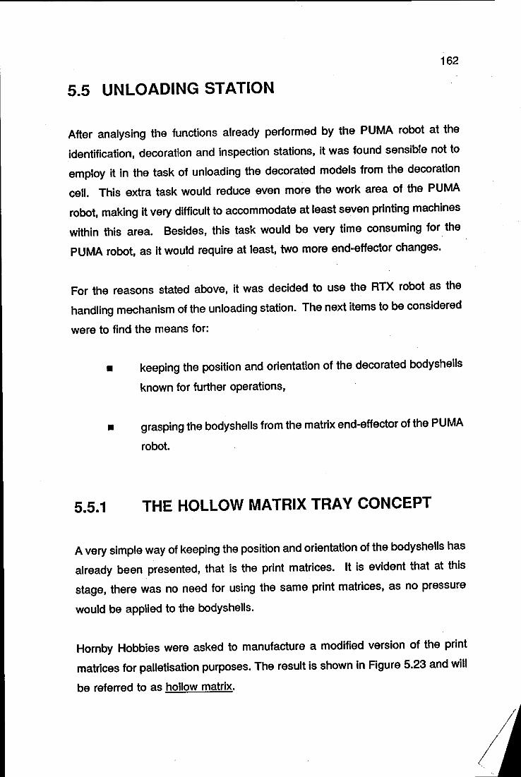
162
5.5 UNLOADING STATION
After analysing the functions already performed by the PUMA robot at the
identification, decoration and inspection stations, it was found sensible not to
employ it in the task of unloading the decorated models from the decoration
cell. This extra task would reduce even more the work area of the PUMA
robot, making it very difficult to accommodate at least seven printing machines
within this area. Besides, this task would be very time consuming for the
PUMA robot, as it would require at least, two more end-effector changes.
For the reasons stated above, it was decided to use the RTX robot as the
handling mechanism of the unloading station. The next items to be considered
were to find the means for:
5.5.1
• keeping the poSition and orientation of the decorated bodyshells
known for further operations,
• grasping the bodyshells from the matrix end-effector of the PUMA
robot.
THE HOLLOW MATRIX TRAY CONCEPT
A very simple way of keeping the position and orientation of the bodyshells has
already been presented, that is the print matrices. It is evident that at this
stage, there was no need for using the same print matrices, as no pressure
would be applied to the bodyshells.
Hornby Hobbies were asked to manufacture a modified version of the print
matrices for palletisation purposes. The result is shown in Figure 5.23 and will
be referred to as hollow matrix.
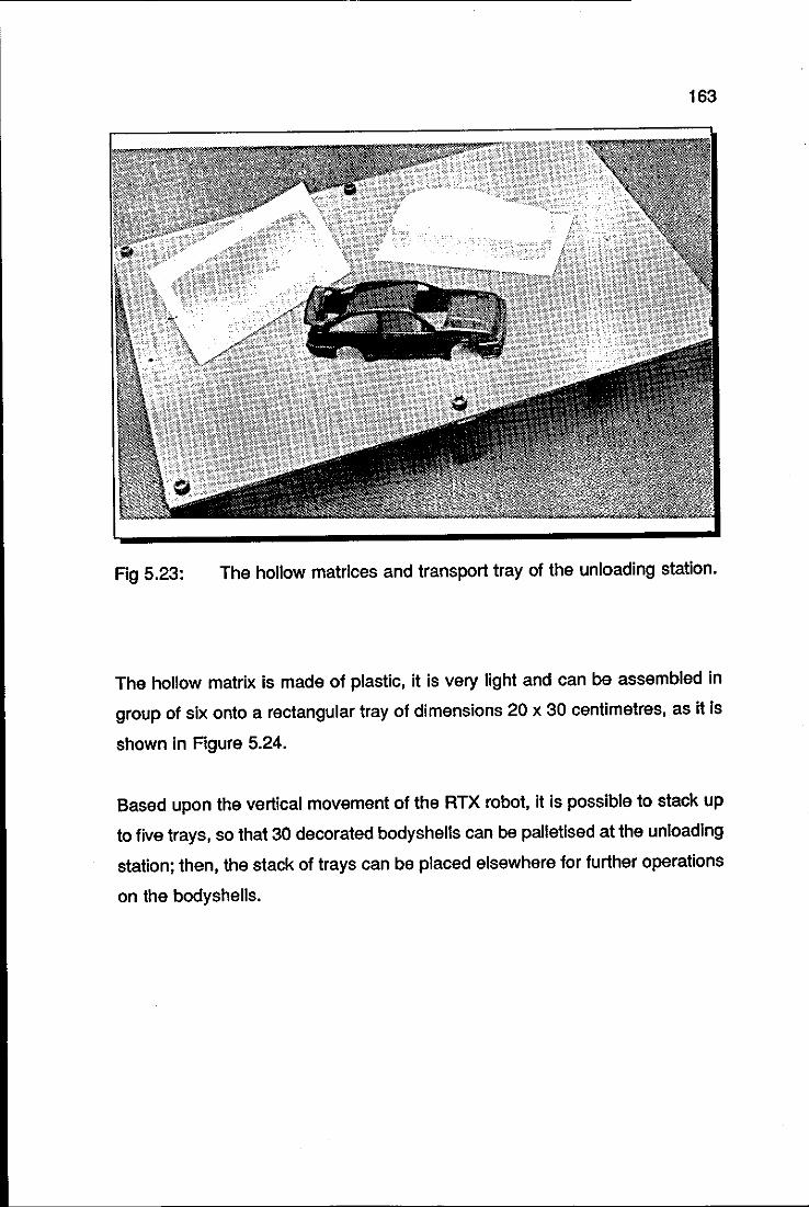
163
Fig 5.23: The hollow matrices and transport tray of the unloading station.
The hollow matrix is made of plastic, it is very light and can be assembled in
group of six onto a rectangular tray of dimensions 20 x 30 centimetres, as it Is
shown In Figure 5.24.
Based upon the vertical movement of the RTX robot, it is possible to stack up
to five trays, so that 30 decorated bodyshells can be palletised at the unloading
station; then, the stack of trays can be placed elsewhere for further operations
on the bodyshells.
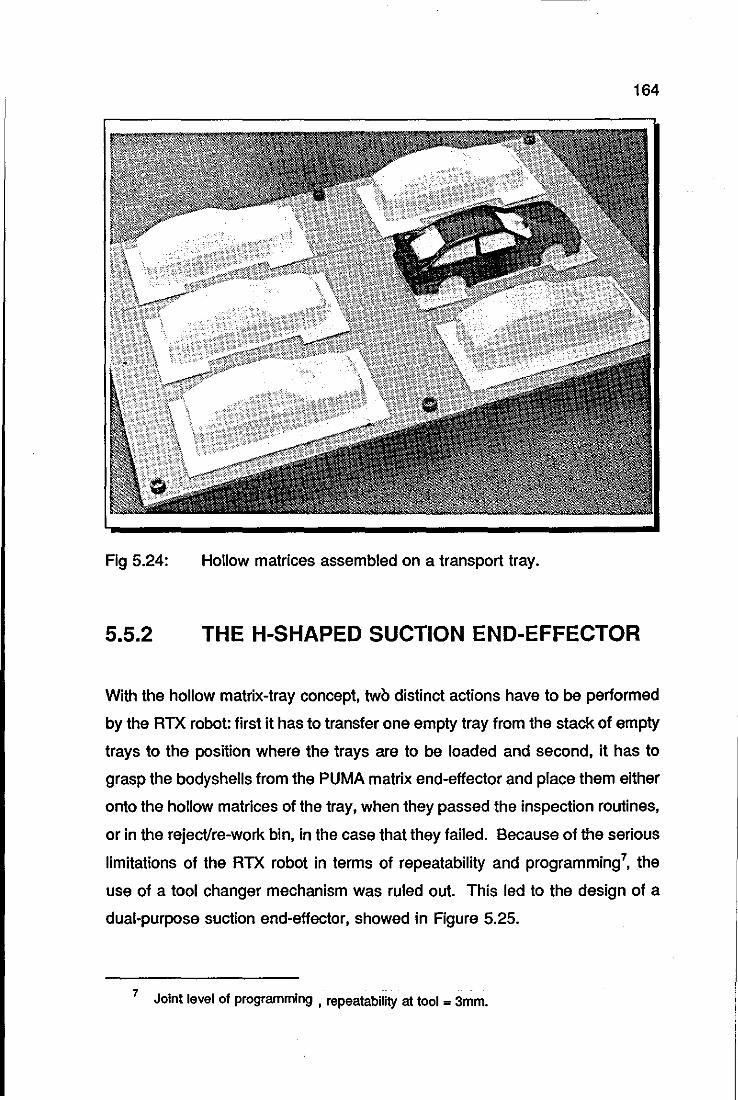
164
Fig 5.24: Hollow matrices assembled on a transport tray.
5.5.2 THE H-SHAPED SUCTION END-EFFECTOR
With the hollow matrix-tray concept, two distinct actions have to be performed
by the RTX robot: first it has to transfer one empty tray from the stack of empty
trays to the position where the trays are to be loaded and second, it has to
grasp the bodyshells from the PUMA matrix end-effector and place them either
onto the hollow matrices of the tray, when they passed the inspection routines,
or in the reject/re-work bin, in the case that they failed. Because of the serious
limitations of the RTX robot in terms of repeatability and programming7, the
use of a tool changer mechanism was ruled out. This led to the design of a
dual-purpose suction end-effector, showed in Figure 5.25.
7 ~.. . Joint level of programming , repeatabillty at tool = 3mm.
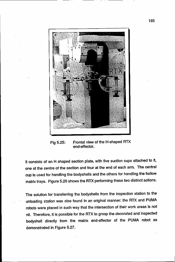
Fig 5.25: Frontal view of the H-shaped RTX end-effector.
165
It consists of an H shaped section plate, with five suction cups attached to it,
one at the centre of the section and four at the end of each arm. The central
cup is used for handling the bodyshells and the others for handling the hollow
matrix trays. Figure 5.26 shows the RTX performing these two distinct actions.
The solution for transferring the bodyshells from the inspection station to the
unloading station was also found in an original manner: the RTX and PUMA
robots were placed in such way that the intersection of their work areas is not
nil. Therefore, it is possible for the RTX to grasp the decorated and inspected
bodyshell directly from the matrix end-effector of the PUMA robot as
demonstrated in Figure 5.27.
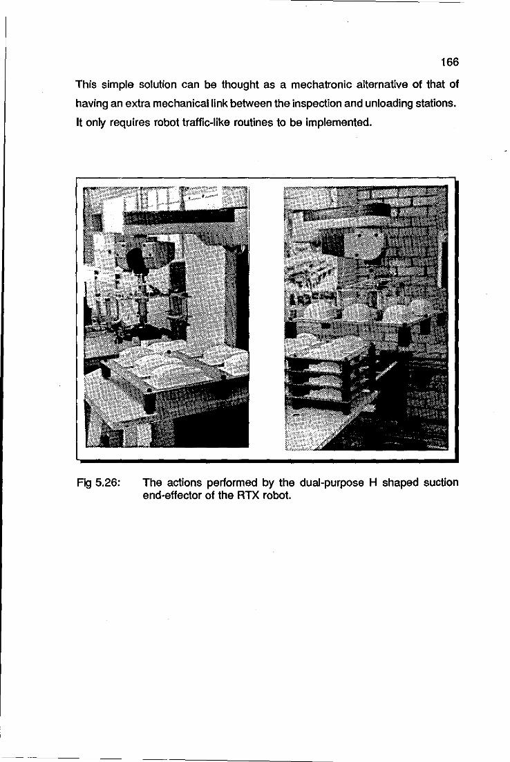
166
This simple solution can be thought as a mechatronic alternative of that of
having an extra mechanical link between the inspection and unloading stations.
It only requires robot traffic-like routines to be implemented.
Fig 5.26: The actions performed by the dual-purpose H shaped suction end-effector of the RTX robot.
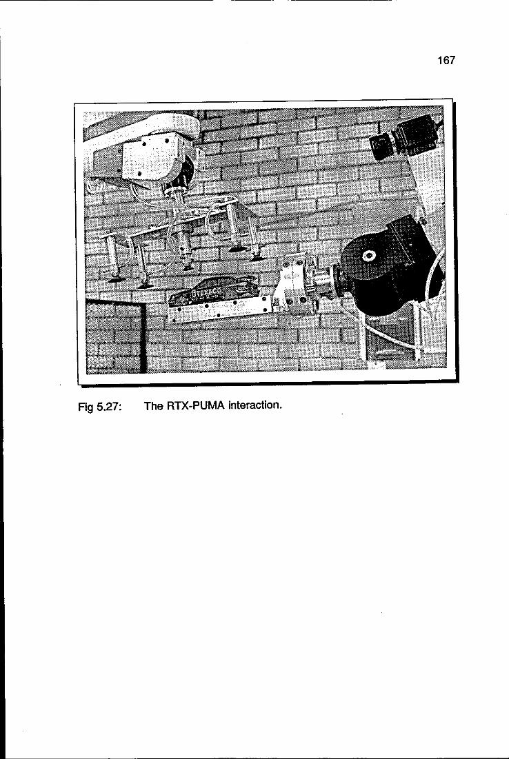
167
Fig 5.27: The RTX-PUMA interaction.
168
CHAPTER 6
MECHATRONIC DECORATION CELL:
ELECTRONIC SYNTHESIS
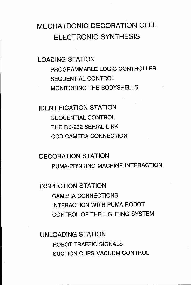
MECHATRONIC DECORATION CELL
ELECTRONIC SYNTHESIS
LOADING STATION
PROGRAMMABLE LOGIC CONTROLLER
SEQUENTIAL CONTROL
MONITORING THE BOOYSHELLS
IDENTIFICATION STATION
SEQUENTIAL CONTROL
THE RS-232 SERIAL LINK
CCO CAMERA CONNECTION
DECORATION STATION
PUMA-PRINTING MACHINE INTERACTION
INSPECTION STATION
CAMERA CONNECTIONS
INTERACTION WITH PUMA ROBOT
CONTROL OF THE LIGHTING SYSTEM
UNLOADING STATION
ROBOT TRAFFIC SIGNALS
SUCTION CUPS VACUUM CONTROL
170
SUMMARY
This chapter presents the electric and electronic design of the five component
stations of the decoration cell. It also covers the sensors and the associated
electronics employed in the stations.
Compared with the mechanical and computer software synthesis, the
electronics played a minor role. That is because most of the equipment needed
was readily available off-the-shelf, such as camera/computer interface, PLC
(Programmable Logic Controller) and most important of all, the robot
controllers. When mentioning this equipment, the author will limit the
presentation to the aspects which are only relevant for its use in the decoration
cell. Further details can be readily obtained in the suggested references.
171
6.1 LOADING STATION
The control requirements of this station are:
o stop and release the pallets at the loading position,
o execute the sequential movements of the air cylinders of the
loading mechanism,
o monitor the presence of a bodyshell at the suction cup.
It was decided to use a PLC for the first two requirements and an opto-switch
for the third. As a PLC was already being used for the conveyor system, it
was only a matter of adding extra inputs/outputs, in order to execute the control
of the loading station as well. Because the PLC is also used for control in the
identification and unloading stations as well, it will be reviewed in a general
manner in the next section. This will make it easier to describe its particular use
in the various parts of the decoration cell later on.
6.1.1 PROGRAMMABLE LOGIC CONTROLLER
(PLC)
Up to the late 60's, electromechanical relay panels constituted the standard
technique for accomplishing sequence control in industrial operations; after that
date Programmable Logic Controllers were introduced as a replacement for
them. A PLC, as a relay panel, is a device made up of multiple relays, timers
and counters; the internal wiring in a PLC, however, is executed by
programming. The PLC's are, therefore, smaller in size, more reliable and more
flexible.
According to the various manufacturers, a PLC can be defined as a digitally
operating device with programmable memory, that is capable of generating
output signals according to logic operations and other functions performed on
172
input signals. In a typical industrial operation limit, proximity or photo-electric
switches are the inputs of a PLC; the contents of a PLC program determine the
outputs which serve to control driving loads such as solenoid valves, electric
motors, lamps, electromagnetic clutches and so on. The functions that can be
accomplished by a PLC typically include:
o Control relay functions: generation of an output signal based on
logic rules applied to one or more inputs.
o Timing functions: generation, for example, of an output signal
for a specified length of time.
o Counting functions: generation of an output signal when the
value of the sum of an internal counter reaches a certain level.
o Arithmetic functions: execution of the basic arithmetic
operations such as addition, subtraction, multiplication and
division.
o Analog control functions: emulation of analog functions such as
proportional, integral and derivative control.
For the realisation of the sequential control of the various components of the
cell, the Mitsubishi Melsec F1-40MR PLC was purchased. The original number
of inputs and outputs was initially 24 and 16 respectively, later increased with
the installation of an extension unit. The combined unit presently has 48 inputs
and 32 outputs.
6.1.2 CONTROL OF THE PALLET FLOW AROUND
THE CONVEYOR
The Bosch modular conveyor system has as standard items pneumatic stop
gates and inductive proximity sensors to control the pallets around the system.
The pneumatic stop gates are electrically operated by solenoid valves. Figure
6.1 shows an example of the necessary external wiring of the PLC for the
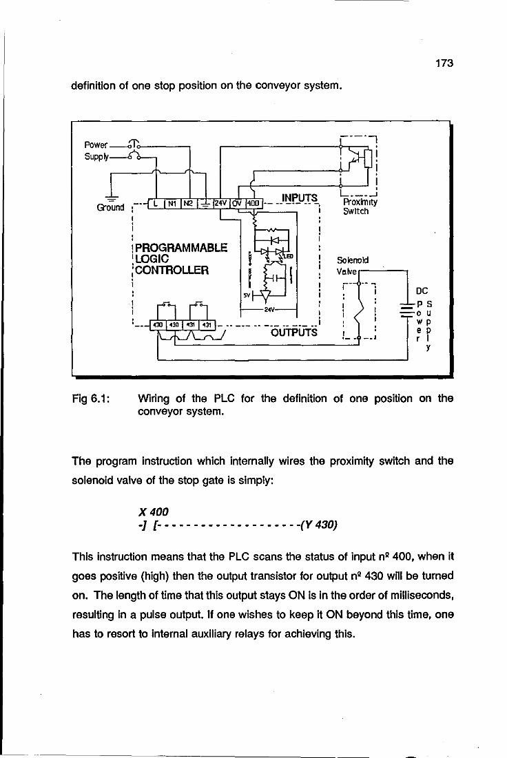
173
definition of one stop position on the conveyor system.
Q"ound
Fig 6.1:
• •
~~ __________ ~ __ ~ I L. __ ~ Proximity Switch
INPUTS L N1 N2 _ 24V av 400 -- -- --- -- -
! PROGRAMMABLE
16~~~oLLER Solenoid Vaiver-----,
• I
24V
0430 430 43t 431 _~. ___ •• _. __ • ___ ••
OUTPUTS
r- ---i DC
_ P 5 -0 u
wp e p r J
y
Wiring of the PLC for the definition of one position on the conveyor system.
The program instruction which internally wires the proximity switch and the
solenoid valve of the stop gate is simply:
X 400 -J [- - - - - - - - - - - - - - - - - - - -(V 430)
This instruction means that the PLC scans the status of input n2 400, when it
goes positive (high) then the output transistor for output n2 430 will be turned
on. The length of time that this output stays ON is in the order of milliseconds,
resulting in a pulse output. If one wishes to keep it ON beyond this time, one
has to resort to internal auxiliary relays for achieving this.
174
In addition to the wiring of the stop gates (via the associated solenoid valves)
and proximity switches which define the various fixed positions of the pallets
around the conveyor system, four more solenoid valves and proximity switches
are needed to be wired onto PLC for controlling the lift units of the conveyor.
These units serve to transport the work-piece carriers to or from the transverse
. sections of the conveyor system. The lifting action is executed by pneumatic
block cylinders under the control of solenoid valves.
Figure 6.2 shows the solenoid valves and the associated proximity switches
necessary to control all the positions of the pallets around the conveyor system.
Solenoid valve n2 433 and its associated proximity switch n2 412 control the
stopping/releasing operation of the pallets at the loading station; so do solenoid
n2431 and switch n2 414 at the identification station. The other solenoid/switch
pairs are necessary for parking the pallets while they wait to enter the stations.
6.1.3 SEQUENTIAL CONTROL OF THE LOADING
MECHANISM
For controlling the sequential action of the loading mechanism, the components
which had to be wired to the PLC are shown in Figure 6.3. The wiring is
represented in a schematic form for the sake of clarity. In this figure, SW's are
the proximity switches and SO's are the solenoid valvesl, with the following
associated functions:
o SW1: monitors the presence of the pallets at the loading station
and triggers the sequential action of the loading mechanism.
o SW2: resets the loading mechanism for the next operation.
1 This tennlnology will be used throughout the chapter.
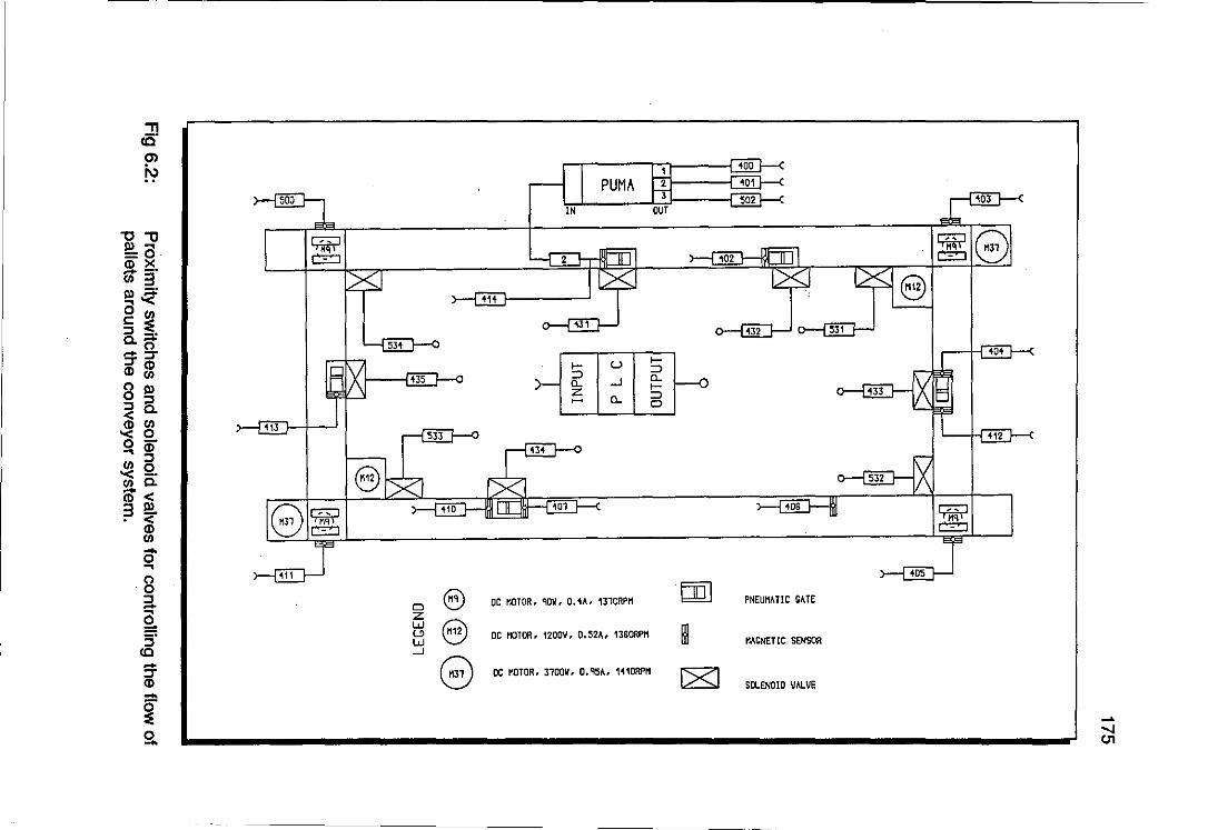
"0"0 III a CD X -_. '" 3 III _ • ... ~ o '" c: ~
~~ :::;CD (I)",
8 III :::la ~8 ... CD :::l ~ Q. ",e. m< 3Q!. . <
(I)
'" 0-... 8 ::!. 0 :i"
CC -:::; CD -~ 0 -
500
'"
8
0 @ Z
8 w '-' W -'
8
PUMA IN
2 .02
531
>- u >-=> => n. n. -' >-z a.. =>
~ 0
.0'
DC MOTOR. QOV. 0.<\". 131QRPt1 rnJ PNEUMATIC CATE
DC MOTOR. 120OV. 0.52". 13SQRPt1 ~ tlACNETlC SENSOR
DC MOTOR. 310011. D.IlSA, 1'110RPI1 C8J SOLENOID VALVE
.... " CJ1
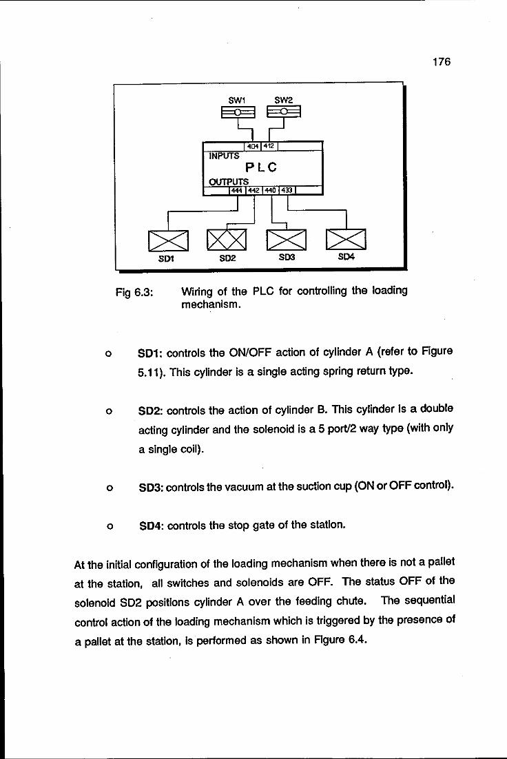
SD1
Fig 6.3:
SW1 SW2
401 412
INPUTS
PLC
Wiring of the PLC for controlling the loading mechanism.
176
o 501: controls the ON/OFF action of cylinder A (refer to Figure
5.11). This cylinder is a single acting spring return type.
o 502: controls the action of cylinder B. This cylinder is a double
acting cylinder and the solenoid is a 5 port/2 way type (with only
a single coil).
o 503: controls the vacuum at the suction cup (ON or OFF control).
o 504: controls the stop gate of the station.
At the initial configuration of the loading mechanism when there is not a pallet
at the station, all switches and solenoids are OFF. The status OFF of the
solenoid SD2 positions cylinder A over the feeding chute. The sequential
control action of the loading mechanism which is triggered by the presence of
a pallet at the station, is performed as shown in Figure 6.4.
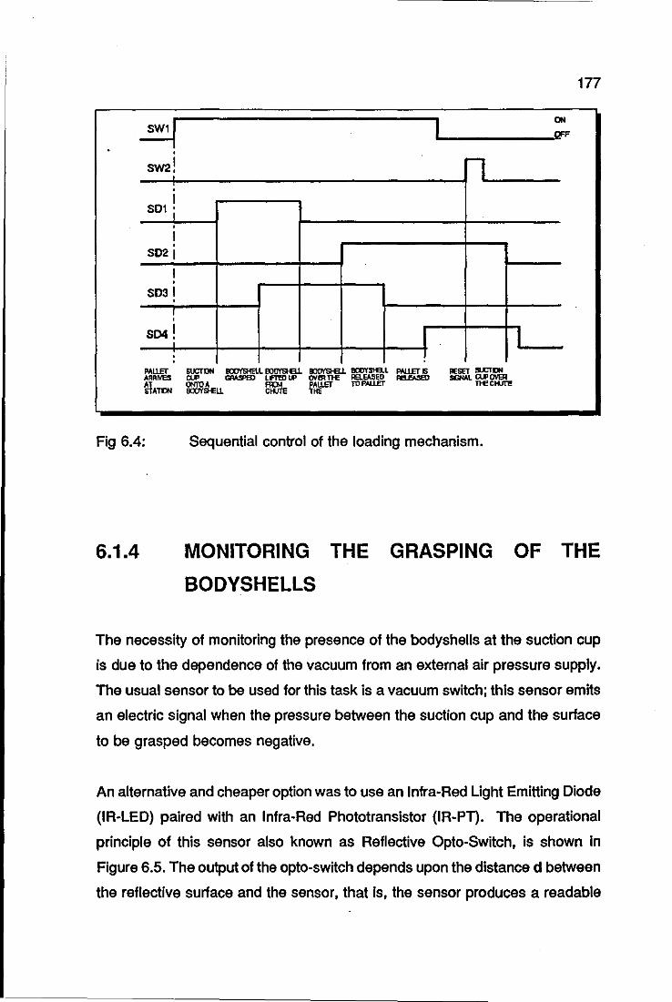
SW2 1 ~
· 1 SDI i
• 1 · SD21
1 •
S031 · !
SD4 !
PAllET ARRIVES
~'TIlII
:
Fig 6.4:
6.1.4
177
ON ..... _____ -",0fF
n
I I !
Sequential control of the loading mechanism.
MONITORING THE GRASPING OF THE
BODYSHELLS
The necessity of monitoring the presence of the bodyshells at the suction cup
is due to the dependence of the vacuum from an external air pressure supply.
The usual sensor to be used for this task is a vacuum switch; this sensor emits
an electric signal when the pressure between the suction cup and the surface
to be grasped becomes negative.
An alternative and cheaper option was to use an Infra-Red Light Emitting Diode
(IR-LED) paired with an Infra-Red Phototransistor (IR-PT). The operational
principle of this sensor also known as Reflective Opto-Switch, is shown in
Figure 6.5. The output of the opto-switch depends upon the distance d between
the reflective surface and the sensor, that is, the sensor produces a readable
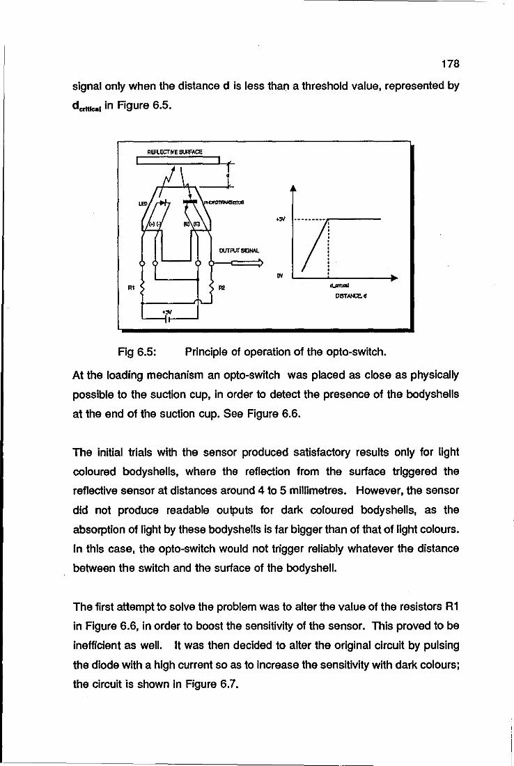
178
signal only when the distance d is less than a threshold value, represented by
dcrnlcol in Figure 6.5.
\-,"",.,,-
OlITMSGNAL
RI R2 ........ DISTNQ.d
Fig 6.5: Principle of operation of the opto-switch.
At the loading mechanism an opto-switch was placed as close as physically
possible to the suction cup, in order to detect the presence of the bodyshells
at the end of the suction cup. See Figure 6.6.
The initial trials with the sensor produced satisfactory results only for light
coloured bodyshells, where the reflection from the surface triggered the
reflective sensor at distances around 4 to 5 millimetres. However, the sensor
did not produce readable outputs for dark coloured body shells, as the
absorption of light by these bodyshells is far bigger than of that of light colours.
In this case, the opto-switch would not trigger reliably whatever the distance
between the switch and the surface of the bodyshell.
The first attempt to solve the problem was to alter the value of the resistors R1
in Figure 6.6, in order to boost the sensitivity of the sensor. This proved to be
inefficient as well. It was then decided to alter the original circuit by pulsing
the diode with a high current so as to increase the sensitivity with dark colours;
the circuit is shown in Figure 6.7.
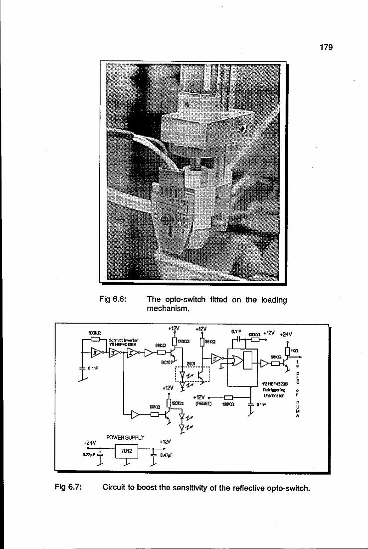
J""'
+2'\V
Fig 6.7:
Fig 6.6:
POWER SUPPLY
7812
:r:
The opto-switch fitted on the loading mechanism.
+12V +12V O.ttF mm .12V .24V
S61:!2
2601 r- ~----- --: : l' : !.- ------ . .!
0/' 12 HEf.<S2llB Retrlpoorhg .12V
+12V v---iD---i UlIvtntor
6."" t20Kn (IE;E1) lDD"" J O'rF
+12V
f '''7)<'
P L C
• r
P U M
"
Circuit to boost the sensitivity of the reflective opto-switch.
179

180
This solution proved to be successful and the reflective sensor can now be
used for all range of colours. The output of this sensor is linked to the error
recovery routines which are described later.
6.2 IDENTIFICATION STATION
The control requirements of this station are:
o stop and release the pallets at the picking up position,
o regulate the light intensity of the light bulbs of the side-lighting
arrangement,
o switch ON and OFF the light bulbs, .
o inform the PUMA robot that a bodyshell is in place to be
identified,
o establish a data protocol between the PUMA robot and the vision
system.
o connect camera to the vision system
Figure 6.8 shows the necessary components and the corresponding wiring for
the realisation of all but the last requirement stated above. In this figure, SW3
and SOS are respectively the proximity switch and solenoid valve which control
the stop/release action of the pallets at the identification station.
Note that SW3 is linked to both the PLC and PUMA robot I/O board. In fact,
this switch is powered up by the PUMA robot, as its primary function is to
inform the robot that a pallet is in place. SW3 is also linked to the PLC for the
purpose of allowing the PLC to control the parking positions of the pallets
before they arrive at the identification station.
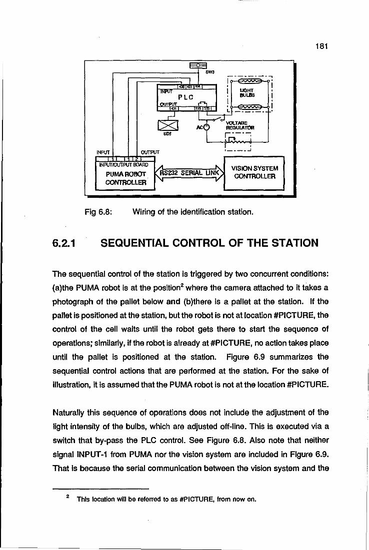
I
IINPVT PLC I OUTPUT r-,
INPlIT OVTPVT
INPlITfOlITPVT OOARD A --'"
PUMA ROBOT KRS232 SERIAL UN~) CONTROlLER " ..
--------..., I • I · I · L
· I UOHT • BULBS I
• I
- - - •
VISION SYSTEM CONTROLLER
Fig 6.8: Wiring of the identification station.
181
6.2.1 SEQUENTIAL CONTROL OF THE STATION
The sequential control of the station is triggered by two concurrent conditions:
(a)the PUMA robot is at the position2 where the camera attached to it takes a
photograph of the pallet below and (b)there is a pallet at the station. If the
pallet is positioned at the station, but the robot is not at location #PICTURE, the
control of the cell waits until the robot gets there to start the sequence of
operations; similarly, if the robot is already at #PICTURE, no action takes place
until the pallet is positioned at the station. Figure 6.9 summarizes the
sequential control actions that are performed at the station. For the sake of
illustration, it is assumed that the PUMA robot is not at the location #PICTURE.
Naturally this sequence of operations does not include the adjustment of the
light intensity of the bulbs, which are adjusted off-line. This is executed via a
switch that by-pass the PLC control. See Figure 6.8. Also note that neither
signal INPUT-1 from PUMA nor the vision system are included in Figure 6.9.
That is because the serial communication between the vision system and the
2 This location will be refelTed to as #PICTURE. from now on.
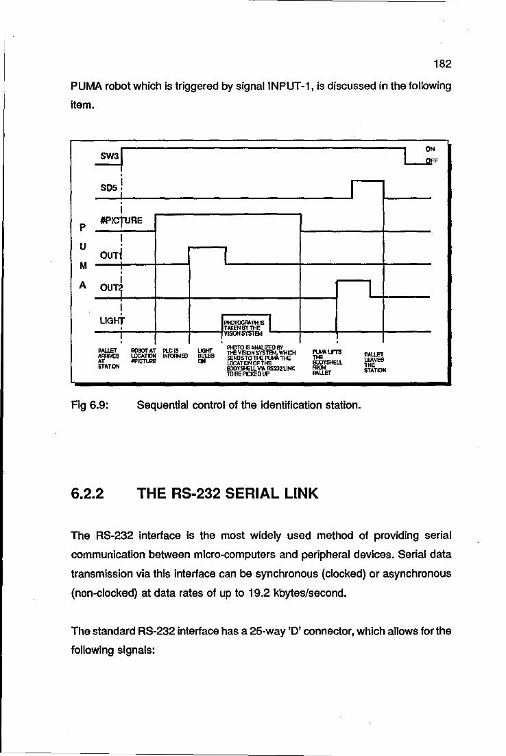
182
PUMA robot which is triggered by signal INPUT -1, is discussed in the following
item.
I sos j I · I
p
U
M
A
#PlcrURe
I · OUT~
· I OUT~
I · LIGHT
PAllET ARRIVES AT ST"TON
Fig 6.9:
6.2.2
• !
ROEOT AT PLCI5 LOCAl.,N INror:NID #PI~E
l"Hr ~s
I
!rIOTtlGRA ... " I TAKENSYTHE ! VISD/SYSTEM
PIi:lTO IS MW..IZEO BY nE VISCN S'fS1'a4.. WHCH SENDS TO nE fIU.'A nE LOCAT~OFTHE BDYSJ.ELL VIA. RS2]2l1NK 10 BE PICKEO UP
",",lm
~SHEll FROM "'LlEr
Sequential control of the identification station.
THE RS-232 SERIAL LINK
I
PALLET LEAVES THE STATION
The RS-232 interface is the most widely used method of providing serial
communication between micro-computers and peripheral devices. Serial data
transmission via this interface can be synchronous (clocked) or asynchronous
(non-clocked) at data rates of up to 19.2 kbytes/second.
The standard RS-232 interface has a 25-way '0' connector, which allows for the
following signals:
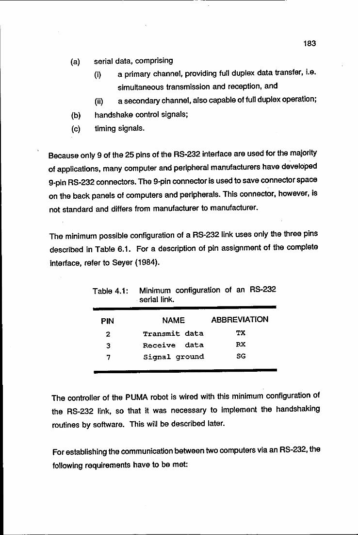
183
(a) serial data, comprising
(i) a primary channel, providing full duplex data transfer, i.e.
simultaneous transmission and reception, and
(ii) a secondary channel, also capable of full duplex operation;
(b) handshake control signals;
(c) timing signals.
Because only 9 of the 25 pins of the RS-232 interface are used for the majority
of applications, many computer and peripheral manufacturers have developed
9-pin RS-232 connectors. The 9-pin connector is used to save connector space
on the back panels of computers and peripherals. This connector, however, is
not standard and differs from manufacturer to manufacturer.
The minimum possible configuration of a RS-232 link uses only the three pins
described in Table 6.1. For a description of pin assignment of the complete
interface, refer to Seyer (1984).
Table 4.1: Minimum configuration of an RS-232 serial link.
PIN NAME ABBREVIATION
2 Transmit data TX
3 Receive data RX
7 Signal ground SG
The controller of the PUMA robot is wired with this minimum configuration of
the RS-232 link, so that it was necessary to implement the handshaking
routines by software. This will be described later.
For establishing the communication between two computers via an RS-232, the
following requirements have to be met:
6.2.3
184
(a) Physical link between the machines through an interface cable,
which can be up to 20 metres long. The major factor that limits
the length of an RS-232 transmission line is the total amount of
capacitance associated with the interface cable. High capacitance
produces disastrous effects on the wave shape of digital signals.
(b) Definition of the baud rate of the transmission,
(c) Definition of the buffer register addresses where the data which
arrives from and is sent to the transmission line is temporarily
stored.
(d) Software management of the transmission line. This software
varies from computer to computer at a high level language; for
instance, in VAL 11, which is the programming language of the
PUMA robot, there is a special set of instructions named the Z
instruction set, designed to enhance the communication abilities
of the robot. In FORTH, which is the programming language of
the RTX robot, the instructions PC@ and PCI are used for this
purpose, whereas for the vision system, these instructions are
initially written in assembly language and then used as
procedures in a higher levellanguage3 which controls the vision
system.
CCO CAMERA CONNECTION TO THE VISION
SYSTEM
Although the CCD camera connection is a straightforward procedure as can be
observed In Figure 6.10, there are three ON/OFF operating controls in the
3 Micro-Soft (MS) Pascal.
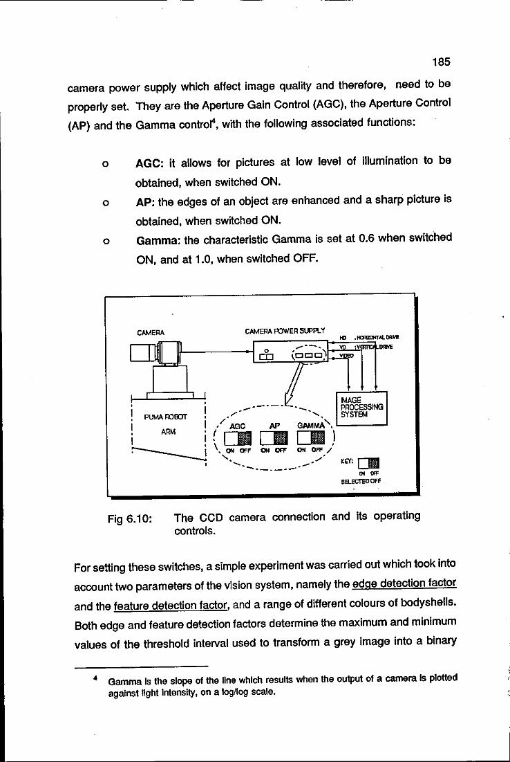
185
camera power supply which affect image quality and therefore, need to be
properly set. They are the Aperture Gain Control (AGC), the Aperture Control
(AP) and the Gamma control", with the following associated functions:
o AGC: it allows for pictures at low level of illumination to be
obtained, when switched ON.
o AP: the edges of an object are enhanced and a sharp picture is
obtained, when switched ON.
o Gamma: the characteristic Gamma is set at 0.6 when switched
ON, and at 1.0, when switched OFF.
CAMERA
PUMAROOOT
ARM
CAMERA POWER SUPPlY
MAGE / • _. ~. PROCESSING
• r , SYSTEM I '/AGC PS' GAMMA'. L-__ -'
!![]I[]I[]I) --___ I '. ON OFF OH OFF ON OFF / " ' -:~....... ._~/ KEY: rm
Fig 6.10:
'"_ .. ___ .. _ L-III
"""'" SB..ECTED OFF
The CCO camera connection and its operating controls.
For setting these switches, a simple experiment was carried out which took into
account two parameters of the vision system, namely the edge detection factor
and the feature detection factor, and a range of different colours of bodyshells.
Both edge and feature detection factors determine the maximum and minimum
values of the threshold interval used to transform a grey image into a binary
4 Gamma Is the slope of the line which results when the output of a camera Is plotted against light Intensity, on a logllog scale.
186
one. As the names suggest, the edge detection factor picks out the external
boundary of an object, whereas the feature detection factor picks out the
internal features within the external boundary, such as holes and sections of an
object which have different levels of contrast.
The experiment consisted of finding the best combinations of the camera
control switches that would keep the edge and feature detection factors
unchanged for the largest possible range of different colours of bodyshells.
Naturally, the experiment was carried out with the same level of light intensity
for all the colours. As it will become clear later, to keep the edge and feature
detection factors constant is an extremely desirable point, as it allows for
accommodating a considerable number of different shades of colours in a
single Iibrary5. The best combination of ON/OFF positions for the control
switches is also shown in Figure 6.10.
Regarding the camera synchronisation signals to the vision system, even
though they are shown as separate in this figure, VD and HD, the vision
system also allows composite synchronisation. In this case they are decoded
internally.
6.3 DECORATION STATION
The main requirement of this station was to establish the interaction between
the PUMA robot and the pad printing machine. The envisaged sequence of
events in this interaction is as follows: when the robot was not at the station,
the printing machine would always be in the inking cycle. In this cycle, the
doctor blade/spatula carrier is moving forwards and backwards; this guarantees
that the ink consistency is preserved in the ink well and also, that there is
5 In the context of computer vision, library Is a file which contains statistical data of objects used In the pattern recognition routines.
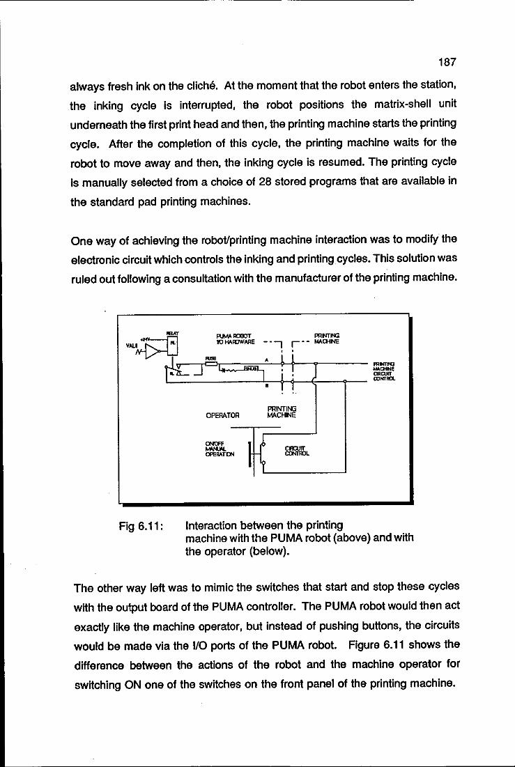
187
always fresh ink on the clicM. At the moment that the robot enters the station,
the inking cycle is interrupted, the robot positions the matrix-shell unit
underneath the first print head and then, the printing machine starts the printing
cycle. After the completion of this cycle, the printing machine waits for the
robot to move away and then, the inking cycle is resumed. The printing cycle
Is manually selected from a choice of 28 stored programs that are available in
the standard pad printing machines.
One way of achieving the robot/printing machine interaction was to modify the
electronic circuit which controls the inking and printing cycles. This solution was
ruled out following a consultation with the manufacturer of the printing machine.
feAT PlJM ROBOT PRM'"IOO VAL~ 10 HAIIJWAR. _. -, r . - """'NE
k ..... . i i
Fig 6.11:
.. ~ .t...-vv-r ..... ...,. I! I m~ L-___________ ~ l_t~~~--~-- ro~n
OPERATOR
CNOFF """"'OPERA-TeN
• ! 1
~ I I?
PRINTII'G MACHINE
'-------------'
Interaction between the printing machine with the PUMA robot (above) and with the operator (below).
The other way left was to mimic the switches that start and stop these cycles
with the output board of the PUMA controller. The PUMA robot would then act
exactly like the machine operator, but instead of pushing buttons, the circuits
would be made via the 1/0 ports of the PUMA robot. Figure 6.11 shows the
difference between the actions of the robot and the machine operator for
switching ON one of the switches on the front panel of the printing machine.
I
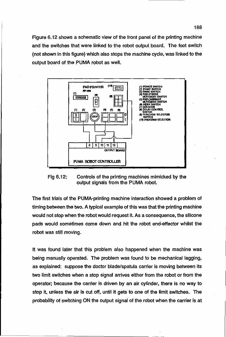
188
Figure 6.12 shows a schematic view of the front panel of the printing machine
and the switches that were linked to the robot output board. The foot switch
(not shown in this figure) which also stops the machine cycle, was linked to the
output board of the PUMA robot as well.
Fig 6.12:
PAD PRINTER ("J'I191tlI !i roNER _leH STARTSWfTCH FP2111 PANIC cwtTCH
(1) (11
~m~ PADSTRIJI<E
I-I IrOiEMENT SWITCH
[ill (S) PADCAMACE KJYeMENTSWITCH
(S) INDEX SWITCH = (7)CCUNTER (1) (2' (3) 141 (S) till (8) DELAY 00NtR0L
SWITCH
ltE[ JI~'IB881~ (t) RJNCTlOht SELECTOR &W1TCH
(10) I'IIOGAAN SELECTOR
~II~ IBI91101111121
0lITPUT IIClAR)
PUMA ROBOTCONTROLLER
Controls of the printing machines mimicked by the output signals from the PUMA robot.
The first trials of the PUMA-printing machine interaction showed a problem of
timing between the two. A typical example of this was that the printing machine
would not stop when the robot would request it. As a consequence, the silicone
pads would sometimes come down and hit the robot end-effector whilst the
robot was still moving.
It was found later that this problem also happened when the machine was
being manually operated. The problem was found to be mechanical lagging,
as explained: suppose the doctor blade/spatula carrier is moving between its
two limit switches when a stop Signal arrives either from the robot or from the
operator; because the carrier is driven by an air cylinder, there is no way to
stop it, unless the air is cut off, until it gets to one of the limit switches. The
probability of switching ON the output signal of the robot when the carrier is at
189
one of the limit switches, is very low.
The solution to this problem was to connect the outputs of the limit switches to
the input board of the robot as well. This way, the stop signal can be
maintained until one of the limit switches has been activated.
6.4 INSPECTION STATION
The control requirements of the station are:
6.4.1
o camera connections to the vision system,
o interaction with the PUMA robot for selecting the various parts of
the bodyshell to be inspected.
o communication with the unloading station.
CAMERA CONNECTIONS TO THE VISION
SYSTEM
Because this station shares the same vision system used by the identification
station, the realisation of this item was very simple. It was decided to use three
tube cameras instead of CCO cameras, because the way the station was
designed did not require any movement of the cameras. All the movements
necessary for selecting the various areas of the bodyshell to be inspected are
provided by the robot. Besides, the tube cameras are cheaper then the CCO
ones, at an average rate of 3/1. The tube cameras do not need a special
power supply or control adjustments; they are plugged straight into the mains.
The synchronisation inputs are separate, horizontal and vertical, as in the CCO
camera of the identification station.
190
6.4.2 INTERACTION WITH THE PUMA ROBOT
At the inspection station, the movements of PUMA robot are executed under
the supervision of the vision system. For example, after analysing the bonnet
and part of the sides of the bodyshell, the vision system requests the robot to
move the matrix unit forwards. The robot in its turn replies to the vision system
Informing that the matrix has been re-positioned, everything is in place for the
second shot, and so on. All the communication between the vision system and
the PUMA robot is via the RS-232 serial link.
6.4.3 COMMUNICATION WITH THE UNLOADING
STATION
The results of the inspection routine, either passed or failed. and the model
type are transmitted to the unloading station via the RS-232 serial link. This is
done through the PUMA robot controller, i.e. the vision system sends the
results of the inspection to the PUMA robot first, which in its turn, transmits
them to the controller of the RTX robot at the unloading station. The reason for
this rather tortuous path is that there was only one RS-232 port supplied with
the vision system.
6.5 UNLOADING STATION
There are two requirements for this station, namely,
o movement interaction between the RTX and PUMA robots,
o ON/OFF control of the five suction cups of the H-shaped end
effector of the RTX robot.
191
6.5.1 ROBOT TRAFFIC SIGNALS
These signals are necessary to synchronise the movements of the RTX and
PUMA robots, as their workspaces overlap. For instance, it is necessary to
guarantee that the RTX robot would move from its stand by position, only after
the PUMA robot had left the unloading station. All the necessary traffic signals
are sent through the RS-232 serial line which links the two robot controllers.
6.5.2 SUCTION CUPS VACUUM CONTROL
It was found convenient to execute this control via the PLC, as all that Is
needed is to control the solenoid valves linked to the suction cups. It was
initially tried to control the five suction cups of the H-shaped end-effector with
only one solenoid valve. This solution worked well for the transport of the
palletising trays from one stack to another, as all five suction cups were
involved in the task of grasping the trays.
For grasping the bodyshells, however, this solution proved inefficient. At the
time that the central suction cup was being used for grasping a bodyshell, the
other four were just letting air escape, as there was no surface beneath them,
and consequently, no sealing of the cup was possible. The air leakage from the
peripheral cups dropped the air pressure at the central cup to a level that was
insufficient for the generation of the necessary vacuum for grasping the
bodyshells.
The solution for this problem was to split the vacuum control of the suction cups
into two independent solenoid valves, one for controlling the central cup and the
other for the outer four cups.
Figure 6.13 shows the necessary electric and electronic links necessary to
operate the unloading station.
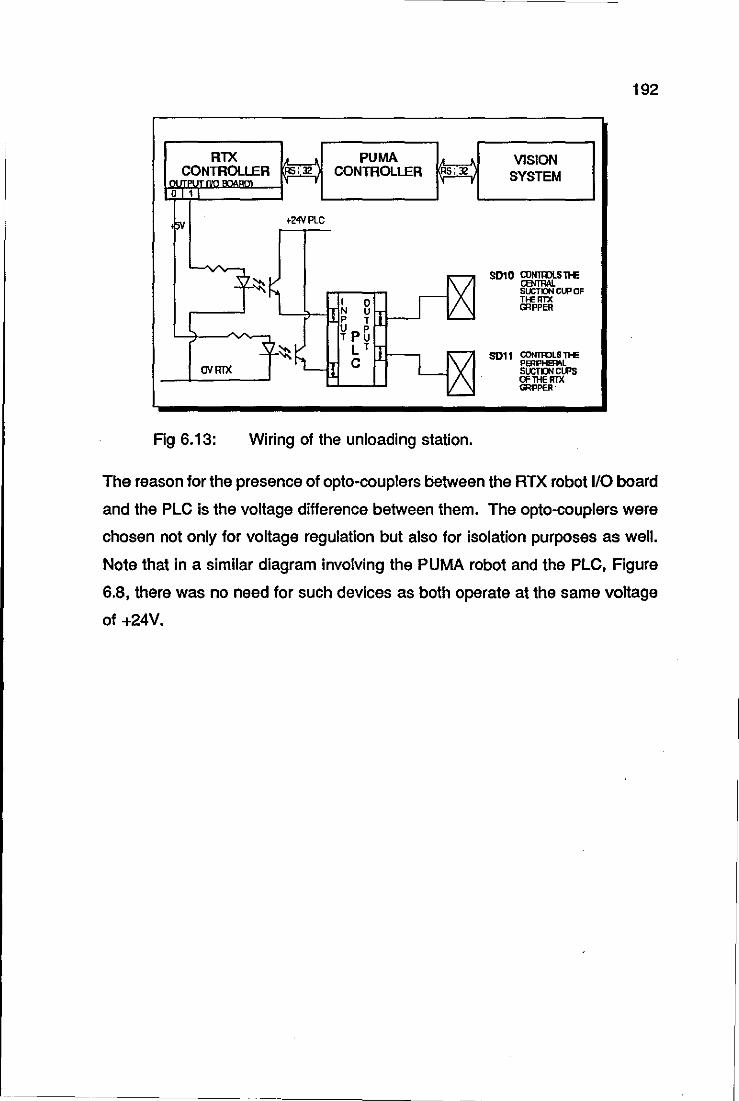
192
RlX PUMA • VISION no £?NTROLLER 1=5: 32 CONTROLLER RS; 12 SYSTEM , ,
I' ,
o I 1
5V +24VPLC
, 7' ilZ SOlO CONTIDLSll-E
- '-~ cemw. SUCTDN CLP OF
I 0 TfE Rn< N U mpPER
P TLL
¥p~ .:s ~~~ LT fT
L[X SOl1 CONTRJLS T>E
rNllIX C PmPHSIfIL su:n:w ClPS a'lHERIX GRPPER"
'--
Fig 6.13: Wiring of the unloading station.
The reason for the presence of opto-couplers between the RTX robot 110 board
and the PLC is the voltage difference between them. The opto-couplers were
chosen not only for voltage regulation but also for isolation purposes as well.
Note that in a similar diagram involving the PUMA robot and the PLC, Figure
6.8, there was no need for such devices as both operate at the same voltage
of +24V.
-----
193
CHAPTER 7
MECHATRONIC DECORATION CELL:
SOFTWARE SYNTHESIS '

MECHATRONIC DECORATION CELL
SOFTWARE SYNTHESIS
LOADING STATION
THE ON-LINE SOFTWARE
IDENTIFICATION STATION
THE MAGISCAN VISION SYSTEM
TRAINING PROCESS
THE PROBE CALIBRATION APPROACH
OFF-LINE ASSESSMENT
THE ON-LINE SOFTWARE
DECORATION STATION
THE ON-LINE SOFTWARE
INSPECTION STATION
INSPECTION DATABASE
DATABASE ASSESSMENT
THE ON-LINE SOFTWARE
UNLOADING STATION
THE ON-LINE SOFTWARE
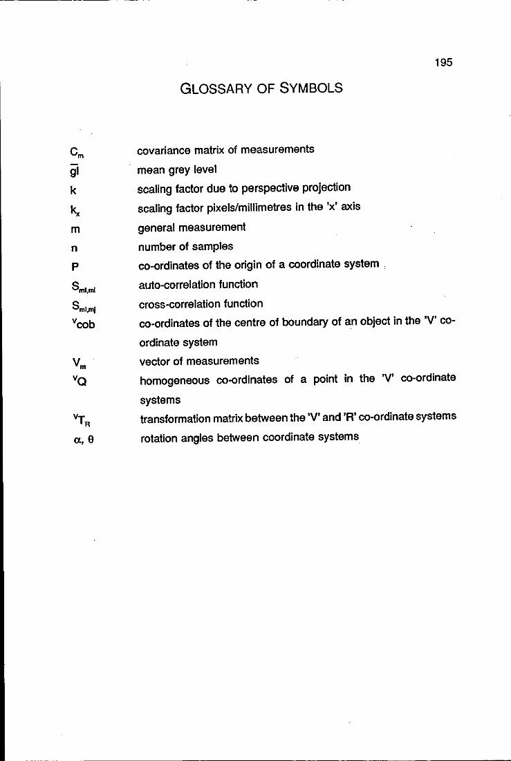
195
GLOSSARY OF SYMBOLS
Cm covariance matrix of measurements
gl mean grey level
k scaling factor due to perspective projection
k" scaling factor pixels/millimetres in the 'x' axis
m general measurement
n number of samples
p co-ordinates of the origin of a coordinate system .
Sml,mI auto-correlation function
Sml,ml cross-correlation function
vcob co-ordinates of the centre of boundary of an object in the 'V' co-
ordinate system
V m vector of measurements
vQ homogeneous co-ordinates of a point in the 'V' co-ordinate
systems
vT R transformation matrix between the 'V' and 'R' co-ordinate systems
n, e rotation angles between coordinate systems
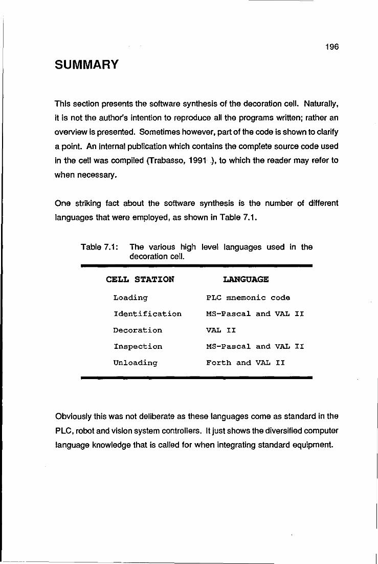
196
SUMMARY
This section presents the software synthesis of the decoration cell. Naturally,
it is not the author's intention to reproduce all the programs written; rather an
overview is presented. Sometimes however, part of the code is shown to clarify
a pOint. An internal publication which contains the complete source code used
in the cell was compiled (Trabasso, 1991 .), to which the reader may refer to
when necessary.
One striking fact about the software synthesis is the number of different
languages that were employed, as shown in Table 7.1.
Table 7.1: The various high level languages used in the decoration cell.
CELL STATION LANGUAGE
Loading PLC mnemonic code
Identification MS-Pascal and VAL 11
Decoration VAL II
Inspection MS-Pascal and VAL II
Unloading Forth and VAL 11
Obviously this was not deliberate as these languages come as standard in the
PLC, robot and vision system controllers. It just shows the diversified computer
language knowledge that is called for when integrating standard equipment.
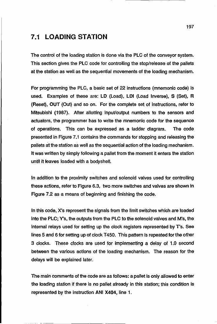
197
7.1 LOADING STATION
The control of the loading station is done via the PLC of the conveyor system.
This section gives the PLC code for controlling the stop/release of the pallets
at the station as well as the sequential movements of the loading mechanism.
For programming the PLC, a basic set of 22 instructions (mnemonic code) is
used. Examples of these are: LO (Load), LOI (Load Inverse), S (Set), R
(Reset), OUT (Out) and so on. For the complete set of instructions, refer to
Mitsubishi (1987). After allotting input/output numbers to the sensors and
actuators, the programmer has to write the mnemonic code for the sequence
of operations. This can be expressed as a ladder diagram. The code
presented in Figure 7.1 contains the commands for stopping and releasing the
pallets at the station as well as the sequential action of the loading mechanism.
It was written by simply following a pallet from the moment it enters the station
until it leaves loaded with a bodyshell.
In addition to the proximity switches and solenoid valves used for controlling
these actions, refer to Figure 6.3, two more switches and valves are shown in
Figure 7.2 as a means of beginning and finishing the code.
In this code, X's represent the Signals from the limit switches which are loaded
into the PLC; V's, the outputs from the PLC to the solenoid valves and M's, the
Internal relays used for setting up the clock registers represented by T's. See
lines 5 and 6 for setting up of clock T 450. This pattern is repeated for the other
3 clocks. These clocks are used for implementing a delay of 1.0 second
between the various actions of the loading mechanism. The reason for the
delays will be explained later.
The main comments of the code are as follows: a pallet is only allowed to enter
the loading station if there Is no pallet already in this station; this condition is
represented by the Instruction ANI X404, line 1.
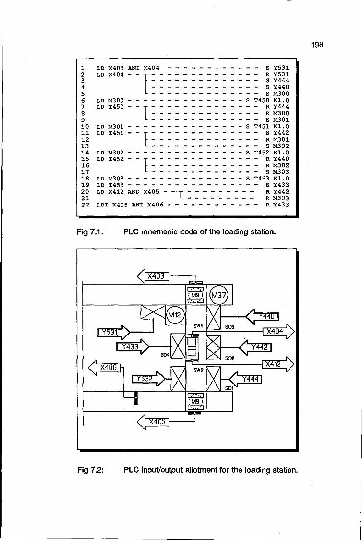
1 2 3 4 5
LD X403 ANI X404
LD X404 - - 1 ~ : --= : : ~ : : : S Y531 R Y531 S Y444 S Y440 S M300
6 LD M300 - - - - S T450 K1.0 - - - - - - - R Y444
- - - R M300 - - - - S M301
i LD T450 - - 1 = 10 LD M301 - S T451 K1.0
- - - S :.-442 - - - R M301
- - - - S M302 ~~ LD T451 - - 1 : = : ~ 14 15 16 17 18 19 20 21 22
LD M302 - - - - - - S T452 K1.0 - - - - R Y440
- - - R M302 - - - S M303
LD T452 - - 1 = = = = = : : : LD M303 - - - - - - - - - - - - S T453 K1.0 LD T453 - - - - - - - - .- - - S Y433
LD X412 AND X405 - - 1 : : : : : : : :: ~ ~~~~ LDI X405 ANI X406 - - - - - - - - - - - - R Y433
Fig 7.1: PLC mnemonic code of the loading station.
405
Fig 7.2: PLC input/output allotment for the loading station.
198

199
When the pallet gets to the loading position, the access for the next pallet to
the station is closed, line 2, and the sequential actions of the loading
mechanism are triggered: the suction cup is positioned on a bodyshell on the
chute, line 3 and then the vacuum is activated in line 4.
The next action is to return cylinder A\ to its rest position, line 7, which lifts the
bodyshell from the chute. Note that a delay was placed between these two last
actions, lines 5 and 6. This was necessary to guarantee that the instruction for
the cylinder to return to its rest position would only be processed after the
cylinder reached the bodyshell on the chute. Line 11 activates cylinder B,
attached to the crank, rotating cylinder A towards the pallet. Note again the
need for the time delay between the last two actions: rotating cylinder A at the
same time that it was returning to its rest position often resulted in bodyshell ,
dropping from the suction cup. The vacuum is deactivated in line 15 and after
a 1 second delay, the gate of the station is opened, line 19 and cylinder B
returns to its rest position, line 20. Finally the stop gate of the station is closed
again in line 22.
7.2 IDENTIFICATION STATION
This section presents the software used by the vision system and the PUMA
robot-vision system interface. This software is split into two parts: off-line and
on-line named OWLDB2 and OWL, respectively. The off-line part corresponds
to the generation of the pattern recognition and the vision-PUMA calibration
databases; these are used by the on-line software for identifying the body shells
and managing the vision-robot interface.
1 Cylinders A and B of the loading mechanism are shown in Figure 5.1.
2 OWLDB Is short for OWLDataBase. The three main programs of the decoration cell are OWl, EAGLE and PUFFiN, which respectively control the vision system, the PUMA robot and the RTX robot.
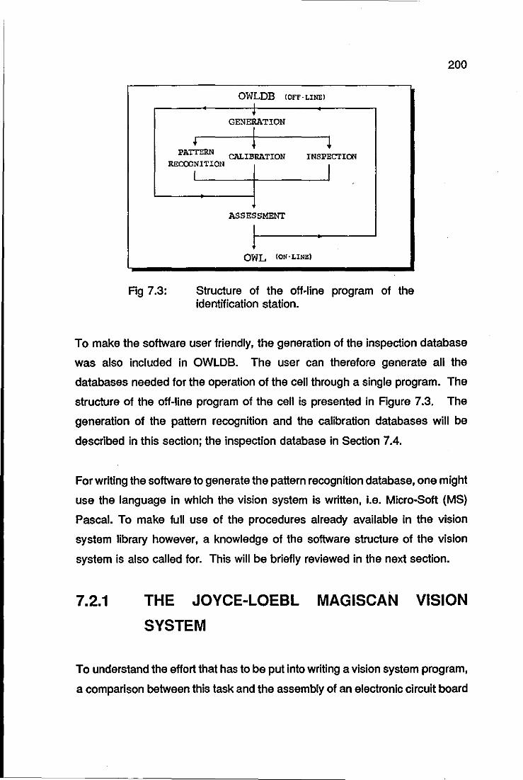
Fig 7.3:
OWLDB (OFF-LINEI I ~
GENERATION
1 1 PATTERN CALIBRATION
RECOONITIQN INSPECTION
I I
ASSESSMENT
I J
OWL (ON-LINE)
Structure of the off-line program of the identification station.
200
To make the software user friendly, the generation of the inspection database
was also included in OWLDB. The user can therefore generate all the
databases needed for the operation of the cell through a single program. The
structure of the off-line program of the cell is presented in Figure 7.3. The
generation of the pattern recognition and the calibration databases will be
described in this section; the inspection database in Section 7.4.
For writing the software to generate the pattern recognition database, one might
use the language in which the vision system is written, i.e. Micro-Soft (MS)
Pascal. To make full use of the procedures already available in the vision
system library however, a knowledge of the software structure of the vision
system is also called for. This will be briefly reviewed in the next section.
7.2.1 THE JOYCE-LOEBL MAGISCAN VISION
SYSTEM
To understand the effort that has to be put into writing a vision system program,
a comparison between this task and the assembly of an electronic circuit board
201
seems to be a good parallel.
After defining the functional requirements of a circuit, the designer starts putting
together the various components in order to achieve the desired result. The
vast majority of the electronic components needed are available off-the-shelf,
such as diodes, transistors, resistors, etc. Sometimes the designer has to resort
to designing specific components, although nowadays this is becoming very
rare.
The MAGISCAN vision system can be thought of as a shelf from which the
'components' necessary for 'assembly' of a program can be taken. Keeping the
comparison, the routine that inputs the contents of an image into the vision
system can be thought of as a resistor; the routine that calculates the centre
of the area of an object as a diode, and so forth. It is left to the programmer to
'assemble' these 'components' in a proper manner in order to achieve the
desired result.
As various electronic components can be placed in a single chip, one will find
in MAGISCAN a number of routines placed in units. For instance, the unit
MXRT contains routines to execute operations with images such as addition,
subtraction, edge enhancement and so on; the unit MXTVPES contains all
types3 used in MAGISCAN, starting with a simple constant, e.g. number 7t up
to very complex records composed of a number of fields. All units can be
compiled separately from the user's program. For a complete description of the
MAGISCAN units, refer to Joyce-Loebl (1987).
For accessing the routines of these units, the programmer has to declare them
in the header of his program and subsequently link the object code of the
program to the object code of the units. This is done using the DOS linker.
3 Pascal structure.
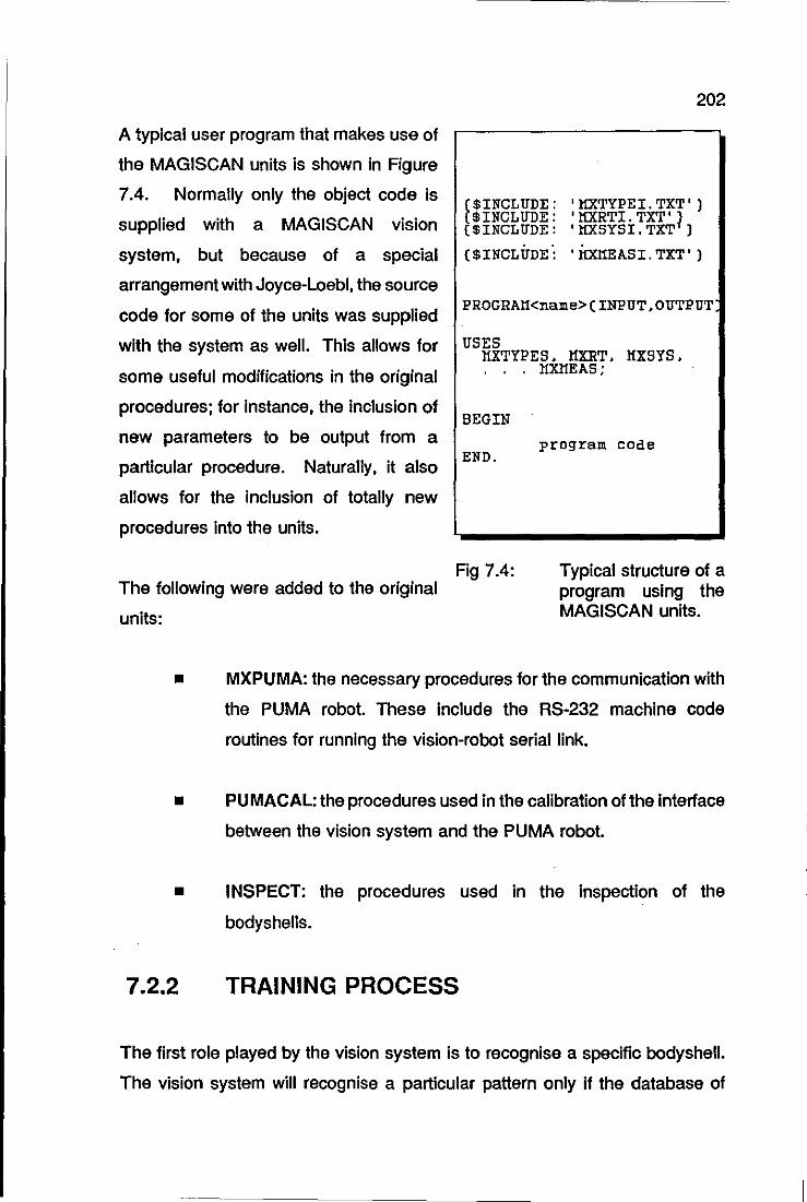
A typical user program that makes use of
the MAGISCAN units is shown in Figure
7.4. Normally only the object code is
supplied with a MAGISCAN vision
system, but because of a special
arrangement with Joyce-Loebl, the source
code for some of the units was supplied
with the system as well. This allows for
some useful modifications in the original
procedures; for instance, the inclusion of
new parameters to be output from a
particular procedure. Naturally, it also
allows for the inclusion of totally new
procedures into the units.
($INCLUDE ($INCLUDE ($INCLUDE
202
, lfXTYPEI. TXT' ) , lfXRTI. TXT' 1 'lfXSYSI. TXT )
($INCLUDE: 'lfXHEASI.TXT')
PROGRAH<name>(INPUT.OUTPUT
USES HXTYPES. HXRT. HXSYS .
. l1XHEAS;
BEGIN
END. program code
Fig 7.4: Typical structure of a program using the MAGISCAN units.
The following were added to the original
units:
• MXPUMA: the necessary procedures for the communication with
the PUMA robot. These include the RS-232 machine code
routines for running the vision-robot serial link.
• PUMACAL: the procedures used in the calibration of the interface
between the vision system and the PUMA robot.
• INSPECT: the procedures used in the inspection of the
bodyshells.
7.2.2 TRAINING PROCESS
The first role played by the vision system is to recognise a specific bodyshell.
The vision system will recognise a particular pattern only if the database of
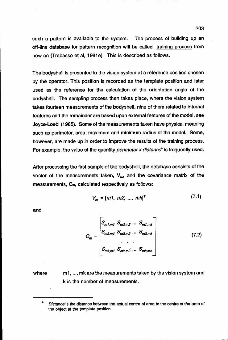
203
such a pattern is available to the system. The process of building up an
off-line database for pattern recognition will be called training process from
now on (Trabasso et ai, 1991e). This is described as follows.
The bodyshell is presented to the vision system at a reference position chosen
by the operator. This position is recorded as the template position and later
used as the reference for the calculation of the orientation angle of the
bodyshell. The sampling process then takes place, where the vision system
takes fourteen measurements of the bodyshell, nine of them related to internal
features and the remainder are based upon external features of the model, see
Joyce-Loebl (1985). Some of the measurements taken have physical meaning
such as perimeter, area, maximum and minimum radius of the model: Some,
however, are made up in order to improve the results of the training process.
For example, the value of the quantity perimeter x distance4 is frequently used.
After processing the first sample of the bodyshell, the database consists of the
vector of the measurements taken, Vm, and the covariance matrix of the
measurements, Cm, calculated respectively as follows:
and
Vm = Imf, m2, ... , mW (7.1)
c = m
Smt.mt Sm2.m2 ••• Smt,mk
Sm2,ml Sm2,m2 ... Sm2,mk (7.2)
where m1, ... , mk are the measurements taken by the vision system and
k is the number of measurements.
4 Distance Is the distance between the actual centre of area to the centre of the area of the Object at the template posnlon.
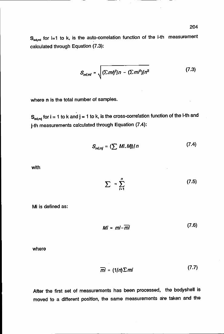
204
Sm~ml for i= 1 to k, is the auto-correlation function of the i-th measurement
calculated through Equation (7.3):
where n is the total number of samples.
Sml,ml for i = 1 to k and j = 1 to k, is the cross-correlation function of the I-th and
I-th measurements calculated through Equation (7.4):
SmI.m/ = (L Mi. MM n (7.4)
with
n
L=L (7.5)
1-1
Mi is defined as:
Mi = mi-mi (7.6)
where
mi = (1/n)'Emi (7.7)
After the first set of measurements has been processed, the bodyshell is
moved to a different position, the same measurements are taken and the
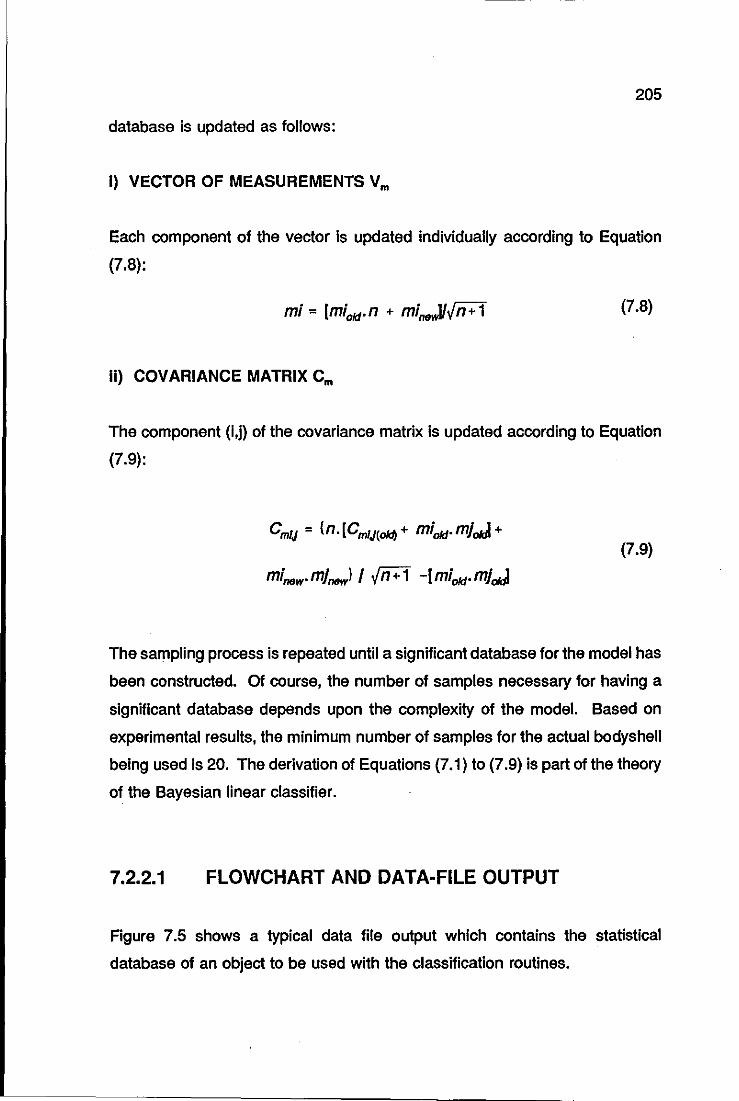
205
database is updated as follows:
I) VECTOR OF MEASUREMENTS Vm
Each component of the vector is updated individually according to Equation
(7.8):
(7.8)
Ii) COVARIANCE MATRIX Cm
The component (I,n of the covariance matrix is updated according to Equation
(7.9):
(7.9)
The sampling process is repeated until a significant database for the model has
been constructed. Of course, the number of samples necessary for having a
significant database depends upon the complexity of the model. Based on
experimental results, the minimum number of samples for the actual bodyshell
being used is 20. The derivation of Equations (7.1) to (7.9) is part of the theory
of the Bayesian linear classifier.
7.2.2.1 FLOWCHART AND DATA·FILE OUTPUT
Figure 7.5 shows a typical data file output which contains the statistical
database of an object to be used with the classification routines.
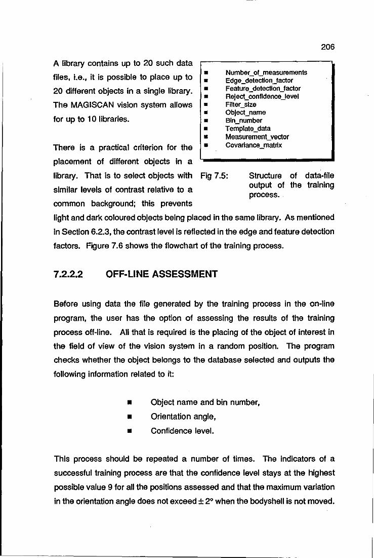
A library contains up to 20 such data
files, i.e., it is possible to place up to
20 different objects in a single library.
The MAGISCAN vision system allows
for up to 10 libraries.
There is a practical criterion for the
placement of different objects in a
• • • • • • • • • •
NumbecoCmeasurements Edge _detection_factor Feature _detection_factor Reject30nfldence_level Filter_size Object_name Bin_number Template_data Measurement_vector Covarlance_matrlx
206
library. That is to select objects with Fig 7.5: Structure of data-file output of the training process.
similar levels of contrast relative to a
common background; this prevents
light and dark coloured objects being placed in the same library. As mentioned
in Section 6.2.3, the contrast level is reflected in the edge and feature detection
factors. Figure 7.6 shows the flowchart of the training process.
7.2.2.2 OFF-LINE ASSESSMENT
Before using data the file generated by the training process in the on-line
program, the user has the option of asseSSing the results of the training
process off-line. All that is required is the placing of the object of interest in
the field of view of the vision system in a random position. The program
checks whether the object belongs to the database selected and outputs the
following information related to it:
• Object name and bin number,
• Orientation angle,
• Confidence level.
This process should be repeated a number of times. The indicators of a
successful training process are that the confidence level stays at the highest
possible value 9 for all the positions assessed and that the maximum variation
in the orientation angle does not exceed ± 2° when the bodyshell is not moved.
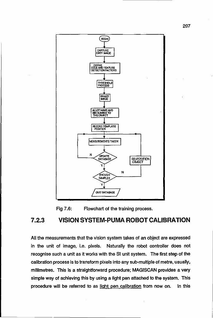
7.2.3
Fig 7.6:
OEFINE EOOE AND FEAn.mE OETECTD4 FACTORS
N
Flowchart of the training process.
207
VISION SYSTEM-PUMA ROBOT CALIBRATION
All the measurements that the vision system takes of an object are expressed
in the unit of image, i.e. pixels. Naturally the robot controller does not
recognise such a unit as it works with the SI unit system. The first step of the
calibration process is to transform pixels into any sub-multiple of metre, usually,
millimetres. This is a straightforward procedure; MAGISCAN provides a very
simple way of achieving this by using a light pen attached to the system. This
procedure will be referred to as light pen calibration from now on. In this
208
procedure the user is required to place in the camera field of view an object of
known length, a ruler, for example, and input to the vision system the length of
the object in the units which the pixels are to be calibrated against. Then the
user draws a line over the object on the screen of the vision system using the
light pen. The vision system then calculates the number of pixels
corresponding to that length and outputs the calibration factor expressed in
pixels/millimetres, for instance.
If a tube camera is used, then the light pen calibration needs to be executed
once, with the object positioned either horizontally or vertically relative to the
screen of the vision system. This is because the pixels in a tube camera are
square shaped. However, for a CCO camera which has rectangular shaped
pixels, the light pen calibration has to be executed twice, for the horizontal and
vertical directions as the calibration factors are different in each direction.
The second step in the calibration of the vision system-robot interface is the
establishment of the spatial relationship between the two co-ordinate systems.
Suppose that the vision system has calculated the co-ordinates of the centre
of the boundary of a bodyshell initially in pixels; then, these are transformed
into millimetres using the calibration factors previously obtained. Let Ycob. and
YCOby be these co-ordinates. To allow the robot to position the gripper at the
centre of the boundary of the bodyshell, the co-ordinates Rcob. and RCOby have
to be calculated. These are the previous variables, now expressed in the robot
coordinate system. Suppose the situations shown in Figure 7.7. The
relationship between the two sets of variables is simply:
(7.10) Rcob = -cosa vcob -sina vc;ob + p y x y y
5 The z co-ordinate was omitted because the depth information can not be obtained by the vision system used in the cell.
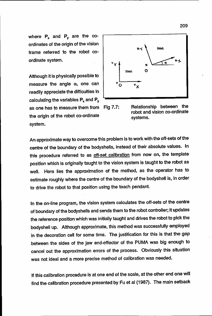
where p. and P y are the co
ordinates of the origin of the vision
frame referred to the robot co
ordinate system.
Although it is physically possible to
measure the angle 0;, one can
readily appreciate the difficulties in
calculating the variables p. and Py
as one has to measure them from Fig 7.7:
the origin of the robot co-ordinate
system.
209
Relationship between the robot and vision co-ordinate systems.
An approximate way to overcome this problem is to work with the ott-sets of the
centre of the boundary of the bodyshells, instead of their absolute values. In
this procedure referred to as off-set calibration from now on, the template
position which is originally taught to the vision system is taught to the robot as
well. Here lies the approximation of the method, as the operator has to
estimate roughly where the centre of the boundary of the bodyshell is, in order
to drive the robot to that position using the teach pendant.
In the on-line program, the vision system calculates the off-sets of the centre
of boundary of the bodyshells and sends them to the robot controller; it updates
the reference position which was initially taught and drives the robot to pick the
bodyshell up. Although approximate, this method was successfully employed
in the decoration cell for some time. The justification for this is that the gap
between the sides of the jaw end-effector of the PUMA was big enough to
cancel out the approximation errors of the process. Obviously this situation
was not ideal and a more precise method of calibration was needed.
If this calibration procedure is at one end of the scale, at the other end one will
find the calibration procedure presented by Fu et al (1987). The main setback

210
of this method is not the solution of the linear system of equations with 12
unknown coefficients, as there are a number of numerical techniques available
to achieve this. It is rather the work-load put on the operator who is carrying
out the calibration procedures as well the complexity of the jig required for the
calibration. He is required to teach the robot at least 6 different points and to
input the image of these points to the vision system.
It was felt the an alternative method of calibration was needed, positioned in
between these two procedures just described. A semi-automatic method was
derived in an original manner (Trabasso and Zielinski, 1991), which puts a very
small work-load on the operator; it requires a simple calibration apparatus and
the solution of a very simple system of equations. It has been successfully
used in the decoration cell since it was derived; it will be referred to as the
probe calibration method as the robot uses a probe like end-effector for
recording the necessary pOints to be used in the method.
7.2.4 THE PROBE CALIBRATION APPROACH
This sections briefly reviews the two main aspects of the approach i.e., the
theoretical development and the necessary hardware for its implementation.
7.2.4.1 THEORETICAL DEVELOPMENT
Figure 7.8 shows the relative positions of the robot and vision co-ordinate
frames. To calibrate the vision-robot interface, one has to calculate the
transform matrix IT R between the image plane and the robot coordinate system:
(7.11 )
where: IQ is the column vector representing the homogeneous co-
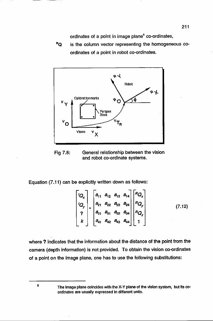
211
ordinates of a point in image plane6 co-ordinates,
RQ is the column vector representing the homogeneous co
ordinates of a point in robot co-ordinates.
Fig 7.8:
Cahbratbn mari:s ~
n Perspex 0 U\BIOCk
VisIOn
Robot
General relationship between the vision and robot co-ordinate systems.
Equation (7.11) can be explicitly written down as follows:
IQ 8 11 8 12 8 13 8 14 RQ
x x
IQ 8:21 Bz2 y = 8:23 8:24 RQ
y (7.12)
? Sal Sa1 Sa2 8a.t RQ z
k 841 842 843 B.s4 1
where? indicates that the information about the distance of the point from the
camera (depth information) is not provided. To obtain the vision co-ordinates
of a point on the image plane, one has to use the following substitutions:
6 The Image plane coincides with the X-Y plane of the vision system, but Its coordinates are usually expressed In different units.
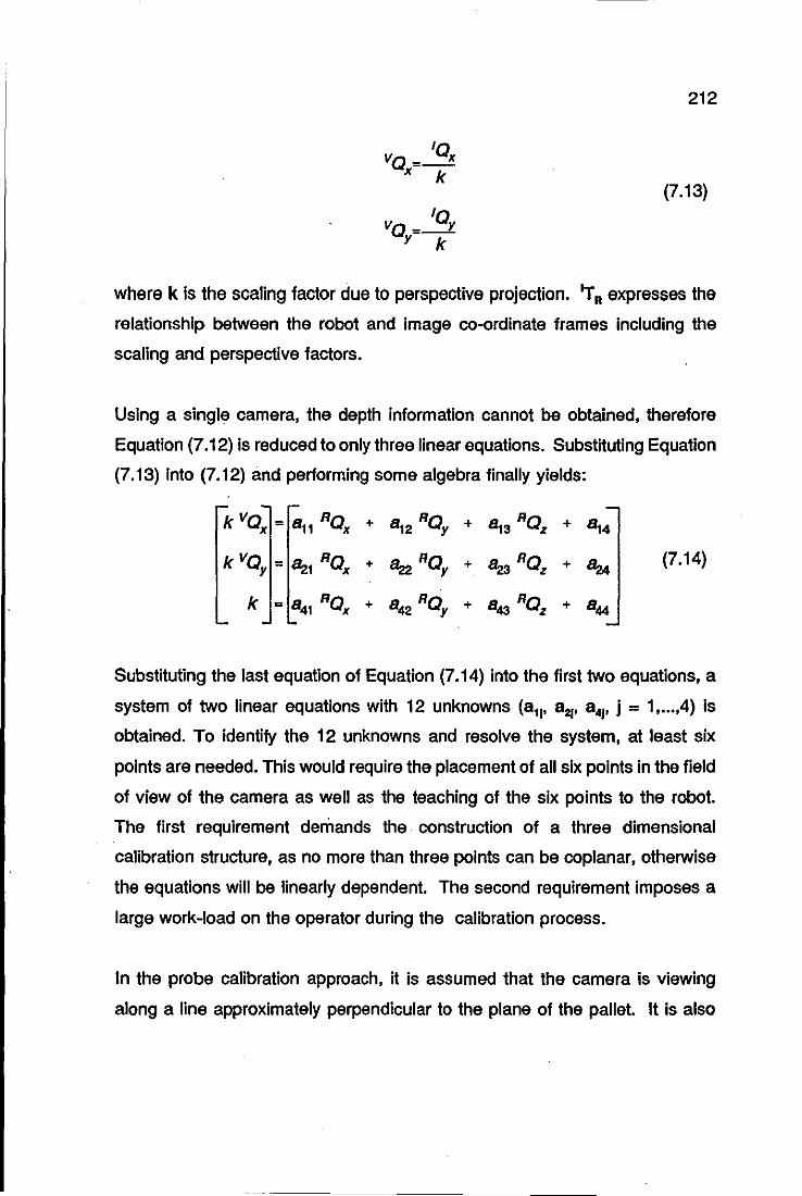
VQ = IQx x k
VQ = IQy y k
212
(7.13)
where k is the scaling factor due to perspective projection. .,. R expresses the
relationship between the robot and image co-ordinate frames including the
scaling and perspective factors.
Using a single camera, the depth information cannot be obtained, therefore
Equation (7.12) is reduced to only three linear equations. Substituting Equation
(7.13) into (7.12) and performing some algebra finally yields:
k vQy = ~1 RQx + ~ RQy + ~ RQz + Bz4
k = 841 RQx + 842 RQy + 843 RQz + 844
(7.14)
Substituting the last equation of Equation (7.14) into the first two equations, a
system of two linear equations with 12 unknowns (a11, a21, 8 41, j = 1, ... .4) is
obtained. To identify the 12 unknowns and resolve the system, at least six
pOints are needed. This would require the placement of all six points in the field
of view of the camera as well as the teaching of the six points to the robot.
The first requirement demands the construction of a three dimensional
calibration structure, as no more than three points can be coplanar, otherwise
the equations will be linearly dependent. The second requirement imposes a
large work-load on the operator during the calibration process.
In the probe calibration approach, it is assumed that the camera is viewing
along a line approximately perpendicular to the plane of the pallet. It is also
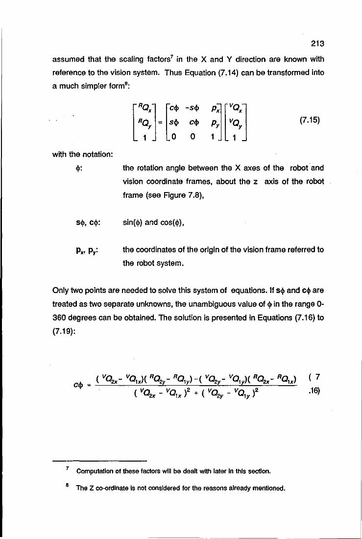
213
assumed that the scaling factors7 in the X and Y direction are known with
reference to the vision system. Thus Equation (7.14) can be transformed into
a much simpler forms:
-sel>
eel>
o (7.15)
with the notation:
<\I: the rotation angle between the X axes of the robot' and
vision coordinate frames, about the z axis of the robot
frame (see Figure 7.8),
sin (<\I) and cos(<\I),
the coordinates of the origin of the vision frame referred to
the robot system.
Only two points are needed to solve this system of equations. If s<\I and c<\l are
treated as two separate unknowns, the unambiguous value of <\I in the range 0-
360 degrees can be obtained. The solution is presented in Equations (7.16) to
(7.19):
eel> = ( VQ2x- vQ1X)( RQ2Y- RQ1Y) -( VQ2Y- VQ1Y)( RQ2x- RQ1X>
( vqx - VQ1X)2 + ( vqy _ VQly)2
7 Computation of these factors will be dealt with later In this section.
S The Z co-ordinate Is not considered for the reasons already mentioned.
( 7
.16)
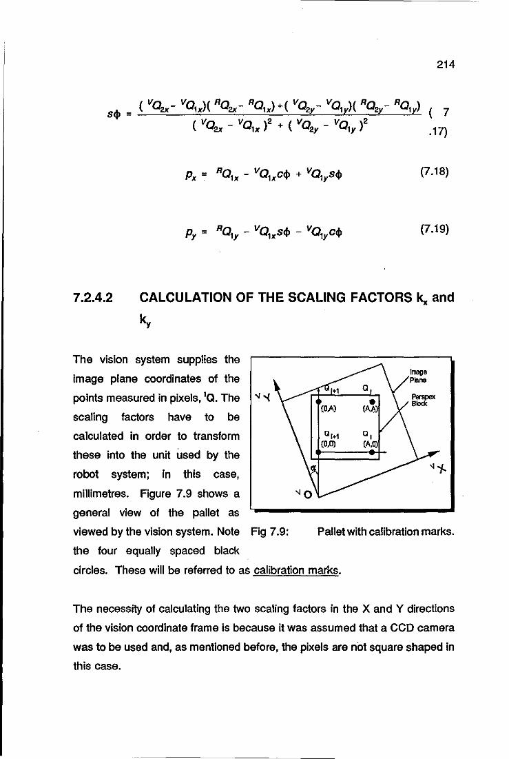
sell =
214
( 7
.17)
(7.18)
(7.19)
7.2.4.2 CALCULATION OF THE SCALING FACTORS k,. and
ky
The vision system supplies the
image plane coordinates of the
pOints measured in pixels, IQ. The -.j -{
scaling factors have to be
calculated in order to transform
these into the unit used by the
robot system; in this case,
millimetres. Figure 7.9 shows a
general view of the pallet as
viewed by the vision system. Note Fig 7.9:
the four equally spaced black
Pallet with calibration marks.
circles. These will be referred to as calibration marks.
The necessity of calculating the two scaling factors in the X and Y directions
of the vision coordinate frame is because it was assumed that a CCO camera
was to be used and, as mentioned before, the pixels are not square shaped in
this case.
215
written as:
(7.20)
with vQ originally given in pixels as IQ; it is transformed into millimetres by:
kx 'Ox
Vo = kylOy (7.21 )
?
1
Substituting Equation (7.21) into (7.20) and stating the result in terms of the
individual components, results in:
k '0 = Po Ca - Po Sa + Px x x x y (7.22)
Since the values of the translation components p. and Py can be disregarded
for this calculation, the difference between the coordinates of two points QI and
QJ can be used to rewriting Equation (7.22) as follows:
kx (,Olx - 'Ojx) = (POIx - POjx) Ca -(POly - POlY) Sa
ky('OIy- 'OIY} = (POIx - POjx}sa +:(POIy- POIY}ca
(7.23)
If one considers ca and sa9 as two separate unknown variables, then a set of
four equations is needed for the calculation of all the variables. The required
set of equations is obtained by substituting i=1 and i=2 in Equation (7.23),
yielding:
9 ca = eos(a) and sa = sin(a)
kX(IQ1X- IQjx) = (PQ1X- PQjx)ca; - (PQ1Y- PQjy)sa;
ky ('Q1Y - IOw) = (PQ1X - Pq..) sa; + (PQ1Y - POw) ca;
kx ('Q2x - IQjx) = (PQ2x - PQjx) ca - (PQ2Y - PQjy) sa;
k y (,Q2Y- IQjy) = (PQ2x- PQjx)sa; + (PQ2Y- PQjy)ca;
216
(7.24)
Obviously the points QI' Q 1 and Q 2 should not be collinear. The distances
between these points are A, see Figure 7.9. It can be also observed from this
figure that some of the terms in Equations (7.24) are zero. Making these
slmplifications, k,. and ky can finally be calculated as:
k - A x J( 'Q1X _ IQjx)2 + ( IQ2x _ IQjx)2
(7.25)
k A y J( IQ _ IQ)2 + ('Q _ IQ )2
ly IY 2y IY
These scaling factors are used to convert pixels into millimetres, taking into
account any possible misalignment between the X-V axes of the image and
pallet coordinate frames.
7.2.4.3 COMPLEMENTARY STEPS FOR DEFINING A ROBOT
LOCATION
What has been described so far allows the X-V coordinates of a point in the
field of view of the vision system to be converted into robot coordinates.
However, a robot location is fully defined by six components:
(7.26)
with:
Any location in the workspace of the robot,
Cartesian coordinates of the location,
217
x, y, z:
0, a', t: Orientation angles of the robot tool at this location.
The orientation angles can be set according to the way one wishes the robot
to grasp the target object and therefore they are not considered as part of the
calibration procedure. Even though the z Cartesian coordinate cannot be
supplied by the vision system it has to be computed. It is essentially the height
of the object at the grasping poSition, measured from the pallet. The equation
of the plane10 containing the pallet can be calculated by using three taught
pOints on the pallet plane. Let the coordinates of these three pOints be:
(7.27)
for i = 1, 2, 3.
The equation of the plane is:
x - RQ1X Y - RQ1Y Z - RQ1Z
det RQ2x- RQ1X RQ2Y- RQ1Y RQ2z- RQ1Z = 0 (7.28)
RQ3X- RQ1X RQ3Y- RQ1Y RQ3Z _ RHx,.
Knowing the image plane coordinates of any point, the respective robot x and
y coordinates of this point can be found by using Equations (7.15) and (7.22).
As the plane of the pallet is approximately parallel to the X-Y plane of the robot
coordinate frame, one substitutes x=RQx, y=RQy and z=z-H in Equation (7.28)
to obtain the z coordinate H millimetres above the pallet.
lOin relation to the robot co-ordinate frame.
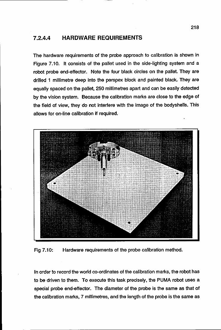
218
7.2.4.4 HARDWARE REQUIREMENTS
The hardware requirements of the probe approach to calibration is shown in
Figure 7.10. It consists of the pallet used in the side-lighting system and a
robot probe end-effector. Note the four black circles on the pallet. They are
drilled 1 millimetre deep into the perspex block and painted black. They are
equally spaced on the pallet, 250 millimetres apart and can be easily detected
by the vision system. Because the calibration marks are close to the edge of
the field of view, they do not interfere with the image of the bodyshells. This
allows for on-line calibration if required.
Fig 7.10: Hardware requirements of the probe calibration method.
In order to record the world co-ordinates of the calibration marks, the robot has
to be driven to them. To execute this task precisely, the PUMA robot uses a
special probe end-effector. The diameter of the probe is the same as that of
the calibration marks, 7 millimetres, and the length of the probe is the same as
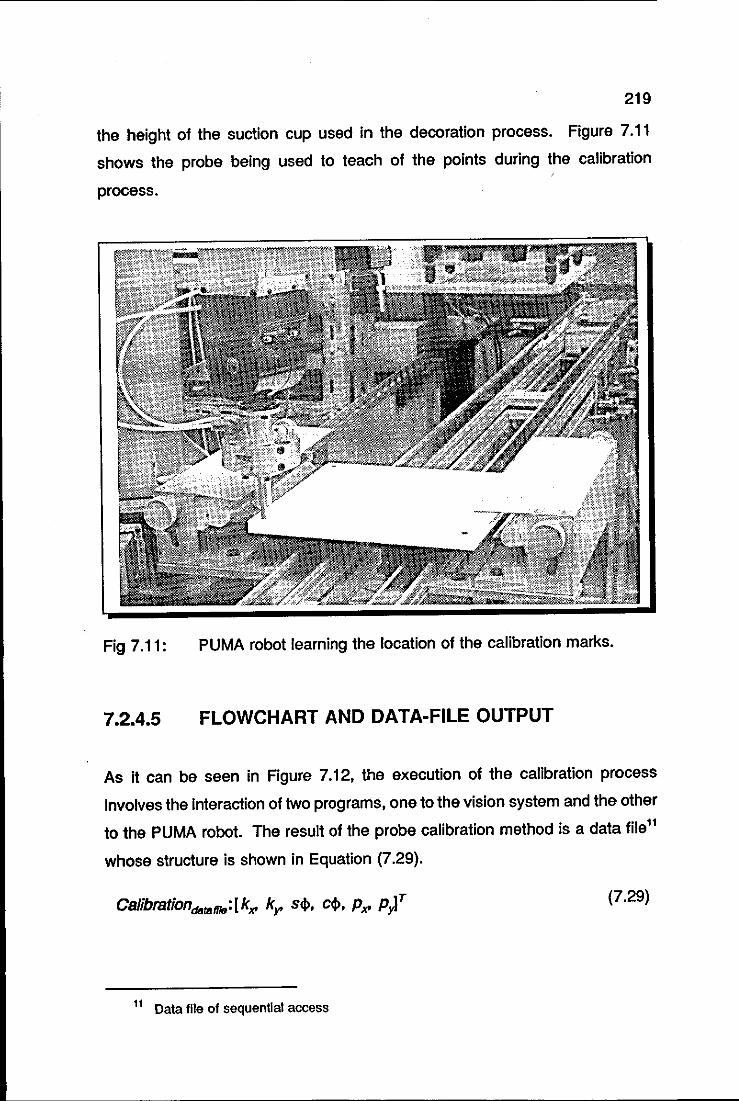
219
the height of the suction cup used in the decoration process. Figure 7.11
shows the probe being used to teach of the pOints during the calibration
process.
Fig 7.11: PUMA robot learning the location of the calibration marks.
7.2.4.5 FLOWCHART AND DATA-FILE OUTPUT
As it can be seen in Figure 7.12, the execution of the calibration process
involves the interaction of two programs, one to the vision system and the other
to the PUMA robot. The result of the probe calibration method is a data filell
whose structure is shown in Equation (7.29).
(7.29)
11 Data file of sequential access
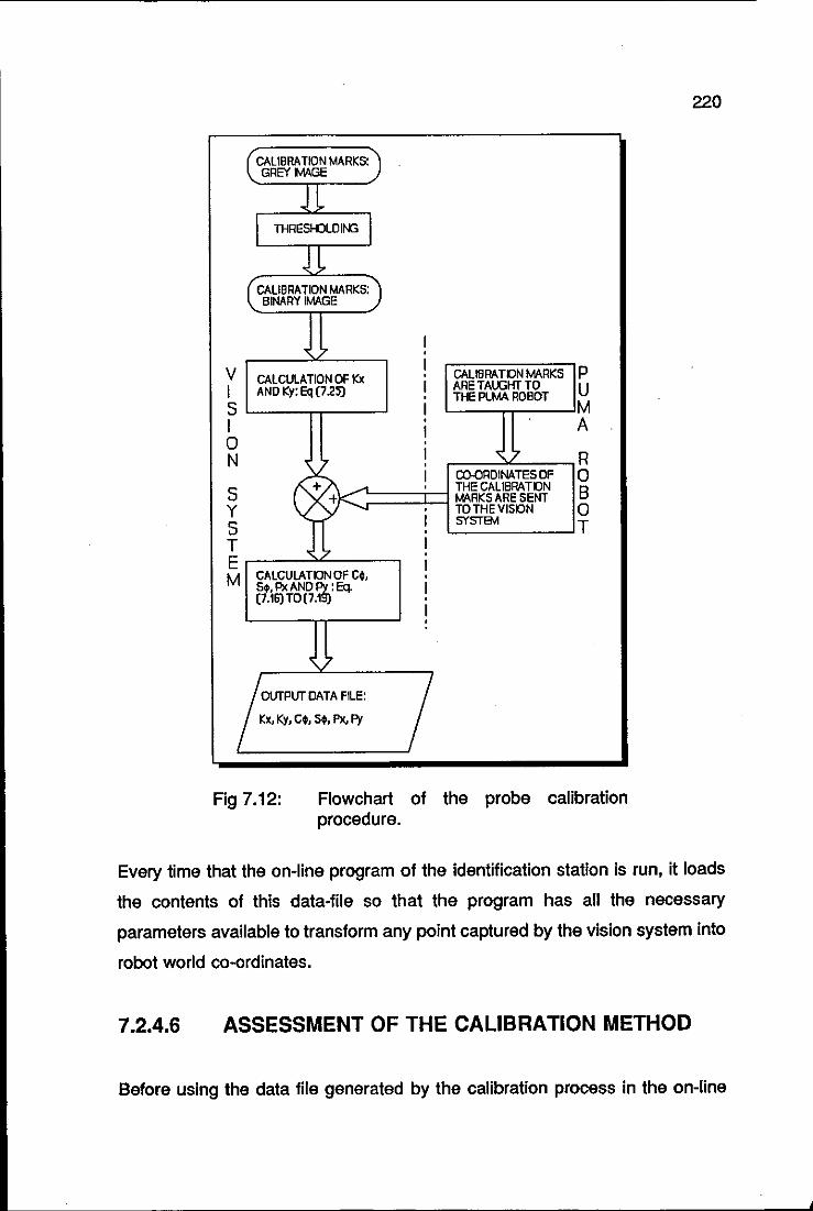
(CALIBRATION MARKS:) GREYMAGE
1 I THRESHJLOII'G I
1 CALIBRATION MARKS: BINARY IMAGE
, 7
V CALCULATION OF Kx CALlBRATON MARKS P I AND Ky: Eq (725) ARETAlXiHT TO U S
THE PUMA ROBOT M
I A 0
, 7 N , 7 R
CO-ORDINATES OF 0 S + ..... THE CALl8RATON B + MARKS ARE SENT Y .... · TOTHEVISON 0 S
,..., I SYSTe.1 T · T , ~ I E · I M CALCULATONoF C~. •
St. Px AND ~i Eq. I (7.16)TO(7.1 · I ·
~
!~~"'U" Kx, Ky, C~, St. Px, Py / Fig 7.12: Flowchart of the probe calibration
procedure.
220
Every time that the on-line program of the identification station is run, it loads
the contents of this data-file so that the program has all the necessary
parameters available to transform any point captured by the vision system into
robot world co-ordinates.
7.2.4.6 ASSESSMENT OF THE CALIBRATION METHOD
Before using the data file generated by the calibration process in the on-line
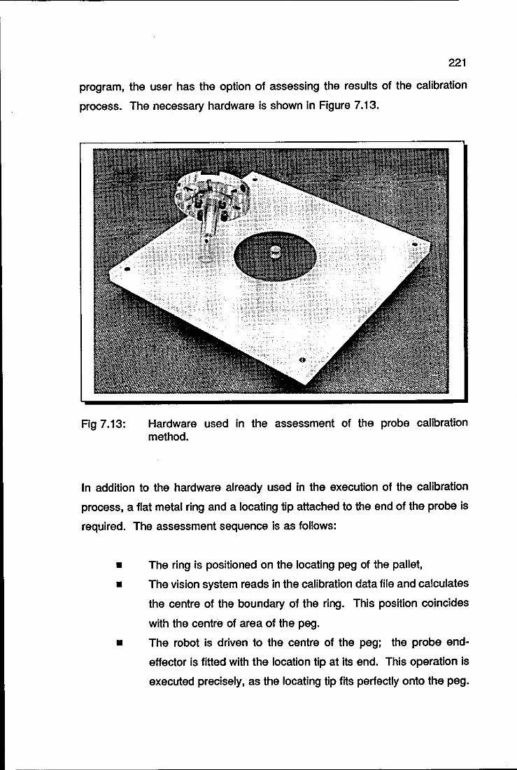
221
program, the user has the option of assessing the results of the calibration
process. The necessary hardware is shown in Figure 7.13.
Fig 7.13: Hardware used in the assessment of the probe calibration method.
In addition to the hardware already used in the execution of the calibration
process, a flat metal ring and a locating tip attached to the end of the probe is
required. The assessment sequence is as follows:
• The ring is positioned on the locating peg of the pallet,
• The vision system reads in the calibration data file and calculates
the centre of the boundary of the ring. This position coincides
with the centre of area of the peg.
• The robot is driven to the centre of the peg; the probe end
effector is fitted with the location tip at its end. This operation is
executed precisely, as the locating tip fits perfectly onto the peg.
--~~~----------------------------------
7.2.5
222
The robot world co-ordinates of the centre of the peg are then
sent to the vision system.
• The vision system has now all the necessary elements for
checking Equation (7.15). Naturally, one expects to find some
divergence between the location sent by the robot and that
calculated by the vision system. This is due to quantification
errors of the camera and non-linearities of the vision system.
This divergence however, should not exceed ± 1 millimetre12 for
both X and V co-ordinates.
THE ON-LINE PROGRAM - OWL
That which has been described so far corresponds to the off-line program of
the station, OWLDB. The data generated by this program, namely, the pattern
recognition database and the calibration database is used by the on-line
program of the station in order to:
• identify the bodyshell on the pallet,
• drive the PUMA robot to pick the bodyshell from the pallet.
To identify a bodyshell, the vision system again takes a set of measurements
of the bodyshell and compares it with the database, and based upon the
distance of the actual set from the database, the system will either accept the
model or reject it. The mathematical model for the identification or rather
classification process is the classical Bayesian classifier summarised below.
The Bayesian linear discriminant classifier is of the form of a minimum distance
classifier for single prototypes, where the prototype of each class is its mean
12 This maximum deviation was arrived at after executing the probe calibration method
and the associated assessment procedure a considerable number of times.
223
feature (measurement) vector, as defined in Equation (7.1).
unknown prototype, X, the distance dl(X) is calculated as follows:
Given an
(7.30)
where: Mi is the mean feature vector of class wl and
C is the pooled covariance matrix for all classes.
X is a member of class wi if
d~X) > dj(X) for all i'l'j (7.31)
Naturally, there is a tolerance to be set in the classification process, i.e. how
close to the database a set of measurements of a bodyshell has to be in order
to have the bodyshell accepted as a member of the database. This tolerance
is defined as the confidence level of the process and is set by the user. The
minimum and maximum confidence levels in the MAGISCAN system are 0 and
9, respectively. For further details of the classification process described
above, see Joyce-Loebl [7.4]. After successfully identifying a bodyshell, the
vision system sends the following information related to the bodyshell to the
PUMA robot:
• Bin number, which identifies uniquely each model in each library,
• x and y co-ordinates of the centre of boundary of the bodyshell,
already transformed into robot world co-ordinates by the use of
the calibration database.
• Orientation angle, which is measured between the actual
orientation of the bodyshell and that of its template position.
With this information, the PUMA robot program EAGLE the location of the
centre of the boundary of the bodyshell as follows:
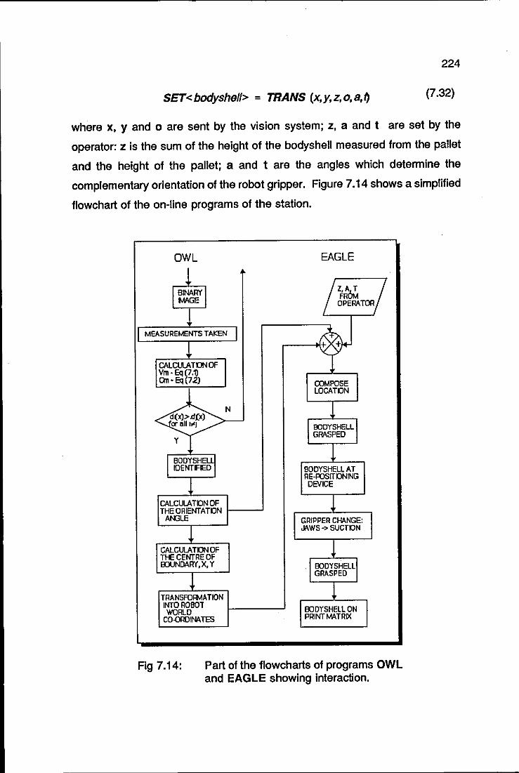
224
SET<bodyshel/> = TRANS (x,y,z,o,a,t) (7.32)
where x, y and 0 are sent by the vision system; z, a and t are set by the
operator: Z is the sum of the height of the bodyshell measured from the pallet
and the height of the pallet; a and t are the angles which determine the
complementary orientation of the robot gripper. Figure 7.14 shows a simplified
flowchart of the on-line programs of the station.
OWL EAGLE
1 I~WI /Z,A,T RI FROM
OPERATOR
1 r MEASUREMENTS TAKEN I t ~ CALCUlA TON OF Vm· Eq \7.1) O'n-Eq 72) COMPOSE
LOCATON
N T d(x».d£x) or an "J BODYSHELL
Y GRASPEO
1 I BODY5HEL~1 IOENTIFIED BOOYSHELL AT
~ RE-POsrrONING DEVICE
CALCULA TON OF 1 THE ORIENTATON At-I3LE GRIPPER CHANGE:
~ JAWS -> SUCTON
CALCUlA TON OF 1 THE CENTRE OF EOUNDARY, X, Y EODYSHELL
! GRASPED
1 TRANSFORMATION INTO ROBOT EODYSHELL ON WORLD CO.QRDINA TES PRINT MATRIX
Fig 7.14: Part of the flowcharts of programs OWL and EAGLE showing interaction.
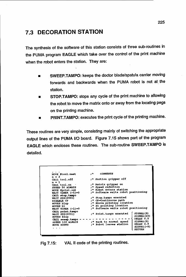
225
7.3 DECORATION STATION
The synthesis of the software of this station consists of three sub-routines in
the PUMA program EAGLE which take over the control of the print machine
when the robot enters the station. They are:
• SWEEP.TAMPO: keeps the doctor blade/spatula carrier moving
forwards and backwards when the PUMA robot is not at the
station.
• STOP.TAMPO: stops any cycle of the print machine to allowing
the robot to move the matrix onto or away from the locating pegs
on the printing machine.
• PRINT.TAMPO: executes the print cycle of the printing machine.
These routines are very Simple, consisting mainly of switching the appropriate
output lines of the PUMA I/O board. Figure 7.15 shows part of the program
EAGLE which encloses these routines. The sub-routine SWEEP.TAMPO is
detailed.
MOVE ,tool.nest n - 3 CALL tool.off n - 1
;* COMMENTS
;* suction gripper off
;* Matrix gripper on ;* Speed reduction ;* Robot enters station ;* software wait. robot posltlonlnq
CALL tool. on . SPEED 50 ALWAYS MOVE 'print.out WAIT TXMER (-1,-0 CALL atop.tampo WAIT SIG(2001) ;* Stop.tampo executed DISABLE CP ;.,. cp-continuOU8 path MOVES blup ;* Above printing location HOVES hi ;* At printing location W1IT TIMER (-1)-0 ;* Software waits robot positioning CALL print. tempo WAIT SIG(2001) ;* Print.tampo executed I SIGNAL(9) HOVES blup SIGNAL (10) CALL a.eep.tampo _ - - - - - - - - - - - - - - - DELAY 0.5 SPEED 100 ALWAYS ;* Back to normal speed SIGNAL(S) MOVE ROUND ;* Robot leaves station DELAY 0.5 • • • SIGNAL (-8)
RETURN
Fig 7.15: VAL 11 code of the printing routines.
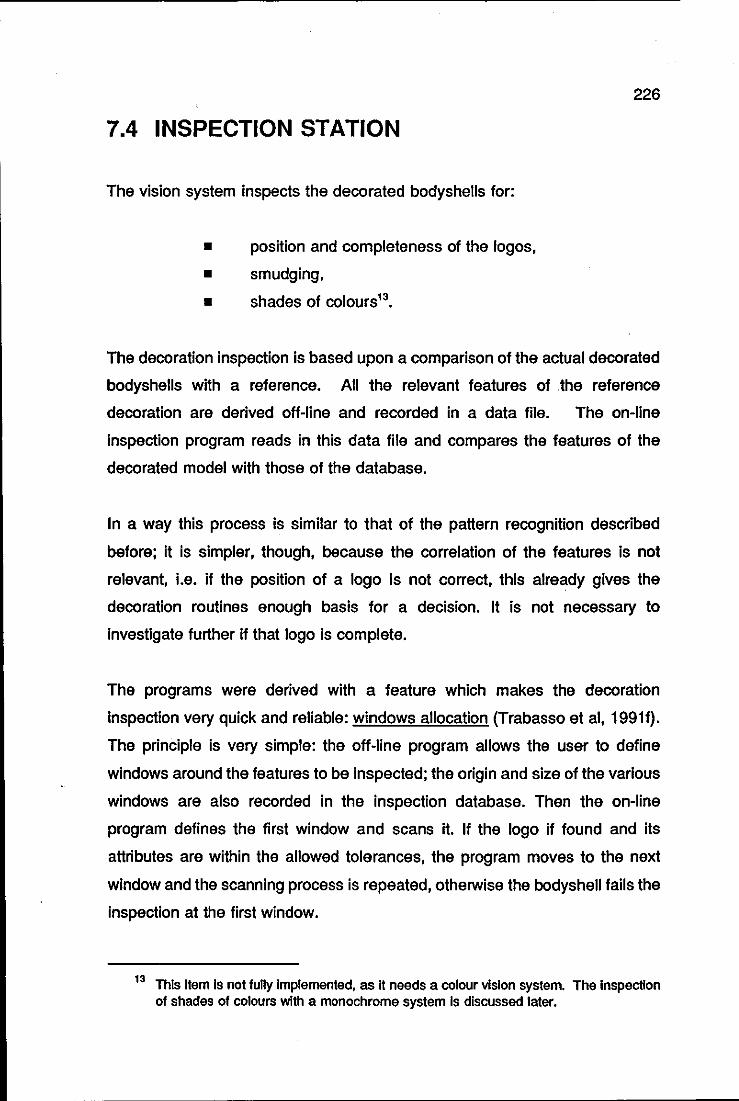
226
7.4 INSPECTION STATION
The vision system inspects the decorated bodyshells for:
• position and completeness of the logos,
• smudging,
• shades of colours13•
The decoration inspection is based upon a comparison of the actual decorated
bodyshells with a reference. All the relevant features of .the reference
decoration are derived off-line and recorded in a data file. The on-line
inspection program reads in this data file and compares the features of the
decorated model with those of the database.
In a way this process is similar to that of the pattern recognition described
before; it is simpler, though, because the correlation of the features is not
relevant, i.e. if the position of a logo is not correct, this already gives the
decoration routines enough basis for a decision. It is not necessary to
investigate further if that logo is complete.
The programs were derived with a feature which makes the decoration
inspection very quick and reliable: windows allocation (Trabasso et ai, 19911).
The principle is very simple: the off-line program allows the user to define
windows around the features to be inspected; the origin and size of the various
windows are also recorded in the inspection database. Then the on-line
program defines the first window and scans it. If the logo if found and its
attributes are within the allowed tolerances, the program moves to the next
window and the scanning process is repeated, otherwise the bodyshell fails the
inspection at the first window.
13 This Item Is not fully Implemented, as It needs a colour viSion system. The Inspection of shades of colours with a monochrome system Is discussed later.

227
The windows allocation approach allows for an enormous reduction in the
number of pixels scanned. In the bonnet inspection of the Texaco Sierra, for
example, the number of pixels scanned is reduced by 97%, from 64,53614
to
2,000 pixels.
7.4.1 GENERATION OF THE INSPECTION
DATABASE
This will be described taking as an example the decoration of the bonnet of the
Texaco Sierra. Obviously all the procedures described are as·valid for other
parts of the model, for example, the roof, left-hand side and so on, as they are
for a completely different model.
To generate the inspection database using the same conditions that will be
experienced by the on-line inspection, it is necessary to position the reference
bodyshell at the inspection station using the PUMA robot. A typical view of the
Image to be analysed by the inspection station is shown in Figure 7.16. Note
the reference marks in this figure; they are the two small white circles on the
right edge of the image. These are actually holes drilled in the print matrix and
filled with white ink. These marks are used for two purposes, firstly to check
if the matrix has been poSitioned correctly and secondly as reference positions
when checking the locations of the various parts of the decoration on the
model.
In an image with different contrast levels as is the case in this example, the
operator can split the inspection operation into two or three stages, if
necessary. In this particular example, a sensible division is to break the
inspection into light and dark features. After obtaining a binary image through
the thresholding process, the operator selects the relevant features of the
image.
14 Half resolution of the MAGISCAN vision system.
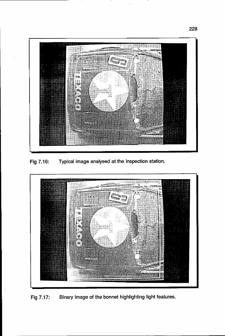
228
Fig 7.16: Typical image analysed at the inspection station.
Fig 7.17: Binary image of the bonnet highlighting light features.
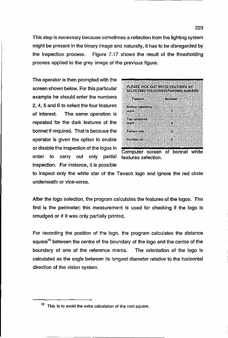
229
This step is necessary because sometimes a reflection from the lighting system
might be present in the binary image and naturally, it has to be disregarded by
the inspection process. Figure 7.17 shows the result of the thresholding
process applied to the grey image of the previous figure.
The operator is then prompted with the
screen shown below. For this particular
example he should enter the numbers
2, 4, 5 and 6 to select the four features
of interest. The same operation is
repeated for the dark features of the
bonnet if required. That is because the
operator is given the option to enable
or disable the inspection of the logos in Computer screen
order to carry out only partial features selection.
inspection. For instance, it is possible
to inspect only the white star of the Texaco logo and ignore the red circle
underneath or vice-versa.
After the logo selection, the program calculates the features of the logos. The
first is the perimeter; this measurement is used for checking if the logo is
smudged or if it was only partially printed.
For recording the position of the logo, the program calculates the distance
square15 between the centre of the boundary of the logo and the centre of the
boundary of one of the reference marks. The orientation of the logo is
calculated as the angle between its longest diameter relative to the horizontal
direction of the vision system.
15 This is to avoid the extra calculation of the root square.
230
The information about the shades of colour of the logos can also be obtained
despite the use of a monochrome vision system. This is achieved through
window allocation and the grey scale: the operator defines a small window16
which lies on a certain colour. The inspection routine then calculates the mean
grey level of the pixels inside the window according to Equation (7.33).
(7.33)
The grey scale of the MAGISCAN vision system runs from 0 (darkest) to 63
(brightest) and can be used for a great number of different numbers of shades
of colours. It has been successfully used with the bodyshell being tested, only
for the purposes of inspection. Clearly the grey scale method will fail if it is
used for Identifying colours. The gl values of black and dark blue for instance,
are so close as to make any meaningful use of them impossible. For
inspection purposes, however, no attempt to identify a particular colour is made.
The value gl is used only for comparison purposes.
After calculating the perimeter, pOSition, orientation and mean grey level of a
logo, the Inspection program prompts the operator with windows definition and
positioning. The system initially pOSitions the bottom left corner of the window
at the centre of the boundary of the logo. Then the operator defines the size
of the window and re-positions its origin in order to encompass one particular
logo. This is done using the light pen of the vision system. The process is
repeated for the rest of the logos. At this pOint the interaction between the
operator and inspection program finishes. Then the inspection data file is
generated.
16 Which contains approximately 50 pixels.
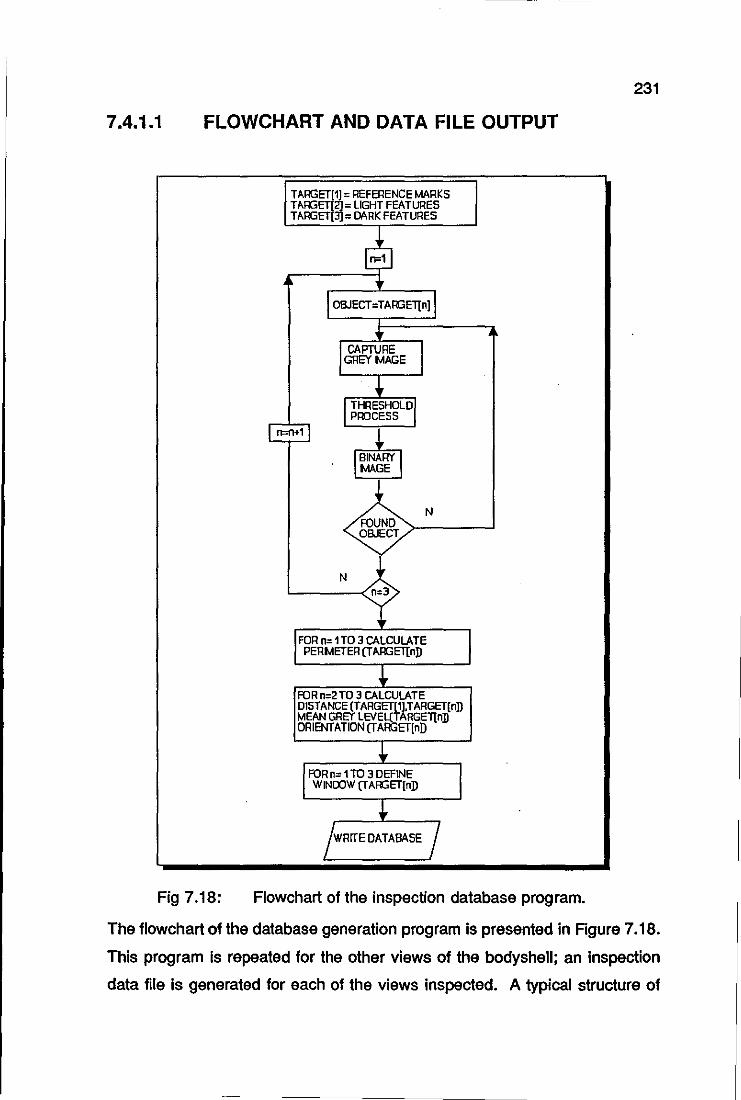
7.4.1.1 FLOWCHART AND DATA FILE OUTPUT
Fig 7.18:
TARGET(1] = REFERENCE MARKS TARGET[2]= LIGHT FEATURES TARGET[3] = DARK FEATURES
N FOUND ">-___ --' OBJECT
N '------<'n=3
FOR n= 1 TO 3 CALCULATE PERMETER (T AR3ETInD
FOR n=2TO 3 CALCULATE DISTANCE (TARGET[11.TARGET(nD MEAN GREY LEVEl(TARGEllnD ORIENTATION (TARGET[nD
FOR n= 1 TO 3 DEFINE WINDOW (TAR3ET(nD
Flowchart of the inspection database program.
231
The flowchart of the database generation program is presented in Rgure 7.18.
This program is repeated for the other views of the bodyshell; an inspection
data file is generated for each of the views inspected. A typical structure of
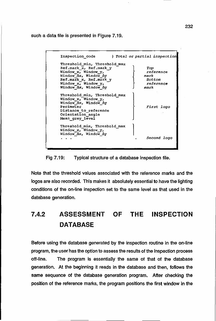
such a data file is presented in Figure 7.19.
Inspection_code } Total or partial inspection
Threshold mint Threshold max Ref.mark x, Ref.mark y -Window_x; Window-y, -Window ~, Window 6y Ref.mark_x, Ref.mark....Y Window_x, Window-y, Window _ 4x, Window _.6.y
Threshold min, Threshold max Window_x,-Window-Yt -Window Ax, Window ay
I Top reference
mark Bottom reference
mark
Per~eter - First logo Distance to reference Orientation-angle Mean_grey_level
Threshold mint Threshold max 1 Window_x,-Window-Yt -Window_~, Window_.6.y
Second logo
Fig 7.19: Typical structure of a database inspection file.
232
Note that the threshold values associated with the reference marks and the
logos are also recorded. This makes it absolutely essential to have the lighting
conditions of the on-line inspection set to the same level as that used in the
database generation.
7.4.2 ASSESSMENT DATABASE
OF THE INSPECTION
Before using the database generated by the inspection routine in the on-line
program, the user has the option to assess the results of the inspection process
off-line. The program is essentially the same of that of the database
generation. At the beginning it reads in the database and then, follows the
same sequence of the database generation program. After checking the
position of the reference marks, the program positions the first window in the
233
area where the first logo is expected to be and proceeds with the inspection
sequence: the perimeter is calculated and compared to the corresponding
database. If the difference between these two values exceeds a certain
tolerance, the bodyshell is rejected, otherwise it proceeds with the next
calculation. This process is repeated for all the decoration measurements.
7.4.3 THE ON-LINE INSPECTION PROGRAM
The main difference between this software and that of the off-line program is
the interaction with the PUMA robot, which is present in the former. After
identifying a bodyshell at the pallet, the vision system is idle until the robot
places the matrix unity on the first position in the inspection station. At this
point EAGLE calls the inspection routine in OWL. The inspection of the first
section is carried out and the vision system sends the result to the PUMA
robot. If the first section passes the inspection routine, the robot positions the
matrix unity at the second position of the station and the inspection sequence
is repeated. If it fails, the robot moves the matrix unity away from the station.
Either way the result is passed to the unloading station via EAGLE.
7.5 UNLOADING STATION
PUFFIN which controls the RTX robot is briefly reviewed in this section. It is
written in Forth and structured in elementary units named words. A word in
Forth corresponds to a procedure in Pascal or a sub-routine in VAL 11. As it
can be seen in Figure 7.20, it is very easy to follow the actions performed by
the RTX robot by just looking at the PUFFIN source code17•
17 Note that some structures common to most programming languages are written In different order In Forth. The corresponding structure of line 5 in PASCAL Is: IF DECISION = 84 THEN ...
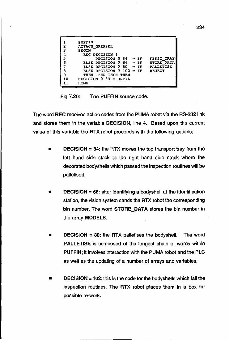
1 2 3 4 5 6 7 8 9 10 11
:PUFFIN ATTACH GRIPPER BEGIN -
REC DECISION ! DECISION @ 84 = IF
ELSE DECISION @ 66 = IF ELSE DECISION @ 80 = IF ELSE DECISION @ 102 = IF THEN THEN THEN THEN
DECISION @ 83 = UNTIL HOME
Fig 7.20: The PUFFIN source code.
FIRST TRAY STORE-DATA PALLETISE REJECT
234
The word REC receives action codes from the PUMA robot via the RS-232 link
and stores them in the variable DECISION, line 4. Based upon the current
value of this variable the RTX robot proceeds with the following actions:
• DECISION = 84: the RTX moves the top transport tray from the
left hand side stack to the right hand side stack where the
decorated bodyshells which passed the inspection routines will be
palletised,
Ii DECISION = 66: after identifying a bodyshell at the identification
station, the vision system sends the RTX robot the corresponding
bin number. The word STORE_DATA stores the bin number in
the array MODELS.
• DECISION = 80: the RTX palletises the bodyshell. The word
PALLETISE is composed of the longest chain of words within
PUFFIN; it involves interaction with the PUMA robot and the PLC
as well as the updating of a number of arrays and variables.
• DECISION = 102: this is the code for the bodyshells which fail the
inspection routines. The RTX robot places them in a box for
possible re-work.
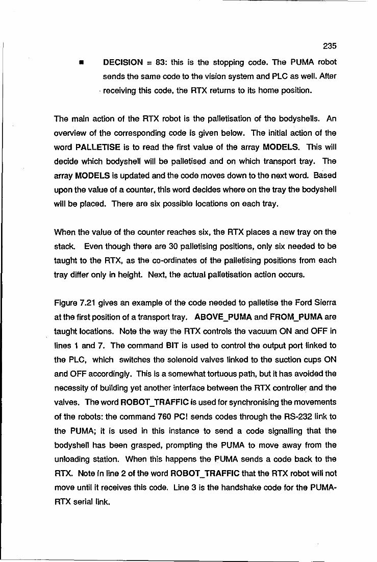
235
• DECISION = 83: this is the stopping code. The PUMA robot
sends the same code to the vision system and PLC as well. After
. receiving this code, the RTX returns to its home position.
The main action of the RTX robot is the palletisation of the bodyshells. An
overview of the corresponding code is given below. The initial action of the
word PALLETISE is to read the first value of the array MODELS. This will
decide which bodyshell will be palletised and on which transport tray. The
array MODELS Is updated and the code moves down to the next word. Based
upon the value of a counter, this word decides where on the tray the bodyshell
will be placed. There are six possible locations on each tray.
When the value of the counter reaches six, the RTX places a new tray on the
stack. Even though there are 30 palletising positions, only six needed to be
taught to the RTX, as the co-ordinates of the palletising positions from each
tray differ only in height. Next, the actual palletisation action occurs.
Figure 7.21 gives an example of the code needed to palletise the Ford Sierra
at the first position of a transport tray. ABOVE_PUMA and FROM_PUMA are
taught locations. Note the way the RTX controls the vacuum ON and OFF in
lines 1 and 7. The command BIT is used to control the output port linked to
the PLC, which switches the solenoid valves linked to the suction cups ON
and OFF accordingly. This Is a somewhat tortuous path, but it has avoided the
necessity of building yet another interface between the RTX controller and the
valves. The word ROBOT_TRAFFIC is used for synchronising the movements
of the robots: the command 760 PCI sends codes through the RS-232 link to
the PUMA; it is used in this instance to send a code signalling that the
bodyshell has been grasped, prompting the PUMA to move away from the
unloading station. When this happens the PUMA sends a code back to the
RTX. Note in line 2 of the word ROBOT_TRAFFIC that the RTX robot will not
move until it receives this code. Line 3 is the handshake code for the PUMA
RTX serial link.
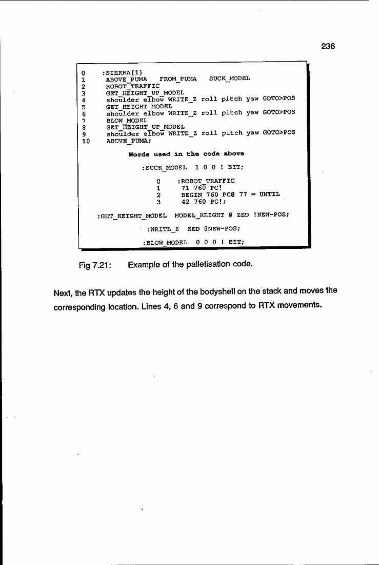
0 1 2 3 4 5 6 7 8 9 10
:SIERRA(l) ABOVE PUMA FROM PUMA SUCK MODEL ROBOT-TRAFFIC GET HEIGHT UP MODEL shoulder eLbow WRITE Z roll pitch yaw GOTO>POS -GET HEIGHT MODEL shoulder eLbow WRITE Z roll pitch yaw GOTO>POS BLOW MODEL GET HEIGHT UP MODEL shoulder eLbow WRITE_ Z roll pitch yaw GOTO>POS ABOVE_PUMA;
Words used in the code above
:SUCK MODEL 1 0 0 ! BIT;
o :ROBOT TRAFFIC 1 71 760 PC! 2 BEGIN 760 PC@ 77 = UNTIL 3 42 760 PC!;
:GET HEIGHT MODEL MODEL_HEIGHT @ ZED !NEW-POS;
:WRITE Z ZED @NEW-POS;
:BLOW MODEL 0 0 0 ! BIT;
Fig 7.21: Example of the palletisation code.
236
Next, the RTX updates the height of the bodyshell on the stack and moves the
corresponding location. Lines 4, 6 and 9 correspond to RTX movements.
237
CHAPTER 8
MECHATRONIC DECORATION CELL:
OPERATION AND CONTROL
MECHATRONIC DECORATION CELL
OPERATION AND CONTROL
OPERATION
WORK CYCLE
START UP PROCEDURE
FLEXIBILITY ASSESSMENT
CONTROL
SEQUENTIAL CONTROL
OPERATOR INTERFACE
SAFETY MONITORING
RECOVERY STRATEGIES
239
SUMMARY
Chapters 5 to 7 presented the Mechatronics design of the decoration cell
through its component stations. The Mechatronics design methodology used
produced elements of integration built into the stations; this is highlighted in the
operational cycle of the cell described in Section 8.1.
The decoration cell operator interface is described in the start up procedures
of the cell as well as in the emergency procedures. A knowledge base system
holds the relevant information about the cell operation and can be used by the
operator in the form of a consultation session. The description of the cell
operation ends with an analysis of a complete changeover of the cell. This
gives the opportunity to assess the flexibility capability of the cell.
Finally, a down-to-earth cell control philosophy with embedded recovery
strategies is described in Section 8.2.

'TI cO' !» ..... INJECTION
MOULDING MACHINE
D
u«COR'TED SCALE HOOa
LOADING STATION
TO THE FINAL ASSEMBLY
mm mm
UNLOADING STATION
~ f=
RTX
PALLET CONVEYOR BELT
VISION ~ SYSTE-;:.M:..J..!:::~==::...J....,
B
fD] f~
EJ G
IDENTIFICATION ,--, STATION [IIJI
L--J
~
~
tCO CAMERA
,~LiF~'S INSPECTION STATION PUMA560
CAD IIDRKSTATION .CESI~ • SI I'IJLA TION .OfF-LINE
PRIXRAHHINC
EXPERT IF"\ SYSTEM ~
r
TAMPING MACHINE
co • ...&.
o "'C m ::c ~ -o z
241
A schematic layout of the decoration cell is shown in Figure 8.1. All the items
except the injection moulding machine are installed at the Department of
Mechanical Engineering, Loughborough University of Technology, and are
presently operational. It is necessary to mention that six more cliches are
necessary for the completion of the decoration of the particular model that trials
are being conducted on, even though only one printing machine is actually
linked to the cell and shown in this figure.
8.1.1 WORK CYCLE
The work cycle of the decoration cell is described following the various stages
through which an undecorated model is taken to its final decoration: after
leaving the moulding machine, the bodyshells are inspected for flash and
moulding flaws; they are then conveyed to the loading station where tM
bodyshells are stacked. The loading mechanism transfers the bodyshells from
the chute to the conveyor pallet by a combination of angular and linear
displacements.
Then the bodyshells are conveyed to the identification station where the CCD
camera mounted on the PUMA robot arm is used to take a photograph of the
scene. This is analysed by the vision system which identifies the model and
sends to the PUMA the orientation angle and the co-ordinates1 of the centre
of boundary of the bodyshell. With this information, the PUMA controller
composes the location of the pick point of the bodyshell and drives the robot
to pick it up. The bodyshell is placed at the re-positioning device, the PUMA
changes the end-effector from jaws to suction and places the bodyshell onto
a print matrix for the decoration process.
The decoration process is carried out by the interaction of the PUMA robot with
1 Already expressed in the robot world co-ordinate system.
242
the pad printing machine. In the current approach, the PUMA robot places the
matrix unit at the first printing position and the printing cycle is executed. Then,
the robot moves the matrix unit to the next printing position, the printing cycle
is executed once again, and so on. After finishing the logo placement at the
first printing machine the robot moves the bodyshell to the second machine and
the process is repeated up to the last printing machine when the decoration is
completed. Next, the PUMA robot places the decorated bodyshell at the first
position of the locating mechanism of the inspection station. Th~ee
photographs are taken and analysed: top, left and right hand sides. If this first
subset of the decoration is correct, the robot moves the bodyshell to the next
position of the locating mechanism and the inspection cycle is repeated,
otherwise, the bodyshell is moved away from the station.
Finally, the models that have been accepted by the inspection station are
picked up by the RTX robot directly from the PUMA robot and palletised for
final assembly at the unloading station. The rejected bodyshells are also picked
up and placed in a bin for possible rework or scrap.
8.1.2 START UP PROCEDURE
What has been described above refers to the on-line operation of the
decoration cell. Naturally the intervention of an operator is required to initialise
the work cycle of the cell. The sequence of steps necessary to start the cell
running will be referred to as start up procedure from now on; it is described as
follows: first the operator switches on the mains supply of the following
components of the decoration cell:
• PUMA robot controller,
• Vision system controller and the associated cameras,
• Conveyor system motors,
• PLC and associated DC power supply,
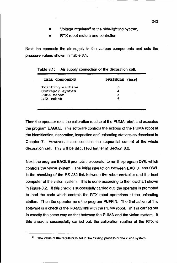
243
• Voltage regulator of the side-lighting system,
• RTX robot motors and controller.
Next, he connects the air supply to the various components and sets the
pressure values shown in Table 8.1.
Table 8.1: Air supply connection of the decoration cell.
CELL COMPONENT
Printing machine Conveyor system PUMA robot RTX robot
PRESSURE (bar)
6 4 3 6
Then the operator runs the calibration routine of the PUMA robot and executes
the program EAGLE. This software controls the actions of the PUMA robot at
the identification, decoration, inspection and unloading stations as described in
Chapter 7. However, it also contains the sequential control of the whole
decoration cell. This will be discussed further in Section 8.2.
Next, the program EAGLE prompts the operator to run the program OWL which
controls the vision system. The initial interaction between EAGLE and OWL
is the checking of the RS-232 link between the robot controller and the host
computer of the vision system. This is done according to the flowchart shown
in Figure 8.2. If this check is successfully carried out, the operator is prompted
to load the code which controls the RTX robot operations at the unloading
station. Then the operator runs the program PUFFIN. The first action of this
software is a check of the RS-232 link with the PUMA robot. This is carried out
in exactly the same way as that between the PUMA and the vision system. If
this check is successfully carried out, the calibration routine of the RTX is
2 The value of the regulator Is set In the training process of the vision system.
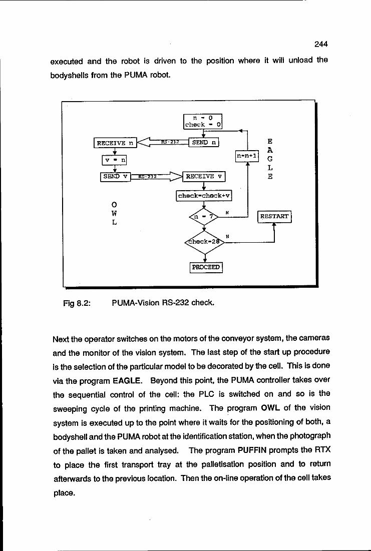
244
executed and the robot is driven to the position where it will unload the
bodyshells from the PUMA robot.
Fig 8.2:
RECEIVE n
o W L
n - 0 check - 0
SEND n E A G L E
heck-2B>------I
PUMA-Vision RS-232 check.
Next the operator switches on the motors of the conveyor system, the cameras
and the monitor of the vision system. The last step of the start up procedure
Is the selection of the particular model to be decorated by the cell. This is done
via the program EAGLE. Beyond this point, the PUMA controller takes over
the sequential control of the cell: the PLC is switched on and so is the
sweeping cycle of the printing machine. The program OWL of the vision
system is executed up to the point where it waits for the positioning of both, a
bodyshell and the PUMA robot at the identification station, when the photograph
of the pallet is taken and analysed. The program PUFFIN prompts the RTX
to place the first transport tray at the palletisation position and to return
afterwards to the previous location. Then the on-line operation of the cell takes
place.
245
Naturally it is assumed that the set up of the printing machine, the generation
of the inspection, pattern recognition and vision-PUMA calibration databases
have already been executed before the start up procedure just described.
After executing the start up procedure of the cell a number of times, the
operator will eventually get used to it and this will become but a mere sequence
of steps to be followed. It was felt, however, that some form of aid for the
operator to execute the start up procedure was a suitable idea. This would
help the trained operator with the checking of any doubtful point about the
procedure and help immensely with the training of newcomers.
Such an aid could have been a simple instruction sheet. The approach
adopted, however, is far more efficient and it takes place in the form of a
consultation by the operator to a knowledge base system which contains all the
relevant information about the cell operation. The expert system shell Savoir
(Intelligent Systems, 1987) was used for this purpose. This application of the
expert system will be described in Chapter 9, where two more artificial
intelligence applications which use the same expert system are discussed in
detail.
8.1.3 FLEXIBILITY ASSESSMENT
Scale model decoration is an area which demands flexibility in production. This
happens because sponsors names, racing numbers and colour schemes are
frequently changed from one season to the other. One bodyshell often has
many different sets of decorations. Sometimes a customised decoration is also
required. The present factory based method is fairly flexible but the time
required for achieving the production of a new decoration outweighs its
flexibility.
The problem of rendering the decoration cell flexible was tackled throughout its
design: flexibility is embedded in the mechatronics approach to design. The
246
result can be easily assessed through the stations of the cell. All but the
decoration station can be easily and quickly re-programmed to execute a new
decoration layout. No special jigs were used so that much of the bulk of the
cell hardware remains unchanged when a different decoration is to take place.
The majority of modifications are related to software: re-teaching the new
locations to the robots and generation of new databases for the identification
and inspection stations. In order to draw a clearer picture of the cell flexibility,
the scenario of a complete cell changeover to decorate a different bodyshell
with a different decoration layout is discussed below. The following alterations
have to be carried out:
I) AT THE LOADING STATION
L 1) Replacement of the feeding chute,
L2) Vertical adjustment of the handling mechanism.
Ii) AT THE IDENTIFICATION STATION
11) Generation of the pattern recognition database of the model,
12) Replacement of the matrix end-effector of the PUMA robot,
13) Teaching of the matrix location to the PUMA robot.
Ill) AT THE DECORATION STATION
01) Setting up of the printing machines,
02) Teaching of the printing locations to the PUMA robot.
Iv) AT THE INSPECTION STATION
S1) Generation of the inspection database of the model,
S2) Adjustments of the cameras.
v) AT THE UNLOADING STATION
U1) Replacement of the transport trays,
U2) Teaching of the palletisation locations to the RTX robot.
/~
247
By recalling the characteristics of the setting up of the pad printing machines
presented in Section 2.3.3.1, one readily realises that item (01) hampers any
attempt at a quick cell changeover. All but this item can be carried out
speedily. The teaching of the robots might present some difficulties, but the cell
has available an off-line programming facility whose use will make sense only
if a reasonable solution to item (01) is found. In other words, if the cell has
to cease the work cycle to allow the setting up of all the printing machines, then
there is plenty of time for recording the new robot locations using their teach
pendants. The off-line programming facility of the cell is presented in Chapter
9.
8.1.3.1 MODULAR DECORATION STATION
One way of speeding up the decoration cell changeover is to have the
decoration station as a detachable module (Trabasso et ai, 1991d). Suppose
that the cell is at the final stages of a batch run of a particular model. At the
same time, the set of printing machines to be used in the new model could start
to be set up independently of the cell work cycle. After finishing the batch run,
the set of machines of the previous model would be removed from the cell and
the new set of machines would then be plugged into it. In this approach, the
off-line programming of the robots does make sense, as the new robot
locations could be taught at the same time that the cell is still operating with the
old model.
8.2 CONTROL
The cell controller consists of the PUMA control unit and a PLC. The vision
system and the RTX robot have their own controllers, but the cell controller may
overrule them whenever necessary. This also applies to the PUMA controller
itself, i.e, a task being executed by the PUMA might be interrupted by the cell
248
control, even though the source of both controls is the same PUMA controller.
This is possible because of the interrupt calls from the VAL 11 language that can
be used with different levels of priority. A VAL II interrupt call has the following
structure:
REACT <signal>, <routine>, <priority>
Priority defines the hierarchy of the routine execution; the minimum value is 1
and the maximum is 127. When the user writes a program, priority 1 is
assigned to the program by default. Suppose that the user's program has the
command:
REACT 1010, shutdown, 127
In parallel with the execution of the main program, the robot controller monitors
the signal 1010. When it is high, the controller interrupts the execution of the
main program (priority 1) and executes the sub-routine shutdown. After
finishing the execution of this routine, the controller resumes the execution of
the previous program.
The three functions usually associated with the cell controller, namely,
sequence control, operator interface and safety monitoring (Thomas, 1983),
were implemented into the cell and they are described as follows.
8.2.1 SEQUENTIAL CONTROL
The PLC handles all the operations relating to the conveyor system and the
loading station; the PUMA controller is used for coordinating the rest of the
activities of the decoration cell, namely, the supervision of the vision system,
the RTX robot, the inspection station and the interaction with the pad printing
machine. The sequential control has embedded recovery strategies that allow
for a low level intervention in the decoration process. The recovery strategy
routines of the cell are described in Section 8.2.4.

249
8.2.2 OPERATOR INTERFACE
Most of interaction between the operator and the decoration cell takes place in
the start up procedure of the cell. Refer to Section 8.1.1. In the on-line
operation, operator intervention is only required in the case of emergency stop
conditions. The reason for the emergency may be an irregularity in the
decoration cell that is potentially damaging to the robots or other equipment of
the cell.
An irregular event in the work cycle might be that the PUMA has not fitted an
end effector properly and that would cause problems with the printing machine
interaction and with the robot tooling itself. In this case the operator would
have reasons to interrupt the operational cycle of the cell until the emergency
situation was corrected. The means for achieving this are:
• Individual emergency stop switches (also called panic
switches) located at the components of the cell. They are
present in the PUMA and RTX robots, conveyor system and
printing machine.
• Global emergency stop switch which halts the operation of the
whole cell, excepting the motors of the conveyor system. This
switch is linked to a interrupt routine in EAGLE which has the
highest possible priority level. It triggers a stopping routine which
switches off the vision system and the printing machine, drives
the RTX robot to its home position and switches off the motors of
the PUMA robot.
8.2.3 SAFETY MONITORING
Because the decoration cell is currently placed in a university research
laboratory, it is believed that the safeguards in place are enough for safety
250
monitoring as far as operator safety is concerned: the cell is surrounded by a
fence and security warnings are boldly displayed. Naturally the safety
monitoring has to be lighten for an industrial environment. With regards to
monitoring operational deviations, a detailed approach to the problem is
discussed in Section 8.2.4
8.2.4 RECOVERY STRATEGIES
In order to achieve a low level of human intervention in the decoration process,
the sequential control has embedded recovery strategy rules which are
triggered as soon as the sequential control monitoring sensors indicate that a
non desired path or sequence has taken place. Some researchers would call
this procedure an error recovery strategy. The author, however, favours
omitting the word error. It is believed that if one can actually plan to sense an
error or an anomalous event and recover from it, then it is not an error at all
(Trabasso et aI, 1990b). These errors are simply events in a plan and referred
to from now on as deviation events. The events that lead to a desired situation
are denominated goal events. At the loading station, for example, the goal
event is to take one model out of the feeding chute using the loading
mechanism and place it onto the pallet. A possible deviation event is if the
mechanism drops the model before reaching the pallet.
The recovery strategy presently embedded in the sequential control is attained
by introducing sensing steps and conditionals. Even though this strategy can
be regarded as an ad hoc one, it was chosen because the task of identifying
possible deviation events in the decoration process produced a very significant
number of situations that the sequential control program could actually recover
from.
The framework of the recovery strategy is described below: each station has
sensors to indicate the presence of deviation events. These sensors are
referred to as deviation sensors in order to differentiate them from the rest of
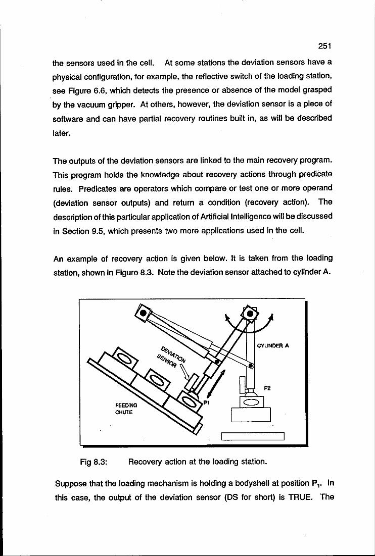
251
the sensors used in the cell. At some stations the deviation sensors have a
physical configuration, for example, the reflective switch of the loading station,
see Figure 6.6, which detects the presence or absence of the model grasped
by the vacuum gripper. At others, however, the deviation sensor is a piece of
software and can have partial recovery routines built in, as will be described
later.
The outputs of the deviation sensors are linked to the main recovery program.
This program holds the knowledge about recovery actions through predicate
rules. Predicates are operators which compare or test one or more operand
(deviation sensor outputs) and return a condition (recovery action). The
description of this particular application of Artificial Intelligence will be discussed
in Section 9.5, which presents two more applications used in the cell.
An example of recovery action is given below. It is taken from the loading
station, shown In Figure 8.3. Note the deviation sensor attached to cylinder A.
Fig 8.3:
FEEDING CHU1"E
Recovery action at the loading station.
Suppose that the loading mechanism is holding a bodyshell at position PI. In
this case, the output of the deviation sensor (OS for short) is TRUE. The

252
recovery program acknowledges that the OS output should stay TRUE until the
mechanism gets to position P 2' where the bodyshell is placed onto the pallet.
Elaborating upon a possible deviation event where the mechanism drops the
bodyshell before completing the loading cycle, the OS output, now FALSE,
triggers a software alarm to the recovery program. The pallet at the loading
station is released and the program tries to locate the cause of the failure by
seeking answers to the following questions:
a) is it a global air failure ?
b) is it an air failure at the loading station?
c) is it a mechanism failure?
If the answers to (a) or (b) are TRUE, the software will trigger an alarm asking
for maintenance intervention, showing the area of the failure; this is an example
of a true error, an error that the program cannot recover from. If, on the other
hand, these answers are FALSE, the recovery program can conclude that (c)
is TRUE and will drive the loading mechanism to its initial position and re-start
the loading cycle. If it is a recurrent error, the program will ask for the help of
an operator. Simple rules such as that stated above can easily be drawn for
all stages of the decoration process.
It was mentioned earlier that some deviation sensors are actually pieces of
software, instead of having a physical configuration. This is shown at the
decoration station. The operation of positioning the model matrix in the printing
machine by the PUMA robot is essentially the robotic operation of putting a peg
in a hole, as shown in Figure 8.4. When the robot starts moving from Pl to P2,
a routine samples the distance d, at time t l, see Figure 8.5. At time tl+k' the
distance d'+k is also sampled and compared with d,. If d'+k is equal to d
" the
routine senses that the robot arm did not move between the two time intervals
as a result, for example, of a possible contact between points P3 and P4 , and
immediately takes the recovery action of moving the arm back to position Pl .
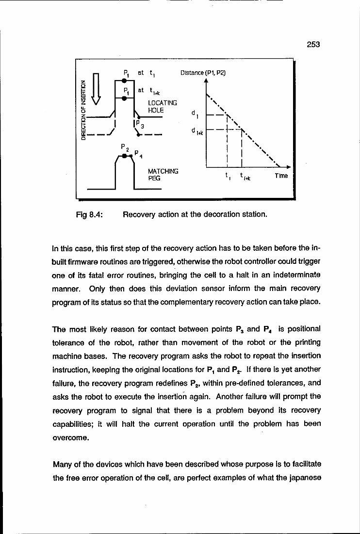
253
In P, at t,
P, at thl:
LOCATING
Distance (Pl, P2)
IL HOLE 0 I " z Q
I IP 3 ~ 9;--'/ \:--Cl
nP2
,p __
4
__ MATCHING PEG
-_ ..... t, t 1+1: Time
Fig 8.4: Recovery action at the decoration station.
In this case, this first step of the recovery action has to be taken before the in
built firmware routines are triggered, otherwise the robot controller could trigger
one of its fatal error routines, bringing the cell to a halt in an indeterminate
manner. Only then does this deviation sensor inform the main recovery
program of its status so that the complementary recovery action can take place.
The most likely reason for contact between points P3 and P4 is positional
tolerance of the robot, rather than movement of the robot or the printing
machine bases. The recovery program asks the robot to repeat the insertion
instruction, keeping the original locations for P, and P2• II there is yet another
failure, the recovery program redefines P2, within pre-delined tolerances, and
asks the robot to execute the insertion again. Another failure will prompt the
recovery program to signal that there is a problem beyond its recovery
capabilities; it will halt the current operation until the problem has been
overcome.
Many of the devices which have been described whose purpose is to facilitate
the free error operation of the cell, are perfect examples of what the japanese

· 254
term 'poka-yoke'. Poka-yoke means roughly 'mistake-proof'. Shingo (1986) .
describes many examples of poka-yoke devices and systems; the design of
these devices is an ideal example of simple and effective Mechatronics.
255
CONCLUSION
Following the various stages through which an undecorated model is taken to
its final decoration gives the reader a clear picture of the integration between
the stations of the decoration cell. This is a direct consequence of the
Mechatronics design philosophy used in the cell.
Excluding the setting up of the printing machine, it can be readily observed that
the workload of the operator for starting up the cell and running it afterwards
is very light.
With regards to the control of the decoration cell, the current approach can be
replaced by a central cell controller. That is, instead of having the control split
between the PLC and the PUMA controller, it could be hosted in a single
machine, the cell controller.

256
CHAPTER 9
TOPICS FOR FURTHER RESEARCH

TOPICS FOR FURTHER RESEARCH
MECHATRONIC TOOL CHANGER
MATRIX-ON-BEL T APPROACH TO
DECORATION
OFF-LINE PROGRAMMING
INFRA-RED END-EFFECTOR
ARTIFICIAL INTELLIGENCE APPLICATIONS
258
SUMMARY
The title of this chapter might prove to be misleading in a sense that it suggests
to the reader that vague and unexplored ideas about the continuation of the
project will be presented.
On the contrary, the chapter presents five original topics for further research
which have already received considerable attention. Some of them have
reached the prototype phase, as it is the case of the suck and blow tool
changer which is now being considered for a patent and the infra-red end
effector. Others are already operational but not linked to the decoration cell,
as is the case with the start up procedure of the cell, implemented with the aid
of an expert system shell.
The main characteristic of the topics presented is that they already have their
main core developed and would be operating within the cell if the author had
had time to complete their final configurations.
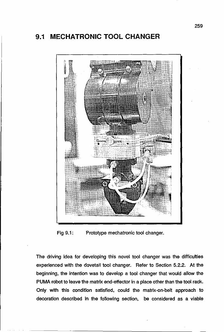
259
9.1 MECHATRONIC TOOL CHANGER
Fig 9.1: Prototype mechatronic tool ch anger.
The driving idea for developing this novel tool changer was the difficulties
experienced with the dovetail tool changer. Refer to Section 5.2.2. At the
beginning, the intention was to develop a tool changer that would allow the
PUMA robot to leave the matrix end-effector in a place other than the tool rack.
Only with this condition satisfied, could the matrix-on-belt approach to
decoration described in the following section, be considered as a viable
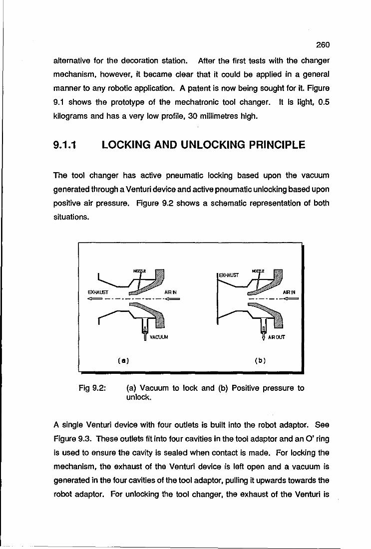
260
alternative for the decoration station. After the first tests with the changer
mechanism, however, it became clear that it could be applied in a general
manner to any robotic application. A patent is now being sought for it. Figure
9.1 shows the prototype of the mechatronic tool changer. It is light, 0.5
kilograms and has a very low profile, 30 millimetres high.
9.1.1 LOCKING AND UNLOCKING PRINCIPLE
The tool changer has active pneumatic locking based upon the vacuum
generated through a Venturi device and active pneumatic unlocking based upon
positive air pressure. Figure 9.2 shows a schematic representation of both
situations.
~------------~
Fig 9.2:
VACULI.1 AROUT
( 5) (b)
(a) Vacuum to lock and (b) Positive pressure to unlock.
A single Venturi device with four outlets is built into the robot adaptor. See
Figure 9.3. These outlets fit into four cavities in the tool adaptor and an 0' ring
Is used to ensure the cavity is sealed when contact is made. For locking the
mechanism, the exhaust of the Venturi device is left open and a vacuum is
generated in the four cavities of the tool adaptor, pulling it upwards towards the
robot adaptor. For unlocking the tool ch anger, the exhaust of the Venturi is
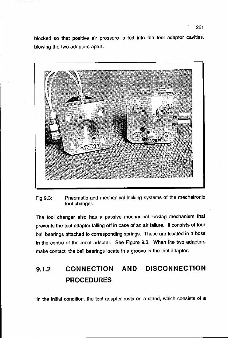
261
blocked so that positive air pressure Is fed into the tool adaptor cavities,
blowing the two adaptors apart.
Fig 9.3: Pneumatic and mechanical locking systems of the mechatronic tool changer.
The tool ch anger also has a passive mechanical locking mechanism that
prevents the tool adapter falling off in case of an air failure. It consists of four
ball bearings attached to corresponding springs. These are located in a boss
in the centre of the robot adapter. See Figure 9.3. When the two adaptors
make contact, the ball bearings locate in a groove in the tool adaptor.
9.1.2 CONNECTION AND DISCONNECTION
PROCEDURES
In the initial condition, the tool adapter rests on a stand, which consists of a
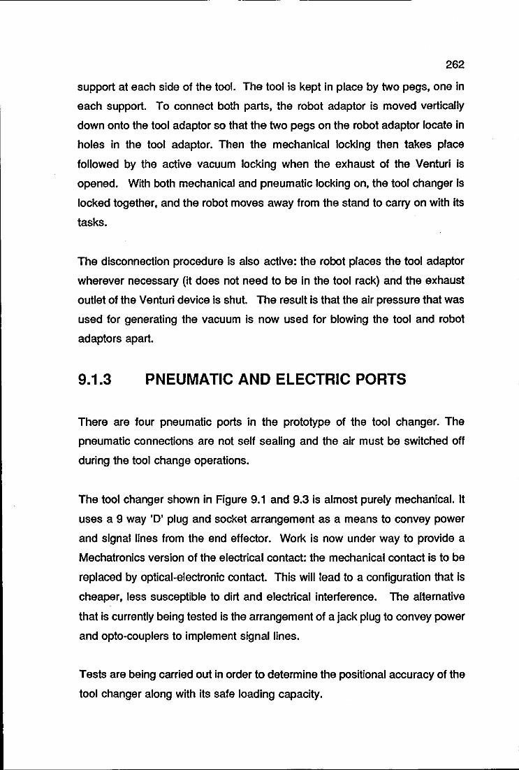
262
support at each side of the tool. The tool is kept in place by two pegs, one in
each support. To connect both parts, the robot adaptor is moved vertically
down onto the tool adaptor so that the two pegs on the robot adaptor locate in
holes in the tool adaptor. Then the mechanical locking then takes place
followed by the active vacuum locking when the exhaust of the Venturi is
opened. With both mechanical and pneumatic locking on, the tool changer is
locked together, and the robot moves away from the stand to carry on with its
tasks.
The disconnection procedure is also active: the robot places the tool adaptor
wherever necessary (it does not need to be in the tool rack) and the exhaust
outlet of the Venturi device is shut. The result is that the air pressure that was
used for generating the vacuum is now used for blowing the tool and robot
adaptors apart.
9.1.3 PNEUMATIC AND ELECTRIC PORTS
There are four pneumatic ports in the prototype of the tool ch anger. The
pneumatic connections are not self sealing and the air must be switched off
during the tool change operations.
The tool changer shown in Figure 9.1 and 9.3 is almost purely mechanical. It
uses a 9 way '0' plug and socket arrangement as a means to convey power
and signal lines from the end effector. Work is now under way to provide a
Mechatronics version of the electrical contact: the mechanical contact is to be
replaced by optical-electronic contact. This will lead to a configuration that is
cheaper, less susceptible to dirt and electrical interference. The alternative
that is currently being tested is the arrangement of a jack plug to convey power
and opto-couplers to implement signal lines.
Tests are being carried out in order to determine the positional accuracy of the
tool changer along with its safe loading capacity.
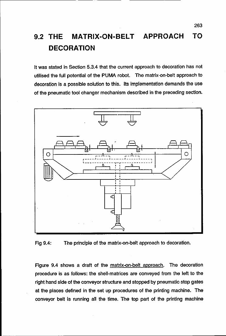
263
9.2 THE MATRIX-ON-BEL T APPROACH TO
DECORATION
It was stated in Section 5.3.4 that the current approach to decoration has not
utilised the full potential of the PUMA robot. The matrix-on-belt approach to
decoration is a possible solution to this. Its implementation demands the use
of the pneumatic tool changer mechanism described in the preceding section.
o ~----------~~~_~_~,~--~~~_~_~,----+-----~ 0
Fig 9.4:
r----~-----~-----~-----·----, L------------~-r------------~ , , , ,
, ,
The principle of the matrix-on-belt approach to decoration.
Figure 9.4 shows a draft of the matrix-on-belt approach. The decoration
procedure is as follows: the shell-matrices are conveyed from the left to the
right hand side of the conveyor structure and stopped by pneumatic stop gates
at the places defined in the set up procedures of the printing machine. The
conveyor belt is running all the time. The top part of the printing machine
264
workplace is pneumatically raised above the conveyor structure, with the
locating pegs matching the guide holes of the shell-matrix units. The rubber
pads come down and the motifs are transferred onto the bodyshells. Then, the
workpieces are lowered and the stop gates are opened; the bodyshell that was
at the left hand side stop gate is stopped at the next gate; another bodyshell
now occupies its place; the bodyshell that has received both decorations is now
at the end of the conveyor structure, awaiting loading by the robot onto the next
printing machine.
For the setting up operations of the print machine, one has only to activate the
lifting device of the unity and proceed with the operations in the usual manner
as the print matrices are positioned above the conveyor structure.
To perceive the benefits of this method, one has to recall the scenario of seven
pad printing machines interacting with the robot in order to decorate the
bodyshells fully. This time, all the printing machines are fitted with the conveyor
structures shown in Figure 9.4. The robot initially loads the first printing
machine with a number of shell-matrix units. After printing the bonnet and roof
of the first bodyshell, the robot transfers this shell-matrix unit to the second
printing machine. As the second machine is decorating the sides of the
bodyshells, the first machine is decorating a second bodyshell, simultaneously.
Next, the robot transfers the first shell-matrix unity from the second to the third
machine and then, the second shell-matrix unity from the first to the second
printing machine, and so forth.
Even though this approach was primarily devised for being operated by the
PUMA robot, it is also possible to implement it without the robot. To this end,
it is necessary to have mechanisms for transferring the bodyshells from one
printing machine to the other. These mechanisms could be as simple as that
of the loading station. Because this solution brings a substantial reduction in
the cost of the decoration cell, it is now receiving great consideration. The first
prototype of the approach is currently being built.
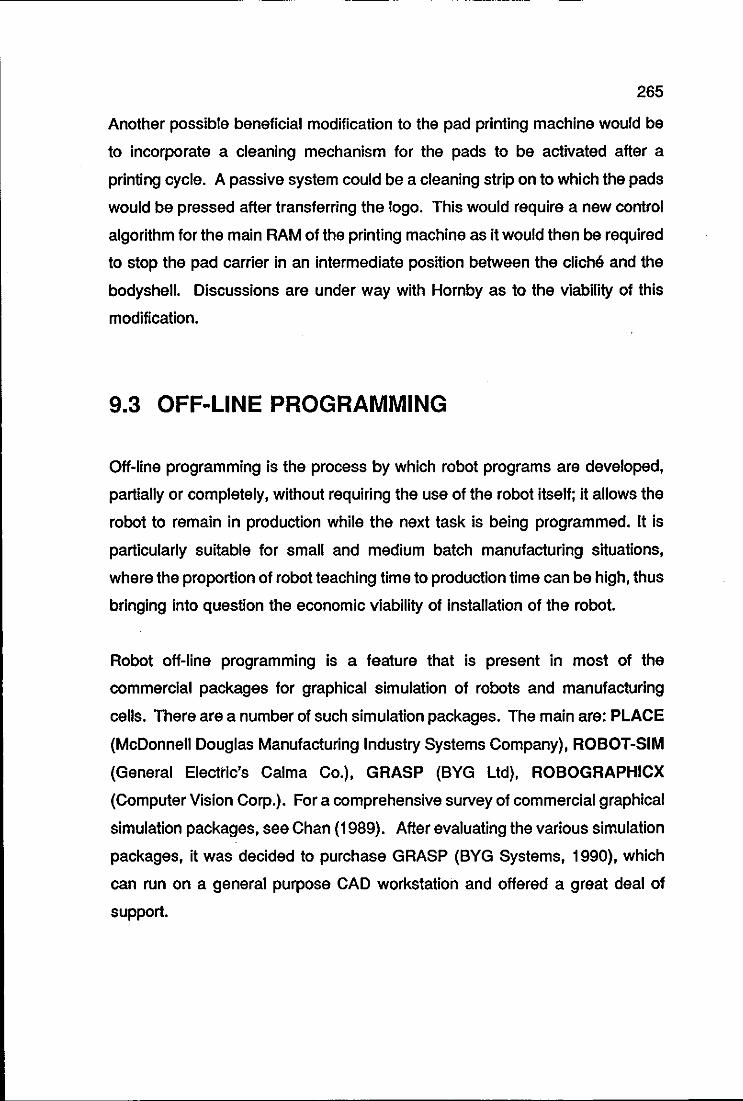
265
Another possible beneficial modification to the pad printing machine would be
to incorporate a cleaning mechanism for the pads to be activated after a
printing cycle. A passive system could be a cleaning strip on to which the pads
would be pressed after transferring the logo. This would require a new control
algorithm for the main RAM of the printing machine as it would then be required
to stop the pad carrier in an intermediate position between the cliche and the
bodyshell. Discussions are under way with Hornby as to the viability of this
modification.
9.3 OFF-LINE PROGRAMMING
Off-line programming is the process by which robot programs are developed.
partially or completely. without requiring the use of the robot itself; it allows the
robot to remain in production while the next task is being programmed. It is
particularly suitable for small and medium batch manufacturing situations.
where the proportion of robot teaching time to production time can be high. thus
bringing into question the economic viability of installation of the robot.
Robot off-line programming is a feature that is present in most of the
commercial packages for graphical simulation of robots and manufacturing
cells. There are a number of such simulation packages. The main are: PLACE
(McDonnell Douglas Manufacturing Industry Systems Company). ROBOT-SI M
(General Electric's Calma Co.). GRASP (BYG Ltd). ROBOGRAPHICX
(Computer Vision Corp.). For a comprehensive survey of commercial graphical
simulation packages. see Chan (1989). After evaluating the various simulation
packages. it was decided to purchase GRASP (BYG Systems. 1990). which
can run on a general purpose CAD workstation and offered a great deal of
support.
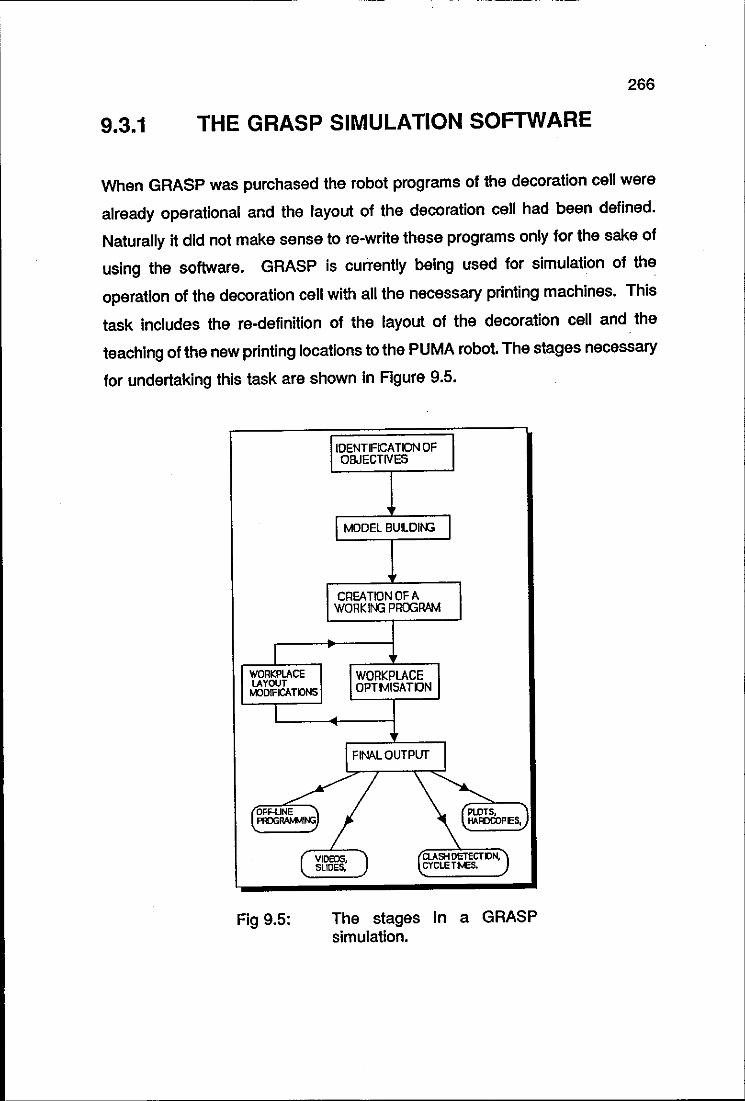
266
9.3.1 THE GRASP SIMULATION SOFTWARE
When GRASP was purchased the robot programs of the decoration cell were
already operational and the layout of the decoration cell had been defined.
Naturally it did not make sense to re-write these programs only for the sake of
using the software. GRASP is currently being used for simulation of the
operation of the decoration cell with all the necessary printing machines. This
task includes the re-definition of the layout of the decoration cell and the
teaching of the new printing locations to the PUMA robot. The stages necessary
for undertaking this task are shown in Figure 9.5.
IIDENTIFICA TION OF OBJECTIVES
I MODEL BUILDII'G
. CI'lEA TION OF A
WORKIN3 PROGRAM
I WORKPLACE I WORKPLACE I LAYOUT !.(JOIfICATDNS OPTMISATIJN
1
I FINAL OUTPUT I
~~~l PROGlWo'MltG \~ , I1AFDCOPES, )
Fig 9.5:
(VIDEOS, ) SLIDES,
~Q.A5H DETECTDN, CYCLETNE5.
The stages in a GRASP simulation.
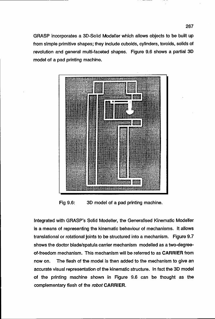
267
GRASP incorporates a 3D-Solid Modeller which allows objects to be built up
from simple primitive shapes; they include cuboids, cylinders, toroids, solids of
revolution and general multi-faceted shapes. Figure 9.6 shows a partial 3D
model of a pad printing machine.
Fig 9.6: 3D model of a pad printing machine.
Integrated with GRASP's Solid Modeller, the Generalised Kinematic Modeller
is a means of representing the kinematic behaviour of mechanisms. It allows
translational or rotational joints to be structured into a mechanism. Figure 9.7
shows the doctor blade/spatula carrier mechanism modelled as a two-degree
of-freedom mechanism. This mechanism will be referred to as CARRIER from
now on. The flesh of the model is then added to the mechanism to give an
accurate visual representation of the kinematic structure. In fact the 3D model
of the printing machine shown in Figure 9.6 can be thought as the
complementary flesh of the robot CARRIER.
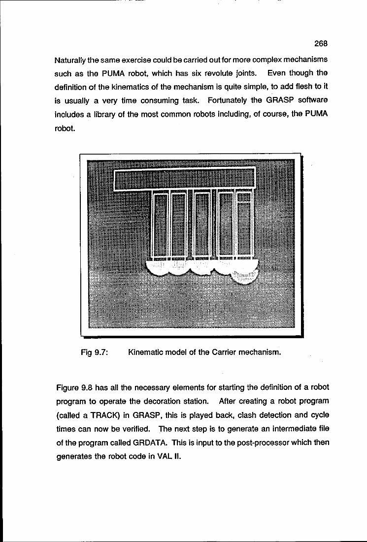
268
Naturally the same exercise could be carried out for more complex mechanisms
such as the PUMA robot, which has six revolute joints. Even though the
definition of the kinematics of the mechanism is quite simple, to add flesh to it
is usually a very time consuming task. Fortunately the GRASP software
includes a library of the most common robots including, of course, the PUMA
robot.
Fig 9.7: Kinematic model of the Carrier mechanism.
Figure 9.8 has all the necessary elements for starting the definition of a robot
program to operate the decoration station. After creating a robot program
(called a TRACK) in GRASP, this is played back, clash detection and cycle
times can now be verified. The next step is to generate an intermediate file
of the program called GRDATA. This is input to the post-processor which then
generates the robot code in VAL 11.
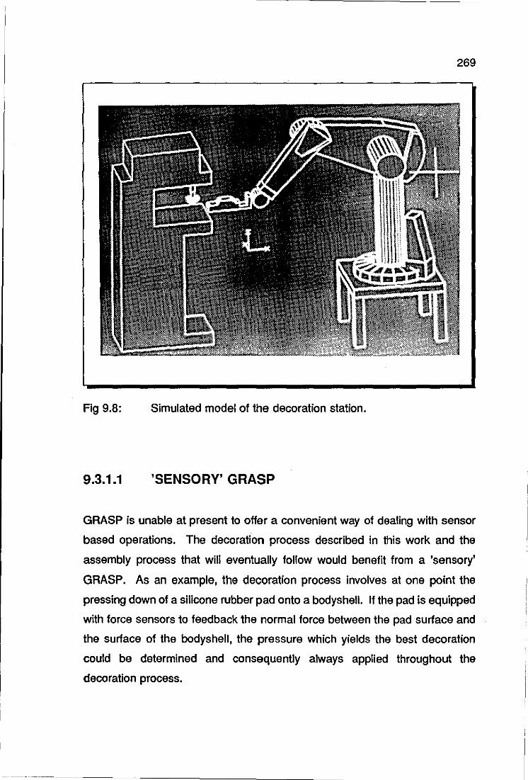
269
Fig 9.8: Simulated model of the decoration station.
9.3.1.1 'SENSORY' GRASP
GRASP is unable at present to offer a convenient way of dealing with sensor
based operations. The decoration process described in this work and the
assembly process that will eventually follow would benefit from a 'sensory'
GRASP. As an example, the decoration process involves at one point the
pressing down of a silicone rubber pad onto a bodyshell. If the pad is equipped
with force sensors to feedback the normal force between the pad surface and
the surface of the bodyshell, the pressure which yields the best decoration
could be determined and consequently always applied throughout the
decoration process.
270
Initial ideas are to develop software which will allow each piece of machinery
which is drawn on the screen by GRASP to carry with it some icon displaying
sensor data changing with time. For example, it is possible for GRASP to
display a gripper holding an object. The gripper/object pair can be viewed in
3D from any angle and with any scale facto ring. However GRASP cannot
display either the actual grip force or the demanded grip force. It is envisaged
that software will be developed so that this gripper/object picture will carry with
it some scale or dial face showing both the actual and the predicted grip force.
As the task proceeds these will change and this will be shown by an arrow or
dial needle moving in the simulated scene. This 'sensory' GRASP will be much
more user-friendly than the present system. Possible additions include forces,
processed image data, proximity sensor data for collision avoidance, output
from various poka-yoke devices and so on.
Assembly of scale models is the area of research that naturally follows on from
decoration. The benefits of a 'sensory' Grasp can be noticed more clearly in
assembly operations, where the Grasp software can 'learn' about correct
operations of the cell by monitoring its performance and storing the appropriate
data. Each sensor will transduce some quantity and will be able to store its
time store as a performance vector (or matrix for a multidimensional array
sensor). The performance vector database is learned from real life operation
via a direct link between the cell sensors and the Grasp software. The
performance vectors therefore reflect 'real' rather than calculated performance.
The database comprising these performance vectors 'attached' to each sensor
can be monitored and displayed during the simulation of the cell using Grasp.
This will provide the operator with a very powerful tool. For example, during
some insertion operation the operator may define a chamfer of certain
dimensions. The performance vector for the force sensor monitoring the
Insertion operation will be called up and processed to display the force history
during the insertion operation. If the operator decides that the force is
excessive at some pOint, he can define a different chamfer or a wider tolerance
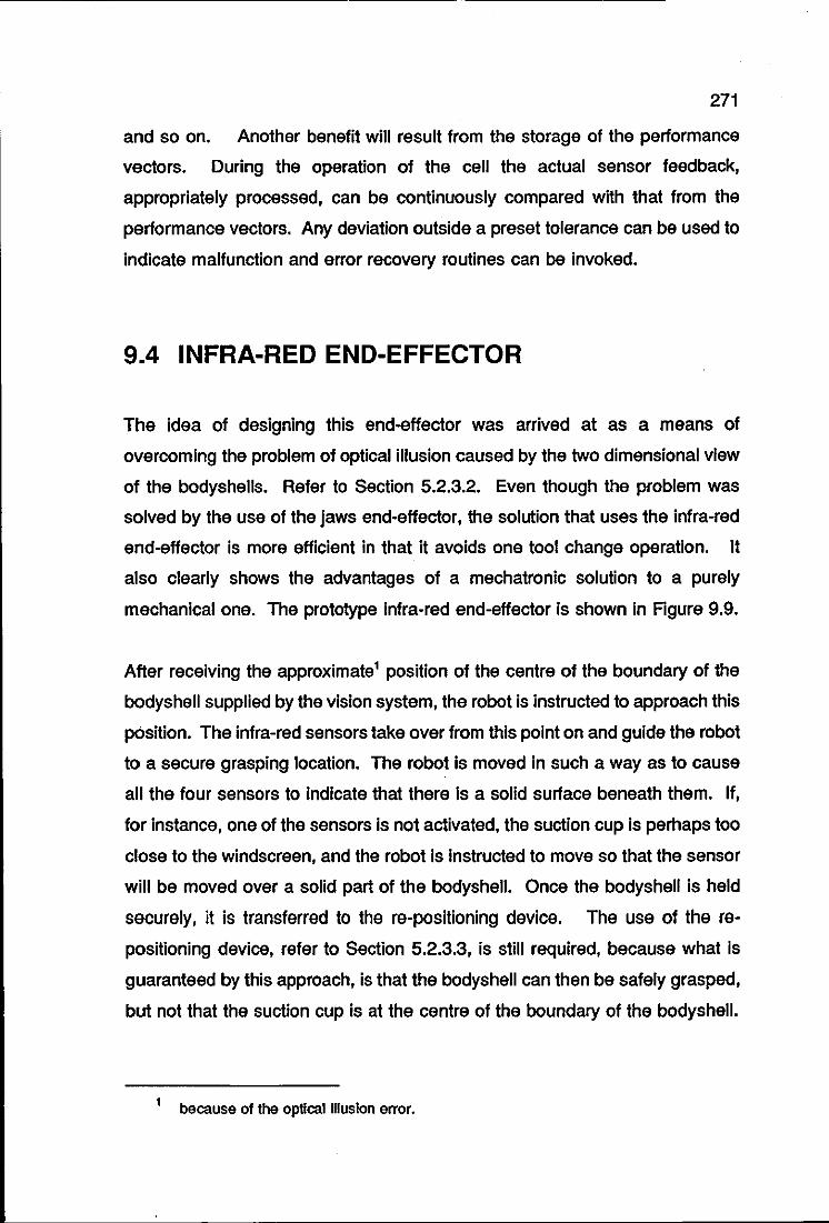
271
and so on. Another benefit will result from the storage of the performance
vectors. During the operation of the cell the actual sensor feedback,
appropriately processed, can be continuously compared with that from the
performance vectors. Any deviation outside a preset tolerance can be used to
indicate malfunction and error recovery routines can be invoked.
9.4 INFRA-RED END-EFFECTOR
The idea of designing this end-effector was arrived at as a means of
overcoming the problem of optical illusion caused by the two dimensional view
of the bodyshells. Refer to Section 5.2.3.2. Even though the problem was
solved by the use of the jaws end-effector, the solution that uses the infra-red
end-effector is more efficient in that it avoids one tool change operation. It
also clearly shows the advantages of a mechatronic solution to a purely
mechanical one. The prototype infra-red end-effector is shown in Agure 9.9.
After receiving the approximate1 pOSition of the centre of the boundary of the
bodyshell supplied by the vision system, the robot is instructed to approach this
pOSition. The infra-red sensors take over from this point on and guide the robot
to a secure grasping location. The robot is moved in such a way as to cause
all the four sensors to indicate that there is a solid surface beneath them. If,
for instance, one of the sensors is not activated, the suction cup is perhaps too
close to the windscreen, and the robot is instructed to move so that the sensor
will be moved over a solid part of the bodyshell. Once the bodyshell is held
securely, it is transferred to the re-positioning device. The use of the re
positioning device, refer to Section 5.2.3.3, is still required, because what is
guaranteed by this approach, is that the bodyshell can then be safely grasped,
but not that the suction cup is at the centre of the boundary of the bodyshell.
1 because of the optical Illusion error.
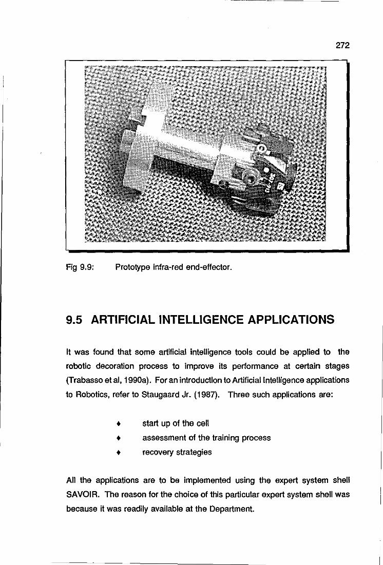
272
Fig 9.9: Prototype infra-red end-effector.
9.5 ARTIFICIAL INTELLIGENCE APPLICATIONS
It was found that some artificial intelligence tools could be applied to the
robotic decoration process to improve its performance at certain stages
(Trabasso et ai, 1990a). For an introduction to Artificial Intelligence applications
to Robotics, refer to Staugaard Jr. (1987). Three such applications are:
• start up of the cell
• assessment of the training process
• recovery strategies
All the applications are to be implemented using the expert system shell
SAVOIR. The reason for the choice of this particular expert system shell was
because it was readily available at the Department.
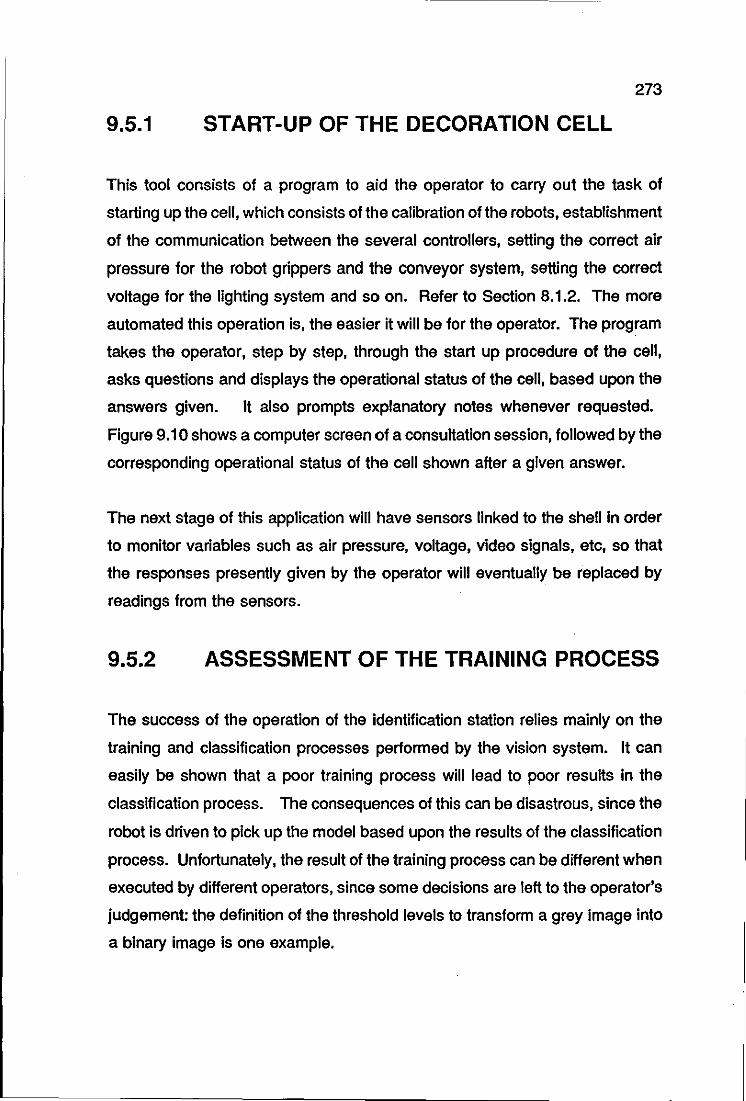
273
9.5.1 START-UP OF THE DECORATION CELL
This tool consists of a program to aid the operator to carry out the task of
starting up the cell, which consists of the calibration of the robots, establishment
of the communication between the several controllers, setting the correct air
pressure for the robot grippers and the conveyor system, setting the correct
voltage for the lighting system and so on. Refer to Section 8.1.2. The more
automated this operation is, the easier it will be for the operator. The program
takes the operator, step by step, through the start up procedure of the cell,
asks questions and displays the operational status of the cell, based upon the
answers given. It also prompts explanatory notes whenever requested.
Figure 9.10 shows a computer screen of a consultation session, followed by the
corresponding operational status of the cell shown after a given answer.
The next stage of this application will have sensors linked to the shell in order
to monitor variables such as air pressure, voltage, video signals, etc, so that
the responses presently given by the operator will eventually be replaced by
readings from the sensors.
9.5.2 ASSESSMENT OF THE TRAINING PROCESS
The success of the operation of the identification station relies mainly on the
training and classification processes performed by the vision system. It can
easily be shown that a poor training process will lead to poor results in the
classification process. The consequences of this can be disastrous, since the
robot is driven to pick up the model based upon the results of the classification
process. Unfortunately, the result of the training process can be different when
executed by different operators, since some decisions are left to the operator's
judgement: the definition of the threshold levels to transform a grey image into
a binary image is one example.
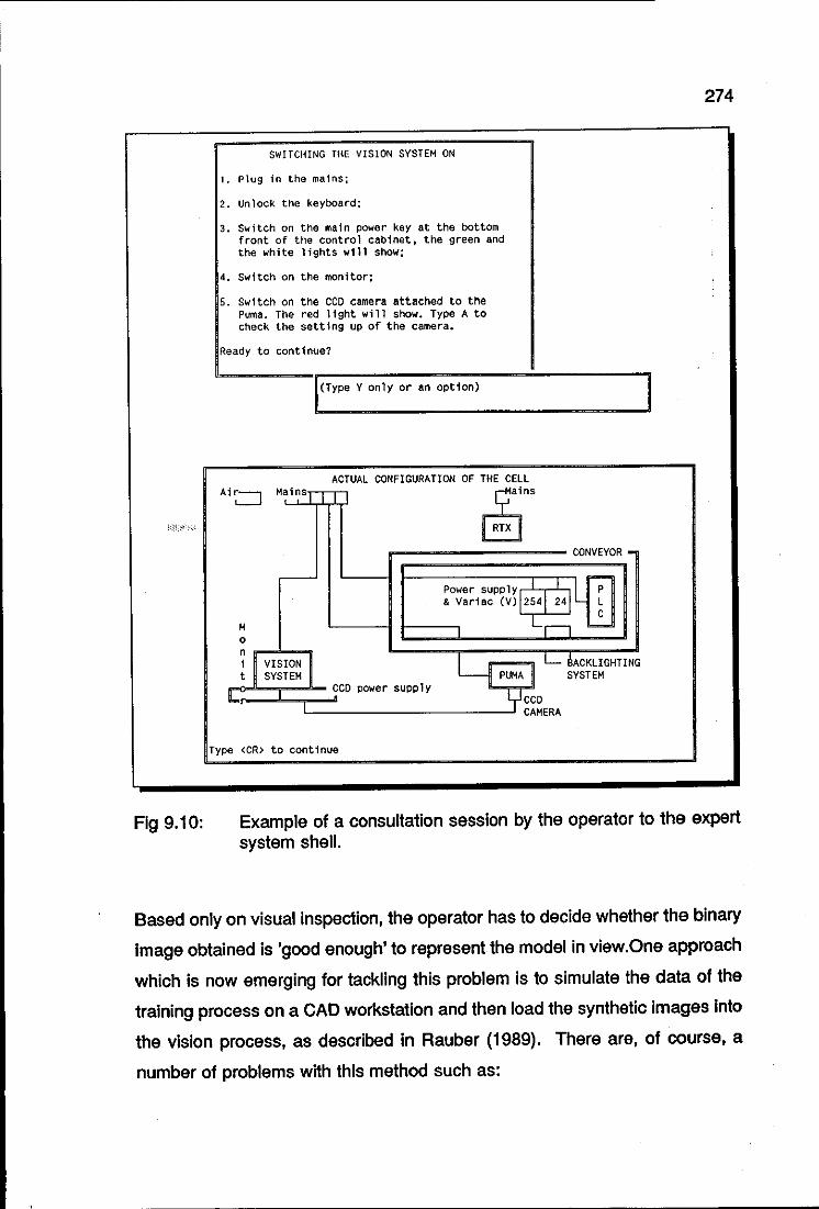
i<,~ :" ,,'
Fig 9.10:
274
SWITCHING THE VISION SYSTEM ON
1. Plug 1n the mains;
2. Unlock the keyboard;
3. Switch on the main power key at the bottom front of the control cabinet, the green and the white lights will show;
4. Switch on the monitor;
5. Switch on the CCO camera attached to the Puma. The red l1ght will show. Type A to check the setting up of the camera.
Ready to continue?
I(Type Y only or an option) I ACTUAL CONFIGURATION OF THE CELL
Ai8 MainsTTn ~ns RTX
CONVEYOR -
r-- ;-Power supply 1 L p & Vari ac (V) 12541 2~ L
C M L" b.-0 n i1 VISION I ~ 11 L-- BACKLIGHTING t SYSTEM PUMA SYSTEM
eco power supply ycco
I CAMERA
Type <eR> to continue
Example of a consultation session by the operator to the expert system shell.
Based only on visual inspection, the operator has to decide whether the binary
image obtained is 'good enough' to represent the model in view.One approach
which is now emerging for tackling this problem is to simulate the data of the
training process on a CAD workstation and then load the synthetic images into
the vision process, as described in Rauber (1989). There are, of course, a
number of problems with this method such as:
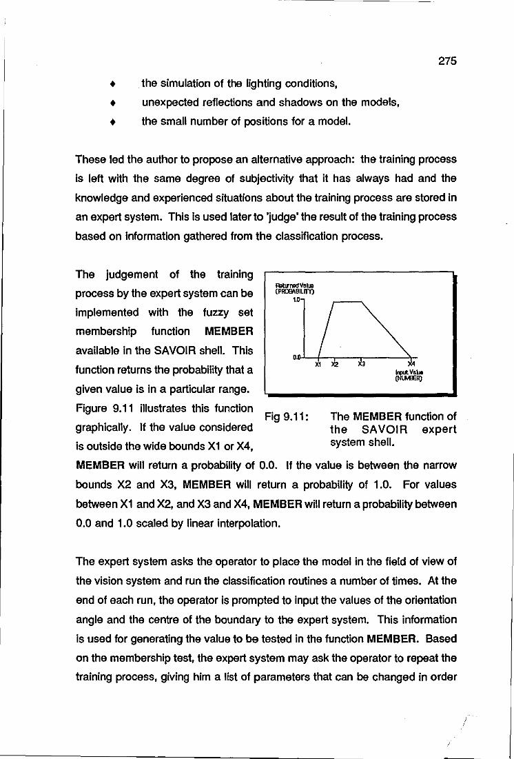
275
• . the simulation of the lighting conditions,
• unexpected reflections and shadows on the models,
• the small number of positions for a model.
These led the author to propose an alternative approach: the training process
is left with the same degree of subjectivity that it has always had and the
knowledge and experienced situations about the training process are stored in
an expert system. This Is used later to 'judge' the result of the training process
based on Information gathered from the classification process.
The judgement of the training
process by the expert system can be
implemented with the fuzzy set
membership function MEMBER
available in the SAVOIR shell. This
function returns the probability that a
Ratlr09d Villi» (PRlJElt,BLIIY)
1.0-
given value is in a particular range.
Figure 9.11 illustrates this function Fig 9.11:
graphically. If the value considered
is outside the wide bounds X1 or X4,
The MEMBER function of the SAVOIR expert system shell.
MEMBER will return a probability of 0.0. If the value is between the narrow
bounds X2 and X3, MEMBER will return a probability of 1.0. For values
between X1 and X2, and X3 and X4, MEMBER will return a probability between
0.0 and 1.0 scaled by linear interpolation.
The expert system asks the operator to place the model in the field of view of
the vision system and run the classification routines a number of times. At the
end of each run, the operator is prompted to input the values of the orientation
angle and the centre of the boundary to the expert system. This information
is used for generating the value to be tested in the function MEMBER. Based
on the membership test, the expert system may ask the operator to repeat the
training process, giving him a list of parameters that can be changed in order

276
to improve the result. Various important aspects and experienced situations
of the training process can be built into the model in the expert system. For
instance, the program can detect whether the camera is working at its
saturation level, based again on simple tests carried out by the operator. All
possible correction actions can be listed. In a sense, this approach is an
enhancement of the training assessment discussed in Section 7.2.2.2. The ,
approach has yet to be implemented and tested.
9.5.3 RECOVERY STRATEGIES
As mentioned in Section 8.2.4, the deviation sensors feed the recovery program
which keeps the knowledge about recovery actions through production rules.
The recovery actions are currently split into the various programs of the
decoration cell. For instance, the recovery action of the loading station is part
of the PLC program which controls the conveyor system. The recovery action
for obstacle collision for the PUMA robot is part of the program which controls
the tool changer mechanism and so on.
The ideal foreseen scenario is to have all the outputs of the deviation sensors
being fed into a single program. There is no better place for such a program
than an expert system shell which has the right structure for keeping the
recovery actions through production rules. A particular input from the sensors
would trigger a corresponding recovery action. This application has yet to be
implemented.
277
CONCLUSION
This chapter has presented important topics for further research. Regarding
the Hornby Hobbies & Loughborough University project, the most important
topic is the matrix-on-belt approach to decoration. The author foresees this
approach being implemented even without the use of the PUMA robot. To this
end an efficient way of transferring the bodyshells from one printing machine
to the other has to be found. This operation also demands changes in the
bodyshells orientation.
The mechatronic tool ch anger and the infra-red end-effector have applications
beyond scale model decoration. It is believed that the novel tool changer has
a place in the robotic market: the tool changes can be carried out very speedily,
given the simplicity of the locking-unlocking principles, the electric contacts are
not subject to wear. The infra-red end-effector and the re-positioning device
make an alternative and cheaper option to be considered when three
dimensional objects have to be analysed by a two dimensional vision system.
One can argue that the expert system applications presented could have been
implemented using any high level language such as, for instance, Pascal. This
artificial intelligence tool was proposed because it has readily available suitable
structures to be used, for instance, production rules for the recovery actions
and membership functions for the assessment of the training process. It also
has graphic facilities and is very user friendly.

278
CONCLUSION
279
The results of this work can be analysed through two different view points:
narrow and broad. In the narrow view are the contributions made to the scale
model decoration process and in the broad view are the contributions made to
Mechatronics.
CONTRIBUTIONS TO THE SCALE MODEL
DECORATION PROCESS
The design requirements of the decoration cell stated in Section 4.2 were
summarised as follows:
Design a cell which is capable of decorating and inspecting any
bodyshell manufactured by Homby Hobbies Ltd., using the pad
printing technique in a flow operation at a production rate of 60
bodyshells per hour.
The first design requirement to be attained was the embedded flexibility of the
decoration process. A detailed analysis of the cell flexibility was presented in
Section 8.1.3. It was pointed out that the pad principle of decoration turned out
to be the main constraint to the overall flexibility of the decoration cell. All but
the decoration station can be easily and quickly re-programmed to execute a
new livery. No special jigs were used so that much of the bulk of the cell
hardware remains unchanged when a changeover occurs. The majority of the
modifications are related to software.
It is believed that this flexibility requirement was fully met. It is now emerging
as the future of pad printing using the sealed ink system described in Section
3.1.1. If Hornby Hobbies Ltd. eventually switch to this technology then the
flexibility of the decoration cell would become more realistic.
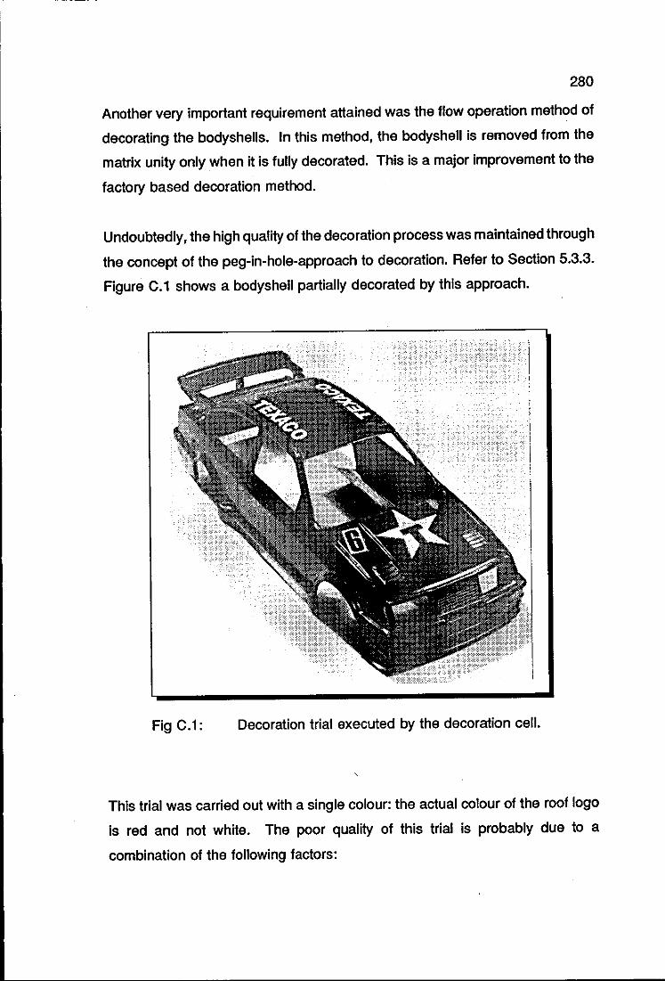
280
Another very important requirement attained was the flow operation method of
decorating the bodyshells. In this method, the bodyshell is removed from the
matrix unity only when it is fully decorated. This is a major improvement to the
factory based decoration method.
Undoubtedly, the high quality of the decoration process was maintained through
the concept of the peg-in-hole-approach to decoration. Refer to Section 5.3.3.
Figure C.1 shows a bodyshell partially decorated by this approach.
Fig C.1: Decoration trial executed by the decoration cell.
This trial was carried out with a single colour: the actual colour of the roof logo
is red and not white. The poor quality of this trial is probably due to a
combination of the following factors:
281
o lack of experience with the ink/printing technique,
o 'dirty' bodyshells, which have been handled many times,
o poor cliche.
It has been stated in Section 5.3.2 that some kind of active restring device was
necessary to hold the bodyshell onto the matrix. Because of the shape of the
model on which the tests were carried out, this proved to be unnecessary. It
has to be stressed, however, that some models do require such a device.
It was only possible to estimate the production rate of the decoration cell
because only one printing machine was actually linked to the cell. This was
within the value specified. However, this can be dramatically improved by the
matrix-on-belt approach to decoration which still keeps the basic idea of the
peg-in-a-hole but explores the full potential of the PUMA robot.
Another important contribution is the quality control aspect which was added to
the decoration process: it is no longer subjective and inconsistent.
It is important to note that the decoration cell was designed in such a way that
it could be fully integrated into the factory. Refer to Figure 8.1. The injection
moulding machines are at one end of the cell and the assembly lines at the
other, ready to carry on the next operations with the bodyshells. If eventually
assembly is to be automated, the first problem has already been solved by the
unloading station of the decoration cell: the determination of the position of the
bodyshells.
It is believed that all the initial design requirements of the decoration process
were met. Naturally, it is not expected to have the decoration cell simply
moved from the laboratory to the factory. This was stressed right from the
beginning of this work. However the author believes that much of the work
developed here can be readily incorporated into an automated decoration
process if Hornby Hobbies Ltd. eventually choose this route. If this is the
282
case, then the author strongly recommends that open ink well printing machines
currently used are replaced with sealed ink machines. This is because the
latter do not require frequent action by the operators.
CONTRIBUTIONS TO MECHATRONICS
The essence of the work carried out was heavily practical: the final result
obtained was a working unit. Consequently, it is not expected to have a major
theoretical contribution yielding from this work.
Nevertheless, the author believes that the Mechatronics Design Methodology
proposed in Chapter 4 could be used as an initial guide for those interested
In Mechatronics design. The main claim associated with that methodology is
that it has been successfully and extensively used in the design of the
decoration cell.
Some people believe that there is no need for a discipline such as
Mechatronics. They argue that Mechatronics design has already been
practised for a number of years, often without the practitioners being conscious
of the name. One expects to find different results when the Mechatronics
philosophy is applied by accident to product design from when it is intentionally
used.
It Is rather difficult to visualise the final configuration of the decoration cell as
a whole if it were designed by other techniques rather than the Mechatronics
approach. However, it is not difficult to carry out this exercise with some
components of the cell. For example, after facing the problems with reflections
when identifying the bodyshells, the solution of locating the bodyshells using
positioning jigs seemed to be viable even though it would be at the expense of
flexibility. Opposing this purely mechanical solution was the side-lighting
system, which is essentially an integrated electrical-mechanical solution,
283
overcame the problem and maintained the flexibility of the cell. Another
example is the re-positioning device in which a simple mechanical solution
solved the problem of optical illusion error that might have been solved in a
very complex manner if the designer had only pursued the software route.
These are only samples of simple, cheap and efficient devices operating within
the cell whose conception was arrived at as a direct result of the Mechatronics
approach to design. Thus the decoration cell is a rather good example of a
mechatronic product. The key element of Mechatronics, integration, can be
readily and graphically noticed when the cell is operating. Furthermore,
following its design and analysing its operation one will conclude that
Mechatronics really needs to be thought of as technology which one has to
aware of in order to design a low cost, simple and versatile product.
As a final and personal remark, the author acknowledges that after working for
some time within the Mechatronics framework, he acquired the Mechatronics
way of looking at problems, I.e. how can he allocate the functional requirements
of this component between the mechanical, electronic and computing science
environments? This made design an enjoyable activity, but he would not dare
to add 'enjoyable activity' as yet another attribute of Mechatronics Design. Or
would he?

284
REFERENCES

285
ALGER, R. M. and HAYES, C. V. (1964). Creative Synthesis in Design. Prentice Hall, Englewood Cliffs, NJ.
ANDREASEN, M. M. and HEIN, L. (1987). Integrated Product Development. IFS Publications/Springer-Verlag, Berlin.
ASIMOW, M. (1962). Introduction to Design. Prentice-Hall, Englewood Cliffs, NJ.
BLACK, I. and MURRA Y, J. L. (1989). Concept Embodiment: a Methodological Basis for Effective Computer Aided Design. Proceedings of the IMechE Conference on Engineering Design, Harrogate, UK, Vol. 2, pp 929-946 ..
BOOTHROYD, G. (1987). Design for Assembly - The key to Design for Manufacture. The International Journal of Manufacturing Technology, Vol. 2, pp 3-11.
BRADLEY, D. A. and DAWSON, D. (1990). Achieving Integration Engineering Design Education: The Role of Mechatronics. Mechatronic Systems Engineering, Vol. 1, Kluwer Academic Publishers, the Netherlands, pp 19-29.
BREMMERMAN, H. J. (1983). Optimization through Evolution and Recombination. Spartan Books, Chicago.
BUHL, H. R. (1962). Creative Engineering Design. Iowa State University Press, Ames.
BUUR, J. (1989). A Framework for Mechatronics Design Methodology. Proceedings of the IMechE Conference on Engineering Design, Harrogate, UK, Vol. 1, pp 507-518 ..
BUUR, J. (1990). Mechatronics in Japan - strategies and practice in product development. Proceedings of the IMechE Conference on Mechatronics: Designing Intelligent Machines, Cambridge, UK, pp 131-136.
BYG SYSTEMS LTD. (1990). GRASP 3D Graphical Simulation. User's manual, Nottingham, UK.
CHAN, S. F. (1989). Advancement in Robot Programming with Specific Reference to Graphical Methods. Loughborough University of Technology, Department of Manufacturing Engineering, Loughborough, UK. (Ph.D. Thesis).
DAIZHONG, S. and FORGIE, R. J. (1989). Development of an Expert System Approach to an Engineering Design Procedure. Proceedings of the IMechE Conference on Engineering Design, Harrogate, UK, Vol. 2, pp 975-989.
DIETER, G. E. (1983). Engineering Design: a Materials and Processing Approach. McGraw-HiII, New York, NY, 1983.
286
DINSDALE, J. (1989). Mechatronics: The European Dimension. IMechE Seminar - What is Mechatronics, Loughborough, UK.
DOEBELlN, E. O. (1983). Measurement Systems: Application and Design. McGraw-HiII, New York, NY.
FASAL, J. (1965). Force Decisions for Value. Product Engineering, April 1965, pp 356-360.
FRENCH, M. J. (1989). Do We Really Need Mechatronics? IMechE SeminarWhat is Mechatronics, Loughborough, UK.
FRENCH, M. J. (1990). The Partition of Functions in Mechatronic Design. Proceedings of the IMechE Conference on Mechatronics: Designing Intelligent Machines, Cambridge, UK, pp 209-211.
FU, K. S., GONZALES, R C., LEE, C. S. G. (1987). Robotics: Control, Sensing, Vision and Intelligence. McGraw-HiII, Singapore.
GARRAT, J. (1989). Metrology Instrumentation IMechE Seminar - What is Mechatronics, Loughborough, UK.
GLEGG, G. L. (1960). Design of Design. Cambridge University Press, New York, NY.
GROB, H. (1987). Pad Printing Impresses the Plastic Industry. Plastics Engineering, pp 39-41, June 1987.
GROOVER, M. P., WEISS, M., NAG EL, RN., ODREY, N.G. (1988). Industrial Robotics: Technology, Programming and Applications, McGraw-HiII, New York, NY.
HANSON, M. (1990). Integration of Advanced Microcomputer System Design In Mechanical Engineering Education. Proceedings of the IMechE Conference on Mechatronics: Designing Intelligent Machines, Cambridge, UK, pp 261-270.
HARRISBERGER, L. (1966). Engineermanship: a Philosophy of Design. Brooks/Cole, Belmont, CA.
HEWIT, J. R (1989). Mechatronics & Innovation IMechE Seminar - What is Mechatronics, Loughborough, UK.
HEWIT, J. Rand FAWCETT, J. N. (1989). Mechatronic Design of a Belt Tensioning System. Proceedings of the Conference on Mechatronics in Products and Manufacturing, Lancaster, UK.
HUNT, V.D. (1988). Mechatronics: Japan's Newest Threat. Chapman and Hall, New York, NY.
287
HURST, K. S. and JAMES, R. D. (1990). Feasibility Study of an Automated Materials Testing Facility for British Steel of Scunthorpe. Proceedings of the IMechE Conference on Mechatronics: Designing Intelligent Machines, Cambridge, UK, pp 83-90.
INTELLIGENT SYSTEMS INTERNATIONAL. (1987). The Savoir Expert System Shell: Programmers Guide. Surrey, UK.
JOYCE-lOEBL. (1987). Magiscan: Pascal Programmer's Guide. Gateshead, Newcastle-upon-Tyne, UK.
JOYCE-lOEBL. (1985). Image Analysis: Principles and Practise. Gateshead, Newcastle-upon-Tyne, UK.
KAJITANI, M. (1989). A concept of Mechatronics. Techno Japan Vol. 22, n. 10, pp 13-16.
KAYE, G. W. C. (1973). Tables of Physical and Chemical Constants. pp 91, Van Nostrand Reinhold, New York, NY.
KEYWORTH, V. E. (1989). Mechatronics Awareness and the Development of Hands-on Training Equipment to the CIM Environment. Proceedings of the Conference on Mechatronics in Products and Manufacturing. lancaster, UK.
lEHN, B. (1983). The Pad-Printing Process. Proceedings of the Conference on Transfer lettering-Printing, Brugg-Windisch, Switzerland, pp 7-11.
MITSUBISHI ELECTRIC CO. (1987). Melsec Ft Series Mitsubishi Programmable Controller: Programming Manual, High Function Version, Tokyo, Japan.
OSTROTSKY, B. (1977). Design, Planning and Development Methodology. Prentice-Hall, Englewood Cliffs, NJ.
PRESTON, M. E., KING, T. G., VITOlS, R., WRAY, G. R., and MURPHY, B. J. (1990). A Mechatronic System for Knitted Fabric Handling. Proceedings of the IMechE Conference on Mechatronics: Designing Intelligent Machines, Cambridge, UK, pp 17-22.
PRESTON, M. E., KING, T. G., WRA Y, G. R., VITOlS, R., and MURPHY, B. J. M. (1989). Mechatronics Applied to the Manufacture of Knitted Garments. Proceedings of the Conference on Mechatronics in Products and Manufacturing, Lancaster, UK.
RAUBER, T. W. (1989). Generating Synthetic Images Using PADL-2. New University of Lisbon, Department of Robotics, Lisbon, Portugal. (TeChnical Report GR RT-PS-10-89).
288
ROACH, S. (1989). Design of an Automatic Tool Changer for the PUMA Robot. Loughborough University of Technology, Department of Mechanical Engineering, Loughborough, UK. (Final year project report).
ROGERS, M. (1979). Pad Printing Equipment: What It Does; Where To Buy It. Plastics Technology, pp 73-77, September 1979.
RUOCCO, S. R. (1987). Robot Sensors and Transducers, Open University Press, Milton Keynes, UK.
SALMINEN, V. and VERHO, A. J. (1989). Multi-Disciplinary Design Problem in Mechatronics and Some Suggestions to Its Methodical Solution in Conceptual Design Phase. Proceedings of the IMechE Conference on Engineering Design, Harrogate, UK, Vol. 1, pp 533-554.
SATAS, D. (1986). Plastics Finishing and Decoration. Van Nostrand Reinhold Company Inc., New York, NY.
SEYER, M. D. (1984). RS-232 Made Easy: Connecting Computers, Printers, Terminals and Modems. Prentice-Hall, Inc., NJ.
SHIGLEY, J. E. (1986). Mechanical Engineering Design. McGraw-HiII, New York, NY.
SHINGO, S. (1986). Zero Quality Control: Source Inspection and the PokaYoke System. Productivity Press, Cambridge, MA.
STAUFFER, L. A. (1989). Commonality of Design in Diverse Domains. Proceedings of the IMechE Conference on Engineering Design, Harrogate, Vol. 1, pp 447-459.
STAUGAARD JR., A. (1987). Robotics and AI: an Introduction to Applied Machine Intelligence. Prentice-HalJ Inc., Englewood Cliffs, NJ.
STINTON, B. G. T. (1974). Printing on Complex Surfaces. Proceedings of the Conference on Finishing. Decoration and Assembly of Plastics Mouldings, Coventry, UK, paper n. 9.
SUH, N. P. (1990). The Principles of Design. Oxford University Press, Oxford, UK.
TAYLOR, G. T. (1990). The Mechatronics Curriculum for the Modern Engineer. Proceedings of the IMechE Conference on Mechatronics: Designing Intelligent Machines, Cambridge, UK, pp 271-279.
TEXAS INSTRUMENTS (1984). The TTL Data Book For Design Engineers. 2 Vol., European Edition.
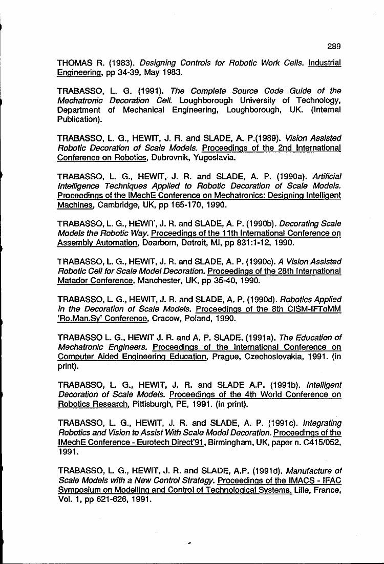
289
THOMAS R. (1983). Designing Controls for Robotic Work Cells. Industrial Engineering. pp 34-39, May 1983.
TRABASSO, L. G. (1991). The Complete Source Code Guide of the Mechatronic Decoration Cell. Loughborough University of Technology, Department of Mechanical Engineering, Loughborough, UK. (Internal Publication).
TRABASSO, L. G., HEWIT, J. R. and SLADE, A. P.(1989). Vision Assisted Robotic Decoration of Scale Models. Proceedings of the 2nd International Conference oh Robotics, Dubrovnik, Yugoslavia.
TRABASSO, L. G., HEWIT, J. R. and SLADE, A. P. (1990a). Artificial Intelligence Techniques Applied to Robotic Decoration of Scale Models. Proceedings of the IMechE Conference on Mechatronics: Designing Intelligent Machines, Cambridge, UK, pp 165-170, 1990.
TRABASSO, L. G., HEWIT, J. R. and SLADE, A. P. (1990b). Decorating Scale Models the Robotic Way. Proceedings of the 11th International Conference on Assembly Automation, Dearborn, Detroit, MI, pp 831 :1-12, 1990.
TRABASSO, L. G., HEWIT, J. R. and SLADE, A. P. (1990c). A Vision Assisted Robotic Cell for Scale Model Decoration. Proceedings of the 28th International Matador Conference, Manchester, UK, pp 35-40, 1990.
TRABASSO, L. G., HEWIT, J. R. and SLADE, A. P. (1990d). Robotics Applied in the Decoration of Scale Models. Proceedings of the 8th CISM-IFToMM 'Ro.Man.Sy' Conference, Cracow, Poland, 1990.
TRABASSO L. G., HEWIT J. R. and A. P. SLADE. (1991a). The Education of Mechatronic Engineers. Proceedings of the International Conference on Computer Aided Engineering Education, Prague, Czechoslovakia, 1991. (in print).
TRABASSO, L. G., HEWIT, J. R. and SLADE A.P. (1991b). Intelligent Decoration of Scale Models. Proceedings of the 4th World Conference on Robotics Research, Pittisburgh, PE, 1991. (in print).
TRABASSO, L. G., HEWIT, J. R. and SLADE, A. P. (1991c). Integrating Robotics and Vision to Assist With Scale Model Decoration. Proceedings of the IMechE Conference - Eurotech Direct'91, Birmingham, UK, paper n. C415/052, 1991.
TRABASSO, L. G., HEWIT, J. R. and SLADE, A.P. (1991d). Manufacture of Scale Models with a New Control Strategy. Proceedings of the IMACS - IFAC Symposium on Modelling and Control of Technological Systems. Lille, France, Vol. 1, pp 621-626, 1991.
290
TRABASSO, L. G., HEWIT, J. R. and SLADE, A. P. (1991e). Printing Scale Models Using Mechatronic Techniques. Mechatronics, Vol. 1, n. 1, pp 95-104, 1991.
TRABASSO, L. G., HEWIT, J. R. and SLADE A.P. (19911). Vision Assisted Robotics in the Decoration and assembly of scale models. Proceedings of the Euriscon - Imacs Conference, Corfu, Greece, 1991. (in print).
TRABASSO, L. G. and ZIELlNSKI, C. (1990). Semi-Automatic Calibration Procedure for the Vision-Robot Interface Applied to Scale Model Decoration. Robotica. (paper submitted 1990). .
TRAUERNICHT, J. O'RINDA. (1969). Printing and Decorating Plastics: What's New, What's Available. Plastics Technology. pp 41-51, September 1969.
VINCENT JO. (1989). Bear Necessities. CADCAM International, pp 6-7, December 1989.
WALDON, S. and MYSTEL; A. (1988). Multiresolutional Representation of Spatial Knowledge in Intelligence Control. Artificial Intelligence in Engineering: Robotics and Processes. Computational Mechanics Publications, Southampton, UK.
WARD, A.C. and SEERING, W. (1989). The Performance of a Mechanical Design Compiler. M.I.T., Artificial Intelligence Laboratory, Massachussets, MA. (Memo 1084).
WESTBROOK, M. H. (1989). Automotive Mechatronics. IMechE Seminar -What is Mechatronics, Loughborough, UK.
WIRTH, N. (1976). Algoritms + Data sctructures = Programs. Prentice Hall, Englewood Cliffs, NJ.
WOODSON, T. T. (1966). Introduction to Engineering Design. McGraw-HiII, New York, NY.
ZWICKY, F. (1948). The Morphological Method of Analysis and Construction. Interscience Publishers, New York, pp 461-470. (Courant Anniversary Volume).