
Mechatronics applied to scale model decoration · Mechatronics applied to scale model decoration...
178
•
Transcript of Mechatronics applied to scale model decoration · Mechatronics applied to scale model decoration...

Loughborough UniversityInstitutional Repository
Mechatronics applied toscale model decoration
This item was submitted to Loughborough University's Institutional Repositoryby the/an author.
Additional Information:
• A Masters Thesis. Submitted in partial fulfilment of the requirements forthe award of Master of Philosophy of Loughborough University.
Metadata Record: https://dspace.lboro.ac.uk/2134/25273
Publisher: c© Alan Peter Slade
Rights: This work is made available according to the conditions of the Cre-ative Commons Attribution-NonCommercial-NoDerivatives 4.0 International(CC BY-NC-ND 4.0) licence. Full details of this licence are available at:https://creativecommons.org/licenses/by-nc-nd/4.0/
Please cite the published version.

·.'
LOUGHBOROUGH UNIVERSITY OF TECHNOLOGY
LIBRARY
AUTHOR/FILING TITLE
~~~~~~~:~_~~~~~~~~~~~~~~~~~~~~~_~~~~~~~~~~~J ACCESSION/COPY NO.
«'to \ \:) \ ,,( ----------------- .--- .-- ---- --- ----- ------ - - - - - - --
VOL. NO. CLASS MARK
, JeJ:t,~.
: .J1JUN/91 ~ :,lO ~~'S.+ I SS Flfe E
ip-rCf<? roj'??
. ;
0401
111111 ,111111111111111111111
--------,----.. --~---------


MECHATRONICS APPLIED TO SCALE MODEL DECORATION
by
Alan Peter Slade
A Masters Thesis submitted in partial fulfilment of the award of
Master of Philosophy
of Loughborough University of Technology
Department of Mechanical Engineering Loughborough University of Technology
September 1993
© Alan Peter Slade, 1993


to Carol, my wife
Adam and Emily, my children for all the long nights that I
have been slaving over this keyboard.

ACKNOWLEDGEMENTS.
I wish to thank Professor Jim Hewit for giving me the opportunity to express my ideas on Robotics and Mechatronics. He has encouraged me, and his guidance has enabled me to write this thesis on a work close to my heart. He has always had time to listen to me and discuss ideas, however wild or esoteric, for this and other possible research and I feel that a lasting friendship has developed because of this.
I am also indebted to Luis Trabasso from the Instituto Technol6gico de Aeronautica, Sao Paulo, Brazil for his encouragement of me to write up my work whilst he was at Loughborough as a Research Student. We also wrote numerous papers and articles together and it was often decided on the toss of a coin who would go where to present them. We shared many things in common including a love of motor sport, and apparently I am also responsible for reviving a forgotten hobby of his.
Thanks also go to Dr. Cezary Zielin'ski, from the Warsaw University of Technology, for his suggestions and ideas and also TORBOL, the robot programming language he has developed, All I have to do now is learn Polish to understand it!
This project could not have been completed without the help ofBarry Ellis who made a lot of the mechanical components, We would discuss an idea and sketch out possible solutions and Barry would then go away and produce just what was required. Thank you very much indeed Barry, I wish also to thank Ken Topley and Vince Scothem for the photographic work,
I am grateful to the personnel at Homby Hobbies Limited for their assistance and help, especially to Keith Tyler and Derek Letley on the production side and Mike Waiters in the Design Office.
To Steve, who has spent many hours printing this for me, I say a heartfelt thanks, and sorry for all the hassle.
Finally, to my wife Carol, thank you for your support, love and understanding whilst I have been working on this,
------ --- --


CONTENTS
CHAPTER 1: INTRODUCTION TO THE PROJECT 1
1.1 SUMMARY 2
1.2 THE PRESENT FACTORY OPERATION 2
1.2.1 Spray Painting 3
1.2.2 Lining Out 4
1.2.3 Decoration 5
1.3 CONSTAlNTS IMPOSED ON THE PROJECT 7
1.4 PAD PRINTING 8
1.4.1 Origins of pad printing 8
1.4.2 Pad printing today 9
1.4.3 The Pad Printing Process 9
1.4.4 Pad Printing elements 10
1.4.4.1 Printing Plates 10
1.4.4.2 Pads 11
1.4.4.3 Inks 12
1.4.5 Applications 12
1.5 DEVELOPMENTS OF THE PAD PRINTING MACHINE 13
1.5.1 Current pad printing machines 13
1.5.2 Semi-sealed Systems 13
1.5.3 Closed Ink Systems 14
1.5.4 Fully Automated Systems 15
I
---- ----- --------,--~---- ------ --- --- -------- -.,..-- -- -- ----- ~ --

1.6 THE NEED FOR DECORATION 16
1.7 AN HISTORY OF SCALEXTRIC 18
l. 7.1 Future Plans 21
CHAPTER 2: CONFIGURING THE CELL 22
2.1 SUMMARY 23
2.2 THE FORESEEN PROBLEMS 23
2.2.1 Transporting the bodyshells 23
2.2.2 Handling the bodyshells 24
2.2.3 Identifying the bodyshells 26
2.2.4 Decorating the models 28
2.2.5 Inspecting the bodyshells 30
2.3 THE UNFORESEEN PROBLEMS 30
2.3.1 Conveying the models and lighting arrangements 30
2.3.2 Parallax error 33
2.3.3 Repositioning device 35
2.3.4
2.3.4.1
2.3.4.2
2.3.4.3
2.3.4.4
2.3.4.5
Accurate location at the printing machine and
inspection station
Fitment to the worktable
Adjustment of the angle for printing
Accurate placement
Interchangeability
Ease of use
2.4 HAND OVER FROM INSPECTION TO PACKING
35
36
36
37
38
38
39
I I

2.4.1 Co-operating robots 39
2.5 STACKING AND REMOVAL OF THE PALLETS 39
2.6 CYCLE TIME OF THE DECORATING CELL 40
2.6.1 Improvements to the decoration cell cycle time 41
CHAPTER 3: THE COMPONENT PARTS OF THE CELL. 43
3.1 SUMMARY 44
3.2 OVERVIEW OF THE PROOF-OF-CONCEPT CELL 44
3.2.1 The loading station 45
3.2.1.1 Mechanical adjustments 48
3.2.2 The identification station 49
3.2.2.1 Mechanical adjustment 50
3.2.2.2 Electrical adjustment 52
3.2.3 Information required from the identification station 53
3.2.3.1 Re-positioning device 55
3.2.4 Decoration station 56
3.2.4.1 Tool changer 56
3.2.4.2 Tampo print machine 57
3.2.5 The inspection station 58
3.2.6 The unloading station 59
3.2.6.1 The matrix/pallet concept 60
3.2.6.2 The 'H' shaped suction end-effector 61
3.3 THE TAMPO PRINTING MACHINE 63
3.3.1 Setting up 64
3.4 INTERFACING BETWEEN COMPONENTS 66
III

3.4.1 Loading station
3.4.2 Identification station
3.4.3 Decorating station
3.4.4 Inspection station
3.4.5 Unloading station
CHAPTER 4: THE SOFTWARE USED IN THE CELL
4.1 SUMMARY
4.2 SOFTWARE SYNTHESIS
4.2.1 Loading station
4.2.2 Identification station
4.2.3 Decoration station
4.2.4 Inspection station
4.2.5 Unloading station
4.3 THE JOYCE-LOEBL MAGISCAN VISION SYSTEM
4.3.1 Training process
4.3.2 Flowchart and data file output
4.3.3 Off-line assessment
4.3.4 Vision system PUMA robot calibration
4.4 GENERATION OF THE INSPECTION DATABASE
4.5 THE ON-LINE PROGRAMME - OWL
CHAPTER 5: THE ELECTRONIC AND ELECTRICAL
DESIGN OF THE CELL
66
66
67
67
68
69
70
71
71
73
74
76
77
79
81
82
83
83
85
90
92
IV
5.1 SUMMARY
5.2 THE RS-232C SERIAL LINK
5.3 - PROGRAMMABLE LOGIC CONTROLLER
5.3.1 Control of the workpiece carriers
around the conveyor system
93
93
96
97
5.4 ELECTRONIC SYNTHESIS OF THE FIVE STATIONS 99
5.4.1 Loading station 99
5.4.1.1
5.4.1.2
5.4.2
5.4.2.1
5.4.2.2
5.4.3
5.4.4
5.4.4.1
5.4.4.2
5.4.4.3
Sequential control of the loading mechanism
Monitoring the bodyshells
Identification station
Control of the station
CCD camera connection to the vision system
Decorating station
Inspection station
Camera connections
Interaction with the PUMA robot
Communication with the unloading station
5.5 UNLOADING STATION
5.5.1
5.5.2
Interaction between the PUMA and RTX robots
Control of the suction cups
99
101
103
104
104
106
109
109
109
110
110
liD
110
CHAPTER 6: THE OPERATION OF THE CELL 112
6.1 SUMMARY 113
6.2 OVERVIEW OF THE OPERATION OF THE CELL 113
v
----_._------------------

6.2.1 Work cycle
6.3 OPERATION OF THE CELL
6.3.1 Start up procedure
6.3.2 Operator interface
6.4 CONTROL OF THE CELL
6.4.1 Recovery strategies
6.5 FLEXIBILITY OF THE CELL
6.5.1 Modular decoration station
CHAPTER 7: AREAS FOR FURTHER RESEARCH
BALANCED CONFIGURATION DESIGN
APPRIMA - THE NEXT GENERATION OF
PAD PRINTING MACHINE
7.1 SUMMARY
7.2 POSSIBLE IMPROVEMENTS TO
THE PRINTING METHOD
7.2.1 The PAINTER approach
7.2.2 The peg-in-a-hole approach
7.2.3 The revised peg-in-a-hole approach
7.2.4 Improvements to the revised peg-in-a-hole approach
7.2.5 The matrix-on-belt approach
7.2.6 Other modifications to the printing machine
7.3 OTHER PRINTING TECHNOLOGIES
--------- - - ----~--
113
liS
liS
118
119
119
123
124
125
126
126
126
128
130
132
132
135
135
VI
i
--I

7.3.1 Ink Jet Printing
7.3.2 Transfer printing
7.4 MECHATRONIC TOOL CHANGER
7.4.1 The locking and unlocking principle
7.4.2 Pneumatic and electrical ports
7.5 SINGLE AXIS FORCE-ACCELERATION ADAPTOR
7.6 BALANCED CONFIGURATION DESIGN
7.7 ARTIFICIAL INTELLIGENCE APPLICATIONS
7.7.1 Start up of the decoration cell
7.7.2 assesment of the training process
7.7.3 Recovery strategies
7.8 APPRIMA - THE NEXT GENERATION OF
PAD PRINTING MACHINE
CHAPTER 8: CONCLUSION
8.1 SUMMARY
8.2 CONTRIBUTION TO SCALE MODEL DECORATION
AND PAD PRINTING
8.3 CONTRIBUTION TO MECHATRONICS
135
136
136
137
138
138
140
141
142
142
143
144
148
149
149
151
VII

LIST OF FIGURES
1.1 Using a spray mask 3
1.2 Lining out 4
1.3 The present factory operation 5
1.4 Decorating three models at once 6
1.5 The principle of Pad Printing 9
1.6 Pad shapes 11
1.7 Pad Printing Machine 13
1.8 Semi-sealed ink system 14
1.9 Closed Ink System 14
1.10 Automated print system 15
1.11 The improvement in decoration quality 17
1.12 The importance of decoration in the
scale model industry 17
2.1 Print matrix used in the decoration operation 25
2.2 The venturi principle 26
2.3 Examples of complex logos 27
2.4 The various orientations adopted by a bodyshell during decoration 29
2.5 Sidelighting at the identification station 33
2.6a) without sidelighting 34
2.6b) with sidelighting 34
2.7 The optical Illusion phenomenon caused by lack of depth infonnation 35
2.8 Using a 2-D representation of the bodyshells 35
2.9 The sensors around the vacuum cup 36
2.10 The repositioning device 37
2.11 The arrangement of the pegs and holes 38
2.12 Co-operating robots 40
2.13 Possible solution to the conveyor approach 42
VII I
_____ ~___ I
-- - - - ---- -- --- ---I

3.1 The Proof-of-Concept Cell 44
3.2 Principle of operation of the loading station 45
3.3 Side view of the loading station 48
3.4 Front view of the loading station showing
the adjustment slots for the chute. 49
3.5 Light distribution through the perspex block 50
3.6 Apparatus used for determining the total reflection angle
of the perspex block 51
3.7 Perspex block lit by a 5 milliwattHelium Neon laser at 0° (a) and 6° (b) 51
3.8 Angular adjustment of the side-lighting mechanism 52
3.9 The principle of operation ofthe re-positioning device 54
3.10 The inclination angles of the re-positioning device 55
3.11 The original tool changer 56
3.12 The Mechatronic tool changer 57
3.13 The inspection station 58
3.14 The component parts of a pallet 60
3.15 An assembled pallet 61
3.16 The 'H' section end-effector used on the RTX robot 62
3.17 The two actions performed by the 'H' shaped end-effector 63
3.18 Fitting the cliche onto the die-plate 64
3.19 The component parts of a Tampo Printing Machine 65
4.1 PLC input/output allotment at the loading station 71
4.2 Part of the PLC mnemonic code showing the routine
for the loading station 72
4.3 Structure of the off-line programme of the identification station 74
4.4 The VAL II code ofTUCANO 75
4.5 The VAL II code ofPRINT.TAMPO 75
4.6 The PUFFIN source code 78
4.7 An example of the palletising code 79
4.8 Typical structure of a Pascal programme using MAGISCAN units 81
4.9 Typical data file structure 82
4.10 Flowchart of the training process 84
4.11 The calibration marks on the workpiece carriers 85
I X

4.12 Typical image at the inspection station 86
4.13 Binary image ofthe bonnet highlighting light features 87
4.14 Computer screen of bonnet white features selection 88
4.15 Typical data structure of the inspection database 89
4.16 Flowchart of the interaction between OWL and EAGLE 91
5.1 Typical wiring connections between the PLC
and a proximity switch and stop gate 97
5.2 Schematic of the PLC connections in theproof-of-concept cell 98
5.3 Wiring of the PLC for controlling the loading station lOO
5.4 Sequential control of the loading station 101
5.5 The sensor fitted to the end of cylinder A 102
5.6 Principle of operation of the reflective opto-switch 102
5.7 Circuit used to boost the sensitivity of the reflective opto-switch 103
5.8 Wiring at the identification station 104
5.9 Sequential-control ofthe identification station 105
5.10 The CCD camera connections and control settings 106
5.11 The wiring connections between the PUMA controller
and the printing machine 108
5.12 Wiring of the unloading station 111
6.1 Schematic layout of the proof-of-concept-cell 114
6.2 PUMA-vision system RS-232 check 117
6.3 Recovery action at the loading station 121
6.4 Recovery action at the decoration station 122
7.1 Schematic of the PAINTER approach 127
7.2 Schematic of the peg-in-a-hole approach 129
7.3 The revised peg-in-a-hole approach 130
7.4 Modified peg-in-a-hole base unit 131
7.5 The indexing matrix principle 132
7.6 The principle of operation of the matrix-on-belt approach 133
7.7 The model of the prototype matrix-on-belt approach 134
7.8 The Mechatronic tool changer 136
X
7.9 The passive and active locking mechanisms of
the mechatronic tool changer 137
7.10 The Force/Acceleration adaptor undergoing trials 138
7.11 The graphs of force and acceleration for the assembly
of an axle into a chassis 139
7.12 Single axis force-acceleration adaptor 139
7:13 Balanced Configuration Design experimental unit 141
7.14 Example of a consultation session by the operator during
the start up of the decoration cell 142
7.15 A schematic of APPRIMA 146
8.1 The first Mechatronically decorated bodyshell ISO
X I

4.1
5.1
5.2
5.3
LIST OF TABLES
The various high level languages used in the proof-of-concept cell
The most popular pins implemented in an RS-232C serial link
The minimum configuration of an RS-232C serial link
The printing machine switches controlled by
the PUMA controller
70
95
95
108
6.1 Air supply pressure to the component parts of the proof-of-concept cell 116
7.1 The comparison of the features incorporated in the
different designs of pad printing machines 145
X I I
CHAPTER 1:
INTRODUCTION TO THE PROJECT.
1

1 SUMMARY.
The European toy industry is very heavily dependent on manual labour and therefore vulnera
ble to Far Eastern competitors, who have the advantage of lower labour costs. Automation is
Europe's best hope of beating off the oriental challenge.
This project presents one of the first working attempts to this end, represented by a proof-of
concept cell designed and commissioned for investigating the many problems and possibilities
associated with the decoration of scale models of cars and trains.
The aim of the project is to replace a traditionally manual series of operations by flexible auto
mation to provide the base for higher productivity and a greater degree of responsiveness to
product change, leading to Just In Time Manufacture with reduced Work In Progress, while
still retaining the high quality traditionally associated with the product.
The co-operating industrial partner for the project is Homby Hobbies Limited. Before describ
ing the proof-of-concept cell, it would be instructional to the reader to briefly explain the present
factory based method and the constraints put on the project by Homby Hobbies Limited so that
the reasons for choices within the cell will be more readily understood.
Because this project centres around the present decoration operations at Homby Hobbies Lim
ited, and in particular pad printing, an overview of pad printing is included. This will give the
reader a background to the problems faced during the project.
The importance of decoration to the model industry is discussed in section 1.6.
To finish this opening chapter a brief history of Scalextric is also included, as it is felt this is
also necessary to gain further background to the project.
1.2 THE PRESENT FACTORY OPERATION.
The models (cars or trains) are moulded in the factory and are then manually inspected for
• flash' or flaws in the moulding and the passed bodyshells are then wrapped in tissue paper and
2

boxed for the fIrst time. Depending upon the particular model there are three possible decora
tion methods that can be applied to it.
• spray painting
• lining out
• pad printing.
1.2.1 Spray Painting.
Spray painting, also known as large area spray, is chosen if the bodysheU has a relatively large
Figure 1.1: Using a spray mask
3

well defined area of colour to be added. This has two sub divisions; either first they go into the
automatic spray booth for an all over spray to obtain the authentic colour (most of the locomo
tive models go through this step) or they are fitted into a spray mask and air brushed to colour
(Figure 1.1).
The main problem with this second technique is the cleaning of the spray mask. The operator
has to strip and thoroughly clean the mask unit frequently to avoid paint runs inside the mask
and hence onto the model. This obviously slows production down considerably, to no more
than 15 - 20 models an hour.
Spray painting is recognised as the area where the greatest cost savings can be made as possibly
80% of the paint is wasted in spray mist into the filters and overspray onto the mask. It is here
that some other printing technology, such as ink jet printing would have the largest impact,
given the present limitations of the technology.
1.2.2 Lining Out.
Figure 1.2: Lining Oul
4

A particularly expensive operation is that of applying thin lines to the bodyshells of locomo
tives and other rolling stock. This is necessary to pick out the hand rails, roof edges, guttering
and so on. This can only be done manually at present (although a robotic method has been
developed for this technique) since the parts are either recessed, in the case of the handrails, or
proud in the case of the roof edges.
The method used is for an operator to ink these lines in using a 'claw' or mapping pen (Figure
1.2). The open nature of the pen and the fact that very little ink can be carried in the pen means
that it is constantly having to be cleaned and filled. There is a high degree of concentration and
skill required even though the job is in itself relatively simple, and there is a six month training
period for these particular operatives. These factors combine to produce a low work through
put of around six to ten models an hour.
1.2.3 Decoration.
Decoration (Figure 1.3) is a particularly labour intensive operation requiring a large amount of
skilful handling on the part of the operator to achieve a perfect finish. The particular model
that trials are being conducted on, for example, has 19 operations and will be presented to 7
Figure 1.3: The present factory operation.
5

tampo print machines, all set up for 2 colour and some 3 colour printing. This is an average
number of operations, and as a flow-line operation is not utilised it takes around two to three
weeks to finish all the decorations on any particular model.
After each decoration cycle the models are manuaIly inspected and then wrapped in tissue
paper and boxed and stored ready for the next operation which could be further decoration. It
takes typicaIly two to three hours to set up each tampo print machine for each decoration/colour
change.
It can be seen that this method of operation has the foIlowing distinct stages (Figure 1.4):
INPUT 3 2 1 BUFFER
Figure 1.4: Decorating three models at once
a) Each model must be selected from a box and placed at the first printing position to have
the first decoration printed
b) It must then be removed and placed at the second to have the second decoration added
c) This operation is then repeated for the third printing position
d) FinaIly it is removed and placed onto a conveyor belt, where it is transferred to the in
spection and re-packing station
e) Even though a "wet-on-wet" printing process is utilised models are sometimes put in a
'buffer' between the first and second and the second and third printing positions.
6

1.3 CONSTRAINTS IMPOSED ON THE PROJECT.
At the start of the project certain conditions were laid down by the industrial partners regarding
the proof-of-concept cell. These were that it should:
a) fit into a 5 meter square floor area
b) be able to fully decorate a model
c) utilise the existing tampo print machines
d) be able to handle all current and future models
f) operate with the minimum of supervision
e) be able to decorate trains as well as cars
g) be capable of integration into any future automation.
It can be seen straight away that condition (c) is a severe limiting factor on the overall flexibil
ity of the cell and that this directly affects, and in a way conflicts with, condition (b), in so much
as six or seven machines are required to fully decorate a model. These two conditions have, in
fact, have determined the whole strategy of the project.
Conditions (d) and (e) are not as bad as they might at first seem in that even though the model
varies, the overall size for the various types of model is reasonably constant. Therefore a uni
versal handling tool should be all that is necessary.
Condition (a) will allow for the greatest flexibility for positioning in a factory environment,
although a seven machine set up will require far more floor space while (t) is understandable,
why have large scale automation if you still need a large staff to look after it? Condition (g) is
another hard condition to satisfy in that at present there is very little automation in the factory,
and there is no clear indication as to what will happen in the future. In this case all that can be
done is to provide some form of 'standard' input and output to the cell.
The standard input facility is taken to be a chute/conveyor system and palletisation is assumed
as the output from it. This choice was fairly arbitrary but would seem to be reasonable in view
of the overall aim of Homby Hobbies to automate as much as possible. Chute/conveyor sys
tems are in use in many industries as the means of moving differing sized objects around, and
once orientation and position have been obtained by carrying out one operation (decoration) it
7
is best not to lose it before the next operation (assembly). In the case of Hornby Hobbies it
would also save on tissue paper and boxes as well as the models would not need the constant
wrapping and packing after each pass through the decoration cycle.
1.4 PAD PRINTING.
1.4.1 Origins of pad printing.
Pad printing is basically an offset gravure printing method. The ink is applied in excess over an
engraved plate, a blade removes the excess, a soft rubber pad picks up the ink from the en
graved plate and transfers it to the surface to be printed.
The origins of the pad printing process are to be found in the European watch industry two
hundred years ago. The method was originally developed for use in the Swiss watch industry
for decorating watch faces. In those days the watch faces were hand painted with ornate de
signs.
One of the artists involved had the idea of making a positive engraving of his dial design in a
metal plate, filling it with ink, removing the excess and using a rubber pad to transfer it to the
clock face.
The main advantage of this new process was that by using a finely engraved plate (or cliche),
very fine detail could be achieved. The disadvantage was that the gelatine pad used had a very
short life as it was subject to heat changes and attack by ink. Normally the pads had to be
remoulded daily and kept cool overnight.
In Gennany the industrialist Wilfried Philip saw the potential in other sectors of industry where
complex surfaces and inaccessible print areas were constantly giving rise to problems. Al
though he greatly contributed to the automation of the process in general, his major contribu
tion was the solution of the problems associated with the gelatine pad. He invented a new
fonnula for the pad material based on a silicone rubber compound plasticised with silicone oils.
In 1968 he founded Tampoprint which produced the first automatic pad printing machine for
large scale industrial use. 8
---I

1.4.2 Pad printing today.
The pad printing process presently competes successfully with other printing techniques such
as screen printing, hot foil, offset printing and mask spraying in decorative applications espe
cially on non-uniform and curved surfaces.
Today as much as 90% of the decoration in the interior of a car is applied by pad printing and it
is still the principal printing technique used in the watch industry from where it had its origins.
Pad printing can impress characters onto a completely assembled plastic keyboard at one stroke;
it can print decorative designs directly onto compact discs; it can impart decorations on plastic
beverage closures at fast assembly-line rates.
Pad printing can be applied to flat, cylindrical
or odd shaped parts, using either one or more
colours. In multiple colour printing, the wet-on
wet technique is used to build up the decoration
between the different colour applications. These
are claimed to be its main advantages when
compared to the other printing processes.
1.4.3 The pad printing process.
The actual principle of printing has remained
unchanged since the first machines i.e. transfer
ring an image from the cliche to the product,
however a detailed description of the process
based on the actual machines is given below.
Refer to Figure 1.5.
(a)
I (b)
(c)
1 (d)
Figure 1.5: The principle of pad printing
(a) The spatula blade mechanism moves forward across the cliche drawing ink from the ink
well with the doctor blade clear of the cliche and the pad, in the raised position, is moving
forward at the same time. (b) The spatula is spreading ink over the cliche; the pad is now
printing from the previous cycle onto the product. (c) The pad returns to the raised position and
9
~- -----------~--

the mechanism travels back to the start position with the doctor blade now in the down position,
wiping the surplus ink from the cliche. Thus just the engraving is left with ink in it. The thinner
evaporates from the engraving and the surface becomes tacky. (d) The pad descends onto the
cliche and as it presses onto the engraving ink sticks to the pad. As the pad lifts, it takes not
only the tacky, adhering film, but also the more fluid ink underneath.
(a) The pad moves away from the cliche and onto the product. On its way the thinner from the
exposed surface of the ink on the bottom of the pad evaporates, and so this surface now be
comes tacky. (h) The printing surface executes a rolling motion over the product, expelling the
air between the pad and the object. As the pad is pressed down the film of ink sticks to the
object and separates from the pad as it is raised. And so the cycle repeats.
1.4.4 Pad printing elements.
There are three main elements to a pad printing machine:
• printing plates
• printing pads
• inks.
1.4.4.1 Printing plates.
Printing plates are made from various materials including hardened steel, steel foil, plastic and
copper. Steel plates are made from 0.4 to 1 centimetre thick hardened and ground or chrome
coated steel. They are used for precision work and long runs, typically up to 10 million impres
sions. Although mechanically engraved steel plates are used they are usually engraved by pho
to-etching. The average etch depth is 0.02 to 0.04 millimetres.
Steel foils, which are prepared in a similar manner to hard steel plates, have a shorter life span of
around 50,000 impressions.
Copper plates can be an inexpensive alternative for short runs. However, because copper is
softer than steel, it requires a deeper etch and as a result, makes the ink harder to control in
10

printing. It dries more slowly, tends to blur and ultimately does not produce such clear or
accurate images as steel plates.
Nylon or photopolymer plates are the best plates for short runs. These are produced from a
metal backing plate coated with a photosensitive layer which polymerises under the action of
light, and so becomes hard. The etching process is again similar to that for steel plates. Treated
carefully, these plates can produce up to 20,000 impressions.
1.4.4.2 Pads.
The pads are manufactured from silicone rubber plasticised with silicone oils. They are made
by pouring the formulated silicone compound into a mould and then left to cure. The cured pad
is then mounted onto a plywood block. The pad shape depends upon the surface to be printed.
Some of the several standard shapes are shown in Figure 1.6.
a
d
Figure 1.6: Pad shapes: a) doughnut, b) standard, c) wedge, d) ribbon.
Pad (a) is a doughnut pad used for printing dials which have a raised knob in the centre. Pad (b)
is used for printing simple surfaces, achieving a good roll-off effect, minimising the possibility
of air entrapment under the ink. Usually the pad is compressed during printing until the side
II
walls are almost vertical. For printing long narrow areas' pad (c) is the most appropriate,
whilst pad (d) is used for printing the bottom of a slot.
The largest possible pad must be used in order to keep distortion to a minimum. Pads are
available in four hardness levels and the hardest pad that can be used for a particular application
should be selected, because harder pads have a better ink release and are more durable.
1.4.4.3 Inks.
The choice of the ink is governed by the requirements the ink has to meet. These can be
abrasion resistance, solvent resistance, whether glossy or matt, weatherproofing and so on.
The viscosity of the ink is very important. If it is too viscous it might not be picked up by the
pad from the cliche, if it is too fluid the cohesion might not be high enough and the ink may not
be completely transferred from the pad. Because ink viscosity is so critical in the pad printing
process, some ink manufacturers have developed simple viscosity meters that can be used when
the printing machine is operating.
1.4.5 Applications.
The range of applications for pad printing is limited only by the size of the image. Because it
can be used on irregular surfaces and in wet-on-wet operations pad printing is widely accepted
for printing computer components and electrical appliances. Pad printing is also used for med
ical devices, automotive parts, glass frames and lenses, sporting goods, toys, watch and instru
ment dials, irregularly shaped containers, advertising specialities, cigarette lighters, pens and
many other products.
1. Typically 5 x 20 centimetres
12

1.5 DEVELOPMENTS OF THE PAD PRINTING MACHINE.
1.5.1 Cu"ent Pad Printing Machines.
A large variety of pad printing machines are currently avail
able, ranging from small hand operated models to huge hy
draulically driven machines. The smallest printers normally
have printing plates that are no more than five centimetres
square. The largest machines have printing plates that meas
ure 40 by 90 centimetres.
Pad printing machines can be set up for single or multi-col
our printing and can incorporate various types of indexing
tables, shuttle devices, linear or rotary conveyors.
Figure 1.7 shows a pad printing machine with microproces
sor control, pre-programmed with 28 print options and a
maximum print area of 30 by 10 centimetres. This is one of
the machines that Homby Hobbies are currently using for
decoration.
Figure 1.7: Pad printing machine. (From a Kent Engineering Co. Ltd. brochure)
There have been many advances in tampo Homby Hobbies first equipped their new factory in
Margate in 1970. The open ink system has long been recognised as being wasteful and danger
ous because of the fumes from the thinners. Extractor fans tend to increase the problems as not
only do they remove the fumes they cause the ink to 'dry up' quicker by helping the evapora
tion of the thinners.
1.5.2 Semi-sealed systems.
Semi-sealed systems have been tried where the ink is kept in a deeper well and agitated by a
series of rollers, and a roller used in place of the spatula blade to transfer the ink to the cliche
from a slot in the top of the ink well (Figure 1.8). This is very similar to the letterpress printing
technique. This method is not suitable for the multi colour "wet-on-wet" printing technique
applied at Homby Hobbies. \3

• I
MATRIX
Figure 1.8: Semi-sealed ink system.
1.5.3 Closed Ink Systems.
I
MOVING CLICHE
MATRIX
SEALED INK CONTAINER
Figure 1.9: Sealed ink system
14
The biggest advance in Tampo printing came in 1984 with the introduction of the closed ink
system. This consisted ofa circular container kept in contact with a moving cliche (Figure 1.9).
The claimed advantages of this were that there was no longer any doctor blade adjustment
needed, as the blade was in constant contact with the cliche, and that the thinners could not
evaporate as after the unit was assembled there was no contact with the surrounding atmos
phere.
There were two unfortunate disadvantages though; the machines are expensive when compared
to the previous open systems and the printing area is much reduced. Taking the model that is
being used to test the proof-of-concept cell, for example, it would have to be presented to
twenty two different machines compared to the present seven. If no other changes were made,
for example a flow line operation, then this would increase decoration time to between five to
six weeks. This is clearly an undesirable situation especially as the machines cost around three
times that of a conventional machine.
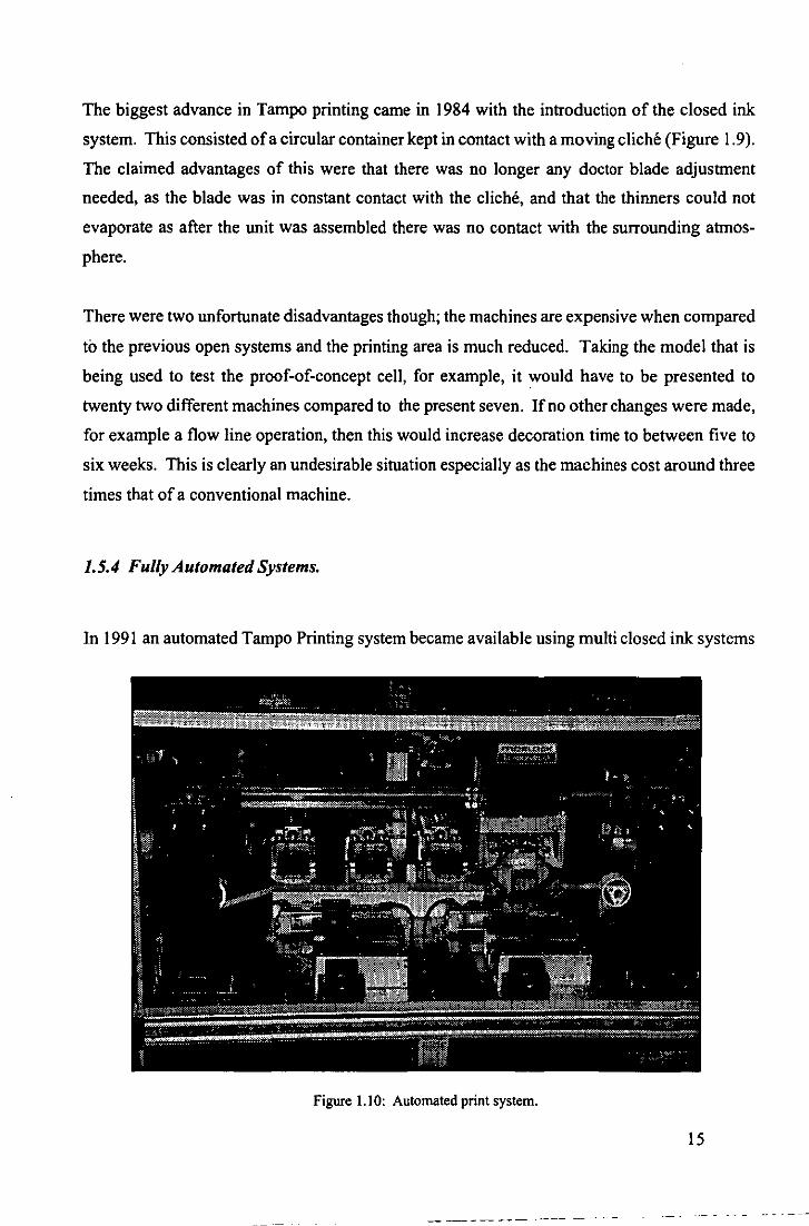
1.5.4 Ful/y Automated Systems.
In 1991 an automated Tampo Printing system became available using multi closed ink systems
Figure 1.1 0: Automated print system.
15

with multi etched cliches, an X-Y ann arrangement using programmable pneumatic cylinders
and a multi-pad rotary head. The manufacturers claim to have solved all of the problems asso
ciated with tampo printing giving very good values for repeatability (better than 0.01 mm), and
the machine occupies a 3 meter square floor area.
The set up time is said to be low, although no indication is given as to how the arm is 'taught'
the various cliche and print points. As yet there is no automatic method for loading or unload
ing the machine even though the work throughput is potentially high so an operative is still
required. Taking the Sierra as a trial sample a cycle time of 60 secs was quoted for complete
decoration.
The cost of £120,000, however, is twenty times that of an open ink machine and nearly eight
times that of a standard closed ink machine.
1.6 THE NEED FOR DECORATION
The current necessity for the decoration of a finished product is overwhelming. It is a sad fact
of life that plain objects just do not sell as well no matter how well it functions or technically
advanced the product may be.
This need for decoration is even more important in the scale model industry where the full sized
prototype is now a very colourful indeed and as such the models have to remain as true as
possible to the real car or train as even the youngest user is very highly critical of the final finish
of the model.
The following two figures illustrate these points. Figure 1.11 reflects how cars used to be in the
mid 1960's with just a number stuck on the doors and bonnet and the current tend in the 1990's
with highly sponsored cars. The Mini was following the trend with a simple stick on number
and the latest cars are using multiple overlay printing.
Put the two cars in Figure 1.12 side by side on a display cabinet shelf and it is obvious which
one is going to sell.
16

Figure 1.11: The improvement in decoration quality.
Figure 1.12: The importance of decoration in the scale model industry
17

1.7 AN HISTORY OF SCALEXTRIC.
Before going further, a brief outline of the history of Scalextric follows so that the reader will
have some understanding of the evolution of the product and may gain an insight into the way
in which the product is marketed.
1952: A small company called Minimodels Limited introduced a range of metal bodied cars
with a novel clockwork motor. These were models of sports and racing cars and their
trade mark was SCALEX.
1956: The inventor/proprietor of Minimodels, Mr. Fred Francis, modified three of the cars to
take an electric motor and devised a rubber based track system with two parallel grooves
in which metal rails carried electric current and guided the cars by means of a 'gimbal'
wheel suspended beneath them. The new product was called SCALEXTRIC (Scalex
electric).These cars were the Austin Healey 100/6, Ferrari 4.5L 375FI and the Maserati
250F.
1957: Scalextrlc was unveiled to the toy trade at the annual Harrogate Toy Fair causing an
immediate sensation, and orders flowed in far in excess of the factory production capa
bility. As an alternative to making substantial investments in a new factory, Minimodels
was sold to the Tri-ang Group in 1958.
1960: Tri-ang launched four new cars fitted with the well tested RX electric motor and accu
rately moulded plastic bodies. A variable speed control replaced the original 'dabber'
type controller. These first true Scalextric cars were the Lotus 16, Vanwall, Lister Jag
uar and Aston Martin DBR and all had stick-on number discs.
1961: A 24 page catalogue revealed a host of racing accessories, bridges and bankings based
on the real items to be found at Goodwood circuit in Sussex. Such was the demand that
a new factory was built solely for the purpose of manufacturing Scalextric. The advan
tage oflarge scale production enabled the cost of individual cars to be reduced from 32/
6d (£1 :62) to 29/11d (£1 :50).
1963: The original rubber track, supplied by a contract rubber supplier, was replaced by a
polyethylene track and was moulded at the Tri-ang factory. By this time the range of
cars had extended to 18 plus two motorcycle combinations and two Go-karts. The two
Formula Junior cars, which had sprung rear suspension and steering, cost 15/11 d (80p)
each.
1964: Scalextric was being manufactured in Tri-ang factories France, Australia and New Zea
land and by an associated company in Spain. It was sold in America in partnership with
18

Lionel, the famous train makers. Jim Clark, the Formula One World Champion, was
retained for promotional purposes and a Scalextric World Championship was staged in
London, to be repeated on alternate years into the 1970's.
1965: Two gimmicks were introduced, the blow-out puncture simulator and Twin Auto
screams, a realistic noise making device not universally popular.
1966: Race Tuned cars were introduced with a significantly higher performance requiring a
more robust hand control. This controller was wired with 'brakes'.
1967: The Scalextric 1124 scale cars were introduced, aimed at clubs and 'slot shops', but
unfortunately they were introduced too late as this market was being eroded by other
interests and only a small quantity were ever made. They were, nevertheless, really beau
tiful models.
1968: A tapering off of demand and the heavy investment in 1/24 meant that prices started to
rise. The only new products were the 'Power Sledge' and the 45° banked track section,
which required special adaptors as the track centres did not match the original track for
some reason.
1970: In an attempt to revive flagging sales another gimmick was introduced 'You Steer', a
special hand control with a small steering wheel. As this was turned it changed the
polarity of the current to the car and by an amazingly ingenious and simple device, made
the car swerve whilst maintaining its forward direction so that it could, to a degree,
avoid obstacles in its path. Although the theory and engineering were sound, the driver
had little time to carry out the manoeuvre. 'You Steer' was not a success and Minimodels
Limited was in some difficulties. The decision was taken to close the factory and trans
fer production to an associated company, Rovex (now called Hornby Hobbies Limited)
at Margate. Rovex produced Tri-ang Hornby model trains and were familiar with the
type of production needed for Scalextric.
1971: A new 60° banked curve was introduced which connected directly to all the other track
sections allowing a banked figure of 8 circuit to be constructed with only 14 track sec
tions. This move has been universally regretted ever since, as to enable cars to use the
banking, it has been necessary to manufacture cars with the front "wheels" clear of the
track and provide a lot of free vertical movement in the axle.
1973: Even so all new sets were supplied with banked cUrves. Three new cars were introduced
of exceptional quality, a Ferrari, JPS Lotus and March.
1977: A start was made with printing the insignia directly onto the cars to replace the transfers
still being used at that time. This immediately improved the quality and durability of the
19
- -- ---
models. Gimmicks were carefully avoided throughout the rest of the 1970's.
1980: The early 1980's were a difficult time with instant appeal of the home computer under
mining Scalextric sales. New ideas were needed.
1982: Trucks were the first of these new ideas taking their lead from the tremendous interest in
Truck Racing in Europe. Unfortunately these were not marketed properly and a golden
opportunity was lost.
1983: . Gimmicks were back. A new blowout set was introduced and a loop-the-Ioop track
section was added. A Trackbusters set was also introduced incorporating special pickup
trucks with 'flip mechanisms' at the rear and using a special transformer so that single
lane 'racing' could take place. None of these gimmicks remained in the catalogues for
long. The first four wheel drive car was introduced.
1986: Electronics started to make an appearance on Scalextric cars. Brakelights on the saloon!
sports cars and 'Turboflash' on the Formula One cars. 'Magnatraction' was introduced
on some cars to improve the performance and handling of the cars. In reality it was
needed as the new motors being supplied were too powerful and the tyres could not
provide the necessary grip for the relatively light cars.
1987: The 30th birthday of Scalextric passed quietly with no mention from Margate.
1988: The interest in the World Sports Car Series was at last satisfied with the introduction of
a Jaguar XJ8 and a Porsche 962 to supplement the continual repaints of old models. The
Super Racing Series of cars from the Spanish factory were included in the catalogue.
1991: The first new car for some years appeared in the catalogue.
1992: Three new cars and 9 re-issues in new 'Power and the Glory' series of 1960's cars,
things seem to be looking up for the rest of 90's.
1993: Two new cars introduced with a modular chassis design to improve production rates.
Horse racing sulkies make an appearance. New track accessories for 1993 are the Pow
er Base Megasound hand throttle to " ... create the right atmosphere for some really seri
ous racing.".
From reading the above it could fairly reasonably be concluded that Scalextric has lurched ~
from one crisis to another in the middle to recent years. Certainly this is true of the manufactur-
ing base, and to a certain extent with not enough thought from the design/marketing teams, and
if it were not for the tremendous loyalty of its customers then neither the name nor the product
would not have survived at all, as there have always been other, and cheaper, systems to choose
from.
20

This is probably a harsh, though true, judgement as today the accuracy of the moulding is
superb and the quality of the colours and decoration outstanding. In 1991 Homby manufac
tured 29 different types of car with a total of 65 different colour schemes at an annual produc
tion rate of 750,000 units. The figures for 1992 were 40 cars (plus Turtles and horses) with 70
colour schemes at a rate ofl,250,000 units and in 1993 35 cars and 71 colour schemes are being
produced plus horses.
1.7.1 Future Plans.
Even though the company has a new model lead time in the order of 18 months, this is not a
luxury it can afford to maintain due to the ever increasing competitiveness of it once partner,
now arch rival, in Spain. Homby Hobbies Limited bought its first CAD workstation in 1989
for the design office. The aim was, and still is, to design all the parts on the workstations in
order to build up a library of standard items to be included in future designs. The ultimate aim
is a paper-less design office.
Another area of particular importance is the manufacture of the dies for the injection moulding
machines. These have been made outside by a tool maker in Margate since the move in 1970
and this has lead to unacceptably lengthy manufacturing times, especially if there has to be a
modification.
Homby hope to shorten this time by generating a 3D model of the product using the software
package Deltacam DUCT, from which the NC machining data can be extracted, and sending
this to the tool maker. Eventually this is planned to be a totally in-house service. This package
can also help to control the injection process itself as it allows for the simulation of the plastic
flow in the mould, and so it can be used to avoid weaknesses and stresses in the finished prod
uct.
21

CHAPTER 2:
CONFIGURING THE CELL.
22

2.1 SUMMARY.
This chapter deals with the various problems that were foreseen at the start of the project, and
outlines the possible solutions; it also deals with those that were not, and which consequently
forced changes to the strategy of the decoration cell.
That there is a need for a decoration cell is not challenged, it is just the precise configuration
that needs careful consideration, especially in view of the recent advances in commercial • off
the-shelf systems. It is felt, though, that the Loughborough approach has been the right one
enabling a deeper understanding of the true nature of the problems experienced with this type
of operation. To date every commercial system has had some level of compromise and it is
hoped that the outcome of the project will show that this need not be the case.
2.2 THE FORESEEN PROBLEMS.
These problems can be split into the following main areas;
• transporting the bodyshells
• handling the body shells
• identifying the bodyshells
• decorating the bodyshells
• inspecting the decorated bodyshells.
2.2.1 Transporting the bodyshells.
This is an important point for many reasons. The various operations are carried out in different
parts of the factory and so the system chosen must be flexible so that it is be capable of dealing
with all the different models produced, trains as well as cars, and not take up valuable floor
space that could be used for other operations.
At present, as the bodyshells are expelled from the moulding machine they drop into a card
board box which, when full, is changed for an empty one. The bodyshells are then manually
23

inspected for 'flash' and moulding flaws before being wrapped in tissue paper and packed in
cardboard boxes prior to being transported somewhere for storage. Eventually they will be
distributed amongst the various printing machines and then on to assembly.
It was not within the scope of this project to investigate in depth the various possible ways of
transporting the bodyshells to the decorating cell, however, one way could be to extend the
existing conveyor systems in the factory. For the purpose of this project, it was assumed that
the same initial inspection of the bodyshells would be maintained and that they would always
arrive at the decorating cell in an upright position.
After consideration, a simple chute loader with a two degree of freedom mechanism was cho
sen as the input to the cell.
As previously stated, presently the bodyshells are inspected, rewrapped and repacked after eve
ry decoration operation. This is very wasteful both in terms of manpower and materials. Also
no orientation is maintained between o~erations. It was thought that it would be to be much
better if the bodyshells could be palletised in some way, then they could be kept in a known
orientation and it would also save on tissue paper and boxes. If they were going to be put in
some sort of storage buffer then the whole pile of pallets could, if necessary, be sealed in poly
thene film or plastic.
Homby Hobbies made some pallets to our design to enable trials to be conducted. To cope with
the various positions on the pallet and the differing height of the pallet stack a simple robot was
required to load them. A UM!' RTX robot this was used for this task.
2.2.2 Handling the bodyshells.
To minimise possible damage to the bodyshells the less they are handled the better. Presently
the bodyshells are handled many times before they are fully decorated, and the printing ma
chine operator has to perform a juggling act with two, three or sometimes four bodyshells at
once. The bodyshells are made from either Acrylonitrile Butadiene Styrene (ABS) or Cellulose
I. Universal Machine Intelligence.
24

Acetate Butyrate (CAB) which, though flexible, is very susceptible to surface damage.
Whatever system is finally chosen to handle the bodyshells it has to be 'surface friendly' in that
it should not mark them. There is one other constraint in that it also has to be capable of picking
them up without distorting them as the bodyshells are fitted onto a precise male mould known
as a matrix (Figure 2.1) during the actual printing operation.
A secondary problem is that because of the
shape of some of the models it is not always
possible to fit them with a straight downwards
motion, they have to be almost rolled on
lengthwise.
The most frequently used grasping principles
are:
• mechanical
• electrostatic
• magnetic
• vacuum
• adhesive.
Figure 2.1 Print matrix used in the decoration operation.
The magnetic principle is ruled out because of the material, the adhesive principle because it
would mark the bodyshells and the electrostatic principle because the electrostatic charge might
repel the paint. The main problem with the mechanical principle is controlling the force ap
plied to the end-effector because the bodyshells deform very easily. The consequence of this
being that it would be impossible to fit the bodyshell onto the matrix.
Therefore the solution is to use a vacuum. The practical way to implement this is through
vacuum cups, also called suction cups. These have a venturi inside the body and all that is
required for successful operation is a stable air supply (Figure 2.2).
Although most bodyshells contain surfaces with recesses and protuberances, it is always possi
ble to find a flat area. However, the size of this area and consequently the size of the suction
25

cup could an operational problem, as
the lift capacity of the suction cup de
pends on the effective area of the cup,
as illustrated in Equation 2.1.
where
F=PA (2.1)
F = the force or lift
capacity, N.
P = the negative pressure,
N/mm'.
A = the effective area' of
the suction cups used to
create the vacuum, mm'.
EXHAUST <;------I
NOZZLE %
" \\
VACUUM
Figure 2.2 The venturi principle.
Because the bodyshells are so light, 17 grams on average, the diameter of the suction cup could
be as small as 5 millimetres to produce the necessary lift capacity. The commercially available
range is from 8 to 400 millimetres and a 10mm cup was chosen.
2.2.3 IdentifYing the bodyshells.
Somewhere in the system there has to be a means of identifying what is entering the decoration
cell. In the simplest case this could merely be a person loading the input buffer with the correct
models for the days production, but the shear tedium of the job would sooner or later lead to
errors. An automatic non-contact (preferably) method is needed.
The things that have to be checked for are:
2 The effective area of the cup during operation is approximately equal to the undeformed area determined
by the diameter of the suction cup. The squashing action of the cup as the object is pulled against it would
tend to make the effective area slightly larger than the undeformed area.
26
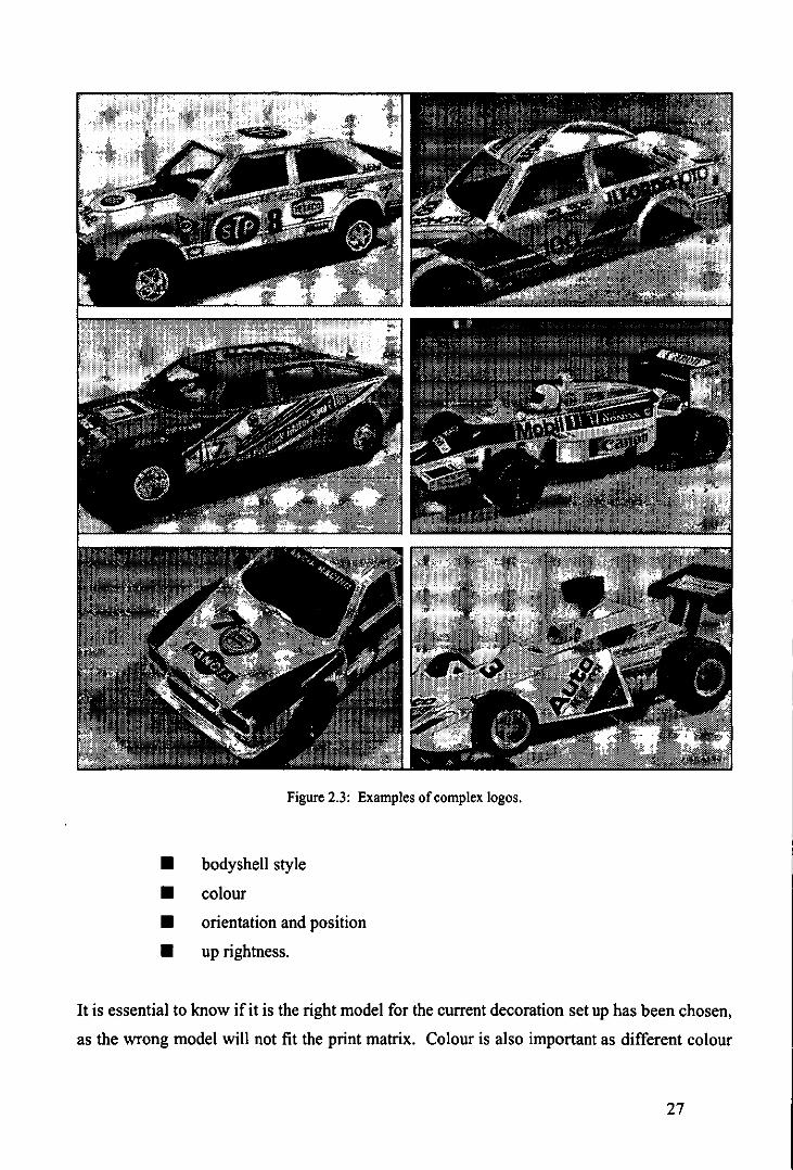
Figure 2.3: Examples of complex logos.
• bodyshell style
• colour
• orientation and position
• up rightness.
It is essential to know if it is the right model for the current decoration set up has been chosen,
as the wrong model will not fit the print matrix. Colour is also important as different colour
27
models require different decorations), and clearly it must be the right way up. Orientation and
position pose the same questions to the handing mechanism.
Bar codes are a possible answer to the fust two questions but not the second two, and it is not
easy to attach them without marking the model or getting them in the way of the decoration.
This may be done on the inside, maybe, but then they would be impossible to read. A sophisti
cated mechanical means could cope with the last two points, and maybe the first, but not the
second. It would also have to be different for every model.
A much more flexible arrangement is to use the same system as does a person, namely vision.
With a colour machine vision system the answer to all the problems is readily obtainable and
can be output in human or machine readable form. This type of system would provide the
greatest flexibility for all current or future production, with, if it was programmed correctly,
very little training for new models.
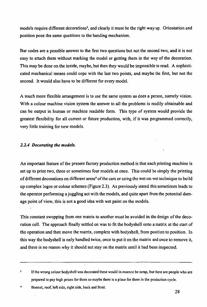
2.2.4 Decorating the models.
An important feature of the present factory production method is that each printing machine is
set up to print two, three or sometimes four models at once. This could be simply the printing
of different decorations on different areas' of the cars or using the wet on wet technique to build
up complex logos or colour schemes (Figure 2.3). As previously stated this sometimes leads to
the operator performing a juggling act with the models, and quite apart from the potential dam
age point of view, this is not a good idea with wet paint on the models.
This constant swopping from one matrix to another must be avoided in the design of the deco
ration cell. The approach finally settled on was to fit the bodyshell onto a matrix at the start of
the operation and then move the matrix, complete with bodyshell, from position to position. In
this way the bodyshell is only handled twice, once to put it on the matrix and once to remove it,
and there is no reason why it should not stay on the matrix until it had been inspected.
4
If the wrong colour bodyshell was decorated these would in essence be scrap, but there are people who are
prepared to pay high prices for them so maybe there is a place for them in the production cycle.
Bonnet, roof, left side, right side, back and front. 28

Obviously this would require some form of fairly specialised handling mechanism that could
get the matrix into the various printing orientations. To achieve the best results with pad print
ing the surface receiving the decoration should, if possible, be horizontal. Certainly with the
models of cars this means that the mechanism must be capable of getting into some interesting
orientations (Figure 2.4).
This matrix-bodyshell approach was suitable for a flow line operation as the mechanism that
transferred them between printing machines' should also transfer them to the inspection station.
As an initial approach to the problem it was decided to use a six degree of freedom robot arm as
this has the capability of reaching complex orientations and also has a large working envelope.
The arm used was a PUMA 5626 and this has allowed valuable lessons to be learned about the
whole strategy.
6
BOOT AND ROOF
BACK
FRONT LEFT HAND SIDE RIGHT HAND SIDE
Figure 2.4: The various orientations adopted by a bodyshell during decoration.
An average number of machines needed for completion of the decoration is seven. Hornby Hobbies did
not provide this number for obvious reasons. The one machine supplied, however, was sufficient to
demonstrate the principle of operation.
Programmable Universal Machine for Assembly.
29

2.2.5 Inspecting the bodyshells.
The logos of the decorated bodyshell need to be inspected for:
• position
• size
• completeness
• shades of colour.
There is only one possible method to carry out this final important task - Vision, either real or
artificial. If it is accepted that human operators are prone to error due to tiredness and boredom
through a repetitive task, then the task defines the only possible ·alternative solution. It also
justifies the purchase of a system for identification as the same system can be used for inspection
by switching cameras with software during the operation of the cell.
All the items selected above for inspection can easily be checked by any suitable commercial
vision system. To buy such a system and plug it into the cell would not be in accordance with
Mechatronic principles, and it probably would not work any way as there are a number of
different items to interface to, and this causes problems when the values of some of the param
eters change.
2.3 THE UNFORESEEN PROBLEMS.
2.3.1 Conveying the models and lighting arrangements.
The first problem was a combination of transporting and identifying the bodyshells. To give
some sort of realistic movement to the bodyshells into the decoration cell a Bosch modular
conveyor system was used. It first had to be established how the bodyshells were going to be
30

conveyed on the workpiece carriers.7 If a carrying jig was used then this would have to be
changed for every model change and it would also be expensive as a large number of jigs would
be needed". As the bodyshells were going to be identified by vision, it was decided to leave
them loose on the workpiece carriers and use the vision system to find them.
It then had to be established where should the camera be mounted and how. Normally cameras
are mounted on some fixed gantry over the area where they are expected to be. This is fine
except that it can restrict the way into and out of the inspection area for the robot. Also if
something goes wrong with the control progranune then quite extensive damage can result.
There is another problem in that the workpiece carriers are a matt black finish and the dark
bodyshells do not stand out from the background. Putting a coloured top onto the workpiece
carriers does not help much as then the light coloured bodyshells do not stand out.
In an effort to try to simulate as nearly as possible the environment at Homby Hobbies Limited,
all of the earlier experiments were carried out using overhead fluorescent lighting which proved
to be very problematical with regard to the identification of the bodyshells by the vision sys
tem. These problems were caused by reflections from the bodyshells and shadows. The reflec
tions were caused by the nature of the bodyshells which are glossy with curved surfaces and the
shadows by the positions of the lights relative to the camera and the bodyshells themselves.
The surface of the workpiece carriers, although described as matt, was also prone to reflections.
Many experiments were carried out with tungsten lights, polarising filters on the camera and
diffusers in front of the lamps but these only went part of the way to solving the problem. The
final experiment with tungsten lighting was to build a station with four horizontally mounted
lamps, level with the conveyor at the corners of the workpiece carrier, and with the overhead
lighting blocked out. This proved to be very successful with lighter coloured models but with
darker models, edge and feature detection were still considerable problems.
The system was now becoming increasingly specialised and in consequence, the working area
for handling the bodyshells was much reduced with very little room for error in movement. At
The tenn used by BOSCH to describe the unit for moving the items around the conveyor system. Usually
referred to as a pallet.
At least at Homby Hobbies, as the trial system was small.
31

this point it was becoming increasing obvious that a complete rethink was necessary to allow
the use of vision to identify the bodyshells. The classical way to illuminate to identify an object
is to use backlighting {Ruocco, 1987}, but how was it possible to backlight through a solid
object?
Various methods were investigated involving lamps and mirrors, but the need to keep the cost
and the overall height of the workpiece carriers down ruled most of these ideas out. After
considerable debate and 'brainstorming'9 the idea was hit upon to 'backlight' by the object by
an indirect means involving the shining of light through the sides of a perspex 10 block, the
horizontal surfaces of which have been specially prepared to maximise the specular reflection
of the light {Trabasso et aI, 1990}. Because the light sources are located at the sides of the
object, the method was called side lighting. (Figure 2.5).
Each perspex block is approximately twice the size of the original workpiece carrier and is
located on top of it by a plate which fits into a recess on top of the workpiece carrier, and is held
in place by a single screw from underneath. The block is lit from two the sides parallel to the
edge of the conveyor by two 60 watt tubular bulbs. A specially made reflector with a small
opening at the front concentrates the light into the perspex block. Because the heat generated
by the bulbs is concentrated into the edge of the perspex block the lamps are only lit for a short
period, just long enough for the vision system to take a picture of the scene to be analysed.
Painting the underneath white and beadblasting the top has helped to sharpen the image and
using the side-lighting system even the reflections on top of the models do not cause problems
any more. Figure 2.6 shows the improvement in image quality produced using this system. A
white bodyshell on a white background (Figure 2.6 a) represents the worst case in terms of
contrast definition, but when backlit (Figure 2.6 b) a very definite shape is highlighted.
The side-lighting arrangement allows for two adjustments, one mechanical and one electrical,
both with a direct effect on image quality.
10
A favoured Loughborough technique for solving 'insoluble' problems, whereby all the people involved in
a project shut themselves in a room and only come out when a viable solution has bel found.
/ ICI trademark or polymethylmethacrylate.
32
•
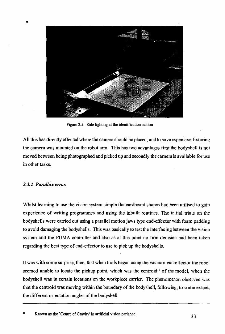
Figure 2.5: Side lighting at the identification station
All this has directly effected where the camera should be placed, and to save expensive fixturing
the camera was mounted on the robot arm. This has two advantages first the bodyshell is not
moved between being photographed and picked up and secondly the camera is available for use
in other tasks.
2.3.2 Parallax error.
Whilst learning to use the vision system simple flat cardboard shapes had been utilised to gain
experience of writing programmes and using the inbuilt routines. The initial trials on the
bodyshells were carried out using a parallel motion jaws type end-effector with foam padding
to avoid damaging the bodyshells. This was basically to test the interfacing between the vision
system and the PUMA controller and also as at this point no firm decision had been taken
regarding the best type of end-effector to use to pick up the bodyshells.
It was with some surprise, then, that when trials began using the vacuum end-effector the robot
seemed unable to locate the pickup point, which was the centroid 11 of the model, when the
bodyshell was in certain locations on the workpiece carrier. The phenomenon observed was
that the centroid was moving within the boundary of the bodyshell, following, to some extent,
the different orientation angles of the bodyshell.
11 Known as the 'Centre of Gravity' in artificial vision parlance. 33

Figure 2.6 (a): Without side lighting. Figure 2.6 (b): With side lighting.
After checking that the errors from the calibration procedures were within the expected limits,
it was concluded that the apparent movement of the centroid was being caused by optical illu
sion. This illusion was caused through viewing a three dimensional object with a two dimen
sional system. This was proved by two independent means, (a) closer visual inspection and (b)
by replacing the bodyshell with a two dimensional object.
(a) Closer visual inspection.
This can be seen in Figure 2.7, where two bodyshells are placed in different locations and
orientations on the workpiece carrier. Note how the centroid12 is different for each bodyshell.
This is caused by certain features of the bodyshell being masked in different locations.
(b) Absence of optical illusion with a two dimensional object.
By replacing the bodyshell with a flat 2-D representation of the bodysheli, complete with win
dow cut outs, the shifting of the centroid vanished (Figure 2.8). There are a number of solu
tions for overcoming this problem of optical illusion such as stereo vision, structured lighting
12 Marked with a cross in the pictures.
34

{Fu et aI, 1987} and artificial intelligence
techniques {Waldon, 1988}. In trying to
keep the solution as simple as possible the
problem was solved by redesigning the
end-effector and fitting sensors around the
vacuum cup (Figure 2.9).
2.3.3 Repositioning device.
This solution brought about another prob
lem in that the grasp point was now no
longer the Centroid of the model, or indeed
a known point. To ensure correct fitting
onto the matrix it is essential to know
where the bodyshell has been picked up.
To overcome this problem a neat reposi
tioning device (Figure 2.10) was construct
ed whereby the bodyshell is dropped into
an angled tray and allowed to slide down
to one corner, whereby its Centroid is then
known. The end-effector can then be repo
sitioned to grasp the bodyshell at the cor
rect position.
2.3.4 Accurate location at the printing
machine and inspection station.
Figure 2.7: The optical illusion phenomenon
caused by lack of depth infonnation.
Figure 2.8: Using a 2·D representation of the
bodyshells.
One quite major problem that had not been fully appreciated at the outset of the project was
that ofthe positional accuracy, or repeatability, of the various robotic arms. When building up
a complex logo very high repeatabilityl3 is called for which is far higher than most manufactur
ers are prepared to quote. As mentioned in Chapter 1 there is no special jigging in use at
Hornby Hobbies Limited for the accurate placement of the matrices in front of the printing
35 " 0.0005" or O.Olmm.

Figure 2.9: The sensors around the vacuum cup.
machines, therefore a design exercise to produce suitable jigging that could be used for both
robotic and manual operation was undertaken. The parameters required were that it should:
• be easily fitted to the worktable at the front of the printing machine
• be adjustable to allow for each surface to be horizontal for printing
• have accurate (>O.Olmm) placement accuracy
• be usable to both the printing machine and the identification station
• be easy to use.
2.3.4.1 Fitment to the worktable.
The adjustable worktable supplied with the printing machines is fitted with 'T' slots, therefore
'T' bolts were the only sensible answer to this problem. This allows for X-Y adjustability.
36
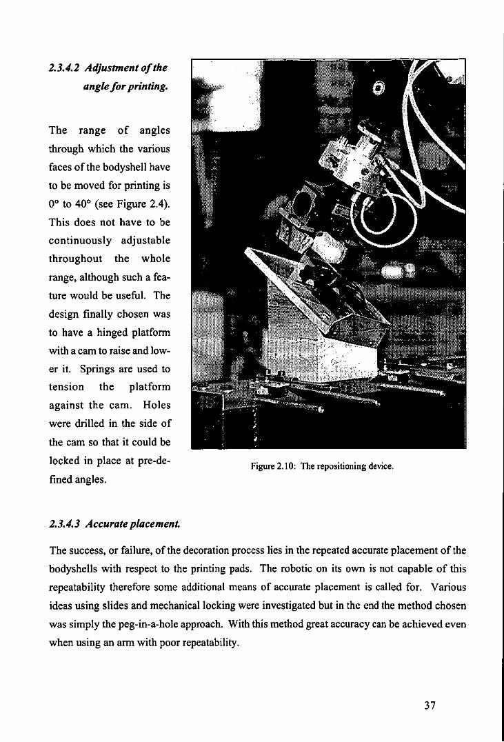
1.3.4.1 Adjustment of the
angle for printing.
The range of angles
through which the various
faces of the bodyshell have
to be moved for printing is
0° to 40° (see Figure 2.4).
This does not have to be
continuously adjustable
throughout the whole
range, although such a fea
ture would be useful. The
design finally chosen was
to have a hinged platform
with a cam to raise and low
er it. Springs are used to
tension the platform
against the cam. Holes
were drilled in the side of
the cam so that it could be
locked in place at pre-de
fined angles.
1.3.4.3 Accurate placement.
Figure 2.10: The repositioning device.
The success, or failure, of the decoration process lies in the repeated accurate placement of the
bodyshells with respect to the printing pads. The robotic on its own is not capable of this
repeatability therefore some additional means of accurate placement is called for. Various
ideas using slides and mechanical locking were investigated but in the end the method chosen
was simply the peg-in-a-hole approach. With this method great accuracy can be achieved even
when using an arm with poor repeatability.
37

Figure 2.11: The arrangement of the pegs and holes
A single peg on its own would not be good enough as this would allow the matrix to rotate
about the axis of the peg. Because the model is divided (for our purposes at least) into three
areas a system of three pegs and four holes was devised (Figure 2.11).
This allows for positioning of the matrix in the three longitudinal positions necessary for print
ing the three identified decoration areas, with at least two of the pegs in use at any position to
maintain the positional accuracy.
2.3.4.4 Interchangeability.
It is not essential to tilt the model so that the surfaces are horizontal for inspection as the proc
ess is simply one of comparison. Therefore a simpler unit could be built without the tilt mech
anism at the inspection station. In fact all that is required is a flat plate with three pegs on it.
The only constraints are that the pegs are on the same centres as those at the printing station and
some adjustment must be built in to align the base with the camera.
38

2.3.4.5 Ease of use.
The system is easy to use in that the matrix is fitted to interchangeable tooling to become the
current end-effector when decorating/inspecting. It is easy for manual use as the matrix can be
locked onto the base unit and the bodyshells changed over as they are at present.
2.4 HAND OVER FROM INSPECTION TO PACKING.
As the RTX robot was going to be used for palletising the decorated bodyshells then some
means of moving them between the two robots was called for. By designing the layout of the
decoration cell so that the workspace of the two robots interfered with each other it would be
possible to effect a direct hand over from robot to robot.
2.4.1 Co-operating robots.
After the models are inspected the PUMA robot arm moves the matrixlbodyshell to a position
that is accessible to the RTX arm and information is sent to the RTX controller informing it of
the result of the inspection operation (pass/fail). The RTX arm is then directed to take the
bodyshell from the PUMA (Figure 2.12) and then either palletise it (pass) or place it in a reject
area (fail) for possible rework.
Using this approach saves on extra jigging in the decoration cell and/or additional handling
devices. The same hand over point can be used with the PUMA for all bodyshells and just the
direction of approach and pick up point with the RTX modified for each type of bodyshell. The
end-effector on the RTX is again a simple vacuum cup with no positional sensing as the precise
location of the pick point is known.
The pallets will obviously have to be changed for ones with different moulds but this would
have to have been done whatever system was chosen.
39

Figure 2.12: Co-operating robots.
2.5 STACKING AND REMOVAL OF THE PALLETS.
No provision has been made for this in the project for, as with the transporting of the bodyshells
into the decorating cell, this is outside the scope of the present project. All that has been as
sumed is that the empty pallets are stacked in the correct orientation on one side of the RTX and
that full ones are removed when the stack is five pallets high. Software has been written to
prompt the operator to carry out these tasks at the appropriate times.
The RTX transfers the pallets from the 'in' side to the 'out' side as they are required. At present
no check is made to find out if pallets are available although this is in the process of being
written. Some form of interfacing between the stack of pallets and the R TX control programme
will also be required, and for the purpose of demonstrations this will probably be just a simple
microswitch.
40
2.6 CYCLE TIME OF THE DECORATING CELL.
Although no desired figure was given to this by Homby Hobbies Limited, it has not been ig
nored during the duration of this project. The theoretical decoration time" for the model being
used in the proof-of-concept cell is one minute, and whilst this is true, at present the actual time
spent in the 'system' is between two and two and a half weeks.
A cycle time of between five and ten minutes was arbitrarily chosen as a starting point to see if
this was an achievable figure. The ideal rate would be 180 per hour as this is the rate at which
the bodyshells are moulded. This would then reduce work-in-progress to zero as they would
then be being decorated at the rate at which they are being moulded.
Once the decorating cell was operating though it soon became clear that the approach adopted,
that of using a single robot to 'feed' the printing machines, was wrong mainly due ~o the wasted
machine time where it was idling and not printing between cycles.
2.6.1 Improvements to the decoration cell cycle time.
To compete with the present manual method each printing machine has to be full for every print
cycle. This effectively means using seven multi arm/end-effector robots in the decorating cell,
or at least the same number of robots as there are printing machines required to complete all the
decorations on each bodyshell. Approaching the problem in this way would make it impossible
to justify the cost of the decoration cell. Another approach was called for.
Another brainstorming session followed where simple multi-arm mechanisms similar to that at
the loading station were explored and rejected. A conveyor approach was finally thought to be
the best approach with a simple loading mechanism and possibly a robot for unloadinglinspec
tionlpalletising at the other.
14 This is calculated by adding the individual operation times for each decoration on the model. These
times are quoted in hours 11000 by Homby Hobbies Limited for accounting purposes.
41

I~
= R
Figure 2.13: Possible solution to the conveyor approach.
New ideas on handling and positional accuracy were needed and one possible approach is shown
in Figure 2.13. This idea itself has now been superseded in the light of current developments in
Tampo Printing technology, and by having investigated the problem in greater depth. These
ideas are discussed in greater detail in Chapter 7.
42
CHAPTER 3:
THE COMPONENT PARTS
OF THE CELL
43

3.1 SUMMARY.
This chapter will concentrate on a detailed explanation ofthe component parts of the proof-of
concept decoration ceIl and explain how the parts are linked in together. The reasons for the
choices were explained in Chapter 2, therefore unless it is felt further explanation is required to
clarify a particular point no reference will be made to the reasons why a particular component
part was chosen.
The interfacing between the component parts is described along with the signals and status
information. A description of the setup procedures for the Tampo print machines currently in
use at Homby Hobbies Limited is also included.
3.2 OVERVIEW OF THE PROOF-OF-CONCEPT CELL
The proof-of-concept ceIl currently consists of five major stations; I) loading, 2) identification,
3) decorating, 4) inspection, 5) unloading. The sixth component is an overall ceIl controIler
Figure 3.1: The Proof-of-Concept Cell.
44

which is at present being developed. This will take the operator through the start-up procedures
and give information about incorrect settings or choices. It is also intended that this controller
will also be used to take the operator through the teaching procedure with new models to
optimise and speed up the operation.
The third function of the controller will be constant monitoring of the proof-of-concept cell
during operation and to signal faults and bring the cell to a halt in an orderly fashion in the
event of a fault.
There now follows a detailed description of the component parts of the proof-of-concept cell.
3.2.1 The loading station.
A chute loading mechanism was chosen as the input to the cell in the belief that this is the best
representation of the method by which the undecorated bodyshells would arrive at the decorat
ing station. The bodyshells on the chute would then slide by gravity into the cell loading area
where they could be removed from the chute and be placed onto the workpiece carriers. After
examining a number of ways for transferring the bodyshells from the chute the configuration
chosen was a simple mechanism with two degrees of freedom, shown schematically in Figure
3.2.
FEEDING
CHUTE
CYLINDERB
Figure 3.2: Principle of operation of the loading station.
CYLINDER A
45

In the rest position both cylinders are retracted. The operation of the mechanism is as follows:
cylinder A is actuated positioning its end-effector (a suction cup) on the roof of the bodyshell
located at the end of the feeding chute, the vacuum is actuated and cylinder A returns to the rest
position lifting the bodyshell from the chute. The remaining bodyshells slide down so that the
next one is positioned at the bottom of the chute. Cylinder B is then activated causing cylinder
A to turn about its pivot point P. This movement places the bodyshell over the workpiece
carrier, the vacuum is switched of and the bodyshell is deposited onto the workpiece carrier.
The cylinders are returned to the rest position ready for the next cycle of operation.
The first design parameter to be calculated was the tilt angle of the chute that would enable the
bodyshells to slide smoothly down it. The minimum value of tilt angle (Elmin) is calculated
through Equation 3.\ :
where:
material.
0. = arctan 11 mm r (3.\ )
11 is the coefficient of friction between the bodyshells and the surface of the chute
The material chosen for the chute was aluminium. The value of 11 between aluminium and
plastic is approximately 0.25 which gives an angle Elmin equal to 14°. The maximum angle of0
was determined experimentally. For angles greater than 400 the bodyshells would tend to tip
over when they hit the bottom of the chute, therefore the tilt angle for the chute must lie be
tween:
140 < El < 400
chute (3.2)
The next step was to calculate the locations of the pivot points for the air cylinders and the
length of the crank. These calculations took into consideration two important requirements:
• the angle of contact between the suction cup and the bodyshells had to be 90° in
order for the suction cup to seal.
• the bodyshells should be released perpendicular to the surface of the workpiece
carrier to guarantee that they would remain in an up-right position. 46

The definitions that follow refer to Figure 3.2. Let P I and P, be the points where the cylinders
A and B are attached, a is the angle of the chute and points T and C are the positions of a
bodyshell over the workpiece carrier and at the bottom of the chute, K is the length of the crank
and S is a line defined parallel to the crank K. The distance between line S and the crank K
corresponds to the stroke of cylinder B.
A sensible way of reducing the number of variables is to impose constraints based on desirable
design features such as having PI and P, aligned. This forces singular values on K, a and d
based on the properties of right angle triangles P"P"T and PI,P"C'.
From triangle PI'P2,T:
By substitution:
Ll a=--
COS e
Finally, the length of the crank is simply:
K = (LI + L2) sin a
(3.3)
(3.4)
(3.5)
(3.6)
The values of LI and L2 are determined by the particular choice of air cylinder; they are the
cylinder stroke and body length respectively. For the particular cylinder chosen L, = 40 mm
and L2 = 165mm.
The value ofa calculated from Equation 3.5 is 26.210 and from Equation 3.6 the length ofK is
91mm. From Equation 3.4 the distance d between the pivot points PI and P2 is 184mm.
Having determined the parameters of the mechanism, the next step was to decide the method of
fixing it by the conveyor. It was decided to fix it directly to the side of the conveyor structure
47
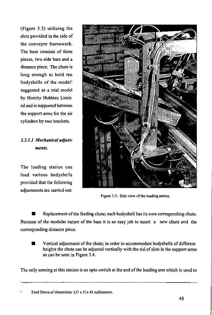
(Figure 3.3) utilizing the
slots provided in the side of
the conveyor framework.
The base consists of three
pieces, two side bars and a
distance piece. The chute is
long enough to hold ten
bodyshells of the model'
suggested as a trial model
by Homby Hobbies Limit
ed and is supported between
the support arms for the air
cylinders by two brackets.
3.2.1.1 Mechanical adjust-
ments.
The loading station can
load various bodyshells
provided that the following
adjustments are carried out: Figure 3.3: Side view of the loading station.
• Replacement of the feeding chute; each bodyshell has its own corresponding chute.
Because of the modular nature of the base it is an easy job to insert a new chute and the
corresponding distance piece.
• Vertical adjustment of the chute; in order to accommodate bodyshells of different heights the chute can be adjusted vertically with the aid of slots in the support arms as can be seen in Figure 3.4.
The only sensing at this station is an opto-switch at the end of the loading arm which is used to
Ford Sierra of dimentions 137 x Six 41 millimeters.
48

Figure 3.4: Front view of the loading station showing the adjustment slots for the chute.
check if there is a model on the chute and ifit has been successfully transferred to the conveyor
system.
The models are transferred from the loading station on specially adapted workpiece carriers
that have a large perspex square on top of them. In the centre of the top face is a small perspex
peg which is the only location for the bodyshells. This enables any bodyshell (car or train) to
be carried without the need to resort to special adaptors.
3.2.2 The identification station.
The identification station consists of two main parts, the side-lighting arrangement and the
pick up mechanism. The basis of the side lighting arrangement was described in Section 2.3.1
and only the mechanical adjustment will be described here. As previously stated the pick up
mechanism is a PUMA 562 series robot.
49

3.2.2.1 Mechanical adjustment.
It was verified experimentally that the light distribution through the perspex block was not
uniform when the reflectors of the bulbs were positioned parallel to the sides of the block. This . is shown in Figure 3.5. The illumination measurements were taken with an exposure meter and
then converted.
illumirnation in LUX at point A B C
21.25 16.75 15.75
REFLECTOR
BULB 20 30 30 30
Figure 3.5: Light distribution through the perspex block.
PERSPEX BLOCK
It was also verified experimentally that the non-uniform distribution oflight through the perspex
affected the reliabilityofsome pattern recognition functions of the vision system. Therefore, a
means of inclining the reflectors in relation to the perspex was required in order to obtain a
more even distribution of light throughout the block.
The ideal angle of the reflectors would be the angle which caused total reflection of the light on
the bottom surface of the perspex, the total reflection angle, which can be calculated by the law
of refraction, also known as Snell's Law. The total reflection angle depends only upon the
50

Figure 3.6: Apperatus used for detennining the total reflection angle of the perspex block.
Figure 3.7(a): Perspex block lit by a 5 mw Helium Neon laser at 0°.
Figure 3.7(b): Perspex block lit by a 5 mw Helium Neon laser at 6°.
51
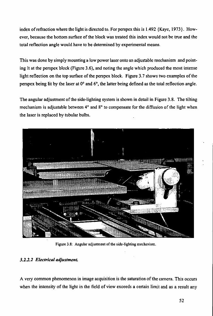
index of refraction where the light is directed to. Forperspex this is 1.492 {Kaye, 1973}. How
ever, because the bottom surface of the block was treated this index would not be true and the
total reflection angle would have to be determined by experimental means.
This was done by simply mounting a low power laser onto an adjustable mechanism and point
ing it at the perspex block (Figure 3.6), and noting the angle which produced the most intense
light reflection on the top surface of the perspex block. Figure 3.7 shows two examples of the
perspex being lit by the laser at 0° and 6°, the latter being defined as the total reflection angle.
The angular adjustment of the side-lighting system is shown in detail in Figure 3.8. The tilting
mechanism is adjustable between 4° and 8° to compensate for the diffusion of the light when
the laser is replaced by tubular bulbs.
Figure 3.8: Angular adjustment of the side-lighting mechanism.
3.2.2.2 Electrical adjustment.
A very common phenomenon in image acquisition is the saturation of the camera. This occurs
when the intensity of the light in the field of view exceeds a certain limit and as a result any
52

output from a vision system which operates with that camera is meaningless.
Unfortunately camera saturation was an observed side effect of the side-lighting system. In
order to overcome this problem the voltage applied to the light bulbs is controlled via a voltage
regulator, and in consequence, so is the intensity of the light shining into the perspex block.
3.2.3 Information requiredfrom the identification station.
When the workpiece carrier reaches the identification station the camera mounted on the PUMA
robot arm is used to analyse the workpiece carrier and its contents. The particular questions
that the machine vision system has to find answers to are:
• Where are the reference marks on the workpiece carrier?
• Is there a known object on the workpiece carrier?
• What bodyshell and colour is it?
• Where is the centre of boundary?
• What is the orientation angle?
The answer to the first question is needed to check the alignment of the workpiece carrier with
the reference frame (see Section 3.5) and to check that the camera is in the correct position by
measuring the distance between the reference marks. If the measurement between the reference
marks is wrong it indicates that the camera is not the correct distance from the workpiece carri
er. If this is so then the object under scrutiny will not be recognised by the vision system as the
measurements will not match with those of the reference object.
The answers to points two and three will reject the object if it is not in the library of known
shapes or not the right bodyshell for the present decoration set-up, while the answers to four
and five will be sent to the robot controller to update the model reference location so that the
bodyshell can be grasped safely. To pick the bodyshell from the workpiece carrier a suction
gripper is employed which has sensory feedback in the form of four optical switches.
This feedback is essential because of the problems experienced with viewing a 3-D object with
a 2-D system in that the centre of boundary appears to "move" depending upon the orientation
53

and position of the object. The pick point for the car being used in the proof-of-concept cell is
near the front of the roof and parallax error can move this preventing the suction gripper from
working properly. Should this happen signals from the sensors arranged around the suction
gripper are used to instruct the robot to move so that the gripper is over the centre of the roof.
This means that the current grip point is no longer the centre of boundary of the bodyshell and
so a method of re-positioning has to be used so that the correct pick point can be located again
(Figure 3.9).
Figure 3.9: The principle of operation of the repositioning device.
This operation is essential as a special printing block called a matrix is needed to prevent the
bodyshell from deforming during printing. The matrix is an exact mould of the bodyshell and
therefore the bodyshell has to be positioned with great accuracy to prevent damage or jamming.
54

3.2.3.1 Re-positioning device.
As can be observed in Figure 3.9 the re-positioning device is extremely simple. It is also very
reliable as the bodyshells always end up aligned against the sides of the device, they simply
slide by gravity along the bottom surface of the device.
The material of the bottom surface is perspex and the angles of the stand were calculated through
Equation 3.2, 11 in this instance is the co-efficient of friction between plastic and perspex. The
top surface is initially inclined at 31 0 relative to the horizontal and then by 21 0 relative to the
bottom left corner (Figure 3.10). It is worth mentioning that the re-positioning device also
cancels out any errors from the robot-vision calibration procedures and the vision system meas
urement routines.
Figure 3.10: The inclination angles of the repositioning device.
The necessity for using the re-positioning device was arrived at after evaluating the effort re
quired to cancel out the optical illusion error by software or electronic means. In some
mechatronic products one can identify the integration between the three fields as a way of
aiding the achievement or simplification of the mechanical requirements of the product, viz the
autofocus camera. In the re-positioning device however, this trend is broken as any other
method would be extremely difficult to carry out.
55

3.2.4 Decoration station.
The decoration station is in two parts: tool changer and tampo print machine. The tool
changer is required because the robot has to pick the bodyshell from the workpiece carrier and
transfer it to a matrix. The matrix then has to be taken to the tampo print machine.
3.2.4.1 Tool ch anger.
The tool changer
presently used in the
decoration station
(Figure 3.11) was de
signed and built as a
final year student
project {Roach,
1989} and has since
been modified to al
low it to work suc
cessfully within the
proof-of-concept
cell. The modified
tool changer still ex
hibited certain opera
tional difficulties and
in consequence a
new mechatronic tool·
changer was devel
oped (Figure 3.12) to
overcome these diffi
culties. The underly
ing idea behind the
mechatronic tool
changer was that it 3.11: The original tool changer.
should be possible to unlock/lock the different end-effectors anywhere within the robot
56
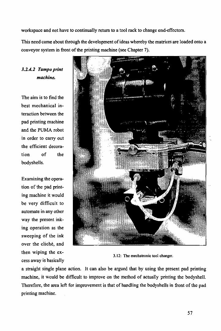
workspace and not have to continually return to a tool rack to change end-effectors.
This need came about through the development of ideas whereby the matrices are loaded onto a
conveyor system in front of the printing machine (see Chapter 7).
3.2.4.2 Tampo print
machine.
The aim is to find the
best mechanical in
teraction between the
pad printing machine
and the PUMA robot
in order to carry out
the efficient decora-
tion of the
bodyshells.
Examining the opera
tion of the pad print
ing machine it would
be very difficult to
automate in any other
way the present ink
ing operation as the
sweeping of the ink
over the cliche, and
then wiping the ex-
cess away is basically
a straight single plane action.
3.12: The mechatronic tool changer.
It can also be argued that by using the present pad printing
machine, it would be difficult to improve on the method of actually printing the bodyshell.
Therefore, the area left for improvement is that of handling the bodyshells in front of the pad
printing machine.
57

The main mechanical requirement is that the matrix should always be placed accurately under
the silicone pads. Another requirement, and one none the less important, is that there should be
room for the service personnel to be able to set the machine up for each decoration. There are a
number of potential solutions to the problem and those that were tried are reviewed in section
3.4. These ideas have led to a the possibility of a completely new design of pad printing ma
chine that will be outlined in Chapter 7.
3.2.5 The inspection station.
Figure 3.13: The inspection station.
Inspection is carried out automatically by the machine vision system at a custom designed
inspection station (Figure 3.13). The final version will consist of a frame with 3 cameras and
three lamps. A locating device similar to that at the printing machine is utilised. Each car is
divided into three sections (front, middle and back) and the robot positions the matrixlbodyshell
on the locating device so that each section can be inspected in turn.
There are reference marks on the matrix and these are used to check the location of the matrix
58

as well as the positional accuracy of the decoration on the bodyshell. The decorations are also
checked for completeness and colour. The bodyshell will be rejected if any of these three items
is wrong, likewise, if the printing machines have been set up with the wrong decorations then
this will also cause the bodyshell to be rejected as the database will not recognise these as
correct for this particular model.
This 'failure' information will eventually be made available to the decoration station so that
corrective action can take place.
It is worth mentioning the problem with focusing the cameras when inspecting the roof, bonnet
and rear of the car. The problem arises because these areas are different distances from the
camera and because of the short focal length ofthe lens used they cannot all use the same focus
setting. Using an autofocus lens is one solution but this is very costly. A cheaper a more
mechatronic method would be to use a mechanical adjustment on the camera frame so that the
camera was moved relative to the model.
The lights used at the inspection station are standard domestic clip-on spotlights with 25 watt
bulbs. Using higher power bulbs can cause 'flare' on the bodyshell an hence cause problems
with the inspection.
The present design concept of the inspection station is that it will be used to inspect fully
decorated bodyshells, but there is no reason why partially decorated bodyshells should not be
inspected either after each decoration operation or to check the printing machine set up. Bear
ing in mind the original overall concept of utilising up to seven tampo print machines to deco
rate the bodyshells, then for partial inspection after each operation an inspection station will be
required after each machine hence increasing the cost considerably but on the plus side allow
ing defects to be spotted earlier in the decoration cycle.
3.2.6 The unloading station.
Models that pass inspection have to be transported to assembly, or storage in the case of the
present factory working method. Presently the completed bodyshells are wrapped in tissue
paper to prevent damage and then packed in cardboard boxes before being taken from the deco
ration area. 59

This method has three distinct disadvantages;
a) it is very labour intensive,
b) any orientation knowledge gained during the decoration cycle is lost
c) it is very costly in terms of tissue paper.
Therefore any automated system must be capable of;
• maintaining orientation
• preventing damage
• ease of transportation and storage
3.2.6.1 The matrix/pallet concept.
A very simple way of maintaining orientation is to use trays which have hollows into which the
goods are placed, this also has the added advantage of preventing damage to the goods by
preventing them moving around. An easy method of moving trays of goods around is to
palletise the trays. Therefore by carefully defining the problems associated with handling the
decorated bodyshells a sensible solution presented itself.
Figure 3.14: The component parts of a pallet. 60

Figure 3.15: An assembled pallet.
In this case instead of using a hollow tray it was decided to use a tray with a raised hollow
matrix. Homby Hobbies were asked if they could manufacture the trays to our design and
initially they were in agreement, but problems with the vacuum moulding meant that they were
actually made as individual hollow matrices (Figure 3.14). Homby Hobbies also provided
separate bases onto which the hollow matrices could be stuck in groups of six (Figure 3.15).
The size of the base is 20 cm x 30 cm and the overall height is 9 cm. The complete pallet weighs
0.850Kg.
3.2.6.2 The 'H' shaped suction end-effector.
With the matrix/pallet concept, there are two distinct actions that have to be performed by the
RTX robot:
a) it has to transfer a pallet from the stack of empty pallets to where the bodyshells will be
loaded onto the pallet
61

b) it has to transfer the bodyshells from the inspection station to the pallet if it has passed
inspection or to reject/rework if it is has not.
Because of the serious limitations of the RTX in terms ofrepeatability and programrning2, the
use of a tool change mechanism was ruled out. This led to the design of the dual purpose end
effector shown in Figure 3.16.
It consists of an H
shaped plate with five
suction cups attached
to it, one in the centre
and one at the end of
each of the four
'arms'. The central
cup is used to carry
the bodyshell and the
others for transporting
the palIets. Figure
3.17 shows the RTX
performing these two
distinct actions.
The solution for trans
ferring the bodyshells
from the inspection
station to the unload
ing station was found
by causing the work
areas of the PUMA
and RTX robots to in
tersect at one point.
Therefore, it is possi
ble for the RTX robot
Joint level programming.
Figue 3.16: The 'H' section end-effector used on the RTX robot.
62

Figure 3.17: The two actions perfonned by the 'H' section end-effector.
to remove the inspected bodyshell directly from the matrix end-effector of the PUMA robot.
This simple solution can be thought of as a mechatronic alternative to that of having an extra
mechanical link between the inspection and unloading stations. It only requires simple soft
ware routines to implement the changeover.
3.3 THE TAMPO PRINTING MACHINE.
The major feature of the decoration process in use at Homby Hobbies Limited is the use of
open ink well Tampo print machines. These are very costly in terms of man hours to set up and
waste due to evaporation of the thinners, but until comparatively recently these were the only
types available.
For this reason it will be instructive to follow the procedures necessary to put one of these
machines into an operational state. It must to remembered that these procedures have to be
gone through for each decoration setup, and there are seven machine changes required3, with a
scheduled setup time of three hours each time therefore the machines are effectively idle for
For the Ford Sierra used as a trial model. 63

three single shift days during the production ofthis bodyshell. The other important point that
has to be remembered is that each machine has to cleaned down after the last shift and reset
ready for the ftrst shift the next day. Therefore it really comes down to at least 3 man hours/shift
not per operation.
3.3.1 Setting up.
CLICHE SPACING BAR INK TRAY
DffiPLATE
Figure 3.18: Fitting the cliche onto the die plate.
The ftrst operation is to ftt the printing plate (cliche) onto the die plate (Figure 3.18) ensuring
that it is level with the surface of the spacing bar. Failure to do this could result in the doctor
blade and/or spatula catching on either the cliche or spacing bar and causing damaging to one
or all of them. Ink must now be mixed and added to the well at the rear of the machine. This is
the ftrst of many 'black arts' associated with the system as the precise mix of paint and thinners
depends on many variables. Ambient conditions and print area being just two. If more than
one colour is required then separators are fttted into the ink tray.
With reference to Figure 3.19, stage two of the setting up procedure is to fit the Ink Unit (a)
onto the printing machine, attach the tampons (printing pads) (b) to the Pad Mounting Plate (c)
and ftt them into the Pad X, Y Holder Unit (d) on the machine. The doctor blade and spatula (e)
are then fttted onto the Doctor Blade Mechanism Holding Bar (f) and the machine started up so
64

d • ......_---f e
c
a
Figure 3.19: The component parts of a Tampo Printing Machine.
that the doctor blade can be adjusted to clean the cliche properly. This sounds easy but in fact
there are 38 separate adjusting screws on the doctor blade plus five possible air pressure/move
ment adjustments to be made. Even skilled operatives can spend almost one hour on this oper
ation alone.
During this operation the ink consistency is almost certain to require adjusting many times to
retain, or even modify, the original 'specification'.
Having obtained a satisfactory sweeping/wiping operation the next stage is to fit the matrices
(f) onto the worktable (g) at the front of the machine, this currently is a very hit and miss affair
as no proper jigging exists at the factory to achieve this. After fitting, the machine is restarted
and the tampons and matrices are adjusted so that the decoration is placed in the correct posi
tion on the model.
Again more adjustment of the ink consistency will be called for along with frequent cleaning of
the tampons.
The tampo print machine is now ready for use after approximately 3 hours of setting up time.
In this period it would have been possible to decorate maybe 1500 cars, not fully but at least
65

with one 'set' of decorations, had a better system been in use and the machines capable of
continuous operation.
3.4 INTERFACING BETWEEN COMPONENTS.
There are four main control units employed in the proof-of-concept cell;
• PLC' for the conveyor system
• MX Magiscan for the vision system
• V AL 11 controller for the PUMA
• Victor PC for the RTX robot.
3.4.1 Loading station.
The PLC is interfaced with the loading station, the inspection station and the PUMA controller.
When a workpiece carrier arrives at the loading station a signal is sent to the PLC to operate the
loading mechanism to place a bodyshell onto the workpiece carrier. The sensor beside the
vacuum cup on cylinder A (Figure 3.2) informs the PLC if there is no bodyshell ready or if the
transfer was not completed correctly. If the transfer was successful the workpiece carrier is
released to carry the bodyshell round to the identification station. The lack of a bodyshell or an
incorrect transfer will signal an error, which at present requires manual intervention.
3.4.2 Identification station.
When a workpiece carrier arrives at the identification station the PLC sends a signal to the
PUMA controller that a workpiece carrier is waiting. When the PUMA arm is in the 'photo
graph' location and the 'workpiece carrier waiting' signal is active then the PUMA controller
sends a signal to the PLC to switch on the lights in the identification station. The MX controller
is then instructed to take a photograph of the workpiece carrier and its contents. After a pre-
4 Programmable Logic Controller.
66

detennined time a signal is sent to the PLC to turn off the lights.
After the MX controller has analysed the picture the object on the workpiece carrier is either
accepted or rejected. Depending on the reason for the rejection, at this stage manual interven
tion may still be needed. If the object on the workpiece carrier is accepted then infonnation
regarding its position and orientation on the workpiece carrier is sent to the PUMA controller.
This infonnation is then used to update the reference location of the object and the robot is then
driven to pick up the object.
3.4.3 Decorating station.
Some of the front panel controls on the tampo printing machine are duplicated in software in
the PUMA controller and along with some additional switches these provide. the necessary
timing to ensure that the PUMA presents the matrixlbodyshell to the tampo printing machine at
the correct time in the print cycle. The only other signal infonnation from the decorating sta
tion is the status of the tools on the tool changer, this will be used when the cell starts up to
check which tools are fitted onto what rack on the tool changer and to check that they are
correctly located.
3.4.4 Inspection station.
When the PUMA robot places the matrixlbodyshell at the identification station the PUMA
controller sends a signal to the MX controller to photograph the bodyshell. If the reference
marks on the matrix are not in the correct positions the MX controller sends a signal to the
PUMA controller to reposition the robot. After the matrix has been successfully positioned the
MX controller sends further information to both the PUMA controller and the RTX controller
concerning the results of the inspection routines, this at present is simply in the fonn of pass or
fail. Routines are being written to output more specific data regarding failure infonnation
which can then be used in an analysis of the proof-of-concept cell performance.
67
--- ~~---- --------

3.4.5 Unloading station.
The only other interaction between the unloading station and the PUMA controller is when the
PUMA robot reaches the 'change over position' and a signal is sent to the RTX controller to
remove the bodyshell from the matrix. When this operation has been completed a signal is sent
from the RTX controller to the PUMA controller to inform it that the cycle can start over again.
68

------- -- ----
CHAPTER 4:
THE SOFTWARE USED IN THE CELL.
---- -- -
69

4.1 SUMMARY
This section describes the software of the proof-of-concept cell. It is not the author's intention
to reproduce all of the programmes written, but rather to give an overview of the general
structure of the software and the interaction between the different programmes. In places part
of the code is given to either clarify a point or to make it easier to follow the reasoning.
One inescapable fact is the number of different languages used in the cell as shown in Table
4.1.
Table 4.1: Tbe various high level languages used in the proof-of-concept cell.
STATION
Loading
Identification
Decoration
Inspection
Unloading
LANGUAGE
PLC mnemonic code
MS-Pascal and V AL II
VALII
MS-Pascal and VAL II
Forth and VAL II
Obviously it was not a deliberate ploy to use such a disparency of languages. Rather these
languages come as standard with the various component parts of the cell. It just shows the
diversified range of languages that have to be mastered when integrating a range of standard
equipment.
The software to generate the pattern recognition database was written in Microsoft (MS) Pascal
as this was the language used by Joyce-Loebl to write the code for the Magiscan Vision Sys
tem. To make full use of the procedures already available in the vision system library however,
a knowledge of the structure of the vision system is also called for. This will be reviewed 70

briefly in section 4.3.
4.2 SOFTWARE SYNTHESIS.
4.2.1 Loading station.
The control of the loading station is via the PLC. This section gives the PLC code for control
ling the stop/release gates on the conveyor system at the loading station as well as the control of
the loading mechanism itself.
In addition to the proximity switches and solenoid valves used for controlling these actions,
two more switches and valves are shown in Figure 4.1 as a means of starting and ending this
section of code.
'j \...
Figure 4.1: PLC input/output allotment at the loading station
71

In Figure 4.2 the X's represent the signals which are loaded into the PLC, Y's the outputs from
the PLC to the various valves and M's the internal relays used for setting up the clock registers
represented by T's. Refer to lines 5 and 6 for setting up clock T450. This pattern is repeated
for the other three clocks. These are used to implement a delay of 1.0 second between the
various actions of the loading mechanism.
The PLC is programmed via a set of 22 basic instructions in its own mnemonic code. Examples
are LD (LoaD), LDI (LoaD Inverse), S (Set), R (Reset), OUT (OUTput), AND (AND) and so
on. For the complete set refer to Mitsubishi {1987}. After allotting the input/output numbers
to the various sensors and actuators to be controlled by the PLC the progranuner has to write a
flow chart and then convert this into the mnemonic code. This is best expressed as a ladder
diagram. The section of code shown in Figure 4.2 contains the commands for stopping and
releasing the workpiece carrier as well as the control of the loading mechanism.
14 ID [X403] ANI [X403] ................................. S [VS31] 17 ID [X404] .•................................................ R [YS31)
: ................................................ S [Y444]
t::::::::: ::::::::::::::::::::::::::::::::::::::: ~ ~ 22 ID [M3OO] .................................................. (T4SO) [K 1.0] 25 ID rr4SO] .. ; ..................... ;-....................... R [Y444]
; ................................................ R [M3OO] ~ ............................................... S [M301] : ............................................... S [M307)
30 ID [M3OO] AND [XS14]···~····························· R [M303]
!:::::::::::::::::::::::::::: ~ g:l ; ............................ R [M307) ; ............................ R [M301] ; ............................ S [M302] : ............................ S [Y433]
39 ID [M301] ................................................. (T4S1) [K 1.0] 42 ID rr4S1] .................................................... R [Y442]
: ................................................ R [M301] : ................................................ S [M302]
46 ID [M302] ............................................... (T4S2) [K 1.0]
49 ID [TS42]T:::::::::::::::::::::::::::::::::::::::::::::: ~ =] . S [M303] :............................................... R [M307J
54 ID [M303].~:::::::::::::::::::::::::::::::::::::::::::::::. (T453) [K 1.0] 57 ID [f453]....................... .. . ..... .......... ......... S [y 433]
~ ............................................... R [M303] 60 ID [X412] AND [X4OSJ-., ............................... R [y442]
: ............................... R [M303] 63 IDI [X40S] ANI [X406] .. ; ............................... R [Y433]
. : ............................... S [yS32)
Figure 4.2 Part of the PLC mnemonic code showing the routine for the loading station
72

With reference to Figure 4.1, a workpiece carrier can enter the loading station if it is empty, this
condition is represented by the instruction ANI 404 at step 15.
When the workpiece carrier gets to the loading position, access to the next workpiece carrier is
denied in step 18 (R [Y53 I]) and the sequential actions of the loading mechanism are instigat
ed, the suction cup is positioned over the bodyshell at the bottom of the chute step 19 (S [444])
and then the vacuum is activated (S [Y 440)). The next action is to return cylinder AI, to its rest
position at step 26 (R [Y 444)) which lifts the bodyshell from the chute. The delay mentioned
earlier is placed between these last two actions to ensure that the cylinder returns to the rest
position only after it has reached the bodyshell and the vacuum operated. The only other way
to do this would be to fit limit switches to the cylinders and wait for them to be activated.
Steps 30 - 38 are the recovery actions if the bodyshell is not there or is dropped during the
transfer from chute to workpiece carrier.
Step 43 (R [Y 442)) activates cylinder B moving the bodyshell over the workpiece carrier, a
delay was found to be necessary here as operating cylinder B at the same time as returning
cylinder A to its rest position often resulted in the bodyshell being dropped. The vacuum is
deactivated at step 50 and after a further delay the gate of the loading station is operated (line
19) allowing the workpiece carrier to move out of the loading station and cylinder B is returned
to its rest position at step 62 (R [Y442]). Finally the gate is closed at step 65 (R [Y433]).
4.2.2 Identification station.
This section presents the software used by the vision system and the PUMA robot-vision sys
tem interface. The software is slit into two parts: off-line and on-line called OWLDB' and
OWL respectively. The off-line part is used in the generation ofthe pattern recognition and the
vision-PUMA calibration databases which are then used by the on-line software for identifying
2
Cylinders A and B of the loading mechanism in Figure 3.2.
OWLDB is short for OWLDataBase. The three main programmes of the proof-of-concept cell are OWL,
EAGLE and PUFFIN, which control the vision system, PUMA and RTX robots respectively.
73

PATIERN RECjNTIlON
OWLDB (off-line)
GENERATION
I CALIBRATION
ASSES.SMENT
• OWL (on-fine)
I
I INSPEcrION
I
Figure 4.3: Structure of the off·line programme of the identification station
the bodyshells and managing the robot·vision interface.
To make the software user friendly the generation of the inspection database was also included
in OWLBD. The operator can therefore generate all the databases needed through a single
programme. The structure of OWLDB is represented in Figure 4.3. The generation of the
pattern recognition and calibration databases will be described in section 4.3 and the inspection
database in Section 4.4.
4.2.3 Decoration station.
The software of this station consists of three sub·routines in TUCANO which take control of
the Tampo printing machine. They are:
• SWEEP.TAMPO· continuously keeps the doctor blade/spatula carrier sweeping
ink over the .cliche when the PUMA robot is not at the Tampo printing machine.
• STOP.TAMPO - stops the Tampo printing machine so allowing the PUMA robot
to manoeuvre the matrix in front of the printing machine. 74
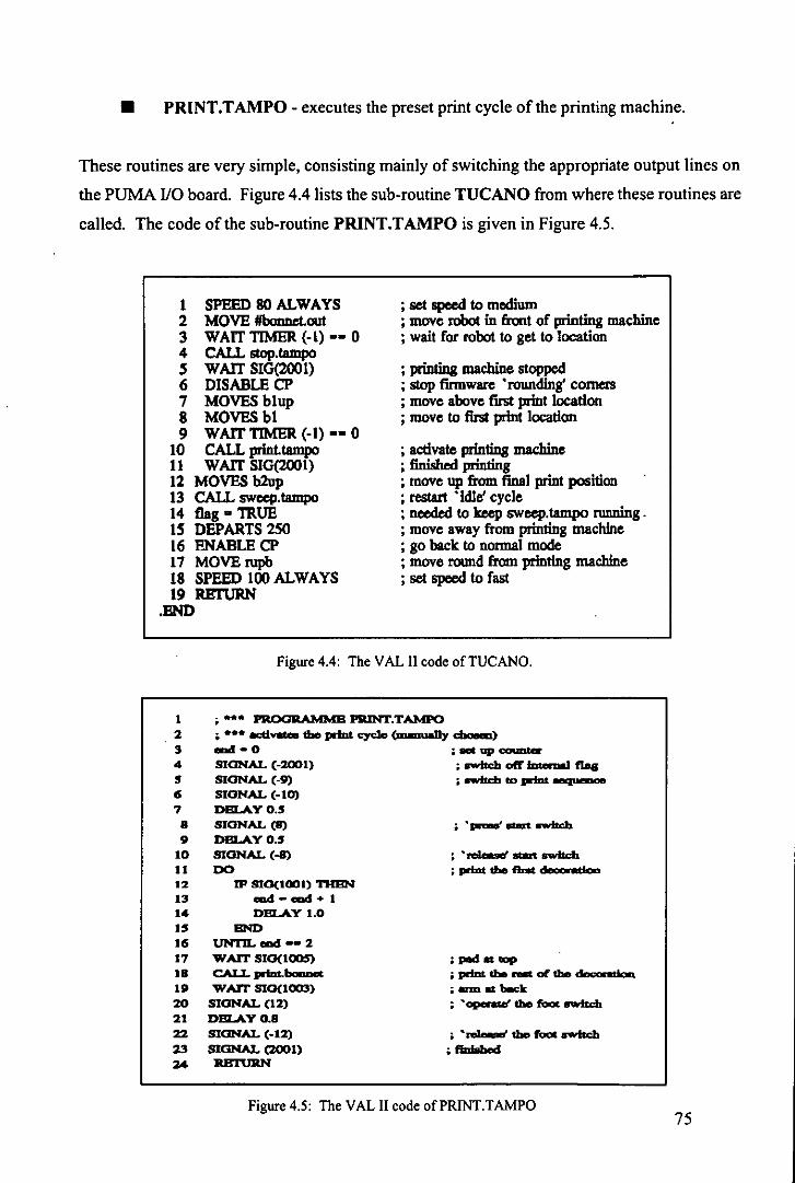
• PRINT.TAMPO - executes the preset print cycle of the printing machine.
These routines are very simple, consisting mainly of switching the appropriate output lines on
the PUMA I/O board. Figure 4.4 lists the sub-routine TUCANO from where these routines are
called. The code of the sub-routine PRINT.TAMPO is given in Figure 4.5.
1 SPEED 80 ALWAYS 2 MOVE lIbonnd.out 3 WAIT TIMER (-I) •• 0 4 CALL stop.tampo ~ WAIT S1G{200l) 6 DISABLE CP 7 MOVES blup 8 MOVESbl 9 WAIT TIMER (-I) •• 0
10 CALL print.tampo 11 WAIT S1O(2OOI) 12 MOVES b2up 13 CALL sweep.tampo 14 flag a TRUE 1~ DEPARTS 2SO 16 ENABLECP 17 MOVErupb 18 SPEED 100 ALWAYS 19 REnJRN
.END
; set speed to medium ; move robot in front of printing machine ; wait for robot to get to location
; printing machine stopped ; stop finnware • rounding' corners ; move above first print location ; move to first print location
; activate prlnlillg machine ; finish...! printing ; move up from final print position ; restart • idle' cycle ; needed to keep sweep.tamp<> running. ; move away from printing machine ; go back to normal mode ; move round from printing machine ; set speed to fast
Figure 4.4: The V AL II code of TUCANO.
1 • *** PROORAMMB PIUN'T.TAldPO 2 •••• IICdVllta tile pdD1 cyc10 (m_nneD,. ~)
:3 ..t: - 0 ; 8et up c:ounter 4 SIGNAL (-2001) , ....trch off .......... fIIoa 5 SIGNAL (-9) , __ to pdDt_
6 SIGNAL (-10) 7 DBLAYO.5
8 SIGNAL (8) , • __ ... ....trch
9 DBLAYO.5 10 SIGNAL (-8) , ._ ... _ 11 DO ,print ___ ___
12 JP SIO(IOOI) THBN 13 cad - cad + 1 14 DELAY 1.0 15 END 16 ~CIDd--2
17 WArr SIO(I005) la CAU.-ptm._ 19 W Arr 810(1003) 20 SIGNAL (12) 21 DBLAYO.8 22 SIGNAL (-12) 23 SIGNAL (2001) :z4 RBnlRN
,pedot_ , print _ ... of the __
;; ann _ beck. , • __ the _ owfsdt
;flnlsb ....
Figure 4.5: The VAL II code ofPRINT.TAMPO 75

4.2.4 Inspection station.
The vision system inspects the decorated bodyshells for:
• position and completeness of the decoration
• smudging
• shades of colours.3
The inspection is based upon a comparison of the decorated bodyshell with that of a reference
model. All the relevant features of the reference model are derived off· line and stored in a
database. The on-line inspection programme reads in this database and compares the features
of the decorated model with that in the database.
In a way this process is similar to that of pattern recognition although it is simpler in that the
correlation of the features is not relevant, i.e. if the position of the decoration is incorrect then
this gives the inspection software a basis for a decision, it is clearly not necessary to investigate
further.
The programmes were derived with a feature which makes the decoration inspection very quick
and reliable: windows allocation {Trabasso et aI, 1991 f}.
The principle of windows allocation is very simple: the off-line programme allows the user to
define windows around the features to be inspected, and the origin and size of the various
windows are recorded in the inspection database. The on-line programme rebuilds these win
dows and then scans the first one. If the relevant decoration is found and its attributes are
within the preset tolerances the next window is scanned and so on, otherwise the bodyshell is
rejected at the first window.
This windows allocation approach allows for a tremendous reduction in the number of pixels
scanned. In the bonnet inspection of the Texaco Sierra, for example, the number of pixels
scanned is reduced by 97% from 64,536' to 2,000 pixels.
4
This is not fully implemented as it requires a colour vision system. The inspection of shades of colour with
a monochrome system is explained later.
Half resoultion of the MAGISCAN vision system. 76

4.2.5 Unloading station.
PUFFIN is the programme which controls the RTX robot, it is written in Forth and structured
in elementary units caJled words. A word in Forth corresponds to a procedure in Pascal or a
sub-routine in V AL n. With reference to Figure 4.6, it is easy to foJlow the actions performed
by the RTX robot just by looking at the PUFFIN source code'.
The word REC receives action data from the PUMA robot via the RS-232 link and stores them
in the variable DECISION. Based upon the current value of this variable the RTX robot car
ries out one of the foJlowing actions:
6
• DECISION = 84: (ASCII' code T for tray) the RTX robot moves the top transport
tray from the 'empty' stack to next position on the 'load' stack where the decorated
bodysheJls which pass inspection will be paJletised
• DECISION = 66: (B for bin number) after identifying a bodysheIl at the identifica
tion station the vision system sends the RTX controJler the corresponding bin num
ber. The word STORE_DATA stores this variable in the array MODELS.
• DECISION = 80: (P for paJletise) the bodysheJl has passed inspection and the
RTX paJletises the bodysheJl. The word PALLETISE is composed of the longest
chain of words within PUFFIN as it involves interaction with the PUMA robot and
the PLC as weJl the updating of a number of arrays and variables.
• DECISION = 102: (ffor fail) this teJls the RTX controJler to place the next bod
ysheJl in the reject/rework box.
• DECISION = 83: (S for stop) This is the stopping code. The PUMA robot control
ler sends the same signal to the vision system and the PLC as well. After receiving
this code the RTX robot returns to its HOME position.
Note that some structures common to most programming languages are written in different order in Forth.
The corresponding structure ofline 5 in Pascal is: IF DECISION = 84 THEN ....
American Standard Code for Information Interchange. 77

o : PUFFIN {MAIN PROGRAMME} 1 CLEAR..SCREEN 0 COUNT! 0 DECISION! 0 MODELS ! 2 A TIACH_GRIPPER 3 BEGIN 4 REC DECISION! 5 DECISION @ 84 - IF FIRST_TRAY 6 ELSE DECISION @ 66 - IF STORE_TRAY 7 ELSE DECISION @ 80 = IF PALLETISE 8 ELSE DECISION @ 102 .. IF REJECT 9 THEN THEN THEN THEN
10 DECISION @ 83 - UNTIL 11 CR. " Finishing" CR HOME CR ." Finished" CR ; 12 13 14 IS
Figure 4.6: The PUFFIN source code.
The main action of the RTX robot is the palletisation of the correctly decorated bodyshells. An
overview of the corresponding code follows. The initial action of the word PALLETISE is to
read the first value of the array MODELS. This will decide which bodyshell will be palletised
and onto which transport tray. The array MODELS is updated and the code moves down to the
next word. Based on the value of a counter this word decides on which of the six possible
locations on the tray the bodyshell will be placed.
Even though there are 30 palletising positions only 6 needed to be taught to the RTX as the co
ordinates for each tray differ only in height. When the value of the counter reaches six the
RTX robot places a new tray on the 'load' stack, taking into account the number of trays al
ready on the stack.
Figure 4.7 gives an example of the code needed to palletise the Ford Sierra at the first position
ofa transport tray. ABOVE_PUMA and FROM_PUMA are taught locations. Note the way
the RTX controls the vacuum ON and OFF in lines in lines I and 7. The command BIT is used
to control the output port linked to the PLC which switches the solenoid valves linked to the
suction cups ON and OFF accordingly. This is a somewhat tortuous path but it avoided build
ing another interface between the RTX controller and the valves. 78
-I
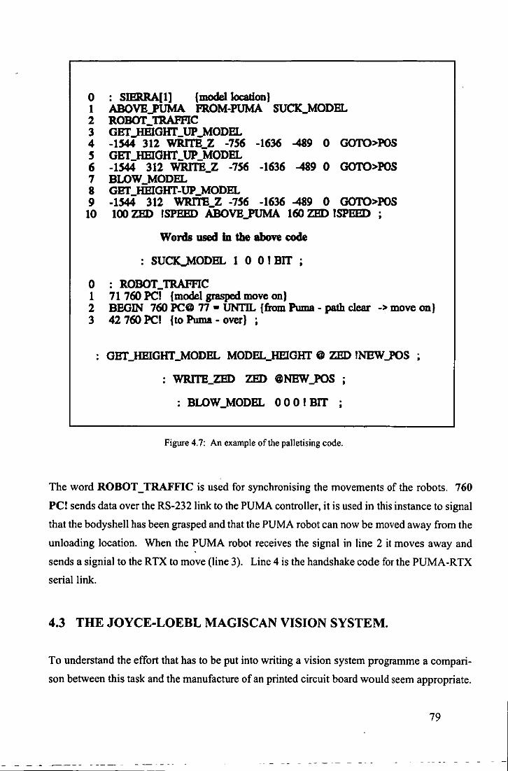
o : SIERRA[I] {model Jocation} 1 ABOVE PUMA FROM-PUMA SUCK~ODEL 2 ROBOT':::TRAFFIC 3 GETJIBIGIIT_UP~ODEL 4 -1544 312 WRlTB_Z -756 -1636 -489 0 GOTO>POS 5 GET_HEIGIIT_UP _MODEL 6 -1544 312 WRlTB_Z -756 -1636 -489 0 GOTO>POS 7 BLOW_MODEL 8 GET_HEIGIIT-UP _MODEL 9 -1544 312 WRlTB Z -756 -1636 -489 0 GOTO>POS 10 100 ZED ISPHBD ABoVEJ'UMA 160 ZED ISPEED
Words used In the above code
SU~ODEL 1 0 0 1 BIT
o : ROBOT_TRAFFIC 1 71 760 PCl {model grasped move on} 2 BEGIN 760 PC@ 77 - UNTIL {from Puma - path clear -> move on} 3 42760 PC! {to Puma - over} ;
GETJIBIGIIT_MODEL MODELJIBIGIIT @ ZED lNEWJ'OS •
WRlTB_ZED ZED @NBW_POS ;
: BLOW_MODEL 0 0 0 1 BIT ;
Figure 4.7: An example of the palletising code.
The word ROBOT_TRAFFIC is used for synchronising the movements of the robots. 760
PC! sends data over the RS-232 link to the PUMA controller, it is used in this instance to signal
that the bodyshell has been grasped and that the PUMA robot can now be moved away from the
unloading location. When the PUMA robot receives the signal in line 2 it moves away and
sends a signial to the RTX to move (line 3). Line 4 is the handshake code for the PUMA-RTX
serial link.
4.3 THE JOYCE-LOEBL MAGIS CAN VISION SYSTEM.
To understand the effort that has to be put into writing a vision system programme a compari
son between this task and the manufacture of an printed circuit board would seem appropriate.
79

After defining the functional requirement of the circuit board the designer then has to decide
how to connect components in order to achieve the desired result. The majority of the electron
ic components needed are available off the shelf, such as diodes, transistors, resistors and inte
grated circuits. Sometimes the designer has to resort to designing specific components but this
is only in the case of a very specialised circuit board.
Keeping this comparison, the MAGISCAN vision system can be thought of as a shelf from
which the various 'components' for 'assembly' of a programme can be taken. It is up to the
programmer to assemble these components in the necessary order to achieve the desired result.
As various electronic components can be found in a single chip so can various routines in
MAGISCAN be found in units. For instance, the unit MXRT contains the routines to execute
operations with images such as addition, subtraction, edge enhancement and so on; the unit
MXTYPES contains all types' used in MAGISCAN, starting with a simple constant such as n up to complex records composed of a number of fields. All the units can be compiled separate
ly from the users programme. For a complete description of the MAGISCAN units, refer to
Joyce-Loebl {1987}.
For accessing the routines of these units, the programmer has to declare them in the header of
his programme and subsequently link the object code of the programme to the object code of
the units. This is done using the DOS linker.
A typical user programme that makes use of the MAGISCAN units is shown in Figure 4.8.
Normally only the executable code is supplied with a MAGISCAN vision system, but Joyce
Loebl supplied an 'open version' to the Department of Mechanical Engineering to enable work
to proceed with this project. This allows for some useful modifications to the original proce
dures, for instance the inclusion of new parameters to be output from a particular procedure. It
also allows for the inclusion of totally new procedures into the units.
The following were added to the original units:
• MXPUMA: all the procedures for communication with the PUMA robot including
Pascal structure.
80
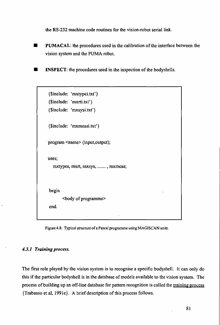
the RS-232 machine code routines for the vision-robot serial link.
• PUMACAL: the procedures used in the calibration ofthe interface between the
vision system and the PUMA robot.
• INSPECT: the procedures used in the inspection of the bodyshells.
{$include: 'mxtypei.txt'}
{$include: 'rnxrti.txt'}
{$include: 'rnxsysi.txt'}
{$include: 'rnxmeasi.txt'}
program <name> (input,output);
uses;
rnxtypes, mxrt, rnxsys, ....... , rnxmeas;
begin
<body of programme>
end.
Figure 4.8: Typical structure ofa Pascal programme using MAGlSCAN units.
4.3.1 Training process.
The first role played by the vision system is to recognise a specific bodyshell. It can only do
this if the particular bodyshell is in the database of models available to the vision system. The
process of building up an off-line database for pattern recognition is called the training process
{Trabasso et aI, 1991 e}. A brief description of this process follows.
81

. The bodyshell is presented to the vision system at a reference position chosen by the operator.
The position is recorded as the template position and later used as the reference point for calcu
lating the orientation angle of the bodyshell. The sampling process then takes place whereby
the vision system takes fourteen measurements of the bodyshell, nine of them related to the
internal features and the remainder based upon the external features, {Joyce-Loebl, 1985}.
Some of the measurements have physical meaning such as perimeter, area,length, width. Some,
however, are made up in order to improve the results of the training process. For example the
quantity perimeter x distanceS is frequently used.
After the first set of measurements has been processed the bodyshell is moved to a new posi
tion, the same measurements are taken and the database is updated. This sampling process is
repeated until a significant database for the model has been constructed. The number of sam
ples depends on the complexity of the object being viewed. Based on experimental results, the
minimum number of samples for the actual bodyshell being used is twenty.
4.3.2 Flowchart and data file output.
Figure 4.9 shows a typical data file output which contains the statistical database of an object to
be used with the classification routines.
• Number _ oC measurements
• Edge_detection Jactor
• Feature_detection Jactor
• Reject_con fi dence _Ieve I
• Filter size
• Object_name
• Bin number
• Template_data
• Measurement vector
• Covariance _matrix
Figure 4.9: Typical data file structure.
Distance is the distance between the actual centre of area to the centre of area of the object at the template
position. 82

A library contains up to twenty such data files, i.e. it is possible to place twenty different ob
jects in a single library. The MAGISCAN vision system allows for up to ten different libraries.
There is a practical criterion for placing different objects in a library. That is to select objects
with similar levels of contrast relative to the background; this prevents light and dark coloured
objects being placed in the same library. The contrast level is reflected in the edge and feature
detection factors. Figure 4.\ 0 shows the flowchart of the training process.
4.3.3 Off-line assessment.
Before using the data generated by the training process in an on-line programme the operator
has the option of assessing the results of the training off-line. All that is required is to place the
object of interest in the field of view of the vision system either in the position it will be pre
sented to the vision system or in a totally random position. The programme checks to see ifthe
object belongs to the library selected and outputs the following information:
• Object name and bin number
• Orientation angle
• Confidence level.
This process should be repeated a number of times. The indication of a successful training
process is thatthe confidence level stays at the highest possible value 9 for all positions and that
the orientation angle does not exceed ± 2° when the bodyshell is not moved.
4.3.4 Vision system PUMA robot calibration.
The measurements taken by the vision system are expressed in pixels and these then have to be
converted into metric units for the robot controller to be able issue movement instructions to the
robot arm. MAGISCAN provides a straightforward method of converting pixels into millime
tres using light pen calibration. All that has to be done is to place an object of known length, a
ruler of example, into the field of view and using the light attached to the system draw a line
83
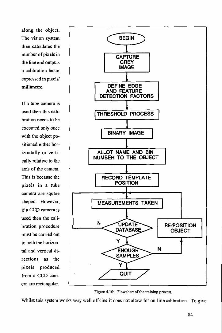
along the object.
The vision system
then calculates the
number of pixels in
the line and outputs
a calibration factor
expressed in pixelsl
millimetre.
If a tube camera is
used then this cali
bration needs to be
executed only once
with the object po
sitioned either hor
izontally or verti
cally relative to the
axis of the camera.
This is because the
pixels in a tube
camera are square
shaped. However,
if a CCD camera is
used then the cali
bration procedure
must be carried out
in both the horizon
tal and vertical di
rections as the
pixels produced
from a CCD cam
era are rectangular.
r
C BEGIN
CAPTURE GREY IMAGE
DEFINE EDGE AND FEATURE
DETECTION FACTORS
1 THRESHOLD PROCESS
r BINARY IMAGE I ALLOT NAME AND BIN
NUMBER TO THE OBJECT
RECORD TEMPLATE POSITION
MEASUREMENTS TAKEN I l
N UPDAT RE-POSITION DATABASE OBJECT
~ ENOUG N SAMPLES
Yi
/ QUIT 7 Figure 4.10: Flowchart of the training process.
Whilst this system works very well off-line it does not allow for on-line calibration. To give
84

the system the capability of on-line calibration the workpiece carriers had calibration marks
built into them. These are small black circles on the top face of the perspex machined 250
millimetres apart and can easily be detected by the vision system. Because the size of the
calibration marks are small and known the vision system can be instructed to ignore them when
analysing the contents of the workpiece carrier, but they can be used for on-line calibration
when required.
A full description of the calibration procedure is given in Trabasso and Zielinski {1990}.
Figure 4.11: The calibration marks on the workpiece carriers.
4.4 GENERATION OF THE INSPECTION DATABASE.
This will be described taking the decoration of the bonnet of a Texaco Sierra as an example.
Obviously all the procedures described here are just as valid for other parts of the model as they
are for a completely different model.
To generate the inspection database it is first necessary to position the reference model in the
85

inspection station using the PUMA robot. A typical view of the image to be analysed by the
inspection station is shown in Figure 4.12. Note the reference marks in this figure; they are the
two small white circles on the right edge of the image just inside the windscreen area. These
marks are used for two purposes a) to check if the matrix has been positioned correctly and b)
as reference positions when checking the locations of the various parts of the decoration on the
model.
In an image with different contrast levels, as is the case in this example, the operator can split
the inspection operation into two or three stages if necessary. In this example the inspection is
split into light and dark features which correspond to the white and red printing. After obtain
ing a binary image through the thresholding process the operator selects the relevant features of
the image.
This step is necessary because sometimes a reflection from the lighting system might be present
in the binary image and it has to be disregarded by the inspection process. Figure 4.13 shows "
the result of the thresholding process applied to the grey image of Figure 4.12.
Figure 4.12: Typical image at the inspection station.
86

Figure 4.13: Binary image of the bonnet highlighting light features.
The operator is then prompted with the screen shown in Figure 4.14. In this particular example
he should enter the numbers 1,5,2 and 4 respectively to select the four features of interest. The
same operation is repeated for the dark features if required. That is because the operator is
given the option of a complete or partial inspection, for instance it is possible to inspect only the
white star of the Texaco logo and ignore the red circle underneath or vice-versa.
After the decoration selection, the programme calculates the features of the decorations. The
first is the perimeter, this is used to check if the logo is smudged or only partially printed.
For recording the position of the decoration the programme calculates the distance square"
between the centre of the boundary of the decoration and the centre of boundary of one of the
reference marks. The orientation of the decoration is calculated as the angle between its longest
diameter relative to the horizontal plane of the vision system.
The information about the shades of colour of the decoration can also be obtained despite the
use of a monochrome vision system. This is achieved through window allocation and the grey
scale: the operator defines a small window'o which lies on a certain colour. The inspection
10
This is to avoid the extra calculation of the root square.
Which contains approximately 50 pixels. 87

PLERSE PICK OUT THE WHITE FERTURES BY
SelECTING THE CORRESPONDING NUI'IBER
FERTURE
BOTTOI'I REFERENCE
I'IRRK
TOP REFERENCE
I'IRRK
TEXRC 0 STRR
NU I'IB E R SIX
NUI'IBER
I
Figure 4.14: Computer screen of bonnet white features selection.
routine then calculates the mean grey level of the pixels inside the window according to equa
tion 4.1. np Egl; i=\
GL= (4.1) np
The grey scale of the MAGISCAN vision system runs from 0 (darkest) to 63 (lightest) and can
be used for a great number of different shades of colours. It has been successfully used with the
bodyshell being tested for the purpose of inspection. Clearly this method will fail if it is used
for identifying colours. The gl values of black and dark blue for instance are so close as to
make "them meaningless for identification, but for comparison purposes the technique holds.
After calculating the perimeter, position, orientation and mean grey level of a decoration, the
programme prompts the operator with windows definition and positioning. The system initial
ly positions the bottom left corner of the window at the centre of boundary of the decoration.
The operator defines the size of the window and re-positions its origin in order to enclose the
decoration using the light pen. When all of the windows have been defined successfully the
inspection database is generated.
88

A typical structure of an inspection database is presented in Figure 4.15.
Note that the threshold values associated with the reference marks and the decorations are also
recorded. This makes it absolutely essential to have the lighting conditions of the on-line in
spection set to the same level as that used to generate the database.
Inspection_code } Total or partial inspection
Threshold min, Threshold max - -Ref.mark_x, Ref.markJ } Top reference mark
Window_x, WindowJ }
Window_~x, Window_~y }
Ref.mark_x, Ref.markJ } Bottom reference mark
Window_x, WindowJ }
Window_~x, Window_~y }
Threshold _ min, Threshold _ max } First decoration
Window_x, WindowJ }
Window_~x, Window_~y }
Perimeter }
Distance_to Jeference }
Orientation_angle }
Mean ~ey Jevel }
Threshold min, Threshold max } Second decoration - -Window_x, WindowJ }
Window_~x, Window_~y }
Perimeter }
.....
Figure 4.15: Typical data structure of the inspection database.
89

4.5 THE ON-LINE PROGRAMME - OWL.
Section 4.4 described the action of the off-line programme OWLDB. The data generated by
this programme, namely the pattern recognition and calibration databases, is used by the on
line programme in order to:
• identify the bodyshell on the workpiece carrier
• drive the PUMA robot to pick up the bodyshellfrom the workpiece carrier.
To identify a bodyshell the vision system again takes a set of measurements and compares it
with the database, and based upon the distance from the set in the database, will either accept or
reject it. There is a tolerance that has to be set in the classification process in order for the
bodyshell to be accepted as a member of the database. This tolerance level is defined as the
confidence level of the process and is set by the user. The minimum and maximum levels in the
MAGISCAN system are 0 and 9 respectively. After successfully identifying a bodyshel\ the
vision system sends the following information to the PUMA robot:
• Bin number, which uniquely identifies each model in the library
• The x and V co-ordinates of the centre of boundary of the bodyshell, already trans
formed into robot world co-ordinates by the factors in the calibration database
• Orientation angle, which is measured from the reference model in the database.
With this information the PUMA robot programme EAGLE modifies the location of the centre
of boundary of the bodyshell as follows:
SET<bodyshell> = TRANS (x,y,z,o,a,t)
where x, y and 0 are sent by the vision system, and z, a and t are set by the operator: z is the
height of the bodyshel\ measured from the workpiece carrier, a and t are the angles which K
determine the complementary orientation of the robot gripper. Figure 4.16 shows a simplified
flowchart of the on-line programmes.
90

OWL EAGLE
/ Z.A. T FROM/ OPERATOR
BINARY IMAGE
1 A
W I MEASUREMENTS TAKEN I
VECTOR CALCULATIONS
O~~ COMPOSE LOCATION
N IDENTIFIED
? BODYSHELL
Y +-GRASPED
CALCULATE THE ORIENTATION
ANGLE BODYSHELL AT
RE-POSITIONING STATION
CALCULATE THE CENTRE OF BOUNDARY
CHANGE TOOUNG
TRANSFORM INTO ROBOT
WORLD PUT BODYSHELL CO-ORDINATES ON MATRIX
Figure 4.16: Flowchart of the interaction between OWL and EAGLE.
91

CHAPTER 5:
THE ELECTRONIC AND ELECTRICAL DESIGN OF THE CELL.
92

5.1 SUMMARY
This chapter presents the electrical and electronic design of the five component parts of the
proof-of-concept-cell. It also covers the sensors and associated electronics employed.
Compared to the mechanical and computer design stages the electronics design was much sim
pler in that most of the equipment used was readily available off-the-shelf, such as the PLC,
camera/computer interface and most importantly the robot controllers.
When mentioning the equipment used the author will limit the information to that which is
relevant to the proof-of-concept cell. Further details can readily be obtained in the suggested
references.
An important part of the control of the cell is the communication between the various compo
nents using an RS-232C serial link, and this will be described.
Because the PLC is also used for control at the identification station and unloading stations as
well as the conveyor system, it will be reviewed in a general manner. This will make it easier
to describe its particular use in the various parts of the proof-of-concept cell later on.
5.2 THE RS-232C SERIAL LINK.
In serial data transmission one data bit is transmitted after another. In order to transmit a byte of
data it is therefore necessary to convert incoming parallel data into a serial bit stream which can
then be transmitted along a line.
Serial data transmission can be synchronous (clocked) or asynchronous (non-clocked). The
latter method is by far the most popular method. The rate at which data is transmitted is given
by the number of bits transmitted per unit time. The commonly adopted unit is the 'baud', with
one baud roughly equivalent to I bit per second.
It should, however, be noted that there is a subtle difference between the bit rate from the
computer and the baud rate in the transmission line. This is simply because there is some
93

overhead in tenns of the extra synchronising bits required in order to recover asynchronously
transmitted data.
In the case of a typical RS-232C link, a total of eleven bits are required to transmit only seven
bits of data. A line baud rate of 600 baud, therefore, represents a data transfer rate of around
382 bits per second.
The interface is defined by the Electronic Industries Association (EIA) and relates to the con
nection of data tenninal equipment (DTE) and data communication equipment (DCE). For
many purposes the DTE and DCE are the computer and peripheral respectively although the
distinction is not always so clear as, for example, in the case of two computers being linked via
RS-232C ports. In general, the RS-232C system may be used where the DTE and DCE are
physically separated by up to 20 meters or so at a baud rate of 19 .2Kbaud - although at the low
baud rates distances can be up to 400 meters. For greater distances telephone lines are usually
more appropriate.
The EIA specification allows for the following signals:
• serial data comprising
(i) a primary channel providing full duplex data transfer'
(ii) a secondary channel also capable of full duplex operation
• handshake control signals
• timing signals.
RS-232C is versatile and highly adaptable; unfortunately such flexibility carries a penalty - the
wide variation in interpretation, which can result in some bewildering anomalies in the physical
connection and control of practical RS-232C systems.
The most commonly used signal lines are shown in table 5.1. For a full description of the RS-
Simutaneous data transmission and reception. 94

Table 5.1; The most popular pins implemented in an RS-232C serial link.
PIN NAME ABBREVIATION
I Frame ground Fa 2 Transmit data TX
3 Receive data RX
4 Request to send RTS
5 Clear to send CTS
6 Data set ready DSR
7 Signal ground sa 8 Data carrier detect DCD
20 Data terminal ready DTR
232C interface refer to Seyer {1984}. Because only 8 of the lines are normally used many
computer manufacturers are now using 9 way 'D' connectors to save space on the back panels.
This wiring is, however, not standard and can vary from manufacturer to manufacturer.
The minimum possible configuration of an RS-232C link is three lines as shown in table 5.2.
The PUMA controller is only provided with this minimum configuration so that it was neces
sary to implement the handshake routines between the component parts by software.
Table 5.2; The minimum configuration of an RS-232C serial link.
PIN NAME ABBREVIA nON
2 Transmit data TX
3 Receive data RX
7 Signal ground sa
To establish a reliable link between computers and peripherals using RS-232C certain criteria
have to be met. These are: 95

• Baud rate of the transmitting and receiving units must be the same
• A buffer must be available in which the data can be temporarily stored during trans
mission
• Software management of the transmission line must be established.
The software to support such a link varies from computer to computer; for instance, in V AL II
there is a special set of instructions called the Z-instruction set, in FORTH the instructions
PC@ and PC! are used and in Microsoft Pascal the routines have to be written in assembler and
then used as a procedure.
5.3 PROGRAMMABLE LOGIC CONTROLLER.
Up to the late 1960's electromechanical relay panels were the standard technique for accom
plishing sequential control in industrial applications: after that date Programmable Logic Con
trollers were introduced as a replacement for them. A PLC, like a relay panel, is made up of
multiple relays, timers and counters. However, the internal wiring in a PLC is executed by
programming, making PLC's smaller, more reliable and flexible.
According to the manufacturers of PLC's they are defined as digitally operating devices with a
programmable memory and are capable of generating output signals according to the logic
operations performed on the input signals. In a typical industrial system the inputs to a PLC are
provided by limit, proximity or photo-electric switches and outputs are used to drive motors,
solenoid valves, lamps, electromagnetic clutches and so on.
The functions that a typical PLC can accomplish are:
• Control relay functions: generation of an output signal based on the logic
rules applied to the inputs
• Timing functions: generation of an output signal for a specified length of
time, for example
96
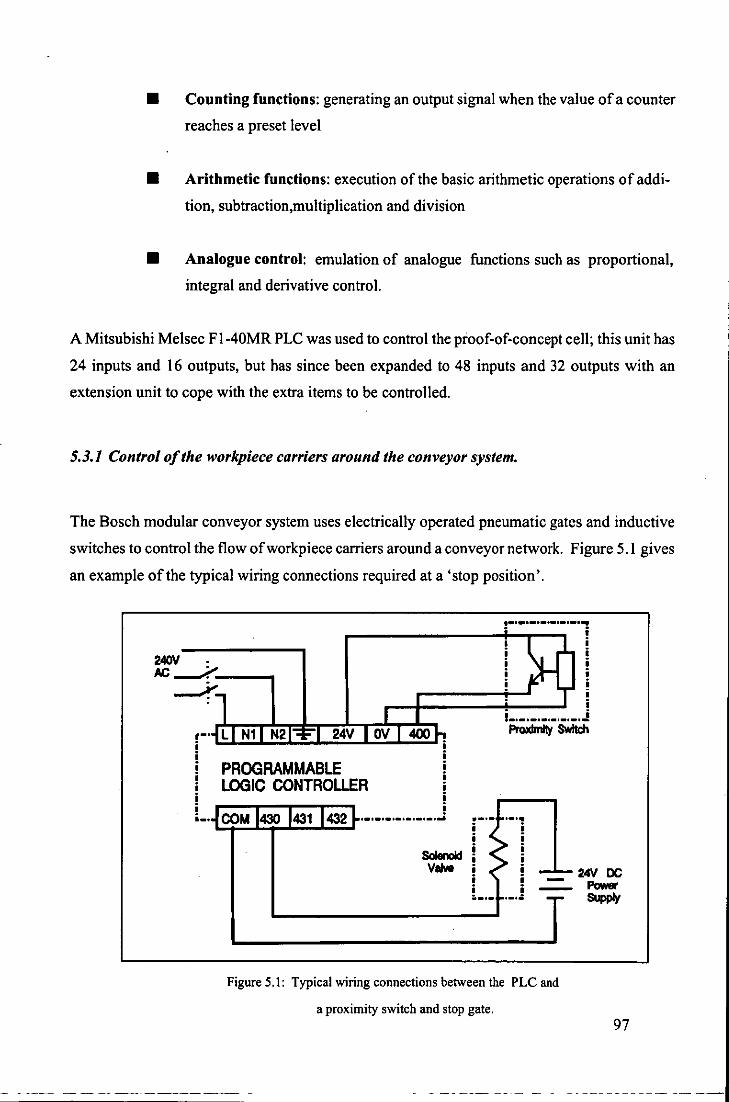
• Counting functions: generating an output signal when the value of a counter
reaches a preset level
• Arithmetic functions: execution of the basic arithmetic operations of addi
tion, subtraction,multiplication and division
• Analogue control: emulation of analogue functions such as proportional,
integral and derivative control.
A Mitsubishi Melsec F l-40MR PLC was used to control the proof-of-concept cell; this unit has
24 inputs and 16 outputs, but has since been expanded to 48 inputs and 32 outputs with an
extension unit to cope with the extra items to be controlled.
5.3.1 Control of the work piece carriers around the conveyor system.
The Bosch modular conveyor system uses electrically operated pneumatic gates and inductive
switches to control the flow of work piece carriers around a conveyor network. Figure 5.1 gives
an example of the typical wiring connections required at a 'stop position'.
~~~~~~~~~~~~i
PROGRAMMABLE LOGIC CONTROLLER
i i i i i i .................
SolenoId VeNa
!-.-.-.-.-.-.-.~
i •.• o.o •.•.•••• _
ProxImIty SWItch
,.,. i i i i i i i '.'.
24V DC Power SUpply
Figure 5.1: Typical wiring connections between the PLC and
a proximity switch and stop gate. 97

The programme instruction between the two components could simply be:
LOAD 400 - - - - - - - - - OUTPUT 430
Which would be represented in the ladder diagram as:
X 400 [I (Y 430)
This instruction means that the PLC will scan the status of input 400 and when it goes high
(positive) then the output transistor 430 will be pulsed on. If the output is required to be turned
on for longer periods then it is necessary to resort to using internal relays to achieve this.
In addition to connecting the stop gates and the proximity switches to the PLC, the lift units at
the ends of the traverse sections of the conveyor system also have to be controlled to enable the
workpiece carriers to flow smoothly around the conveyor system.
'(XI
PUMA 'DO
'" \, OJ
00'
... "
~ u ~
::J
" ::J
-' Q. Q. ~ Z ::J ,,\
Q. 0
'" ." >n
" OD'
® DC ""I~. fIOV. O. ~A. IllOl'lPI1 OOJ ~~lJI\AlIC t~1[ 0 Z e UJ
m u cc 1(11011. '200II. (I. '1.0... 1l'1JIP!I ~'-"E TIC SEHSOR UJ
-'
8 oc IIOIOI'. )11XN. o.~ ..... l~'O,"",
~ m.ENOIO VIoLV£
Figure 5.2 Schematic of the PLC connections in the proof-of-concept cell.
Figure 5.2 shows the PLC connections to the solenoid valves and the proximity switches neces-
--------- - - - - --
98
.----- - - - --

sary for control of the workpiece carriers around the conveyor system as well as the connec
tions to the PUMA and RTX robots. Solenoid valve 433 and proximity switch 412 control the
workpiece carriers at the loading station, and solenoid 431 and proximity switch 414 control
them at the identification station. The other solenoids and proximity switches are necessary for
holding the workpiece carriers while they wait to enter the various stations.
5.4 ELECTRONIC SYNTHESIS OF THE FIVE STATIONS.
5.4.1 Loading station.
The control requirements of this station are:
• stop and release the pallets at the loading position
• execute the sequential movements of the loading station
• monitor the presence of the bodyshell in the loading station.
It was decided to use the same PLC that was controlling the conveyor system for the first two
requirements and an opto-switch for the third.
5.4.1.1 Sequential control of the loading mechanism.
The components necessary for controlling the sequential action of the loading station are shown
in Figure 5.3. For the sake of clarity the components and wiring are shown schematically. The
proximity switches are designated PS and the solenoid valves SV2 with the following associat
ed functions:
• PS 1 monitors the presence of the workpiece carriers at the loading station and
triggers the sequential action of the loading mechanism.
This tenninology will be used throughout the rest of the chapter. 99
~ - --- -----

• PS2 resets the loading station ready for the next workpiece carrier.
• SVl controls the action of cylinder A (refer to Figure 3.2).
• SV2 controls the action of cylinder B.
• SV3 controls the air supply to the suction cup.
• SV 4 controls the stop gate at the loading station.
PS1 PS2
INPUT
PLC
OUTPUT
SV2 SV3 SV4
Figure 5.3: Wiring of the PLC for controlling the loading station
In the 'waiting for next workpiece carrier' condition of the loading station all the SV's are OFF.
This positions both cylinders in the reset condition (Chapter 3.2.1). The sequential control
action of the loading station is shown in Figure 5.4.
100
---- --- -~ - ---

I · • I I • · • • : • I I I I • ·
PS1 · · I - I I .,
, , - ! , I I I , , , I I
PS2 I : : , , I , , , ,
I I
I I I
, I , , , I ,
I I I ,
I , , , !
SV1 , I I I
, I , I t t , ,
I ,
I I t I
I I I , I , , ,
I , ,
I ,
t I , I I , I
SV2 • , I
, , I ,
I I t I , I ,
I ,
I ,
I , ,
I i I , I I , , , I , ,
I i I , i I
SV3 : , : I : : I • I
, I
, • • t , ! , I :-, I I
, , t , I , I i I
SV4 ,
I : I , , ,
I I I , I
, t : I • , , , · ,
Q. 0 C J ::I~
::Ig W ;;J, Q.
Z 0 ::I ~c ::I w ~ Ja:w 0 w wa: Z ~~!5
~~~ z<:J: :J:U- W:J:
~ :J:~ il5~~ ~~~ o Cl)
~~ ~~~ W 00:J:
tS~ >-a: a: tu t~O a:ti cw
~ Q.~!< ~i5S S" :::JG Se>Q. C...J ff3 J~~ S~Q. a: Cl) ~
Figure 5.4: Sequential control of the loading station.
5.4.1.2 Monitoring the bodyshells.
The necessity for monitoring the presence of the bodysheJls is twofold:
a) there might not be a bodysheJl at the bottom of the loading chute or
b) the bodysheJl might be dropped before the sequence is completed3•
It was decided to monitor both conditions using a single sensor attached to the end of cylinder
A as close as possible to the vacuum cup (Figure 5.5).
The reason for this last problem can be further broken down into b I) is it a mechanical problem? or b2) is
it an air failure? This and the other error recovery routines will be discussed in Chapter 6.
101

The sensor used is an Reflective Opto-Switch and its operational principle is shown in Figure
5.6. The output from an reflective opto-switch depends upon the distance d between the switch
and a reflective surface represented by d'rltk.t in Figure 5.6.
The initial trials with the sen
sor produced satisfactory re
sults only with light coloured
bodyshells. This was due to
the high absorption of the
infra-red by the dark
bodyshells preventing the
phototransistor from trigger
ing reliably. Running the di
ode at maximum current did
produce a slightly better re
sponse but not one that could
be relied upon.
It was decided to pulse the di
ode current to a high value so
as to increase the sensitivity
with dark colours; the circuit
is shown in Figure 5.7. This
solution proved to be very
successful and the sensor can
now be used with a whole
range of colours.
RI
Figure 5.5: The sensor fitted to the end of cylinder A.
REFlECTIVE SURFACe
DC Supply
Output
R2
... -DIstance d
Figure 5.6: Principle of operation of the reflective opto-switch.
4 5.4 millimeters for the switch used in the sensor with a 90% reflective surface. 102

.12'1 +12'1 o.tIf 0Xll .12V +24V
"'" I
2601 • 'V
p L
'2'HE~S2£E C 'V .12V - 0
+12v """,",,,,, , (IE£T) 'Dam JDW'
p U ..
'V A
'V
POWER SUPPLY .12'1 +2W
f D."" D.".F f 7812
:r: Figure 5.7: Circuit used to boost the sensitivity of the reflective opto-switch.
5.4.2 Identification station.
The control requirements of this station are:
• stop and release the pallets at the station
• control the voltage level to the bulbs in the side-lighting unit
• switch the bulbs ON and OFF
• inform EAGLE that a workpiece carrier is at the identification station
• photograph and analyse the contents of the workpiece carrier.
The schematic of the wiring for all but the last requirement is shown in Figure 5.8. PS3 is used
to inform the PUMA robot that a workpiece carrier is at the identification station and is also
linked to the PLC so that the next workpiece carrier can be stopped before it enters the station.
SVS is the stop gate in the station.
103
~-- --
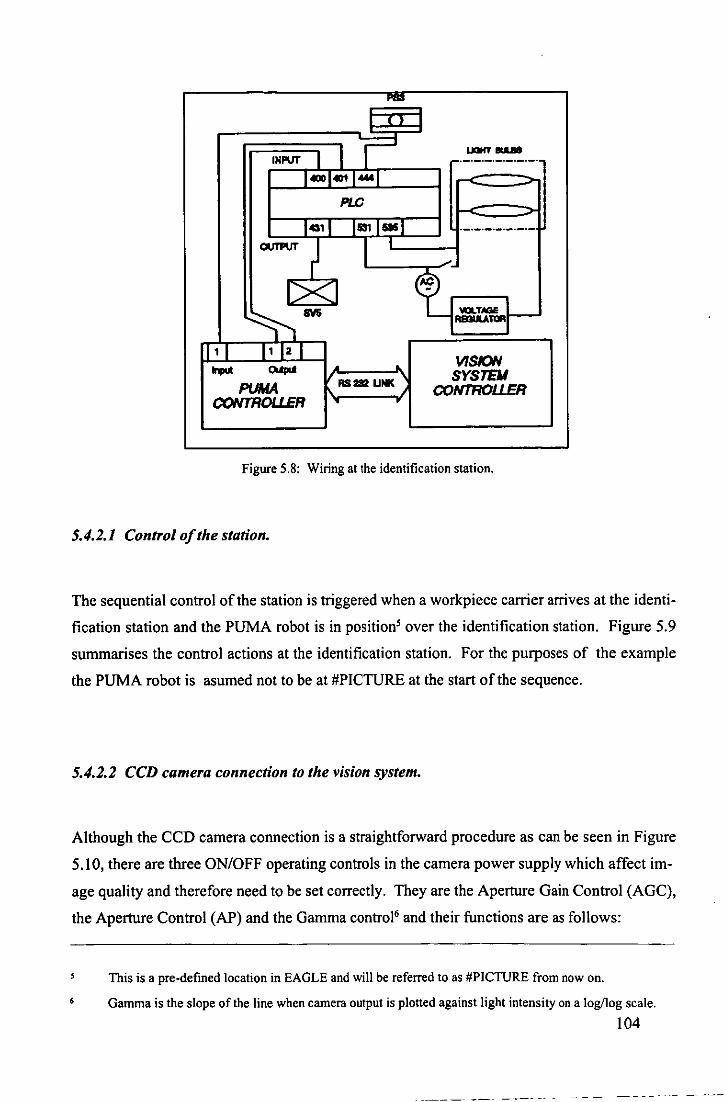
...... I
tNPIIf 1 II' ...,. ... r-'-'-'-'-'-'-'-'
14001401 1_1 PLC
1011 1531 I-I ._._._._._._.-OUTPIJTJ I -' r
t=!~f--1><1 ~aw
I' 1 I' 12 1 VISION ..... Wpd • ~
SYSTEJI PUMA ASS UNK CONTROUER
CONTROUER .. •
Figure 5.8: Wiring at the identification station.
5.4.2.1 Control o/the station.
The sequential control of the station is triggered when a workpiece carrier arrives at the identi
fication station and the PUMA robot is in positionS over the identification station. Figure 5.9
summarises the control actions at the identification station. For the purposes of the example
the PUMA robot is asumed not to be at #PICTURE at the start of the sequence.
5.4.2.2 CCD camera connection to the vision system.
Although the CCD camera connection is a straightforward procedure as can be seen in Figure
5.10, there are three ON/OFF operating controls in the camera power supply which affect im
age quality and therefore need to be set correctly. They are the Aperture Gain Control (AGC),
the Aperture Control (AP) and the Gamma control" and their functions are as follows:
, This is a pre-defined location in EAGLE and will be referred to as #PICTURE from now on.
Gamma is the slope of the line when camera output is plotted against light intensity on a log/log scale.
104
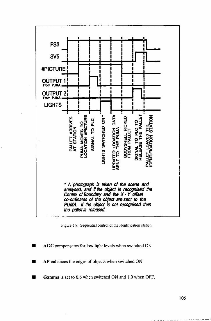
• • • . :
PS3 i i i i i i. r.....!~i 1 __ - i i i i i
SV5 i i i i i •• : il !I • i i • i il 11
-t~·--~~:;~~t--·r #PICTURE i i i !
-t--I .• 1--+-+--: i nil i·· OUTPUT1i i i! i
Fram PUMA -11--+--1
OUTPUT2i i i i ni Fram PUMA -tl -11r-"1--;:1 =:t-;I-;. I.j!~--LIGHTS i i I. i i i
!! . !:! • Z o C w
i ~ Cl :J
Iii ~ ~~ w~ o 11. ~ t;; ~w VI
11. J: U) Z
~~ ~~
~I i~ Il.Q
• A photograph Is taken of the scene and analysed, and If the object Is reoognlsed the Centre of Boundsry and the X· Y offset co-ordinates of the object BI8 sent to the PUMA. If the object Is not recognised then the psJlet is released.
Figure 5.9: Sequential control of the identification station.
• AGe compensates for low light levels when switched ON
• AP enhances the edges of objects when switched ON
• Gamma is set to 0.6 when switched ON and 1.0 when OFF.
105
---------- --- ~-+

To detennine the correct setting of these controls a simple experiment was carried out using the
edge and feature detection factors of the vision system and a range of body shells of different
CAMERA HD __
""" ,.--.--..... CD CO D q.i---oa;;.-,
PUMA ROBOT ARM
,-"' ... -_._--- .-~ ..
//~GC AP GAMMA",·,
\Cllc:.c.) '...... on cif on cif on aft ,/
'''''' ... ' ............... - ... __ .•. __ ............. ..
IMAGE PROCESSING
Figure 5.10: The CCD camera connections and control settings.
colours. The edge and feature detection factors detennine the maximum and minimum thresh
old values used to transfonn grey images into binary. As the names suggest the edge detection
factor picks out the outer boundary of an object and the feature the internal features within that
boundary.
The experiment consisted of finding the best combination of switch settings that would keep
the edge and feature detection factors constant for as large a range of different colour bodyshells
as possible. This experiment was repeated with different levels of illumination to ensure that
the best overall level of compromise was achieved.
It is extremely important to be able to keep the edge and feature detection factors constant as it
allows for accommodating a considerable number of different models in each library7. The best
combination of the ON/OFF switch settings is shown in Figure 5.10.
5.4.3 Decorating station.
The main requirement of this station was the interaction between the PUMA robot and the pad
In the context of computer vision, a library is a file which contains statistical data of the objects within that
file.
106
------------ --_.

printing machine. The required sequence of events was:
• when the robot was not positioned at the printing machine, it would always be in
the sweep cycle
• when the robot is ready to position the matrix in front of the printing machine, the
sweep cycle would be stopped with the arm to the back of the machine
• one print cycle would then be activated and when finished the robot would move
the matrix away
• the sweep cycle would be restarted.
Initially the print cycle would be manually selected from the 28 programmes stored in an
EPROM on the control board in the printing machine.
One possible way to achieve the interaction between the robot and printing machine would
have been to modify this control board, but after consultation with the manufacturer this solu
tion was ruled out. The only solution left was to mimic the required switches on the printing
machine in software using the VO ports on the PUMA controller. Figure 5.11 shows the con
nections for one switch while Table 5.3 lists the switches on the printing machine and the VO
port number on the PUMA controller.
During the initial trials of the robot/printing machine interface a problem was experienced with
the timing between them. A typical example was that the printing machine would not stop
when requested to do so by the software. A consequence of this was that there would often be
a contact between the pads and the matrixlbodyshell before it was positioned correctly.
When the printing machine was being manually operated this problem of not stopping instantly
was also apparent. The problem was found to be that as the doctor blade/spatula carrier is
driven by an air cylinder the on-board electronics would not stop it after the 'stop' signal was
received before it got to one of the limit switches. The probability of the software activating the
stop signal when the arm was touching one of the limit switches was very low.
107

PUMA • •
VO Circuitry ! i -:HJ i i
PRINTING MACHINE
TolnemaJ ClrcuItryC==O>
A l! _.J. r: i:..- -1 --L..-fIJu 1 i i '-________ ...ll-.! _-<A).! -J--..4o---
• l'
SOFTWARE CONTROL
B i i i i i i ! !
MANUAL CONTROL
Figure 5.11: The wiring connections between the PUMA controller and the printing machine.
Table 5.3: The printing machine switches controlled by the PUMA controller.
PRINTING MACHINE
SWITCH
Start Switch
Pad stroke
Programme selector
Stop Switch
110 NUMBER
8
9
10
I
The solution to this problem was to duplicate the limit switches and fit an extra switch over the
print position so that the position of the doctor blade/spatula carrier could be monitored. This
way the stop signal could be maintained until the carrier had come to rest.
108

5.4.4 Inspection station.
The control requirements of this station are:
• connectin of the camera to vision system
• interaction with the PUMA robot for selecting the various parts of the bodyshell to
be inspected
• communication with the unloading station.
5.4.4.1 Camera connections.
Because the same vision system is used by the identification station, the realisation of this
camera connection was simple. It was decided that all the movements to inspect the three areas
of the bodyshell should be carried out by the robot, therefore cheaper but less robust tube cam
eras could be used. Another advantage is that they do not need special power supplies as do
CCD cameras.
5.4.4.2. Interaction with the PUMA robot.
At the inspection station, the movements of the PUMA robot are carried out under the supervi
sion of the vision system. For example, after analysing the first area of the bodyshell, the vision
system will send data to the PUMA controller to tell it to either move the bodyshell to the next
location if it has passed the first inspection or to had it to the RTX robot if it has failed. The
PUMA controller will send data back to the vision system to say that the movement has been
completed.
All communication is via the RS-232C serial links.
109

5.4.4.3 Communication with the unloading station.
The result of the inspection routine, (pass) or (fail), is sent to the unloading station via the RS-
232c serial link. This is done via the PUMA control1er i.e. the vision system sends the data to
the PUMA control1er which in turn transmits the data to the RTX controller at the unloading
station. The reason for this rather tortuous route is that there was only one serial port supplied
with the vision system and no way to fit another.
5.5 UNLOADING STATION.
There are only two requirements at this station:
• interaction between the PUMA and RTX robots
• control of the suction cups on the RTX robot end-effector
5.5.1 Interaction between the PUMA and RTX robots.
Signals are necessary to synchronise the movements of the RTX and PUMA robots as there
workspaces overlap. For instance it is necessary to ensure that the RTX robot would not move
from its grasp position until the PUMA robot had left the unloading station (ROBOT _TRAFFIC
Figure 4.7). Again this is transmitted via the serial1ink between the two control1ers.
5.5.2 Control o/the suction cups ..
This control is executed via the PLC since the only control needed is that of the SV,s linked to
the suction cups. Initial1y only one SV was used to control all five suction cups of the RTX
robot end-effector. This worked wel1 when picking up the pal1etising trays as all five suction
cups were used. However, when just the central one was used to grasp the bodyshell there was
insufficient vacuum generated as the air leakage from the four outer cups caused the air pres
sure to the central cup to drop.
110

The solution to this problem was to use two independent SV's, one to control the outer four to
lift the pallets and one to grasp the bodyshells. Figure 5.12 shows the necessary linksto operate
the unloading station.
RlX CONTROUER
1 2
RTlCground
PLC +2IN
PLC
RS232 UNK
Figure 5.12: Wiring of the unloading station.
VISION SYSTEM
SV10
SV11
Opto couplers were used in the interface between the RTX controller and the PLC to isolate the
RTX controller from the 'high' voltages associated with the PLC. No such interface was re
quired between the PUMA controller and the PLC as they both work at the same voltage of
+24V.
III

CHAPTER 6:
THE OPERATION OF THE CELL.
112

6.1 SUMMARY
Chapters 3, 4 and 5 presented the design of the proof-of-concept-cell through the component
parts of each station. The Mechatronic design methodology used has ensured integration of
each station into the whole; this is highlighted in the operation cycle of the cell described in
Section 6.3.
The operator interface is described in the start up procedure of the cell. A knowledge based
system is being developed to hold the relevant information about the cell operation and it is
envisaged that this will be able to be used by an operator in the form of a consultation session as
well as acting as the overall cell controller.
A relatively simple cell control philosophy with embedded recovery strategies is described in
Section 6.4.
The flexibility of the decoration cell is discussed in Section 6.5 along with possibilities for a
modular cell.
6.2 OVERVIEW OF THE OPERATION OF THE CELL.
A schematic layout of the proof-of-concept cell is shown in Figure 6.1. All the items except the
moulding machine are installed at the Department of Mechanical Engineering and are opera
tional. It is important to mention that to fully decorate the model being used to develop the
proof-of-concept cell seven Tampo printing machines would be required for a flow-line opera
tion. Obviously Homby Hobbies could not spare this number of machines so only one is actu
ally installed in the cell.
6.2.1 Work cycle.
The work cycle of the proof-of-concept cell is described following the various stages through
which an undecorated bodyshell goes through: after leaving the moulding machine the
113
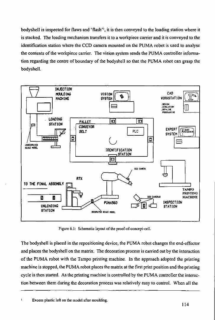
bodyshell is inspected for flaws and' flash ", it is then conveyed to the loading station where it
is stacked. The loading mechanism transfers it to a workpiece carrier and it is conveyed to the
identification station where the CCD camera mounted on the PUMA robot is used to analyse
the contents of the workpiece carrier. The vision system sends the PUMA controller informa
tion regarding the centre of boundary of the bodyshell so that the PUMA robot can grasp the
bodyshell.
IN"(CTIOH rnt.OIN' PfAOllHE
D LOAOI~
STATION
TO THE FINAL ASSEHBlY
III III UNLOADIHG STATION
~ r=-
PAUET CONVEYOR BELT
RTX
UISl~OHA SYSTE/1 ~
E3
L ir!!I IQ
0 G ~ F
10EHTlF ICA TlON ...---. STATION L[]J "--'
PUPfA360
Figure 6.1: Schematic layout of the proof-of-concept-cell.
CAD VORKSTATlON .1D1~ .SUII_ATlOH .Cff'oolUI[ PIIOCAAIV'IltlC
El
IHSPECTlON STATION
00 ill
TAMPO PRINTING MACIllNE
The bodyshell is placed in the repositioning device, the PUMA robot changes the end-effector
and places the bodyshell on the matrix. The decoration process is carried out by the interaction
of the PUMA robot with the Tampo printing machine. In the approach adopted the printing
machine is stopped, the PUMA robot places the matrix at the first print position and the printing
cycle is then started. As the printing machine is controlled by the PUMA controller the interac
tion between them during the decoration process was relatively easy to control. When all the
Excess plastic left on the model after mOUlding. 114
decorations at the first machine are finished the PUMA robot moves to the second machine and
so on.
When all the decorations are completed the PUMA robot transfers the matrix to the inspection
station and the bodyshell is inspected. Finally the bodyshell is handed to the unloading station
where the RTX robot will palletise the bodyshell if it has been accepted by the inspection
routine or place it in a reject bin for possible rework or scrap.
6.3 OPERATION OF THE CELL.
6.3.1 Start up procedure.
Section 6.2 described the on-line operation of the cell, this section describes the requirements
of an operator to initialise the work cycle of the cell. This requirement will be referred to as the
start up procedure from now on. For the purposes of this description it is assumed that the
printing machine had already been set up and the identification and inspection databases gener
ated. It is described as follows:
First the operator switches on the mains electricity supply to the following;
• PUMA controller and PUMA robot
• RTX controller and RTX robot
• Tampo printing machine
• conveyor system motors
• vision system controller and cameras
• PLC and associated power supply
115

• Voltage regulator' of the inspection station.
Next the air supplies to the various parts of the cell have to be connected and the pressures set
according to the values shown in Table 6.1.
Table 6.1: Air supply pressure to the component parts of the proof-of-concept cell.
CELL COMPONENT
Printing machine
Conveyor system
PUMA robot
RTX robot
PRESSURE (bar)
6
4
3
6
If required, the operator will first run the calibration routines to set the PUMA-vision calibra
tion factors and then execute the programme EAGLE. EAGLE controls the actions of the
PUMA robot at the identification, decoration, inspection and unloading stations as described in
Chapter 4. However it also contains the sequential control of the whole proof-of-concept cell.
This will be described in Section 6.4.
Next, the programme EAGLE prompts the operator to run OWL which controls the vision
system. The initial interaction between the two programmes is to check the RS-232 link be
tween the two computers, this is shown diagrammatically in Figure 6.2., if this check is suc
cessful the operator is then prompted to run PUFFIN which controls the RTX robot. As with
OWL, the initial operation of PUFFIN is to check the RS-232 link with the PUMA controller.
This is carried out in exactly the same way as for the vision systemlPUMA controller and if
successful the RTX robot will be calibrated via the built in initialisation routine and then be
driven to the 'safe' location ABOVE]UMA (Figure 4.7) from where it will take the bodyshells
from the PUMA robot.
The regulator voltage is set during the training process. 116

OWL
RS232 UNK
n - 0 v - 100 check - 0
send v
check - check + v
N
N
Figure 6.2: PUMA-vision system RS-232 check.
EAGLE
n - n + 1
halt
EAGLE then prompts the operator to switch on the conveyor system motors, the printing ma
chine and the cameras and monitor. Finally the operator is prompted to select the model to be
decorated. This is done via EAGLE and this information is sent to OWL so that the relevant
database of model information can be loaded for the identification and inspection routines to
use.
Beyond this the operator has no further control as the PUMA controller takes over the sequen
tial running of the cell. The PLC is switched on, the printing machine is operated in 'sweep'
mode and OWL is run up to the point where it waits for the PUMA robot to get to location
#PICTUREJ and a workpiece carrier to arrive at the identification station. The programme
PUFFIN drives the RTX robot to remove the top pallet from the 'empty' stack and place it at
the palletisation position and then return to the safe location ABOVE_PUMA. The on-line
The location in the identification station above the workpiece carrier.
117

operation described in Section 6.2 then takes place.
After executing the start up procedure of the cell a number of times the operator will become
familiar with the sequence of events to be followed. It was felt, however, that some form of aid
would be helpful especially with operators unfamiliar with the cell. This could simply have
taken the form of an operators manual with all the various settings listed, but unless this was
written very carefully it could become extremely difficult to follow. The approach adopted,
however, was to develop a knowledge base which contains all the information relevant to the
operation of the cell. This could be used in the form of a consultation by the operator and the
information supplied graphically on a computer screen.
The expert system Savoir {Intelligent Systems, 1987} is being used for this purpose. This
application, along with other future developments of the cell will be described in Chapter 7.
6.3.2 Operator interface.
The largest part of the interaction between the operator and the decoration cell takes place in
the start up procedure described above. During the on-line period of operation, operator inter
vention will only be required during 'emergency' or non-programmed conditions. The reason
for the emergency may be an irregularity in the decoration cell that is potentially damaging to
the equipment in the cell.
Such an irregularity might be that a bodyshell has not fitted onto the matrix properly. This
could cause problems at the Tampo printing machine during the printing cycle. In this case the
operator would need to interrupt the operational cycle of the cell until the situation was correct
ed. This can be achieved by one ofthe following means:
• Putting the PUMA controller into PAUSE. This will only stop the motion of the
robot and not affect any other function in the programme.
• Individual emergency stop switches (also known as panic switches) located at the
component parts of the cell.
118

• Global emergency stop switch which halts the operation of the whole cell except
the conveyor system. This is linked to an interrupt routine in EAGLE which will
bring the cell to a stop in an orderly and controlled fashion.
6.4 CONTROL OF THE CELL.
The cell controller is EAGLE, a programme written in V AL 11 on the PUMA controller. The
PLC handles all the operations relating to the conveyor system and the loading station, and the
vision system and the RTX robot have their own controllers, but the cell controller can over
ride them whenever necessary. This also applies to the PUMA controller itself, i.e. a task being
executed by the PUMA might be interrupted by the cell controller even though the source of
both is the PUMA controller. This is possible because of the different levels of interrupt calls
from the V AL 11 language. A V AL 11 interrupt has the following structure:
REACT <signal>, <routine>,<priority>
Priority defines the hierarchy level of the routine between the minimum and maximum limits of
1 and 127. When a programme is written it is assigned the default level of I. Suppose that a
programme has the following line in it:
REACT 1010, shutdown, 127
In parallel with the execution of the main programme the robot controller constantly monitors
signal 10\0. When it goes high the controller interrupts the execution of the main programme
(priority normally 1 or any sub-routine or interrupt with a priority level less than 127) and
executes the sub-routine shutdown. When the execution of this programme is finished the
PUMA controller resumes the execution of the interrupted programme.
6.4.1 Recovery strategies_
In order to achieve as Iowa level of human intervention as possible in the decoration process,
the control programme has embedded recovery strategies which are triggered as soon as sen-
119

SOTS indicate that a non desired sequence has taken place. Some researchers would call this an
error recovery strategy; the author, however, prefers to avoid the word error. It is believed that
if one can actually plan to sense an error and recover from it, then it is not an error at all
{Trabasso et aI, 1990b}. These are simply events in a plan and are referred to as deviation
events from now on. The events that lead to the desired event are referred to as goal events. At
the loading station, for example, the goal event is to take a bodyshell from the loading chute
and place it on a workpiece carrier. A possible deviation event is ifthe bodyshell is dropped
before it reaches the workpiece carrier.
The recovery strategy presently adopted is to embed sensing steps and conditionals into the
control programmes. Even though this strategy can be regarded as an ad hoc one it was chosen
because the task of identifying possible deviation events in the decoration process produced a
significant number of situations from which the control programmes could actually recover.
The framework of the recovery strategy is described as follows: each station has sensors to
indicate the presence of deviation events. These sensors are referred to as deviation sensors in
order to differentiate them from the rest of the sensors used in the cell. At some stations the
deviation sensors have a physical configuration, for example the opto switch in the loading
station (Figure 5.5), while at others it is a piece of software as will be described later.
An example of recovery action is given below. It is taken from the loading station shown in
Figure 6.3. Note the deviation sensor attached to cylinder A, this is the opto switch described in
Chapter 5.4.1.2. Suppose that the loading mechanism is holding a bodyshell in position PI. In
this case the output of the deviation sensor (OS) is TRUE. The recovery programme acknowl
edges that OS should stay TRUE until the mechanism gets to point P l' where the bodyshell is
loaded onto the workpiece carrier.
If the bodyshell is dropped before reaching point P 1 the OS output will read FALSE and trigger
an alarm to the control programme. The control programme will release the workpiece carrier
and try to identify the cause of the problem by seeking answers to the following questions:
a) is it a global air failure of the decoration cell?
b) is it a local air failure at the loading station?
120

c) is it a mechanism failure?
If the answers to (a) or (b) are TRUE the software will trigger an alarm to call for mai!1tenance
as this is an example of a true error, an error that the programme cannot recover from. If on the
other hand the answers to (a) and (b) are FALSE the programme can conclude that (c) is TRUE
and will drive the mechanism to the rest position and restart the loading cycle. I f the error
Figure 6.3: Recovery action at the loading station.
recurs then the software will call for assistance from the operator. Simple rules such as this can
be easily drawn for all stages of the decoration process.
It was mentioned that some DS do not have a physical configuration, rather they are pieces of
software. This is the case at the decoration station. The operation of positioning the matrix at
the printing machine by the PUMA robot is essentially that of putting a peg in a hole as shown
in Figure 6.4.
When the robot starts moving from P, to P l' a subroutine samples the distance d, at time t,. At
time t,+. the distance d,+. is also sampled and compared with d,. If d, is equal to d,+. the
subroutine notes that the arm did not move between the two time intervals, for example because
of contact between points P 3 and p., and immediately takes the recovery action of moving the
arm back to position P " In this case this first step has to be taken before the inbuilt firmware
routines are triggered, otherwise the PUMA controller could trigger one of its fatal error rou
tines bringing the cell to a halt in an indeterminate manner. Only after this initial action does 121

~ P1 AT ti
P1 T pit!< ~ r-e- ~
0- LOCATN; fQ.E ~ i', /' '\.
, , , - pj , J \ d ------'-. _______ J ... ------- "
" ,
P2 dit!< ------:----, ,-+-1. P4 , , • , , , , , , , , , , , , , , , , , , , " ,
ti tit!< TIoE
Figure 6.4: Recovery action at the decoration station.
the subroutine inform the main programme of its status so that complementary recovery action
can take place.
The most likely reason for contact between points P 3 and p. is positional tolerance of the robot,
rather than relative movement of the robot or printing machine bases. The recovery programme
directs the robot to repeat the operation keeping the original locations for P, and P z, if there is
another failure the recovery programme redefines P Z' within pre-defined limits, and directs the
robot to try again. A third failure and the programme will signal that there is an error beyond its
recovery capabilities and it will halt the current operation until the problem has been overcome.
Devices such as those just described, who purpose is error free operation, are perfect examples
of what the Japanese term 'poka-yoke'. Poka-yoke translates into 'mistake-proof. Shingo
{ 1986} describes many examples of such devices and systems. The design of these devices is
a perfect example of simple and effective Mechatronics.
122

6.5 FLEXIBILITY OF THE CELL.
Scale model decoration is a process which demands great flexibility in production. This is
because sponsors names, numbers and colour schemes are frequently changed from one season
to the next. One bodyshell can, therefore, have many different sets of decorations. There is
also the possibility of customised decorations should a customer request these. The present
factory based method is fairly flexible but the time required to bring a printing machine 'on
line' for a new decoration outweighs this flexibility.
The problem of making the decoration cell flexible was tackled though its design: flexibility is
embedded in the Mechatronics approach to design. The result can easily be assessed by look
ing at the stations of the cell. All but the decoration station can be easily and quickly re
programmed to execute a new decoration. No special jigs were used so that much of the cell
hardware remains unchanged when a different decoration or bodyshell is required. The major
ity of the modifications are in software: generating the new databases for the identification and
inspection stations and re-teaching the robot locations at the printing machine.
In order to gain a clearer picture of the cell flexibility the scenario of a complete cell changeover
to decorate a different bodyshell with different decorations is described. The following altera
tions to the decoration cell have to be carried out:
i) AT THE LOADING STATION
L I) Change the loading chute,
L2) Vertical adjustment of the handling mechanism.
ii) AT THE IDENTIFICATION STATION
ID I) Generate the pattern recognition database,
ID2) Change the matrix end-effector of the PUMA robot,
ID3) Teach the new matrix locations the PUMA robot.
iiI) AT THE DECORATION STATION
D I) Set up the printing machines,
D2) Teach the new print locations to the PUMA robot.
123
iv) AT THE INSPECTION STATION
IN I) Generate the inspection database for the model,
1N2) Adjust the cameras.
v) AT THE UNLOADING STATION
U I) Change the pallets,
U2) Teach the palletising locations to the RTX robot.
With reference to Chapter 3.3 it will be recalled that the time required for setting up a printing
machine is approximately 3 hours for each model or decoration change. This unfortunately
means that item D I prevents any attempt at a quick cell changeover. All the other items can be
carried out quickly and the database generation can even be carried out off-line if need be.
Using the simulation package GRASP the robot programming can also be carried out off-line,
although there will always be some 'fine tuning' to be finalised on-line.
All these will only make sense, however, if a workable solution is found to item D 1. In other
words if the cell has to shut down for three hours while the printing machine is set up then there
is plenty oftime to carry out the other operations in parallel with this setting up.
6.5.1 Modular decoration station.
One way to speed up the decoration cell changeover would be to have the decoration station as
a detachable module {Trabasso et ai, 1991 d}. Suppose that the cell is nearing the end of the
batch for a particular model. At this time the printing machine or machines for the next batch
could start to be set up so that when the first batch is finished those'machines are removed from
the cell and the new set plugged into it. In this approach the off-line programming of the robots
does make sense, as the new locations could be taught at the same time that the cell is working
on the present model.
124

CHAPTER 7:
AREAS FOR FURTHER RESEARCH
BALANCED CONFIGURATION DESIGN
APPRIMA • THE NEXT GENERATION OF PAD PRINTING MACHINE
125

7.1 SUMMARY
This chapter deals with those topics and ideas that have developed 'from the Mechatronic ap
proach to the design of the proof-of-concept celL
It will not be, as the title may suggest, a list of vague ideas, but descriptions of positive im
provements to the decoration celL Some of these are already in the prototype stage while others
have received considerable attention and thought. Others are operational but not yet linked into
the decoration cell, as is the case with the start up procedure implemented in SA VOIR.
Some of the techniques developed are leading to other related areas such as assembly and also
into unrelated areas such as surgery.
The final part of this chapter deals with a new research proposal, currently before the DTI and
SERC, for the next generation of pad printing machine.
7.2 POSSIBLE IMPROVEMENTS TO THE PRINTING METHOD.
This section will deal with those ideas that have been assessed as worthy of further investiga
tion or have received detailed examination and lead onto other possible techniques.
7.2.1 The PAINTER approach.
Main characteristic: matrix stationary and pads manipulated by the robot.
As shown schematically in Figure 7.1, by taking the matrix away from the pad printing ma
chine and placing it on a raised stand enables the robot to get to all five sides of the bodyshell.
Removing the printing mechanism from the pad printer allows the robot access to the cliche
giving greater freedom in movement and placement, in that it is now no longer necessary for
the bodyshell to be moved every time a new area has to be decorated. This idea has been taken
a stage further in that by placing several pads on one holder the robot is able to decorate all the
sides of the bodyshell in one continuous movement {Trabasso et ai, I 990d} .
126

,"IDE AOO
NJ.JJST POSITION
Figure 7.1: Schematic of the PAINTER approach.
ClItOCS
KlOCL "",TRIl
To ensure the accurate placement of the decorations on the bodyshell, it was found to be neces
sary to provide some form of guiding device for the robot. The method chosen was to fit a
guide bar to the front face of the mechanism and have this interact with an adjustable docking
mechanism fitted to the base of the stand, so allowing one stand to be used for any bodyshell.
As a further development the docking mechanism could be adjusted automatically as part of the
set up procedure of the cell.
A prototype was built and successfully tested in that the robot could get to all the sides of the
bodyshell. For instance, to decorate the two sides and the roof it was only necessary to describe
a circular path centred in the middle of the matrix to move the robot round the bodyshell, and
then use straight line motion to bring the pad into contact with the bodyshell. There are howev
er two main drawbacks to this approach. They are:
i) Drying time of the ink: the depth of the etch in the cliche is very small, usually 0.02
millimetres, consequently the ink tends to dry in around 5 seconds. This is one of the reasons
why 'wet-on-wet' operations are possible in pad printing. By the time the robot has picked up
all the decorations and transferred the pads to the bodyshell the ink is already nearly dry, mak-
127
--- ------ --_._------
ing successful transfer nearly impossible. The movement of the pads through the air only adds
to the problem.
ii) Placement of locating devices on the printing machine: the same requirement for high
precision (0.01 millimetres) at the printing machine makes it necessary to have a similar dock
ing mechanism to that at the print position. This docking mechanism would have to be retract
able so that the doctor blade mechanism could wipe the cliche.
There is a potential solution to the first problem in that modification to the ink consistency or
composition could increase the drying time. The second problem is more complex however,
with no clear solution as yet. The main difficulty is that there is very little room on a standard
printing machine to fit this sort of modification.
A scenario where this technology could be made to work is if all the decorations of the same
colour for a particular bodyshell were on one cliche in pre-defined areas then the extra size of
the printing machine could allow for the fitting of the necessary retractable guide units.
7.2.2 The peg-in-a-hole approach.
Main characteristic: pads attached to the print machine and the matrix manipulated by the
robot.
In order to overcome problem (ii) above, another decoration approach was devised. In this
approach the decorations are transferred to the silicone pads in the normal manner. After com
pleting this sequence the printing machine holds the pads at the front of the machine in a fixed
location, and the robot pushes the matrixfbodyshell against the pads. Figure 7.2 shows the
principle of operation of this approach.
The location between the two parts is by rods on the printing machine and holes on the matrix
holder, so that the decoration operation can be dealt with as the classic robot task of inserting a
peg in a hole {Trabasso et ai, 1989}.
128
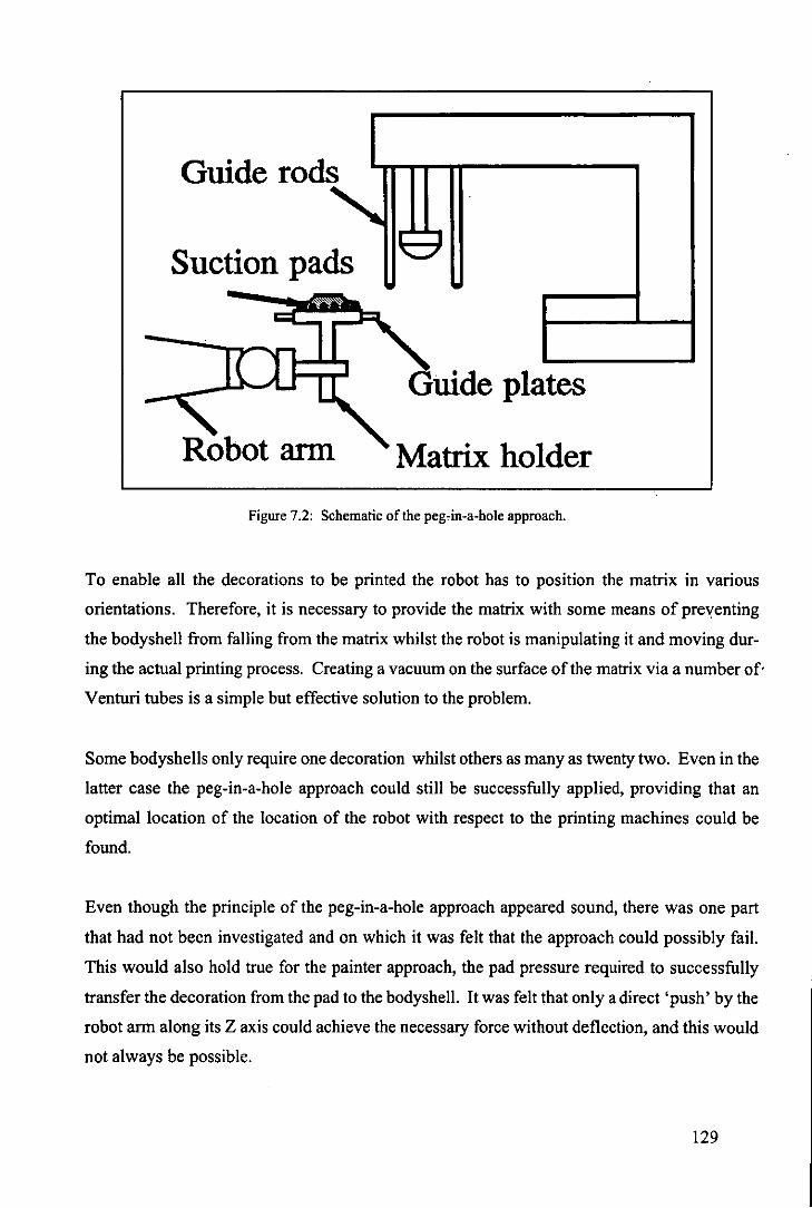
Guide rods
Suction pads
plates
Robot arm Matrix holder
Figure 7.2: Schematic of the peg,in-a-hole approach.
To enable all the decorations to be printed the robot has to position the matrix in various
orientations. Therefore, it is necessary to provide the matrix with some means of pre"enting
the bodyshell from falling from the matrix whilst the robot is manipulating it and moving dur
ing the actual printing process. Creating a vacuum on the surface of the matrix via a number of·
Venturi tubes is a simple but effective solution to the problem.
Some bodyshells only require one decoration whilst others as many as twenty two. Even in the
latter case the peg-in-a-hole approach could still be successfully applied, providing that an
optimal location of the location of the robot with respect to the printing machines could be
found.
Even though the principle of the peg-in-a-hole approach appeared sound, there was one part
that had not been investigated and on which it was felt that the approach could possibly fail.
This would also hold true for the painter approach, the pad pressure required to successfully
transfer the decoration from the pad to the bodyshell. It was felt that only a direct 'push' by the
robot arm along its Z axis could achieve the necessary force without deflection, and this would
not always be possible.
129

This doubt led to the adoption of the actual approach used in the decoration cell. This is de
scribed below.
7.2.3 The revised peg-in-a-hole approach.
Main characteristic: pads attached to the printing machine and the matrix manipulated by
the robot, and locating pegs attached to the worktable of the printing
machine.
The main problem with the original version was the setting up of the printing machine. In order
to test the print location and quality on the bodyshell the technician would also have to operate
the robot which would make getting to the front of the printing machine to check the operation
very difficult. To overcome this problem the locating pegs of the guiding device were trans-
Figure 7.3: The revised peg-in-a-hole approach.
ferred from the original position on the printing machine to blocks attached to the worktable in
front of the printing machine, and the guide holes to the bottom of the matrix unit {Trabasso et
al,199Ic} as shown in Figure 7.3.
130
.'

The advantage of this method is that no force need be exerted by the robot nor is any exerted on'
it. This method does not require the technician to carry out any further operations than at present,
as he has to fit the matrices to the worktable in front of the printing machine in the current
factory method. There were two problems to this approach, though, in that it is not always
possible to present a horizontal surface to the printing pads and there was no adjustment in the
X- Yplane.
To overcome this a new adjustable baseplate was designed (Figure 7.4) so that the matrix unit
could be tilted through a maximum angle of 40°1 should this be necessary. The adjustments in
Figure 7.4: Modified peg-in-a-hole base unit.
the X-Yplane are now catered for by slots located in the bottom flange of the base unit and the
angular adjustment by rotating a cam inside the base. .
Another problem to be solved was to devise a method for the robot to position the matrix for all
the possible positions for decoration. For printing the bonnet, roof and back of the car this
presented no problem as it just meant moving along to the next set oflocating holes. The sides
could be done in the same way as all th~t is required is that the robot turns the matrix 90° for one
side and _90° for the other. Obviously for these operations the base is set horizontal.
The difficulty is to print the decorations on the front and rear areas of the bodyshell (Figure 2.4
refers). The first idea was to attach the robot to the base of the matrix as this never decorated,
and whilst this would work for the sides and ends of the bodyshell it presented difficulties for
This angle was arrived at by measuring various bodyshells to check the varation in the inclination of the
bonnet with respect to the roof.
131

the top faces. It was decided to try an al
ternative method.
This new method, shown in Figure 7.5, and
referred to as the indexing matrix, gives the
matrix the capability of rotation through an
axis perpendicular to it. The rotation in
dex for the present design is 90°. The prin- .
ciple as presently designed is purely me-
chanical in that the robot pushes the matrix
against an auxiliary rod and then rotates the
End effector case
.. , ------.., Attached to • , • • , •
Attached to i •
~tri.
end effector
Figure 7.5: The indexing matrix principle
matrix the required number of notches. A mechatronics way would be to use a solenoid or
stepper motor inside the matrix to rotate it relative to the robot end-effector.
7.2.4 Improvements to the revised peg-in-a-hole approach.
To arrive at the conclusion that the previous approach needs yet another improvement, it is
necessary to look at the scenario where a bodyshell receives all the planned decorations. Sup
pose that this requires seven pad printing machines as is the case with the Texaco Sierra.
After printing the bonnet and roof at the first printing machine, for instance, the robot would
move the matrix to the second printing machine to print the sides for example. Meanwhile the
first printing machine is idle as are numbers three to seven. At anyone time only one printing
machine would be working.
The main concern is not the throughput of the cell, because even with this approach the two to
three minutes to produce a fully decorated bodyshell is far better than the present factory time
of two to three weeks. Rather it is that the full potential of the PUMA robot has not been
achieved in this approach. A possible ~olution is the matrix-on-belt approach described below.
7.2.5 The matrix-on-belt approach.
A schematic of the matrix -on-belt approach is shown in Figure 7.6. One of the advantages of
132

this ap-
proach is
that there are
no modifica
tions re
quired to the
printing ma
chine other
than that of
removing
t h e
worktable at
the front and
replacing it
with the ma
trix-on-belt unit.
I;;
Figure 7.6: The principle of operation of the matrix-on·belt approach.
The principle of operation is as follows: the matrix/bodyshell units are loaded at the left hand
side and they are carried across towards the right hand side by a conveyor belt. Stop gates hold
the matrix units in position under the printing pads and they are then lifted up off the conveyor
belt by a pneumatic cylinder which is locked in place. The printing pads then transfer the
decoration to the bodyshell in the usual manner. The cylinder is released and the matrices are
returned to the conveyor belt, the gates are opened and the matrices travel to the next location
and the procedure is repeated.
When the matrix gets to the right hand side it is held in a buffer until it can be transferred to the
next operation which could be further decoration at another printing machine or inspection.
With regard to the setting up operations, the cylinder would be raised and locked in position
and the technician carry out the usual adjustments to the pads and doctor blade. The only extra
job wO\lld be to set the gates on the conveyor belt when he was satisfied with the decoration
position.
To perceive the benefits ofthis method one has to recall the scenario with seven pad printing
133
._- - .. _------------------

machines required to completely decorate the bodyshell. If each of the printing machines was
equipped with matrix-on-belt unit then it is easy to visualise the matrices being loaded at one
end and being transferred from printing machine to printing machine and finally to the inspec
tion station. In the present scenario it is not necessary to employ a PUMA robot as specialised
handling mechanisms could be built for the interchange between each printing machine.
It need not even be necessary to use a robot to transfer from the loading chute to the first
printing machine if the orientation could be guaranteed before hand, it can only be one way
round or the other, so that again a dedicated mechanism similar to the transfer mechanism
Figure 7.7: The model of the prototype matrix-on-belt approach.
could be used here as well.
There is a problem with this approach in that again the model has to change orientation between
printing machines so a modification to the matrix-on-belt idea was adopted and a prototype
model built to test out the theory (Figure 7.7). In this approach a rack is used to rotate the
model about its perpendicular axis and a guiding mechanism to roll it into the horizontal plane.
134

7.2.6 Other modifications to the printing machine.
Another possible beneficial modification to the pad printing machine would be the incorpora
tion of a cleaning mechanism for the pads. This could simply be a piece of sticky tape onto
which the pads are pressed after every printing cycle. This would require the firmware in the
printing machines RAM to be rewritten to facilitate this and an additional 'printing' position
for the pads.
7.3 OTHER PRINTING TECHNOLOGIES.
Before finishing the discussion on improvements to pad printing it is important to mention two
other technologies, ink jet and transfers.
7.3.1 Ink Jet Printing.
A demand for a fast, computer compatible printing method has produced a new technology, ink
jet. The common principle that characterises all the various types of ink jet printing is the
projection of a small, electrically charged ink droplet on to the surface to be printed. The
process is controlled on a drop-by-drop basis in the order of 100,000 droplets per second. Each
droplet is deflected by passing it through an electric field in a similar manner to that employed
in a CRT. Unwanted droplets are deflected into a gutter and pumped back into the main system
to be used again.
Recent advances in ink jet now incorporate arrays of nozzles so that the restriction on printing
using a single nozzle has been removed allowing a greater selection in the size and style of font
that can be used, also graphics can now be produced with much better definition. Unfortunate
ly the technology still exhibits a number of disadvantages which make it unsuitable for fine
decoration. These are;
• because the printing is applied via a finite array of holes, it is essentially a binary
process. Therefore, on the surface being printed each dot is either there or not there
which has the drawback that lines or edges which are not parallel or perpendicular
135
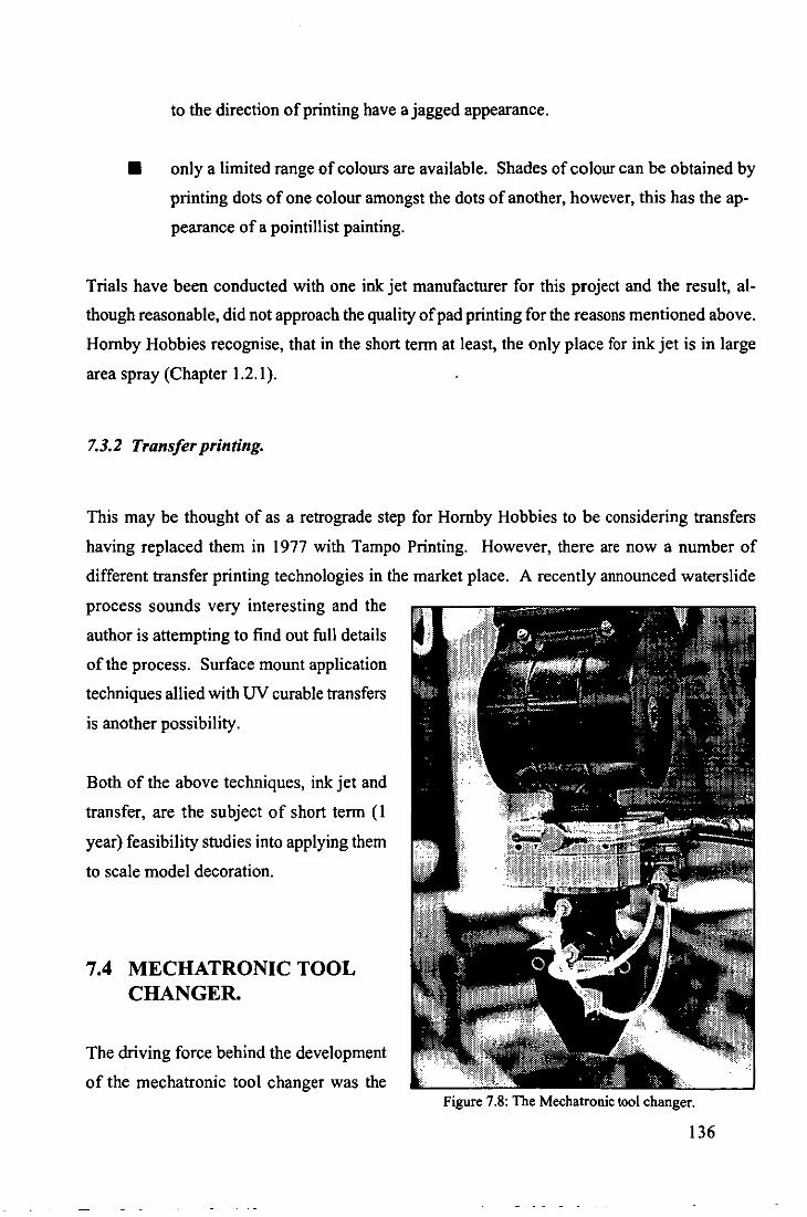
to the direction of printing have a jagged appearance.
• only a limited range of colours are available. Shades of colour can be obtained by
printing dots of one colour amongst the dots of another, however, this has the ap
pearance of a pointillist painting.
Trials have been conducted with one ink jet manufacturer for this project and the result, al
though reasonable, did not approach the quality of pad printing for the reasons mentioned above.
Homby Hobbies recognise, that in the short term at least, the only place for ink jet is in large
area spray (Chapter 1.2.1).
7.3.2 Transfer printing.
This may be thought of as a retrograde step for Homby Hobbies to be considering transfers
having replaced them in 1977 with Tampo Printing. However, there are now a number of
different transfer printing technologies in the market place. A recently announced waterslide
process sounds very interesting and the
author is attempting to find out full details
of the process. Surface mount application
techniques allied with UV curable transfers
is another possibility.
Both of the above techniques, ink jet and
transfer, are the subject of short term (I
year) feasibility studies into applying them
to scale model decoration.
7.4 MECHATRONIC TOOL CHANGER.
The driving force behind the development
of the mechatronic tool changer was the Figure 7.8: The Mechalronic tool changer.
136

difficulties experienced with the present tool changer (Chapter 3.2.4.1). In the beginning the
intention was to develop a tool changer that did not require the PUMA robot to return to a tool
rack for every tool change. Only with this condition satisfied could the original matrix-on-belt
approach be considered as a viable working proposition. After the first test though, it became
apparent that it could be applied to any robotic situation that required a tool changer. It weighs
0.5 Kilograms and can lift 22 Kilograms. A patent is now being sought for it.
7.4.1 The locking and unlocking principle.
The tool changer has active pneumatic locking based on the Venturi principle and active un-
Figure 7.9:' The passive and active locking mechanisms of the mechatronic tool changer.
locking based upon positive air pressure. Passive mechanical locking is also built into the unit
in case of air failure. This is able to withstand a continuous load of 16 Kilograms.
A single venturi device with four outlets with '0' ring seals is built into the robot adaptor
(Figure 7.9), these outlets fit into four cavities in the tool adaptor. To lock the mechanism the
exhaust of the venturi is left open and a vacuum is generated in the cavities pulling the two parts
together. To unlock, the exhaust is blocked so that a positive pressure is generated and the two
parts are blown apart.
137

7.4.2 Pneumatic and electrical ports.
The prototype tool changer is provided with two pneumatic ports, which are not self-sealing,
and six opto-electrical connections which are less susceptible to wear and dirt and electrical
interference than the more usual mechanical connections. Power is transferred between the two
parts of the tool changer by a small jack plug.
7.5 SINGLE AXIS FORCE - ACCELERATION ADAPTOR.
Because it was felt
that some of the
techniques learnt
and applied in the
decoration cell
could equally be
applied to other ap
plications, a start
has been made on
looking at possible
methods of auto
matic assembly of
model car chassis'.
The first area of in
terest is the assem
bly, from the com
ponent parts, of
rear axles and their
fitment into the
chassis. One par
ticular problem is
the actual fitment
of the assembled
axle into the chas- Figure 7.10: The force I acceleration adapter undergoing trials.
138

SIS. This necessitates a 'snap' fit as the axle bearings are pushed into the chassis, Figure 7.10.
AXLE BEARIN~...a
a b FORCE
c a b c ACCELERATION
Figure 7.11: The graphs of force and acceleration for the assembly of an axle into a chassis.
Figure 7.12: Single axis force·acceleration adaptor.
------------
139

To measure this using an ordinary load cell would not allow the operator, or robot, to know if it
was being pushed home correctly or it was jamming. But if you measure acceleration at the
same time then a much more accurate picture of the assembly operation is provided, Figure
7.11.
A simple attachment for the PUMA robot (Figure 7.12) has been designed and is currently
undergoing trials to test its accuracy and repeatability as well as its suitability for single axis
force-acceleration measurement.
7.6 BALANCED CONFIGUATION DESIGN
The natural extension to the decoration project is assembly. The particular problems that
Homby Hobbies experience are in the handling of flexible and unstructured objects, mainly in
the form of the wiring looms used in the cars and trains. The other components are of standard
type but of varying dimensions.
Taking the rear axle assembly as an example of the type of problem experienced with assem
bly. There are 6 different axle lengths, 10 wheel types,S different types of tyre and 15 different
axle bearing centres. With this number of combinations the possibility of producing an item for
rework or scrap is very high indeed.
It would be impracticable to' consider producing a separate item of sensorless automation for
each axle combination. Likewise an universal axle assembly machine would be prohibitively
expensive. As a compromise it is felt that concurrent engineering techniques should be applied
from the design stage so that a sensible balance is achieved between the two.
This approach is referred to as Balanced Configuration Design and an experimental unit has
been constructed to test out these principles (Figure 7.13). It is not totalIy sensorless nor is it
over endowed with sensory feedback. The author feels that if the force/acceleration sensor
described in section 7.6 is used in conjunction with an unit of this type and the assembly/
manufacturing constraints considered at the design stage then this will lead to a reduction in
assembly time and an improvement in product quality.
This idea is the basis of a further research proposal to the S.E.R.C. 140

Figure 7.13: Balanced Configuration Design experimental unit.
7.7 ARTIFICIAL INTELLIGENCE APPLICATIONS.
It was found that some Artificial Intelligence tools could be applied to the robotic decoration
process to improve its performance in certain areas {Trabasso et aI, I 990a }. For an introduction
to Artificial Intelligence applications to Robotics refer to Staugaard Jr. {1987}. Three such
areas are:
• start up of the cell
• assessment of the training process
• recovery strategies
All the applications are to be implemented using the expert system shell SA VOIR as this is
readily available within the Department of Mechanical Engineering.
141

7.7.1 Start up of the Decoration CelL
This tool consists of a programme to aid the operator carry out the start up procedure detailed
above. The more automated this operation becomes the easier it will be for the operator, espe
ciaIly untrained ones. The programme takes the operator through the start up procedure of the
ceIl step by step, asks questions and displays the operational status of the ceIl based on the
answers given. It also provides explanatory notes whenever requested. Figure 7.14 shows a
computer screen with the corresponding graphical output when the reply is given.
The next stage of this application will be to have sensors linked into the variables in the ceIl so
that the responses currently given by the operator will be replaced by readings from the sensors.
7.7.2 Assessment of the training
process.
The success ofthe operation of the
identification station relies mainly
on the training and classification
processes performed by the opera·
tor during new model changeover.
It can easily be shown that a poor
training process will lead to poor
results in the classification rou
tine. Unfortunately the result of
the training process can be differ
ent when performed by different
operators since some of the deci
sions are left to the operator's
judgement: the definition of the
threshold levels to transform a
grey image into a binary image is
one example. Based only on visu
al inspection, the operator has to Figure 7.14: Example of a consultation session by the operator during the start up of the decoration cel1.
142

decide whether the binary image is good enough to represent the object in view. One approach
which is now emerging for tackling this problem is to simulate the data of the training process
on a CAD workstation and then load these synthetic images into the vision system database as
described by Rauber {1989}. There are a number of problems with this method such as:
• the simulation of the lighting conditions
• unexpected reflections and shadows
• the small number of positions of the object.
This has lead to another approach. The training process is left as it is with the same degree of
subjectivity and the knowledge about the training process is stored in an expert system. This is
then used to 'judge' the result of the training process based on information gathered from the
classification process.
The expert system asks the operator to place the model in the field of view of the vision system
and run the classification routines a number of times. After each run the operator inputs the
values of the orientation angle and centre of boundary of the object into the expert system. This
information is then used by the expert system to generate the value to be tested in the function
MEMBER2. Based on the membership test the expert system may ask the operator to repeat the
training process, giving a list of parameters that can be changed in order to improve the result.
7.7.3 Recovery strategies.
The recovery actions are presently built into the various programmes that control the compo
nent parts of the decoration cell. For instance, the recovery action of the loading station is part
of the PLC programme.
2 MEMBER is a fuzzy set function within the SA VOIR shell. It returns the probability that a given value is
in a particular range. If the value is outside pre-set wide bounds MEMBER returns 0.0. if it is within a
narrow bound MEMBER returns 1.0. For values in between MEMBER will return a probability between
0.0 and 1.0 scaled by linear interpolation.
143

The ideal scenario, and one which the author is working towards, is to have all the deviation
sensors linked into a single programme. An ideal programme is an expert system shell which
has the structure for keeping the recovery actions through production rules. A particular input
from the sensors would trigger a corresponding recovery action.
Even though parts of these programmes are being built and tested they are not yet implemented
in the decoration cell.
7.8 APPRlMA - THE NEXT GENERATION OF PAD PRINTING
MACHINE.
The reader may well wonder why the researcher has continued to bring forward new ideas for
modifications to pad printing machines when it is becoming clear that there are still many other
areas to explore. Referring back to Chapter 1.3 he will see that one ofthe constraints imposed
on the project was that it should utilise the existing tampo print machines. For the purpose of
this chapter that constraint does not exist and so a completely fresh look at pad printing has
been possible.
A list of desirable attributes were drawn up and these were as follows:
The new printing machine;
• must be capable of rapid changeover between models,
• must use a closed ink system,
• must be capable of multi-colour printing,
• must be able to decorate a multi-sided article,
• must operate at around the current pad printing speed i.e. in the order of one
cycle per.every three seconds,
144

• should have built in quality control,
• should be 'intelligent' in that it can sense when things are going wrong and be
self correcting,
• should be capable of printing different sized decorations without outside assistance
i.e. it must have the capability of automatic pad change,
• should have the ability for automatic pad cleaning,
• must be easy to operate and set up,
• must be competitive on price.
These ideal features were compared with the present designs of printing machines (Table 7.1)
to see where the differences were between what is available and what would be desirable.
Table 7.1: The comparison of the features incorporated in the different designs of pad printing machine.
Present machine 'Advanced' machine APPRIMA
Fixed cliche Fixed Cliche Adjustable cliche Open ink reservoir Closed ink tubs Closed ink cartridges High precision High precision Medum precision I degree of freedom 2 degree of freedom I degree of freedom,
adjustable Mechanical elements Mechanical elements Sensory feedback
+ encoders via vision Manual loading/unloading Manual loading/unloading Integrated mechanical
handling Human inspection Human inspection Computer based vision Manual switching Stored sequence Fully programmable
with learning £5K £120K £50K
145
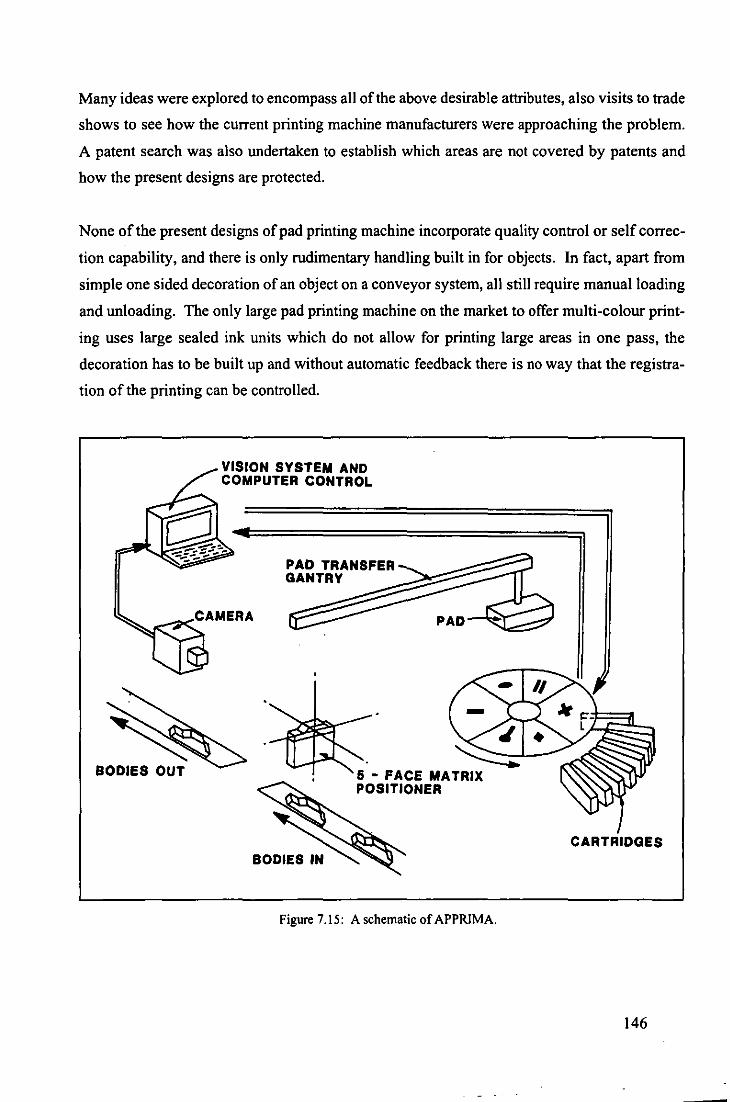
Many ideas were explored to encompass all of the above desirable attributes, also visits to trade
shows to see how the current printing machine manufacturers were approaching the problem.
A patent search was also undertaken to establish which areas are not covered by patents and
how the present designs are protected.
None of the present designs of pad printing machine incorporate quality control or self correc
tion capability, and there is only rudimentary handling built in for objects. In fact, apart from
simple one sided decoration of an object on a conveyor system, all still require manual loading
and unloading. The only large pad printing machine on the market to offer multi-colour print
ing uses large sealed ink units which do not allow for printing large areas in one pass, the
decoration has to be built up and without automatic feedback there is no way that the registra
tion ofthe printing can be controlled.
BODIES OUT
VISION SYSTEM AND COMPUTER CONTROL
PAD TRANSFER GANTRY
J ~..-
5 - FACE MATRIX POSITIONER
Figure 7.15: A schematic of APPRlMA.
CARTRIDGES
146
Figure 7.15 shows a schematic of the APPRIMA' printing machine which is the subject of a
current research proposal to the DTI LINK High Speed Machinery Initiative. The outline
Mechatronic design draws upon the knowledge gained from the present research project to
incorporate all of the above features plus some novel inking and handling mechanisms which,
along with the incorporation of on-line quality control and self calibration/regulation, will form
the basis of the research content of the project.
To give some idea of the perceived success of this project, many of the ideas mentioned above
for tool changing, force sensing and pad printing are being used as start up projects for a com
pletely new venture being undertaken by the Department of Mechanical Engineering at Lough
borough University of Technology. This is MEDUEI4, which is intended as a means of taking
'good' ideas from research projects and producing working marketable prototypes so that they
can then be exploited commercially.
4
Advanced Pad PRInting MAchine for Just-in-Time Production.
MEchatronics Design Unit for the Exploitation ofInvention.
------._-----
147

CHAPTER 8:
CONCLUSION
148
- - - --- -------

8.1 SUMMARY.
The results of this work can be looked at in two different ways: the contribution to scale model
decorating and hence pad printing and the contribution to Mechatronics.
8.2 CONTRIBUTION TO SCALE MODEL DECORATION
AND PAD PRINTING.
The design requirements of the decoration cell stated in Chapter 1.3 can be summarised as
follows:
Design a decoration cell which is capable of fully decorating
any bodyshell manufactured by Hornby Hobbies Limited at
a production rate of 60 bodyshells per hour.
A detailed analysis of the cell flexibility was presented in Chapter 3. This pointed out that the
use of open ink well pad printing machines was the greatest constraint on the flexibility of the
proof-of-concept cell. All but the decoration station can be quickly and easily reconfigured to
execute a new decoration on a different bodyshell. No special jigs were required so that the
bulk of the hardware in the cell remains unchanged after a changeover to a new product. The
majority of the changes are in software.
It is believed that the flexibility requirement was met and that the adoption of closed ink sys
tems, such as those described in Chapter 1.5.3, by Homby Hobbies Limited, would make the
flexibility of the decoration cell more realistic.
Another important requirement was the flow line approach to decorating the bodyshells. In this
proposal the bodyshell is only removed from the matrix after it has been fully decorated. This
is a major improvement on the current factory based method.
Undoubtedly the high quality of the decoration process was maintained through the concept of
the peg-in-hole approach described in Chapter 7.2. Figure 8.1 shows an example of the one of
the first mechatronically decorated bodyshells.
149

Figure 8.1: The first Mechatronicaly decorated bodyshell.
The trial was carried out using just a single colour painting the bonnet and roof in the manner
described in this work. The roof logo should be red and not white. The poor quality of the
decoration on this sample is probably due to one or more of the following reasons:
• lack of experience with the printing technique,
• 'dirty' bodyshell, which had been handled many times and was probably therefore
greasy,
• poor cliche.
It was stated in Chapter 7.2.2 that some form of active restraining device would be required to
prevent the bodyshell from falling from the matrix during movement by the PUMA robot. Be
cause of the shape of the particular car used to prove the decoration cell this was not necessary,
but for most of the other bodyshells this would have proved to be an essential requirement.
Another important contribution to the overall project was the incorporation of on-line quality
control. It is now no longer subjective and inconsistent. 150

Obviously it is only possible to estimate the production rate for the proof-of-concept cell as
only one printing machine was actually linked into it. However, this time could be dramatically
improved by incorporating the ideas outlined in Chapter 7.2, which still maintain the peg-in
hole approach, but explore the full potential of the printing machines.
It is important to note that the decoration cell was designed in such a way that it could be
incorporated into the factory environment. Refer to Figure 6. I. The injection moulding ma
chines are at one end feeding plain bodyshells in and fully decorated palletised bodyshells,
ready for assembly, are presented at the other. When the assembly operation is eventually fully
automated this will be an important requirement, in that the position and orientation of the fully
decorated bodyshells will be already known.
It is believed that the initial design requirements of the decoration process have been met.
Obviously it is not intended that the proof-of-concept cell be simply moved from the laboratory
to Homby Hobbies Limited. However the author believes that much of the work presented here
can be readily incorporated into an automated decoration process when Homby Hobbies Limit
ed choose this route.
8.3 CONTRIBUTION TO MECHATRONICS.
The essence of the work was highly practical: the final result producing one of the few fully
working integrated demonstration cells of its type. Consequently it is not expected to have a
major theoretical impact.
•
Some people claim that there is no need for another discipline such as Mechatronics, as it has
been practised for years, often without the practitioners realising it or being conscious of the
name. One expects, however, to find totally different results when the Mechatronics approach
is used intentionally rather than by accident.
It is difficult to visualise the final configuration of the proof-of-concept cell as a whole ifit had
been designed by techniques other than the Mechatronics approach. However, it is not difficult
to carry out this exercise with two examples of parts of the cell.
151

I) After facing the problems with the reflections when identifying the bodyshells, the solu
tion of using a jig or restraining device to locate the bodyshells seemed to be the only viable
solution even though it was at the expense of flexibility. Opposing this purely mechanical
solution was the side-lighting system, which is an integrated electrical-mechanical solution,
which overcame to problem and maintained the total flexibility of the cell.
2) The re-positioning device is another example in which a simple mechanical solution
solved the problem of optical illusion error that could only be solved otherwise by a very com
plex software route.
These are only examples of cheap, simple and efficient solutions to the overall efficient run
ning of the proof-of-concept cell whose conception was arrived at as a direct result of the
Mechatronics approach to design. Thus it can be said that the decoration cell is a rather good
example of a mechatronic product. The key element of Mechatronics, integration, can readily
be seen when the cell is operating.
Mechatronics must be thought of as a technology that one has to be aware of in order to design
low cost, simple and versatile products.
Having worked on this project, the author acknowledges that he has now acquired the
Mechatronic way of looking at problems i.e. How can he design this product so that he allo
cates the functional requirements between the mechanical, electronic and computing sci
ence environments?
152

REFERENCES
153
- --- ----- - - ------ --

FU, K.S., GONZALES, R.C., LEE, C.S.G. (1987). Robotics: Control. Sensing. Vision and
Intelligence. McGraw-Hill, Singapore.
KA YE, G.W.C. (1973). Tables of Physical and Chemical Constants. pp 91, Van Nostrand
Reinho1d, New York, NY, USA.
JOYCE-LOEBL. (1985). Image Analysis: Principles and Practise. Gateshead, Newcastle
upon-Tyne, U.K.
JOYCE-LOEBL. (1987). Magiscan: Pascal Programmers Guide. Gateshead, Newcastle-upon
Tyne, U.K.
INTELLIGENT SYSTEMS INTERNATIONAL. (1987) The Savoir Expert System Shell: Pro
grammers Guide. Surrey, UK.
MITSUBISHI ELECTRIC CO. (1987). Melsec F1 Series Mitsubishi Programmable Control
ler: Programming Manual. High Function Version, Tokyo, Japan.
RAUBER, T.W. (1989). Generating Synthetic images Using PADL-2. New University of
Lisbon, Department of Robotics, Lisbon, Portugal. (Technical report GR RT -PS-IOC89).
ROACH, S., (1989). Design of an Automatic Tool Changer for the PUMA Robot. Loughbor
ough University of Technology, Department of Mechanical Engineering, Loughborough, U.K.
(Final year project report).
RUOCCO, S.R. (1987). Robot Sensors and Transducers. Open University Press, Milton
Keynes, U.K.
SEYER, M.D. (1984). Rs-232 Made Easy: Connecting Computers. Printers. Terminals and
Modems. Prentice-Hall Inc., NJ. USA.
SHINGO, S. (1986). Mechanical Engineering Design. McGraw-Hill, New York, NY. USA.
STAUGAARD Jr, A. (1987). Robotics and AI: an Introduction to Applied Machine Intelli
gence. Prentice-Hall Inc., Eaglewood Cliffs, NJ. USA. 154
-- --- ----~--- - ---------------

TRABASSO, L.G., HEWIT, J.R., SLADE, A.P. (1989). A Vision Assisted Robotic Decoration
of Scale Models. Proceedings of the 2nd International Conference on Robotics, Dubrovnik,
Yugoslavia, 1989.
TRABASSO, L.G., HEWIT, J.R., SLADE, A.P. (1990a). Artificial intelligence techniques
Applied to the Decoration of Scale Models. Proceedings of the IMechE Conference on
Mechatronics: Designing Intelligent Machines, Cambridge, U.K. pp 165-170, 1990.
TRABASSO, L.G., HEWIT, J.R., SLADE, A.P. (1990b). Decorating Scale Models the Ro
botic Way . Proceedings of the 11th International Conference on Assembly Automation,
Dearborn, Detroit MI, pp83 I : 1-12, 1990.
TRABASSO, L.G., HEWJT, J.R., SLADE, A.P. (l990c). A Vision Assisted Robotic Cell for
Scale Model Decoration. Proceedings of the 28th International Matador Conference, Manches
ter, U.K. pp 35-40, 1990.
TRABASSO, L.G., HEWIT, J.R., SLADE, A.P. (1990d). Robotics applied in the Decoration
of Scale Models. Proceedings of the 8th CISM - IFToMM 'Ro.Man.sy' Conference, Cracow,
Poland, 1990.
TRABASSO, L.G., HEWIT, J.R., SLADE, A.P. (l99Ia). The Education of Mechatronic
Engineers. Proceedings of the International Conference on Computer Aided Engineering Edu
cation. Prague Czechoslovakia, 1991.
TRABASSO, L.G., HEWIT, J.R., SLADE, A.P. (1991b). Intelligent Decoration of Scale Mod
els. Proceedings of the 4th World Conference on Robotics Research. Pittsburgh, PE. 1991.
TRABASSO, L.G., HEWJT, J.R., SLADE, A.P. (l99Ic). Integrating Vision and Robotics to
Assist With Scale Model Decoration. Proceedings ofthe IMechE Conference - Eurotech Direct
'91, Birmingham, UK. paper number C4151052, 1991.
TRABASSO, L.G., HEWJT, J.R., SLADE, A.P. (l99Id). Manufacture of Scale Models With
a New Control Strategy. Proceedings of the IMACS - IFAC Symposium on Modelling and
155

Control of Technological Systems. Lille, France, Voll, pp 621-626,1991.
TRABASSO, L.G., HEWIT, lR., SLADE, A.P. (199Ie). Printing Scale Models Using
Mechatronic Techniques. Mechatronics. Voll number I, pp 95-104,1991.
TRABASSO, L.G., HEWIT, J.R., SLADE, A.P. (199.1 t). Vision Assisted Robotics in the Deco
ration and Assembly of Scale Models. Proceedings of the Eurovision - Imacs Conference,
Corfu, Greece. 1991
TRABASSO, L.G, and ZIELINSKl, C. (1990). Semi-Automatic Calibration Procedure for the
Vision-Robot Interface Applied to Scale Model Decoration. Robotica. (1990).
WALDON, S. and MYSTEL, A. (1988). Multiresolutional Representation of Spatial Knowl
edge in Intelligent Control. Artificial Intelligence in Engineering: Robotics and Processes. Com
putational Mechanics Publications, Southampton, UK.
156