Mechatronics and buoyancy implementation of robotic fish ...
15
295 Mechatronics and buoyancy implementation of robotic fish swimming with modular fin mechanisms K H Low School of Mechanical and Aerospace Engineering, Nanyang Technological University, Singapore, 639798, Singapore. email: [email protected] The manuscript was received on 3 April 2006 and was accepted after revision for publication on 1 November 2006. DOI: 10.1243/09596518JSCE276 Abstract: This paper presents an underwater vehicle mimicking the undulating fins of fish. To mimic the actual flexible fins of real fish, a fin-like mechanism is modelled with a series of connecting linkages. By virtue of a specially designed strip, each link is able to turn and slide with respect to the adjacent link. The driving linkages are used to form a mechanical fin consisting of several fin segments, which are able to produce undulations similar to those produced by the actual fins. Owing to the modular design and the flexible structure of the mechanical fin, it is possible to model different types of fin and to construct various biomimetic robots of fish swimming by fin undulations. On the other hand, a buoyancy tank has been designed and attached to the modular fin mechanisms for the complete fish swimming capability. The workspace of the fin mechanism is derived and applied in locomotion implementation. The mechatronics design and locomotion control of the integrated robotic fish are presented. Some qualitative and workspace observations by experiments with the robotic fish are also shown and discussed. Keywords: biomimetic, robotic fish, modular fin mechanism, undulating-fin motion, buoyancy tank 1 INTRODUCTION emulate the motion of fish have been developed for technological application, using state-of-the-art Marine propulsion and manoeuvring have a long technology, robotics, and an understanding of how history of development and have already reached fish swim. On the other hand, fin-based propulsion a level of maturity. This level is in some aspects systems perform well for both high-speed cruising satisfactory and in other aspects, particularly for and high manoeuvrability in fish, making them good transient motion, rather limiting [1]. Fast fish and models for propulsors of underwater vehicles. cetaceans, on the other hand, move with great agility Biomimetics is an emerging field, using principles in water. They propel themselves through rhythmic from living organisms to derive man-made mech- anisms and machines that are capable of emulating unsteady motions of their body, fins, and tail; they offer a different paradigm of locomotion from that the performance of animals [3]. In the field of underwater research, an undulating-fin robot offers conventionally used in man-made vehicles. Recently, researchers and scientists have been more exceptional advantage over a propeller in preserving an undisturbed condition of its surroundings for vocal than in the past in promoting an awareness to preserve environment [2]. One of their main concerns data acquisition and task execution. Military and defence are most important areas where biomimetics is the sustainability of underwater ecology, especially marine environment, which is deteriorating owing finds its significant role in ensuring safe waters; the undulating-fin robot might be undetected when to the extensive use of propellers and has recently gained public and government attention. swimming with a school of fish and therefore may act as a spy. Novel propulsion ideas have emerged recently as progress in robotics, new materials, and actuators In hydrodynamics, highly accurate robotic mech- anisms are used to measure the power needed and have become available. Propulsors and vehicles that JSCE276 © IMechE 2007 Proc. IMechE Vol. 221 Part I: J. Systems and Control Engineering
Transcript of Mechatronics and buoyancy implementation of robotic fish ...

295
Mechatronics and buoyancy implementation of roboticfish swimming with modular fin mechanismsK H LowSchool of Mechanical and Aerospace Engineering, Nanyang Technological University, Singapore, 639798, Singapore.email: [email protected]
The manuscript was received on 3 April 2006 and was accepted after revision for publication on 1 November 2006.
DOI: 10.1243/09596518JSCE276
Abstract: This paper presents an underwater vehicle mimicking the undulating fins of fish.To mimic the actual flexible fins of real fish, a fin-like mechanism is modelled with a series ofconnecting linkages. By virtue of a specially designed strip, each link is able to turn and slidewith respect to the adjacent link. The driving linkages are used to form a mechanical finconsisting of several fin segments, which are able to produce undulations similar to thoseproduced by the actual fins. Owing to the modular design and the flexible structure of themechanical fin, it is possible to model different types of fin and to construct various biomimeticrobots of fish swimming by fin undulations. On the other hand, a buoyancy tank hasbeen designed and attached to the modular fin mechanisms for the complete fish swimmingcapability. The workspace of the fin mechanism is derived and applied in locomotionimplementation. The mechatronics design and locomotion control of the integrated roboticfish are presented. Some qualitative and workspace observations by experiments with therobotic fish are also shown and discussed.
Keywords: biomimetic, robotic fish, modular fin mechanism, undulating-fin motion,buoyancy tank
1 INTRODUCTION emulate the motion of fish have been developedfor technological application, using state-of-the-art
Marine propulsion and manoeuvring have a long technology, robotics, and an understanding of howhistory of development and have already reached fish swim. On the other hand, fin-based propulsiona level of maturity. This level is in some aspects systems perform well for both high-speed cruisingsatisfactory and in other aspects, particularly for and high manoeuvrability in fish, making them goodtransient motion, rather limiting [1]. Fast fish and models for propulsors of underwater vehicles.cetaceans, on the other hand, move with great agility Biomimetics is an emerging field, using principlesin water. They propel themselves through rhythmic from living organisms to derive man-made mech-
anisms and machines that are capable of emulatingunsteady motions of their body, fins, and tail; theyoffer a different paradigm of locomotion from that the performance of animals [3]. In the field of
underwater research, an undulating-fin robot offersconventionally used in man-made vehicles.Recently, researchers and scientists have been more exceptional advantage over a propeller in preserving
an undisturbed condition of its surroundings forvocal than in the past in promoting an awareness topreserve environment [2]. One of their main concerns data acquisition and task execution. Military and
defence are most important areas where biomimeticsis the sustainability of underwater ecology, especiallymarine environment, which is deteriorating owing finds its significant role in ensuring safe waters; the
undulating-fin robot might be undetected whento the extensive use of propellers and has recentlygained public and government attention. swimming with a school of fish and therefore may
act as a spy.Novel propulsion ideas have emerged recently asprogress in robotics, new materials, and actuators In hydrodynamics, highly accurate robotic mech-
anisms are used to measure the power needed andhave become available. Propulsors and vehicles that
JSCE276 © IMechE 2007 Proc. IMechE Vol. 221 Part I: J. Systems and Control Engineering

296 K H Low
forces generated, as well as to visualize the flowaround their external skin structure [4]. Kato [5] andRead [6] studied the use of fins in small underwatervehicles for hovering and low-speed manoeuvring.
Barrett et al. [7] used a laboratory robot to studythe effect of a fish-like body motion on the axial andtransverse forces and hence the power required forswimming. The development of their high-precisionmultilink robotic mechanism, which can emulatevery closely the swimming of the tuna [8–10], over-comes the difficulties associated with working withlive fish because it allows the acquisition of detailedmeasurements of the forces on an actively controlled Fig. 1 Fish morphology to identify fins in differentflexible body. swimming modes (modified from reference [17])
As fish are impressive swimmers in many ways, itis hoped that submersible robots that swim like fish
propulsive structure, as shown in Fig. 2. However,might be superior to submersibles using propellers.
the present interest is in fish whose fins undulateFish-like robots are expected to be quieter, more
roughly parallel to the direction of motion. Rajiform,manoeuvrable and possibly more energy efficient.
amiiform, and gymnotiform are those undulating-finIn addition, each species has its own unique and
subcategories considered in this research, as shownoptimum way of interacting with its environment,
in Fig. 3.which then dictates the species’ body shape, bodysize, and the way that it propels itself. This has led
2.2 Design of the fin raysto the biological study and biomimetics developmentand study of robotic fish by many researchers An interesting swimming gait is found in rajiform
swimmers, such as the stingray. Thrust is produced[11–15].To focus mainly on the biomimetic design of actual by large undulations along pectoral fins, which span
from the anterior to the posterior of the fish. Theflexible fins, a robotic fish with a specially designedmodular fin mechanism and buoyancy body is con- amplitude envelope of the undulations increases
from the anterior part to the fin apex and decreasesstructed. The fin mechanism provides the functionof a flexible membrane by using a slider. The modular towards the posterior.
Kier and Thompson [19] suggested that the fins ofconcept enables various biomimetic robots of fishswimming by fin undulations to be constructed. The the stingray are supported by a three-dimensional
array of muscle. The designs of actuators, bothlocomotion implementation and buoyancy controlof the robotic fish are also presented and discussed. linear and rotary, are unable to model the complex
musculature of the fins of the stingray.Finally, the preliminary testing of the robotic fish isdiscussed with the results presented. Despite the complexity of the actual musculature,
the fins of the stingray exhibit much the sameundulations as that displayed by the fins of theray-finned fish with an undulatory swimming mode.
2 MECHANICAL FIN DESIGNFlexible materials such as plastic sheet, cloth, and
thin rubber sheet are conventionally considered to2.1 Fish swimming modes
model a membrane and to connect all the cranks.The main disadvantage of such materials when usedBreder [16] proposed two swimming modes of
fish based on the propulsive structure used: body in a flexible membrane is that they assume anyunpredictable shape, which can disturb the waterand/or caudal-fin (BCF) locomotion and median
and/or paired-fin (MPF) locomotion. Fish under BCF flow and movement of the fin. Thin rubber sheet maybe an ideal material. However, the rubber is requiredlocomotion generate thrust by bending their body
into a backward-moving propulsive wave that extends to elongate, and extra power is needed therefore inaddition to the power required to push water. Toto its caudal fin, which is shown in Fig. 1. BCF
locomotion is further classified into five subcategories, overcome this situation, the cranks must be closelyspaced, such as found in fish, and therefore manybased on the degree of body undulation, as shown
in Fig. 2. Similarly, MPF locomotion is classified into actuators are required in order to have at least onesmooth wavelength in an undulating fin [7].several subcategories, based on the fins used as the
JSCE276 © IMechE 2007Proc. IMechE Vol. 221 Part I: J. Systems and Control Engineering

297Mechatronics and buoyancy implementation of robotic fish
Fig. 2 Classification of swimming modes (modified from references [17] and [18])
Figure 4 shows a fin diagram of any fish, includingthat of the stingray, performing undulations. Theuniversal joint (U) is one possible joint that permitstwo-degrees-of-freedom movements at the base ofeach fin ray. The fin segments can also model dorsaland median fins, as shown in Fig. 1.
2.3 Design of the flexible membrane
At the present stage, the mechanical modelling ofundulating fins, which includes those of the stingrayand ray-finned fish, is simplified to one degree offreedom from originally two degrees of freedom at
Fig. 3 Fish swimming with undulating fins
In order to simplify our modelling, the fin of thestingray is divided into many segments such that thefin looks similar to that of the ray-finned fish. Fromthe mechanical point of view, the fins of the stingraycan also be supported by a rigid structure such as
Fig. 4 Fin diagram of the ray-finned fishfin rays so as to perform undulatory movements.
JSCE276 © IMechE 2007 Proc. IMechE Vol. 221 Part I: J. Systems and Control Engineering

298 K H Low
the base of each fin ray. As shown in Fig. 5, a servo-motor serves as a muscle producing one degree offreedom at the base of each ray. A crank is nextattached to the servomotor to function as a fin ray.In order for the fin to exhibit undulations similar
Fig. 6 Arbitrary sinusoidal waveforms generated byto that of any undulating fin, each servomotor isa series of cranks connected by straight lines
programmed so that the crank attached to the (e.g. link BD with changing length)servomotor oscillates based on a specified sinusoidalfunction.
The developed mechanism will enable the flexiblediscretely by a series of straight lines; one straightmembrane to maintain a straight line between twoline joins two points on a sinusoidal curve withcranks and at the same time to be extendible, sincevarying waves. Figure 7 illustrates that a higherthe distance between two cranks changes as theynumber of the waves (or cycles) can be generated byoscillate. Figure 5(b) shows the kinematic diagram ofthe increasing number of servomotors.a linkage representing two cranks AB and ED and a
membrane BD. The linkage in Fig. 5(b) possesses twodegrees of freedom since points A and E are each 2.4 Workspace of the mechanismdriven by a servomotor. Details of the designed
The analysis of the fin is simplified to one finmechanisms and the fin locomotion can be found insegment, which is controlled by two servomotors Areferences [20] to [22].and E, whose angular displacements with respectAs shown in Fig. 6, the multisegment fin mech-to the horizontal axis are specified by h
1and h
2anism is able to model any sinusoidal waveformrespectively, as shown in Fig. 5. Note that the linkagein the figure has two degrees of freedom and BD is alink whose length varies according to the orientationsof cranks AB and DE.
Fig. 7 Discrete model of sinusoidal waveforms devel-oped by series of straight lines joining two
Fig. 5 A segment of a fin pair: (a) computer assisted points in every (a) 90° (i.e. five motors) and (b)45° (i.e. ten motors)design model; (b) kinematic diagram
JSCE276 © IMechE 2007Proc. IMechE Vol. 221 Part I: J. Systems and Control Engineering

299Mechatronics and buoyancy implementation of robotic fish
The position vector and the length of link BD are respectively and its orientation with respect to thehorizontal line is
PBD=PB−PD
w=tan−1A sin h2−sin h1s/l+cos h2−cos h1B (2)
= l(cos h1 i+sin h1 j )− lCAsl+cos h2B i+sin h2 jDConsider the fin segment in Fig. 5 moving at aspecified speed and the two servomotors performingdBDd=SClAsl+cos h2−cos h1BD2+ [ l(sin h2−sin h1)]2harmonic oscillations according to the functions
h1=a sin a and h2=b sin(a+b) (3)(1)
Fig. 8 Workspace of the single fin segment, shown by the grey area and the black boundarieswhich signify the slider limitations
JSCE276 © IMechE 2007 Proc. IMechE Vol. 221 Part I: J. Systems and Control Engineering

300 K H Low
where a and b are the maximum angular oscillations ofh
1and h
2respectively, while b is the phase difference
between h1
and h2.
An important advantage possessed by the mech-anism shown in Fig. 5 is that it will perform apredictable shape. Points B and D will always joinwith a straight line. The mechanism design allowsthe flexible membrane, represented by links 3 and 4and the slider C, to contract to a minimum lengthof 80 mm and to be extended up to 130 mm. Thistherefore poses a certain constraint in the workspaceof the mechanism, as shown by the grey area in Fig. 8.There are two scenarios that will happen because ofthe mechanical limitation.
Scenario 1. The slider C will hit the end of the trackwhen the mechanism tries to contract to a lengthless than 80 mm.
Fig. 9 Layout of the fin control board consisting ofsix microcontrollers, arranged in three levels ofScenario 2. The slider C will run off the track whencommunications, and three potentiometers thatthe mechanism tries to extend beyond 130 mm.alter some parameters of the undulating fin
Scenarios 1 and 2 in Fig. 8 are then the boundariesof the workspace, which are shown as a grey curveand a dashed black curve respectively.
3 FIN TRAJECTORY PLANNING AND CONTROL
Based on the design methodology described insection 2, a finned propulsion system has beendesigned and is able to model undulating finsof underwater creatures, such as the stingray,knifefish, and cuttlefish, in order to investigate variousswimming methods. The locomotion implementationof the undulating fin is discussed next.
As an example, a robotic stingray fin with 20servomotors shown in Fig. 9 (ten servomotors pro-posed in each side; another number of servomotorsis possible) is controlled by six microcontrollers,divided into three levels of communication forefficient programming.
As shown in Fig. 10, there are two microcontrollersin level 1 acting as a data miner and a clock. The dataminer is used to obtain the user input command,and the clock is used to synchronize the processesof all microcontrollers. A 25 ms clock time wasspecified by the servomotors as the maximum time
Fig. 10 Circuitry for the fin locomotion controlto process one cycle of instructions.The computations in level 2 are made in 15 ms,
and the data are next transferred to a correspondingThe multisegment fin can accommodate various
microcontroller in level 3. The technique is theamplitude envelopes, motor frequencies, and wave-
so-called parallel processing technique because alllengths. To fit the programming purpose, the equation
microcontrollers are carrying out different tasks thatare all synchronized by a clock. h
n(t)=g
nsin[2pat+(n−1)b] (4)
JSCE276 © IMechE 2007Proc. IMechE Vol. 221 Part I: J. Systems and Control Engineering

301Mechatronics and buoyancy implementation of robotic fish
whose parameters are provided in Fig. 11, is used. The space. For the mechanisms to work properly, theangular positions of all fin segments must lay in thevalue n in equation (4) is used to indicate the number
of servomotors, and the equation can therefore be workspace defined in Fig. 8. By virtue of equation (1),the workspace of the fin segments to generate suchseen as a discrete model of an undulating fin by a
specified number of servomotors (see Fig. 7). Figure 12 positions, with different servomotors and times, isshown in Fig. 13 with three b and two a. It is obviousillustrates the relationship between the servomotor
frequency and number and the servomotor angles. that the wave number increases for a higher phasedifference, given the same servomotor number. OnThe amplitude envelope g
ndefines the oscillation
path of the respective crank of the servomotors, the other hand, the oscillation wave of a given motorincreases if the motor rotates more quickly. Figureswhich can be mapped into one circular path. Other
amplitude envelopes, such as the linearly increasing 14 and 15 show trajectories traced at various b andthe limiting ranges.amplitude envelope, can be described as
g1=c, g2=2g1 , g3=3g1 , … , gn=ng1 (5)
where c is a constant. Note that the amplitude4 BUOYANCY TANK
envelope has n circular paths for different diametersdepending on the specified oscillation amplitude of
An organ known as the swim bladder [23] allowseach crank.
the fish to adjust its density quickly, relative to itssurroundings, by changing the volume of the bladder.
3.1 Limit of the workspaceSubmarines use ballast tanks, which are tanks floodedwith water to enable the submarine to dive, surface,After the desired amplitude envelope and phase
difference have been determined, it is important to and maintain depth underwater.Some underwater robots employ piston mech-check whether the undulating-fin mechanisms will
encounter any mechanical limitations in the work- anisms to model the ballast of a submarine. Another
Fig. 11 Parameters designation for the undulating fin
Fig. 12 Servomotor angles: (a) different rotations with n=6; (b) the result with n=10
JSCE276 © IMechE 2007 Proc. IMechE Vol. 221 Part I: J. Systems and Control Engineering

302 K H Low
Fig. 13 Positions traced by the undulating fin at various differences b
method to control the depth of a vessel is by using preferred in robotics application, since it requiresless power than a propeller system in maintainingpropeller(s); this is widely used in underwater
vehicles. The disadvantage of this system is that it depth underwater, thus allowing longer deploymenttime.requires more power than the ballast system since
the propeller(s) must constantly rotate in order to In order to produce a fully deployable undulating-fin robot, a two-piston variable-density chamber asmaintain depth. The ballast system is therefore more
JSCE276 © IMechE 2007Proc. IMechE Vol. 221 Part I: J. Systems and Control Engineering

303Mechatronics and buoyancy implementation of robotic fish
Fig. 14 Workspace of the undulating-fin mechanismsof constant-amplitude envelope and 45° phasedifference b. All fin segments trace the sametrajectory owing to the constant-amplitudeenvelope. Note that the positions of servo-motors refer to points B and D in Fig. 5
a buoyancy body is designed and attached to theundulating-fin mechanism, as shown in Fig. 16.
4.1 Electronic configuration and program forbuoyancy control
The simplified signal mapping for the buoyancyFig. 16 A two-piston variable-density buoyancy tankis shown in Fig. 17. Note that the electronic con-
attached to the fin mechanismfiguration for the undulating fin (see Fig. 10) isseparated from the electronic configuration of thebuoyancy tank with a separate power source. To the actual depth and tilt angle from the depth and
pitch sensors. The actual depth is then compareddemonstrate the depth-control implementation ofthe robotic fish, a DepthController program flow with the desired interval of allowable depth. If the
actual depth is found to be smaller than the allowablechart is shown in Fig. 18. The program first obtains
Fig. 15 Trajectories traced by undulating-fin mechanisms at various b: (a) b=0°; (b) b=10°;(c) b=60°; (d) b=90°. The size of the trajectory is proportional to the size of theamplitude envelope
JSCE276 © IMechE 2007 Proc. IMechE Vol. 221 Part I: J. Systems and Control Engineering

304 K H Low
Fig. 17 Electronic configuration of the buoyancy tank
value, it means that the robotic fish is too shallow. 5 EXPERIMENTS ON THE KNIFEFISH ROBOTWhen this happens, the program will first determine
Using the same design and control methodology, awhether there is a tilt by looking at the actual tiltrobotic knifefish with an anal fin has been constructedangle. If there is a tilt, the program will only retractand tested. Figure 19 shows an experimental set-upthe piston on the shallower side. If there is no tilt,to capture and measure the movement of theboth pistons will retract to make the robot fish godesigned knifefish robot, whose specifications aredeeper. On the other hand, if the actual depth is
found to be larger than the allowable value, it means listed in Table 1.An important factor that must be taken intothat the robot is too deep. When this happens, the
program will again determine whether there is a tilt consideration when capturing an object moving ata certain frequency is the capture rate or samplingby looking at the actual tilt angle, and action will be
taken accordingly, as just mentioned. frequency. In the experiments, a video camera witha sampling frequency of 25 frames/s was usedThe decision to extend or retract depends on the
output signals from the four Opto proximity sensors, to capture the robot’s motion, whose undulatingfrequency is set for 8
9Hz.which help to determine whether any of the pistons
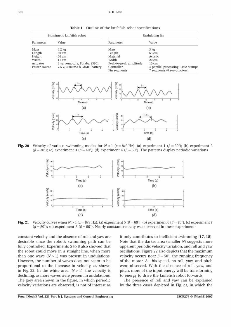
has reached either the inner or the outer limits of Figures 20 and 21 show the velocities measuredand generated for eight experiments with different b.the buoyancy tank.
JSCE276 © IMechE 2007Proc. IMechE Vol. 221 Part I: J. Systems and Control Engineering

305Mechatronics and buoyancy implementation of robotic fish
Fig. 18 Depth_Controller program flow chart
The four experimental results in Fig. 20 show apattern with periodic variations. Another noteworthyobservation of Fig. 20 is that the pattern repeats itselfat a frequency near that of the undulating frequency,which is 8
9Hz.
Roll and yaw oscillations (see Fig. 19(a) for thedefinitions) were not apparent by direct observationsin experiments 5 to 8 in Fig. 21. The velocity curvesobtained from these experiments reveal that rolland yaw were completely absent when the robotis moving forwards. Their absence seems to confirmthe analysis made by Sfakiotakis et al. [17] andLindsey [18] stating that at least one wave (or cycle)is present when a fish is swimming.
Note that an undulating fin is normally character-ized by the number N of waves (or cycles) presented,which is related to b (rad) by
N=bnf2p
(6)
where nf
is the number of fin segments connectedby n
f+1 servomotors (n
f=7 in this case).
Figure 21 also shows the relatively constant velocitycurves obtained from experiments 5 to 8. Experi-Fig. 19 Knifefish robot swimming, by an anal fin, and
submerged 30 cm underwater. (b) Top view of ments 7 and 8 show small oscillations, as the robotthe experimental set-up in a 240 cm×80 cm was gaining speed from rest. A relatively constantwater tank and a video camera velocity was observed after 1 s. In other words, a
JSCE276 © IMechE 2007 Proc. IMechE Vol. 221 Part I: J. Systems and Control Engineering
306 K H Low
Table 1 Outline of the knifefish robot specifications
Biomimetic knifefish robot Undulating fin
Parameter Value Parameter Value
Mass 6.2 kg Mass 3 kgLength 80 cm Length 63 cmHeight 56 cm Material AcrylicWidth 11 cm Width 20 cmActuator 8 servomotors, Futaba S3801 Peak-to-peak amplitude 10 cmPower source 7.5 V, 3000 mA h NiMH battery Controller 4 parallel processing Basic Stamps
Fin segments 7 segments (8 servomotors)
Fig. 20 Velocity of various swimming modes for N<1 (a=8/9 Hz): (a) experiment 1 (b=20°); (b) experiment 2(b=30°); (c) experiment 3 (b=40°); (d) experiment 4 (b=50°). The patterns display periodic variations
Fig. 21 Velocity curves when N>1 (a=8/9 Hz): (a) experiment 5 (b=60°); (b) experiment 6 (b=70°); (c) experiment 7(b=80°); (d) experiment 8 (b=90°). Nearly constant velocity was observed in these experiments
constant velocity and the absence of roll and yaw are it only contributes to inefficient swimming [17, 18].Note that the darker area (smaller N) suggests moredesirable since the robot’s swimming path can be
fully controlled. Experiments 5 to 8 also showed that apparent periodic velocity variation, and roll and yawoscillations. Figure 22 also depicts that the maximumthe robot could move in a straight line, when more
than one wave (N>1) was present in undulations. velocity occurs near b=50°, the running frequencyof the motor. At this speed, no roll, yaw, and pitchHowever, the number of waves does not seem to be
proportional to the increase in velocity, as shown were observed. With the absence of roll, yaw, andpitch, more of the input energy will be transformingin Fig. 22. In the white area (N>1), the velocity is
declining, as more waves were present in undulations. to energy to drive the knifefish robot forwards.The presence of roll and yaw can be explainedThe grey area shown in the figure, in which periodic
velocity variations are observed, is not of interest as by the three cases depicted in Fig. 23, in which the
JSCE276 © IMechE 2007Proc. IMechE Vol. 221 Part I: J. Systems and Control Engineering

307Mechatronics and buoyancy implementation of robotic fish
unbalanced force to the balanced force in case (c) ismuch smaller than that in case (b). This results inmuch less roll and yaw (almost none).
6 CONCLUSION AND FUTURE WORK
An integrated mechanism has been developed toenable the fin rays to oscillate in arbitrary waves ata certain phase lead or lag. The integrated systemconsists of a buoyancy fish body attached to which
Fig. 22 Velocity of the 63 cm fin obtained from the is a set of flexible fins. The designed modular finwater tank experiment (a=8/9 Hz). Owing to
mechanism can also be redesigned better to mimicthe oscillatory nature of velocity for b less thanthe swimming modes of fish with different fin types.60°, the velocity in the grey area is plotted onArbitrary or non-harmonic fin waves can be achievedthe basis of its time-averaged valueby varying the rotation and phase difference ofthe servomotors. Because the fin is made of a rigidmaterial and because of independent control of eachfin ray, the application of the modular fin mechanismis not limited to oscillating fins.
A more thorough study on fin locomotion andhydrodynamics should be carried out in order torender proper and efficient control action on thecurrent robot. An efficient force measurement of therobotic fish will be useful to the locomotion study.Therefore, future experiments should focus on howto obtain the force and the power of the undulatingfins. The results enable the effective undulations forenergy saving to be determined.Fig. 23 Undulating-fin forces in three cases
The future of biomimetic application relies onthe advanced development of actuators. Emergingbiologically inspired materials [24–28] such ascomponent of force perpendicular to the direction
of travel of the knifefish robot is shown. electro-active polymer and shape-memory polymersuggest avenues worth pursuing, which may replaceIn case (a), as the phase difference b is about 55°,
the number of waves formed along the undulating current motor-based actuators. These smart materialshave a potential in modelling the fish muscles,fin is N=1 (see Fig. 22). When this happens, the force
acted by the undulating fin on the surrounding water including undulating fins.Future focus will also be on data acquisition fromis shown in Fig. 23(a). The force acting on the water
towards the left equals the force acting on the water experiments, which can then be used to analysethe deployability (feasibility for deployment) of thetowards the right, i.e. F
L=F
R, the case of balancing.
In case (b), as the phase difference is less than 55°, robotic fish. Useful areas can also include the missionexecution by a school of robotic fish led by a masterthe number of waves formed along the undulating
fin is N<1. When this happens, the force acted or parent unit. The communication and coordinationamong the units are especially crucial in these appli-by the undulating fin on the surrounding water is
shown in Fig. 23(b). The force acting on the water cations. Research methodology and technology ofvehicle navigation is also crucial to the localizationtowards the left is larger than the force acting on the
water towards the right, i.e. FL>F
R. This causes an and recovery of robot fish in open water.
Longer battery life and more efficient com-unbalance of force and results in the presence of rolland yaw. munication systems are other issues before the robot
fish can be implemented and adopted for usefulIn case (c), as the phase difference is more than 55°,the number of waves formed along the undulating applications in the marine and defence industries. It
will also be worthwhile to explore the use of sensorsfin is N>1. Similar to case (b), there is an unbalanceforce with F
L>F
R. This again results in the presence that could imitate the lateral line sensory organs of
fish that they use to regulate their swimming inof roll and yaw. However, the percentage of resultant
JSCE276 © IMechE 2007 Proc. IMechE Vol. 221 Part I: J. Systems and Control Engineering

308 K H Low
9 Triantafyllou, M. S. and Triantafyllou, G. S. Anresponse to external ‘disturbances’. In conclusion,efficient swimming machine. Sci. Am., 1995, 272,the ultimate goal is to design fish-like submersible64–70.robots, which might be quieter, more manoeuvrable,
10 Wolfgang, M., Tolkoff, S., Techet, A., Barrett, D.,and possibly more energy efficient, when comparedTriantafyllou, M. S., Yue, D., Hover, F.,
with those submersibles using other means. Grosenbaugh, M., and McGillis, W. Drag reductionand turbulence control in swimming fish-like bodies.In Proceedings of the International Symposium onSeawater drag reduction, Newport, Rhode Island,USA July 1998, pp. 463–469.ACKNOWLEDGEMENTS
11 McHenry, M. J., Pell, C. A., and Long, Jr, J. H.Mechanical control of swimming speed: stiffnessThe author wishes to thank reviewers for theirand axial wave form in undulating fish models.
constructive suggestions that have greatly improved J. Expl Biology, 1995, 198, 2293–2305.the quality of the revised version. Thanks are also due 12 Rosenberger, L. J. and Westneat, M. W. Functionalto Dr F. M. J. Nickols for his valuable assistance in the morphology of undulatory pectoral fin locomotionearly stage of the development of the first prototype. in the stingray Taeniura Lymma (Chondrichthyes:Help given by Miss T. S. Indrawati, Mr A. Willy, and Dasyatidae). J. Expl Biology, 1999, 202, 3523–3539.
13 Lauder, G. V. and Drucker, E. G. Morphology andMr W. L. Aw on the prototype development areexperimental hydrodynamics of fish fin controlgreatly appreciated. The author would also like tosurfaces. IEEE J. Oceanic Engng, 2004, 29(3), 556–571.acknowledge the support from Dr Gerald Seet, the
14 Westneat, M. W., Thorsen, D. H., Walker, J. A., andDirector of Robotics Research Center (RRC), and theHale, M. E. Structure, function, and neural control
technicians of the RRC at the water tank, electronic of pectoral fins in fishes. IEEE J. Oceanic Engng,equipment, and other facilities. 2004, 29(3), 674–683.
15 Standen, E. M. and Lauder, G. V. Dorsal and analfin function in bluegill sunfish Lepomis macrochirus:three-dimensional kinematics during propulsionand maneuvering. J. Expl Biology, 2005, 208,2753–2763.
REFERENCES 16 Breder, C. M. The locomotion of fishes. Zoologica,1926, 4, 159–297.
1 Triantafyllou, M. S., Triantafyllou, G. S., and 17 Sfakiotakis, M., Lane, D. M., and Davies, J. B. C.Yue, D. K. P. Hydrodynamics of fishlike swimming. Review of fish swimming modes for aquatic loco-A. Rev. Fluid Mechanics, 2000, 32, 33–53. motion. IEEE J. Oceanic Engng, 1999, 24, 237–252.
2 How ships traffic noise affects whales in a shipping 18 Lindsey, C. C. Form, function and locomotorychannel http://www.pbs.org/odyssey/odyssey/ habits in fish. In Fish Physiology, VII, Locomotion20030506_log_transcript.html, May 2003. (Eds W. S. Hoar and D. J. Randall), 1978, pp. 1–100
3 Fish, F. E. Limits of nature and advances of tech-(Academic Press, New York).nology: what does biomimetics have to offer to
19 Kier, W. M. and Thompson, J. T. Muscle arrange-aquatic robots. Appl. Bionics and Biomechanics, 3(1),ment, function and specialization in recent coleoids.2006, 49–60.Berliner Palaobiologische Abhandlungen 03, 141–162.4 Hover, F. S. and Triantafyllou, M. S. Some robotic
20 Low, K. H. and Willy, A. Biomimetic motionapplications in fluid mechanics: vortex-inducedplanning of an undulating robotic fish fin. J. Vib.vibrations and fish propulsion. In Proceedings of theControl, 12(12), 1337–1359.Fluids Engineering Division, ASME Summer Meeting,
21 Willy, A. Design and development of undulating fin.Washington, DC, USA, 1998 (American Society ofMaster’s Thesis, School of Mechanical and AerospaceMechanical Engineers, New York).Engineering, Nanyang Technological University,5 Kato, N. Locomotion by mechanical pectoral fins.Singapore, 2005.J. Mar. Sci. Technol., 1998, 3, 113–121.
22 Willy, A. and Low, K. H. Initial experimental investi-6 Read, D. Fins for control and maneuvering of under-gation of undulating fin. In Proceedings of thewater vehicles. MS Thesis, Massachusetts InstituteIEEE–RSJ International Conference on Intelligentof Technology, Cambridge, Massachusetts, 1999.robots and systems (IROS2005), Edmonton, Canada,7 Barrett, D. S., Triantafyllou, M. S., Yue, D. K. P.,2005, pp. 1600–1605 (IEEE, New York).Grosenbaugh, M. A., and Wolfgang, M. Drag
23 Helfman, G. S., Collette, B. B., and Facey, D. E. Thereduction in fish-like locomotion. J. Fluid Mechanics,diversity of fishes, 1999 (Blackwell Science, Oxford).1999, 392, 183–212.
24 Kim, B., Kim, D.-H., Jung, J., and Park, J.-O. A8 Barrett, D. S. Propulsive efficiency of a flexiblebiomimetic undulatory tadpole robot using ionichull underwater vehicle. PhD Thesis, Massachusettspolymer–metal composite actuators. Smart Mater.Institute of Technology, Cambridge, Massachusetts,
1996. Structs, 2005, 14, 1579–1585.
JSCE276 © IMechE 2007Proc. IMechE Vol. 221 Part I: J. Systems and Control Engineering

309Mechatronics and buoyancy implementation of robotic fish
25 Paquette, J. W. and Kim, K. J. Ionomeric electro- 27 Guo, S., Fukuda, T., and Asaka, K. A new type ofactive polymer artificial muscle for naval applications. fish-like underwater microrobot. IEEE/ASME Trans.IEEE J. Oceanic Engng, 2004, 29, 729–737. Mechatronics, 2003, 8(1), 136–141.
26 Punning, A., Anton, M., Kruusmaa, M., and 28 Sfakiotakis, M., Lane, D. M., and Davies, B. C. AnAabloo, A. A biologically inspired ray-like underwater experimental undulating-fin device using the parallelrobot with electroactive polymer pectoral fins. In bellows actuator. In Proceedings of the IEEE Inter-Proceedings of the IEEE International Conference on national Conference on Robotics and automation,Mechatronics and robotics (MechRob2004), Aachen, Seoul, South Korea, 2001 (IEEE, New York).2004, Vol. 2, pp. 241–245 (IEEE, New York).
JSCE276 © IMechE 2007 Proc. IMechE Vol. 221 Part I: J. Systems and Control Engineering