
Mechanisms of structural organizational processes as revealed by real time mechano optical behavior...
10
Mechanisms of structural organizational processes as revealed by real time mechano optical behavior of PET film during sequential biaxial stretching Mohamed K. Hassan, Miko Cakmak * Polymer Engineering Department, University of Akron, 250 South Forge Street, Akron, OH 44325, United States article info Article history: Received 2 June 2014 Received in revised form 31 July 2014 Accepted 3 August 2014 Available online 19 August 2014 Keywords: Biaxial stretching Stress optical PET film abstract The main focus of this research is to identify the structural mechanisms that are responsible for changes observed in various stages of coupled mechano-optical (stress and strain optical) relationships as they are influenced by the deformation mode, level and rate. This involves in situ real time studies of the true- stress-strain-birefringence of sequential biaxially stretched PET films using a highly instrumented biaxial stretching machine and ex situ structural studies. These ex-situ studies include wide angle X-ray diffraction, Raman spectroscopy and DSC thermal analysis to examine the orientation, conformation and crystallization behaviors as well as formation of long range connectivity through physical network. The relationship between the stress and birefringence exhibited three Regimes. Regime I, linear relationship with a stress optical constant of 5.8 GPa 1 . Regime II, non-linear relationship with the establishment of chain tautness and nematic like two-dimensional order. Regime III, where the chains reach their finite extensibility. © 2014 Elsevier Ltd. All rights reserved. 1. Introduction The polyethylene terephthalate (PET) is a slow crystallizing polymer, which can be quenched from the melt into amorphous or to a semi-crystalline state depending on the cooling rate [1]. Stretching the film above the glass transition temperature generally causes what is called stress-induced crystallization as a result of orientation of polymer chains parallel to each other. The PET films are used in many applications including photo- graphic films, laminated metallic films, flexible disks for media storage, magnetic recording tapes, thermal transfer ribbons, printing sheets, packaging films as Oxygen barrier, insulation films, and heat shrinkage flexible films. Each of these applications de- mands special properties to be imparted on these films and these are accomplished through the control of thermal deformation history; including temperature, rate, ratio and mode of deformation. Biaxial hot drawing of amorphous PET is an integral feature of some important industrial processes, such as thermoforming, bottle stretch-blow molding and biaxial film drawing [2]. Sequen- tial biaxial stretching is practiced in a number of polymer pro- cessing operations including tenter frame biaxial stretching and stretch blow molding. The advantage of the sequential stretching [3] as compared to simultaneous stretching depends very much on the type of material being processed [4]. If the precursor material does not contain large super structural features such as crystallites, as typically observed in polymers of slow crystallization character like PET, PEN, PPS and PEEK; then it is advantageous to use the sequential process. This is because, the uniaxial stretching impar- ted in the first stage accelerates the stress induced crystallization thereby leading to self-leveling deformation and uniform thickness products at smaller areal expansion ratios (l MD l TD ). If on the other hand the precursor films are structured such as in the case of PP and Nylon6, the reports in the literature suggest that simulta- neous biaxial stretching is advantageous [5]. In such systems, in plane balanced properties are easier to achieve in simultaneous mode [6] that is also reported to provide higher mechanical properties. Chandran and Jabarin [7,8] found during biaxial sequential extension of PET that, the stressestrain curve is concave upward at low strain rates and becomes convex upward at higher strain rates due to strain hardening. The curve also changes from concave to convex upward at high limiting extension ratios in MD direction. * Corresponding author. Polymer Engineering Academic Center, The University of Akron, 250 South Forge Street, Akron, OH 44325-0301, United States. Tel.: þ1 330 972 6413. E-mail address: [email protected] (M. Cakmak). Contents lists available at ScienceDirect Polymer journal homepage: www.elsevier.com/locate/polymer http://dx.doi.org/10.1016/j.polymer.2014.08.005 0032-3861/© 2014 Elsevier Ltd. All rights reserved. Polymer 55 (2014) 5245e5254
Transcript of Mechanisms of structural organizational processes as revealed by real time mechano optical behavior...
lable at ScienceDirect
Polymer 55 (2014) 5245e5254
Contents lists avai
Polymer
journal homepage: www.elsevier .com/locate/polymer
Mechanisms of structural organizational processes as revealed by realtime mechano optical behavior of PET film during sequential biaxialstretching
Mohamed K. Hassan, Miko Cakmak*
Polymer Engineering Department, University of Akron, 250 South Forge Street, Akron, OH 44325, United States
a r t i c l e i n f o
Article history:Received 2 June 2014Received in revised form31 July 2014Accepted 3 August 2014Available online 19 August 2014
Keywords:Biaxial stretchingStress opticalPET film
* Corresponding author. Polymer Engineering AcadeAkron, 250 South Forge Street, Akron, OH 44325-030972 6413.
E-mail address: [email protected] (M. Cakmak
http://dx.doi.org/10.1016/j.polymer.2014.08.0050032-3861/© 2014 Elsevier Ltd. All rights reserved.
a b s t r a c t
The main focus of this research is to identify the structural mechanisms that are responsible for changesobserved in various stages of coupled mechano-optical (stress and strain optical) relationships as theyare influenced by the deformation mode, level and rate. This involves in situ real time studies of the true-stress-strain-birefringence of sequential biaxially stretched PET films using a highly instrumented biaxialstretching machine and ex situ structural studies. These ex-situ studies include wide angle X-raydiffraction, Raman spectroscopy and DSC thermal analysis to examine the orientation, conformation andcrystallization behaviors as well as formation of long range connectivity through physical network. Therelationship between the stress and birefringence exhibited three Regimes. Regime I, linear relationshipwith a stress optical constant of 5.8 GPa�1. Regime II, non-linear relationship with the establishment ofchain tautness and nematic like two-dimensional order. Regime III, where the chains reach their finiteextensibility.
© 2014 Elsevier Ltd. All rights reserved.
1. Introduction
The polyethylene terephthalate (PET) is a slow crystallizingpolymer, which can be quenched from the melt into amorphous orto a semi-crystalline state depending on the cooling rate [1].Stretching the film above the glass transition temperature generallycauses what is called stress-induced crystallization as a result oforientation of polymer chains parallel to each other.
The PET films are used in many applications including photo-graphic films, laminated metallic films, flexible disks for mediastorage, magnetic recording tapes, thermal transfer ribbons,printing sheets, packaging films as Oxygen barrier, insulation films,and heat shrinkage flexible films. Each of these applications de-mands special properties to be imparted on these films and theseare accomplished through the control of thermal deformationhistory; including temperature, rate, ratio and mode ofdeformation.
Biaxial hot drawing of amorphous PET is an integral feature ofsome important industrial processes, such as thermoforming,
mic Center, The University of1, United States. Tel.: þ1 330
).
bottle stretch-blow molding and biaxial film drawing [2]. Sequen-tial biaxial stretching is practiced in a number of polymer pro-cessing operations including tenter frame biaxial stretching andstretch blow molding. The advantage of the sequential stretching[3] as compared to simultaneous stretching depends very much onthe type of material being processed [4]. If the precursor materialdoes not contain large super structural features such as crystallites,as typically observed in polymers of slow crystallization characterlike PET, PEN, PPS and PEEK; then it is advantageous to use thesequential process. This is because, the uniaxial stretching impar-ted in the first stage accelerates the stress induced crystallizationthereby leading to self-leveling deformation and uniform thicknessproducts at smaller areal expansion ratios (lMD � lTD). If on theother hand the precursor films are structured such as in the case ofPP and Nylon6, the reports in the literature suggest that simulta-neous biaxial stretching is advantageous [5]. In such systems, inplane balanced properties are easier to achieve in simultaneousmode [6] that is also reported to provide higher mechanicalproperties.
Chandran and Jabarin [7,8] found during biaxial sequentialextension of PET that, the stressestrain curve is concave upward atlow strain rates and becomes convex upward at higher strain ratesdue to strain hardening. The curve also changes from concave toconvex upward at high limiting extension ratios in MD direction.
M.K. Hassan, M. Cakmak / Polymer 55 (2014) 5245e52545246
The convex upward nature of the stressestrain curve is typical ofsemi-crystalline materials, indicating the occurrence of strain-induced crystallization during stretching in MD direction. Lorentzand co-workers [9,10] studied the amorphous orientation ofsequentially biaxially stretched PET films and concluded that, thephenyl ring plane normals in the amorphous phase tend to becomemore perpendicular to the draw direction. They did not find amarked tendency for the rings to lie in the plane of the film on thecontrary with the crystalline phase. They also observed that, TDstretching causes break down of some of the crystals formed duringthe MD stretching.
Daubeny et al. [11] showed that PET crystallizes in triclinic form.The intrinsic optical properties of PET in three crystallographic axesto be [27]: na ¼ 1.372, nb ¼ 1.781 and nc ¼ 1.793 and averagerefractive indices for the crystalline and amorphous phases asNc ¼ 1.6486 and Nam ¼ 1.575 respectively. The intrinsic bi-refringences for the amorphous and crystalline phases are;D
�am ¼ 0.275 and D
�c ¼ 0.2165 respectively. Yoshihara et al. [26].
found that the lowest refractive index for the crystalline PET is inthe direction normal to the phenyl planes.
Extensive studies [12e44] focused on the structural de-velopments during the biaxial stretching processes of PET. Gohil[32] found that, in sequential stretching, a balanced biaxial orien-tation distribution is achieved at a TD draw ratio significantly belowthe MD draw ratio. At equal MD and TD draw ratios, one obtainsunbalanced biaxial orientation in the films. This is in contrast to theequal biaxially stretched films in simultaneous biaxial mode thatexhibit balanced orientation. In sequentially balanced biaxiallystretched films, the crystalline chains are found to be predomi-nantly oriented along the TD direction.
Stress-optical behavior of PET films under stretching conditionsin the rubbery region was studied by many authors. A value of3.8e8 GPa�1 for the stress optical constant was reported by Ajji[45,46] who stated that, the deviation from SOR was due to stress-induced crystallization, which also causes a faster increase inbirefringence than the stress. Also a value of 3.8 GPa�1 was reportedby Ryu [47]. Gorlier [1] connected the occurrence of the crystalli-zation of PET with a minimum strain value that needs to bereached. According to Inoue [48] the linear relationship betweenthe stress and birefringence above the glass transition temperatureis due to the deviatoric component of refractive index tensor, whichis proportional to that of the stress tensor.
Many authors tried to explain the deviation from the SOR in thelow strain region either by the crystallization of the system asstated by Ajji and Ryu, or as in case of Kroger et al. [49]. who relatedthe deviation from the rule to an additional stress contribution [50]or stress offset in the stress optical diagram, which depends on thestretching rate. While, at high strain levels Ryu attributed the de-viation from the SOR to the finite extensibility of the chains.
In none of the above studies, the true real time strainestress andbirefringence behavior was investigated in sequential biaxialstretching. In a coupled manner, we studied the linear and non-linear stress optical behavior and other mechano-optical relation-ships as the PET films are undergoing sequential biaxial stretchingin real time. Monitoring all of these parameters together in realtime is essential to delineate the relationship between the defor-mation behavior and structure that is the subject of current work.
2. Experimental section
2.1. Material
Polyethylene terephthalate (PET) commercial film provided byM and G polymers was used in this study. The film has an intrinsic
viscosity of 0.80 dl/mg and 28,470 number average molecularweight [51].
2.2. Stretching system and parameters
The biaxial stretching system was highly instrumented in ourlaboratory [52] to apply a wide range of processing modes as:Uniaxial Constant Width (UCW), Simultaneous Biaxial (SB) andSequential Biaxial (SEQB). In addition, stretching rates and rateprofiles were applied to the films at constant set of processingparameters. The unique instrumentation features of the systemallow the real time monitoring of the true stresses, true strains, inplane and out of plane birefringences. The samples measured14 cm� 14 cm as cut from the cast film. A special dotmatrix patternwas painted on the films using Fluorescent paint and IR light tomonitor the strains of the films while stretching by following thedots movement with a high speed CCD camera. After setting thestretching temperature to 95 �C, a temperature equilibration timefor the chamber of at least 1 h was used, and then the film wasinserted in the chamber and held by pneumatically activatedclamps. After an additional equilibration time of 6e8 min for thesample inside the thermal chamber, stretching was started. Thefilms were stretched at three different rates of 0.00125 s�1
(0.15 mm/s), 0.0125 s�1 (1.5 mm/s) and 0.125 s�1 (15 mm/s). Afterstretching to the desired stretching ratios, the films were imme-diately cooled down below the glass transition temperature with afan while the sample is held in the clamps. The sequential biaxialstretching takes place in two stages: Stretching in machine (MD orY) direction, whichwewill call MD-stretch. This stage takes place ata constant width, where the transverse (TD or X) direction motor isnot activated. Stretching in the transverse (TD or X) direction,which we will call TD-stretch. This stage occurs at constant length,where machine direction motor is not activated. Films with thefollowing stretch ratios (lMD� lTD) were obtained: 1.5�1, 1.5�1.5,1.75 � 1.75, 2 � 1, 2 � 1.5, 2 � 2, 2.5 � 1, 2.5 � 1.5, 2.5 � 2, 3 � 1 and3 � 1.25. This range was limited by the strength of the film againstthe clamping forces.
3. Experimental procedure for off line measurements
3.1. Laser Raman spectroscopy
The Raman spectra of the samples were obtained by HoloProbeVPT laser Raman system made by Kaiser Optical Systems. Flatunscratched samples were used to obtain the spectra from 40 scansand each scan lasted for 40 s. This means 1600 s for acquiring thedark intensity and 1600 s for acquiring the sample spectra to give atotal scanning time of 3200 s to minimize the noise to signal ratio.The range of Raman shift obtained for each spectrawas from�40 to3450 cm�1. PET exhibits an almost planar and extended structure[53] and it has two principal constituents; a substituted benzenering and an ethylene glycol group. PET has two chain conformationsgauche and trans with the former has a higher conformational en-ergy. The stretching process works on decreasing the energy of thesystem, which leads to the crystallization and transformation fromthe high energy gauche to the lower energy trans conformation.Pastor [54] and coworkers have taken the band at 793 cm�1 as areference band as it does not show large spectral changes. The bandwas used as a reference to quantify the spectral changes resultedfrom the stretching process [55]. Stroker [56] assigned the peak at886 cm�1 to the gauche conformation in the ethylene glycol seg-ments, and the 998 cm�1 corresponds to the OeCH2 stretching,trans conformation of the ethylene glycol segments.
The crystallinity change was calculated from the gauche-transconformation change by calculating the intensity ratio of the
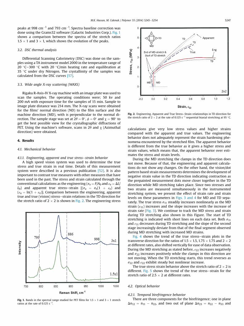
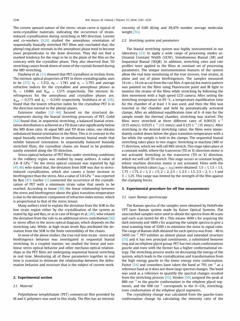
Fig. 2. Engineering, Apparent and True StresseStrain relationships in TD direction forthe stretch ratio of 2 � 2 at the rate of 0.125 s�1 sequential biaxial stretching at 95 �C.
M.K. Hassan, M. Cakmak / Polymer 55 (2014) 5245e5254 5247
peaks at 998 cm�1 and 793 cm�1. Spectra baseline correction wasdone using the Grams32 software (Galactic Industries Corp.). Fig. 1shows a comparison between the spectra of the stretch ratios1.5 � 1 and 3 � 1, which shows the evolution of the peaks.
3.2. DSC thermal analysis
Differential Scanning Calorimetry (DSC) was done on the sam-ples using a TA instrument model 2000 in the temperature range of20 �Ce300 �C with 20 �C/min heating rate and equilibration at35 �C under dry Nitrogen. The crystallinity of the samples wascalculated from the DSC curves [57].
3.3. Wide angle X-ray scattering (WAXS)
Rigaku R-Axis-IV X-raymachinewith an image platewas used toscan the samples. The operating conditions were; 50 kv and200 mA with exposure time for the samples of 15 min. Sample toimage plate distance was 214 mm. The X-ray scans were obtainedfor the films' normal direction (ND) to the film surface and themachine direction (MD), with is perpendicular to the normal di-rection. The sample stage was set at 2q ¼ 0�, f ¼ 0� and c ¼ 90� toget the best possible view for the crystallographic diffractions ofPET. Using the machine's software, scans in 2q and c (Azimuthaldirection) were obtained.
4. Results
4.1. Mechanical behavior
4.1.1. Engineering, apparent and true stressestrain behaviorA high speed vision system was used to determine the true
stress and true strain in real time. Details of this measurementsystem were described in a previous publication [52]. It is alsoimportant to contrast true measures with other measures that havebeen used in the past. The stress and strain calculated through theconventional calculations as the engineering (se ¼ F/A0 and εe¼ DL/L0) and apparent true stressestrain [(sa ¼ se(1 þ εe) and(εa ¼ ln(1 þ εe)]. Comparison between the engineering, apparenttrue and true (vision) stressestrain relations in the TD direction forthe stretch ratio of 2 � 2 is shown in Fig. 2. The engineering stress
Fig. 1. Bands in the spectral range studied for PET films for 1.5 � 1 and 3 � 1 stretchratios at the rate of 0.125 s�1.
calculations give very low stress values and higher strainscompared with the apparent and true values. The engineeringbehavior does not adequately represent the strain hardening phe-nomena encountered by the stretched film. The apparent behavioris different from the true behavior as it gives a higher stress andstrain values, which means that, the apparent behavior over esti-mates the stress and strain levels.
During the MD stretching the clamps in the TD direction doesnot move. Because of that, the engineering and apparent calcula-tions do not show any changes. On the other hand, the vision/dotpattern based strainmeasurements determines the development ofnegative strain value in the TD direction indicating contraction asthe prepainted measurement dots move closer together in the TDdirection while MD stretching takes place. Since two stresses andtwo strains are measured simultaneously in the instrumentedstretching system, we present the effect of strain rate and strainlevels on these parameters in Figs. 3 and 4 for MD and TD sepa-rately. The true stress s11 steadily increases nonlinearly as the MDstrain (ε11) increases and the slope increases with the increase ofstrain rate (Fig. 3). We continue to track the MD stress and strainduring TD stretching also shown in this Figure. The start of TDstretching is indicated with short lines on each data set. Both s11and ε11 decreases during TD stretching and the slope of the secondstage increasingly deviate from that of the final segment observedduring MD stretching with increased MD strains.
Fig. 4 shows the trend of the true stressestrain plots in thetransverse direction for the ratios of 1.5 � 1.5, 1.75 � 1.75 and 2 � 2at different rates, also shifted vertically for ease of data observation.During the MD stretching as stated before, ε22 increases negativelyand s22 increases positively while the clamps in this direction arenot moving. When the TD stretching starts, this trend reverses ass22 and ε22 exhibit steady but nonlinear increase.
The true stress strain behavior above the stretch ratio of 2 � 2 isdifferent. Fig. 5 shows the trend of the true stressestrain for thestretch ratio of 2.5 � 2 at different rates.
4.2. Optical behavior
4.2.1. Temporal birefringence behaviorThere are three components for the birefringence; one in plane
Dn12 ¼ n11 � n22, and two out of plane Dn23 ¼ n22 � n33 and
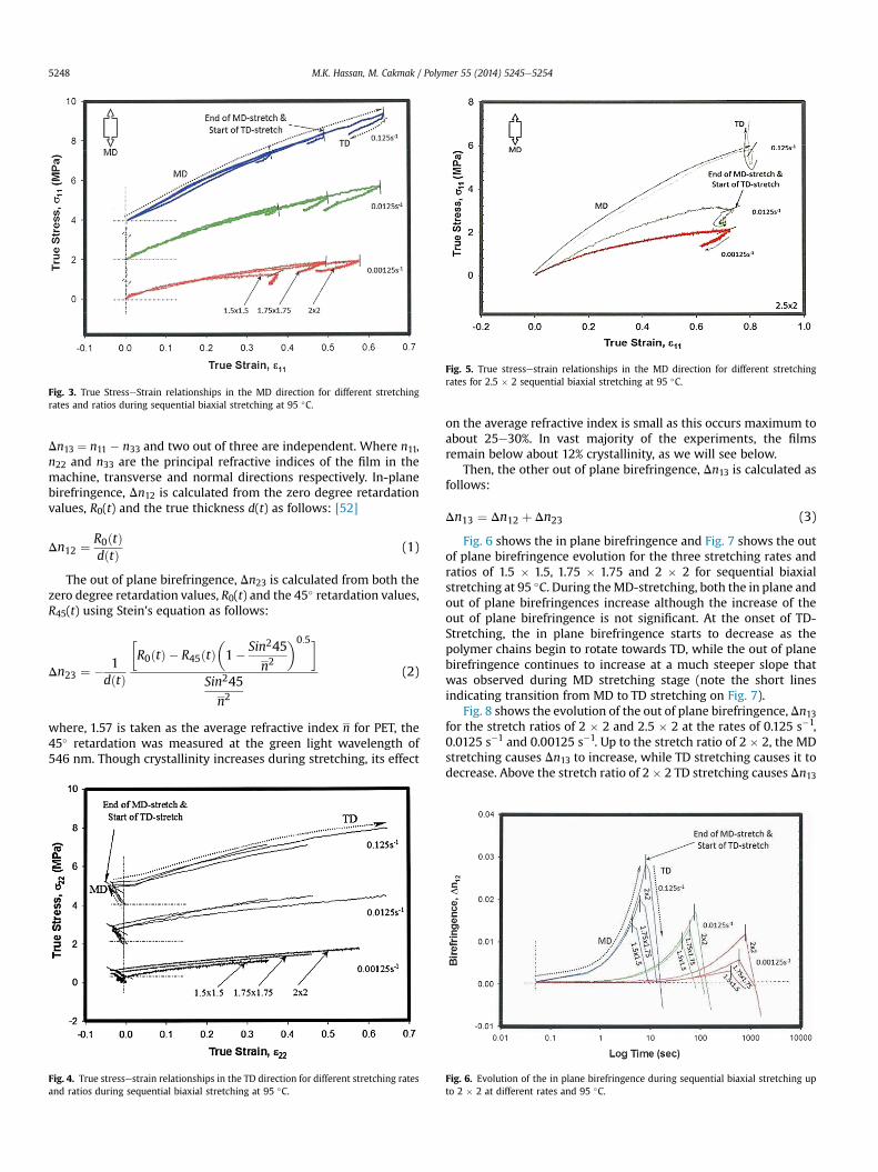
Fig. 3. True StresseStrain relationships in the MD direction for different stretchingrates and ratios during sequential biaxial stretching at 95 �C.
Fig. 5. True stressestrain relationships in the MD direction for different stretchingrates for 2.5 � 2 sequential biaxial stretching at 95 �C.
M.K. Hassan, M. Cakmak / Polymer 55 (2014) 5245e52545248
Dn13 ¼ n11 � n33 and two out of three are independent. Where n11,n22 and n33 are the principal refractive indices of the film in themachine, transverse and normal directions respectively. In-planebirefringence, Dn12 is calculated from the zero degree retardationvalues, R0(t) and the true thickness d(t) as follows: [52]
Dn12 ¼ R0ðtÞdðtÞ (1)
The out of plane birefringence, Dn23 is calculated from both thezero degree retardation values, R0(t) and the 45� retardation values,R45(t) using Stein's equation as follows:
Dn23 ¼ � 1dðtÞ
�R0ðtÞ � R45ðtÞ
�1� Sin245
n2
�0:5�
Sin245
n2
(2)
where, 1.57 is taken as the average refractive index n for PET, the45� retardation was measured at the green light wavelength of546 nm. Though crystallinity increases during stretching, its effect
Fig. 4. True stressestrain relationships in the TD direction for different stretching ratesand ratios during sequential biaxial stretching at 95 �C.
on the average refractive index is small as this occurs maximum toabout 25e30%. In vast majority of the experiments, the filmsremain below about 12% crystallinity, as we will see below.
Then, the other out of plane birefringence, Dn13 is calculated asfollows:
Dn13 ¼ Dn12 þ Dn23 (3)
Fig. 6 shows the in plane birefringence and Fig. 7 shows the outof plane birefringence evolution for the three stretching rates andratios of 1.5 � 1.5, 1.75 � 1.75 and 2 � 2 for sequential biaxialstretching at 95 �C. During theMD-stretching, both the in plane andout of plane birefringences increase although the increase of theout of plane birefringence is not significant. At the onset of TD-Stretching, the in plane birefringence starts to decrease as thepolymer chains begin to rotate towards TD, while the out of planebirefringence continues to increase at a much steeper slope thatwas observed during MD stretching stage (note the short linesindicating transition from MD to TD stretching on Fig. 7).
Fig. 8 shows the evolution of the out of plane birefringence, Dn13for the stretch ratios of 2 � 2 and 2.5 � 2 at the rates of 0.125 s�1,0.0125 s�1 and 0.00125 s�1. Up to the stretch ratio of 2 � 2, the MDstretching causes Dn13 to increase, while TD stretching causes it todecrease. Above the stretch ratio of 2 � 2 TD stretching causes Dn13
Fig. 6. Evolution of the in plane birefringence during sequential biaxial stretching upto 2 � 2 at different rates and 95 �C.
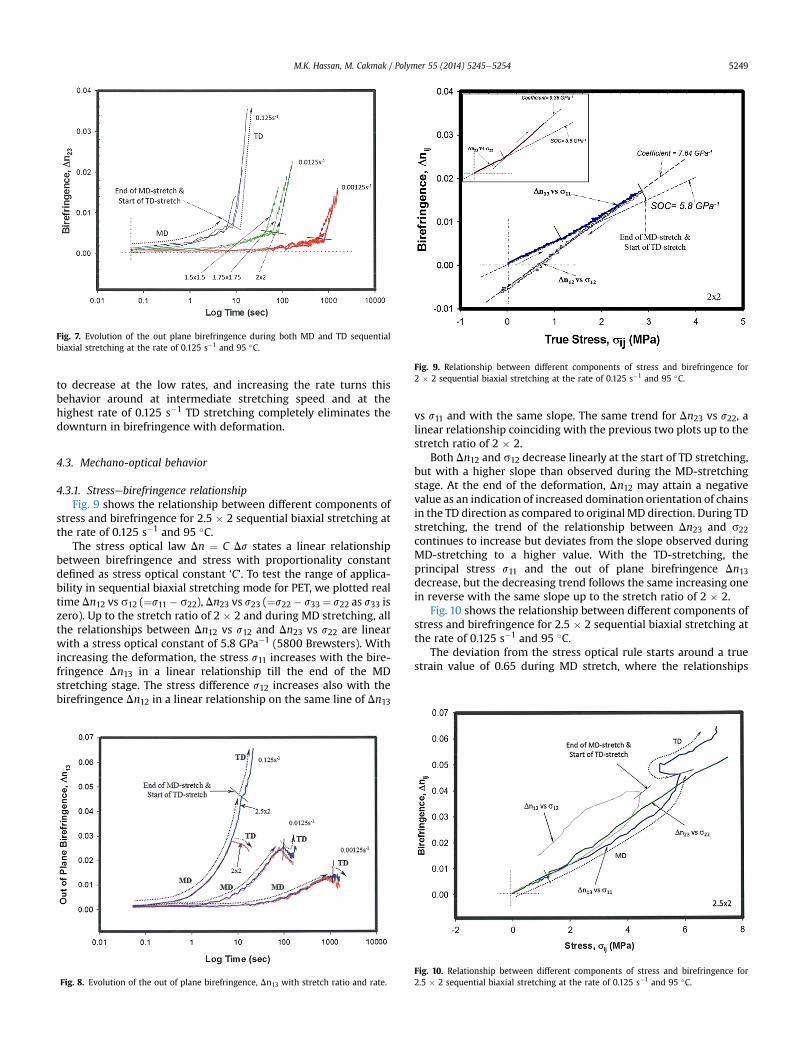
Fig. 7. Evolution of the out plane birefringence during both MD and TD sequentialbiaxial stretching at the rate of 0.125 s�1 and 95 �C.
Fig. 9. Relationship between different components of stress and birefringence for2 � 2 sequential biaxial stretching at the rate of 0.125 s�1 and 95 �C.
M.K. Hassan, M. Cakmak / Polymer 55 (2014) 5245e5254 5249
to decrease at the low rates, and increasing the rate turns thisbehavior around at intermediate stretching speed and at thehighest rate of 0.125 s�1 TD stretching completely eliminates thedownturn in birefringence with deformation.
4.3. Mechano-optical behavior
4.3.1. Stressebirefringence relationshipFig. 9 shows the relationship between different components of
stress and birefringence for 2.5 � 2 sequential biaxial stretching atthe rate of 0.125 s�1 and 95 �C.
The stress optical law Dn ¼ C Ds states a linear relationshipbetween birefringence and stress with proportionality constantdefined as stress optical constant ‘C’. To test the range of applica-bility in sequential biaxial stretching mode for PET, we plotted realtime Dn12 vs s12 (¼s11 � s22), Dn23 vs s23 (¼s22 � s33 ¼ s22 as s33 iszero). Up to the stretch ratio of 2 � 2 and during MD stretching, allthe relationships between Dn12 vs s12 and Dn23 vs s22 are linearwith a stress optical constant of 5.8 GPa�1 (5800 Brewsters). Withincreasing the deformation, the stress s11 increases with the bire-fringence Dn13 in a linear relationship till the end of the MDstretching stage. The stress difference s12 increases also with thebirefringence Dn12 in a linear relationship on the same line of Dn13
Fig. 8. Evolution of the out of plane birefringence, Dn13 with stretch ratio and rate.
vs s11 and with the same slope. The same trend for Dn23 vs s22, alinear relationship coinciding with the previous two plots up to thestretch ratio of 2 � 2.
Both Dn12 and s12 decrease linearly at the start of TD stretching,but with a higher slope than observed during the MD-stretchingstage. At the end of the deformation, Dn12 may attain a negativevalue as an indication of increased domination orientation of chainsin the TD direction as compared to original MD direction. During TDstretching, the trend of the relationship between Dn23 and s22continues to increase but deviates from the slope observed duringMD-stretching to a higher value. With the TD-stretching, theprincipal stress s11 and the out of plane birefringence Dn13decrease, but the decreasing trend follows the same increasing onein reverse with the same slope up to the stretch ratio of 2 � 2.
Fig. 10 shows the relationship between different components ofstress and birefringence for 2.5 � 2 sequential biaxial stretching atthe rate of 0.125 s�1 and 95 �C.
The deviation from the stress optical rule starts around a truestrain value of 0.65 during MD stretch, where the relationships
Fig. 10. Relationship between different components of stress and birefringence for2.5 � 2 sequential biaxial stretching at the rate of 0.125 s�1 and 95 �C.
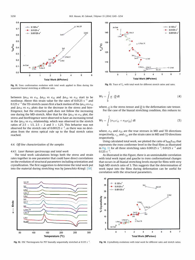
Fig. 11. Trans conformation evolution with total work applied to films during thesequential biaxial stretching at different rates.
Fig. 13. Trace of Tcc with total work for different stretch ratios and rates.
M.K. Hassan, M. Cakmak / Polymer 55 (2014) 5245e52545250
between Dn13 vs s11, Dn23 vs s22 and Dn12 vs s12 start to benonlinear. Above this strain value for the rates of 0.0125 s�1 and0.125 s�1 the TD-stretch causes first a backmotion of theDn12 vs s12and Dn13 vs s11 plots due to the decrease in the stress and bire-fringence, but the retraction path does not follow the increasingone during the MD-stretch. After that for the Dn13 vs s11 plot, thestress and birefringence were observed to have an increasing trendin the Dn13 vs s11 relationship, which was observed in the stretchratios of 2.5 � 1.5, 2.5 � 2 and 3 � 1.25. This behavior was notobserved for the stretch rate of 0.00125 s�1, as there was no devi-ation from the stress optical rule up to the final stretch ratiosreached.
4.4. Off-line characterization of the samples
4.4.1. Laser Raman spectroscopy and total workThe total work calculations brings both the stress and strain
rates together in one parameter that could have direct correlationson the evolution of structural parameters including orientation andcrystallization. The first suggestion to determine the total work putinto the material during stretching was by Janeschitz-Kriegl: [58]
Fig. 12. DSC Thermograms for PET biaxially sequentially stretched at 0.125 s�1.
WT ¼Zt
0
s : D dt (4)
where, s is the stress tensor and D is the deformation rate tensor.For the case of the biaxial stretching condition, this reduces to:
WT ¼Zt
0
�s11ε
$11 þ s22ε
$22�dt (5)
where, s11 and s22 are the true stresses in MD and TD directionsrespectively, ε$11 and ε
$22 are the strain rates inMD and TD directions
respectively.Using calculated total work, we plotted the ratio of I998/I793 that
represents the trans conformer level in the final films as illustratedin Fig. 11 for all three stretching rates 0.00125 s�1, 0.0125 s�1 and0.125 s�1.
As illustrated in this Figure, there is an unmistakable correlationwith total work input and gauche to trans conformational changesthat occurs in all biaxial stretching levels except for films with veryhigh MD stretch ratio of 3. This suggests that the determination ofwork input into the films during deformation can be useful forcorrelation with the structural parameters.
Fig. 14. Crystallinity evolutions with total work for different rates and stretch ratios.
M.K. Hassan, M. Cakmak / Polymer 55 (2014) 5245e5254 5251
4.4.2. DSC thermal analysisFig. 12 shows the DSC thermograms for the sequentially biaxi-
ally stretched samples at the rate of 0.125 s�1.The cold crystallization peak temperature, Tcc, generally de-
creases with MD stretch with corresponding decrease in area. TDstretching either broadens these peaks and/or increases the peaktemperature to higher values. We observe similar behavior duringmelting, as the melting peak becomes broader with the increase ofbiaxiality (e.g. 1.75 � 1.75, 2.5 � 2) and narrower and shifts tohigher temperature when uniaxiality (e.g. 2 � 1, 3 � 1) is present.
The peak of cold crystallization temperature, Tcc was found tocorrelate quitewell with the total work input as illustrated in Fig.13where the Tcc decreases with total work input into the films. This isnot surprising as the effective work put into the material duringstretching generally goes to orientation of the amorphous chainsand this is directly observable by the decrease of Tcc and area underthis peak as an increasing fraction of polymer chains crystallize.
As a result, a similar correlation is noted for % crystallinity ob-tained in all these film for all rates of stretching as shown in Fig. 14particularly at low overall deformation levels.
At higher deformation, this correlation does not hold well. Thismight be because of the substantial amount of highly organizedstructure formations already took place in the first stretching di-rection (MD). While stretching in the TD direction tends to destroypart of the formed crystals by pulling the polymer chains fromthese crystalline regions at right angles. Later when sufficientnumbers of the chains regroup in the TD direction, then they startto recrystallize again.
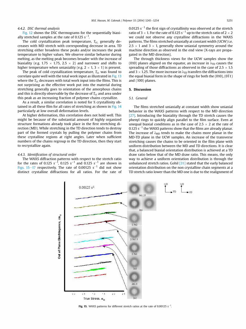
4.4.3. Identification of structural orderThe WAXS diffraction patterns with respect to the stretch ratio
for the rates of 0.125 s�1, 0.125 s�1 and 0.125 s�1 are shown inFigs. 15e17 respectively. The rate of 0.00125 s�1 did not showdistinct crystalline diffractions for all ratios. For the rate of
Fig. 15. WAXS patterns for different stre
0.0125 s�1 the first sign of crystallinity was observed at the stretchratio of 3� 1. For the rate of 0.125 s�1 up to the stretch ratio of 2� 2we could not observe any crystalline diffractions in the WAXSpatterns. The films stretched uniaxially at constant width (UCW) i.e.2.5 � 1 and 3 � 1, generally show uniaxial symmetry around themachine direction as observed in the end view (X-rays are propa-gated in the MD direction).
The through thickness views for the UCW samples show the(010) planes aligned on the equator, an increase in lTD causes thespreading of those diffractions as observed in the case of 2.5 � 1.5and 3� 1.25. Themore increase in lTD transfers the diffractions intothe equal biaxial form in the shape of rings for both the (010), (011)and (100) planes.
5. Discussion
5.1. General
The films stretched uniaxially at constant width show uniaxialbehavior in the WAXS patterns with respect to the MD direction[27]. Introducing the biaxiality through the TD stretch causes thephenyl rings to quickly align parallel to the film surface. Even atunequal biaxial conditions as in the case of 2.5 � 2 at the rate of0.125 s�1 theWAXS patterns show that the films are already planar.The increase of lMD tends to make the chains more planar in theMD-TD plane in the UCW samples. An increase of the transversestretching causes the chains to be oriented in the film plane withuniform distribution between the MD and TD directions. It is clearthat, a balanced biaxial orientation distribution is achieved at a TDdraw ratio below that of the MD draw ratio. This means, the onlyway to achieve a uniform orientation distribution is through theunbalanced stretch ratios. Gohil [31] stated that the early balancedorientation distribution on the non crystalline chain segments at aTD stretch ratio lower than the MD one is due to the realignment of
tch ratios at the rate of 0.00125 s�1.
Fig. 16. WAXS patterns for different stretch ratios at the rate of 0.0125 s�1.
Fig. 17. WAXS patterns for different stretch ratios at the rate of 0.125 s�1.
M.K. Hassan, M. Cakmak / Polymer 55 (2014) 5245e52545252
the MD oriented chains in the TD direction during the MDstretching. However, our system measurements indicated that,during the MD stretch, there is already indirect stress in the TDdirection working on orienting the chains in the TD direction.Consequently, the degree of stretching required to obtain thebalanced orientation in TD direction should be less than the MDstretching as the chains already have some degree of orientation inTD direction. In addition, we should note that, as the direction ofthe crystal growth is perpendicular to the stretching direction, theformed crystals during the MD stretching will be oriented in the TDdirection; therefore, the balanced crystalline reorientation shouldbe faster than the balanced amorphous orientation in the TDdirection.
5.2. Three-regime behavior
The behavior of the PET films during the sequential biaxialstretching can be observed as a three-Regime behavior as shown inFig. 18.
5.3. Regime I
We will call a low stress region (below a true strain of 0.65) inwhich the stress increases slowly with the draw ratio, Regime I.During the MD-stretch, the chains are oriented in the machinedirection causing an increase in the refractive index in the MD di-rection. The result is increasing Dn12 with the stretch ratio. Eventhough the main orientation direction during the MD-stretch is themachine direction, there is still an indirect stress in TD direction.This indirect stress causes the chains in the TD direction to startaligning themselves in that direction. Stretching up to a true strainof 0.65 and during theMD-stretch, the relationships between s11 vs
Dn13, s22 vs Dn23, and s12 vs Dn12 are all linear and laying on thesame line. This stage is a uniaxial constant width stretching; atwhich the stress-optical-rule is holding with a stress-optical-constant of 5.8 GPa�1 (5800 Brewsters) as was found in thesimultaneous biaxial stretching [59].
The relationship between the stress level and the trans contentshowed a steady increase of the trans content with the stress as asign of increasing the crystallinity and order in the stretched films.Up to a true strain of 0.65 for all stretching rates, the Ramanmeasurements showed the lowest degree of the trans isomercontent, as a sign of a lowest degree of crystallinity and order in thefilms compared with the higher stretch ratios. This is a result of theabsence of the strain induced crystallization and the high mobilityof the chains as they are not highly extended, which results in ahigh degree of internal energy. This also was observed for the rateof 0.00125 s�1 at all stretch ratios. When the chains are amorphousthey can freely move and the molecules have high energy enablingthem to have a high vibrational motion around their oscillationcenters. At the low stretch ratios, the transverse orientation occursentirely on the expense of the randomly oriented component,which leads to higher degree of order for the system even duringthe TD stretch [31] causing increase in the trans content. At low lMDup to a true strain of 0.65 an increase in lTD increases thecrystallinity.
5.4. Regime II
Regime II takes place above a true strain of 0.65 stretching of thefilm in MD direction. Starting the TD stretch and above this truestrain the crystallization and the network formation of the systemoccurred. Once crystalline regions are established, segmentalrelaxation slows down since the crystallites act as physical cross-linking nodes acting similar to entanglements [60]. There is anarrest in viscous flow correlates with the network formation. Theoccurrence of strain-induced crystallization works on locking-inthe highly oriented structure and leads to the extensive perma-nent deformation upon loading in the other direction. After that,
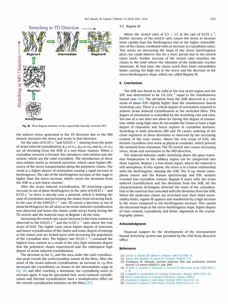
Fig. 18. Three-Regime behavior of the sequentially biaxially stretched PET.
M.K. Hassan, M. Cakmak / Polymer 55 (2014) 5245e5254 5253
the indirect stress generated in the TD direction due to the MDstretch, increases the stress and strain in that direction.
For the rates of 0.125 s�1and 0.0125 s�1, starting from the pointof strain induced crystallization D12 vs s12, D23 vs s22 and D13 vs s13are all deviating from the SOR in a non-linear manner. When acrystalline network is formed, this introduces new entities into thesystem, which are the solid crystallites. The introduction of thesenew entities works as network junctions, which cause higher effi-ciency of the stress transportation along the polymeric chains. Theresult is a higher degree of orientation causing a rapid increase inbirefringence. The rate of the birefringence increase at this stage ishigher than the stress increase, which causes the deviation fromthe SOR in a non-linear manner.
After the strain induced crystallization, TD stretching causesincrease in out of plane birefringence in the rates of 0.0125 s�1 and0.125 s�1as there is already now a network, which is holding thestate of orientation and preventing the chains from retracting back.In the case of the 0.00125 s�1 rate, TD causes a decrease in out ofplane birefringence for all ratios as no strain-induced crystallizationwas observed and hence the chains could retract freely during theTD stretch and the material stays in Regime I all the time.
Increasing the stretch rate causes increase in the trans content asobserved in the 0.0125 s�1 and the 0.125 s�1 rates above the truestrain of 0.65. The higher rates mean higher degree of extensionand hence crystallization of the chains and lower degree of entropyas the chains now are locked more with increasing the populationof the crystalline sites. The highest rate (0.125 s�1) contained thehighest trans content as a result of the very high extension degreethat the polymeric chains experienced and the subsequent highdegree of strain induced crystallization.
The decrease in the Tcc and the area under the cold crystalliza-tion peak reveals the semicrystalline nature of the films. After theonset of the strain-induced crystallization, an increase in lTD firstdecreases the crystallinity (as shown in the intermediate stage inFig. 18) and after reaching a minimum, the crystallinity starts toincrease again. It may be speculated that, stress induced crystalli-zation and thermal crystallization have a multiplicative effect onthe overall crystallization behavior on the films [27].
5.5. Regime III
Above the stretch ratio of 2.5 � 1.5 at the rate of 0.125 s�1,further increase of the stretch ratio causes the stress to increasemore rapidly than the birefringence due to the higher extensibil-ities of the chains, combined with an increase in crystallinity ratio).This works on decreasing the slope of the stressebirefringenceplots (we could observe this for a short period due to the stretchratios used). Further increase of the stretch ratio stretches thechains to the limit where the vibration of the molecules reachesminimum. At that time, the chains reach their finite extensibilitylimits causing the high rise in the stress and the decrease in thestress-birefringence slope, which we called Regime III.
6. Conclusions
The SOR was found to be valid at the low strain region and theSOC was determined to be 5.8 GPa�1 equal to the simultaneousbiaxial case [59]. The deviation from the SOR observed at a truestrain of about 0.65 slightly higher than the simultaneous biaxialstretching case. There is a critical degree of orientation required toachieve strain induced crystallization in the stretched films. Thisdegree of orientation is controlled by the stretching rate and ratio.Too low of a rate does not allow for having this degree of orienta-tion, while using high rates do not enable the chains to have a highdegree of relaxation and hence register in crystalline domains.Stretching in both directions MD and TD causes ordering of thechain segments in these directions as observed by the increasingcontent of the trans isomer. Above the true strain of 0.65, theformed crystalline cites work as physical crosslinks, which preventthe network from relaxation. The TD stretch also causes increasingstress, strain and orientation in the MD direction.
The material behavior under stretching above the glass transi-tion temperature in the rubbery region can be categorized intothree regimes. Regime I, a low strain region, where the material isstill amorphous. In this regime, the stress is in a linear relationshipwith the birefringence obeying the SOR. The X-ray shows amor-phous nature and the Raman spectroscopy and DSC analysisrevealed low crystalline content. Regime II starts with the straininduced crystallization and the deviation from the SOR. All thecharacterization techniques detected the onset of the crystalliza-tion in the material that coincided with the deviation from the SOR.When the molecular chains are stretched near their finite exten-sibility limits, regime III appears and manifested by a high increasein the stress compared to the birefringence increase. This causedthe decreased slope in the stress-birefringence slope, higher degreeof trans content, crystallinity and better alignment in the crystal-lographic planes.
Acknowledgment
Financial support for the development of the instrumentedbiaxial stretching system was provided by the USA Army ResearchOffice.
References
[1] Gorlier E, Haudin JM, Billon N. Polymer 2001;42:9541e9.[2] Adams AM, Buckley CP, Jones DP. Polymer 2000;41:771.[3] Tsunekawa M. Biaxially oriented polyester film and production method
thereof. U.S patent 6,420,011; July 2002.[4] Di Maio L, Scarfato P, Incarnato L, Acierno D. Macromol Symp 2002;180(1):
1e8.[5] Campbell R. Laminations & Coatings Conference, Atlanta 1999;2:753e67.[6] Breil J. Laminations & Coatings Conference, Atlanta 1999;2.[7] Chandran P, Jabarin S. Adv Polym Technol 1993;12(2):119e32.[8] Chandran P, Jabarin S. Adv Polym Technol 1993;12(2):133e51.

M.K. Hassan, M. Cakmak / Polymer 55 (2014) 5245e52545254
[9] Lorentz G, Faisant J, Tassin J, Monnerie L, Sergot P. Polymer 1997;38(16):4165e73.
[10] Lorentz G, Tassin J, Vigny M. Polymer 1999;40:397e406.[11] Daubeny R, Bunn C, Brown C. Proc R Soc Lond 1954;A(226):531e42.[12] Alles F. Preparation of oriented coated films, U.S Patent 2,627,088; Feb 1953.[13] Knox K. Process of longitudinally stretching film of organic linear polymeric
material (OCR), U.S Patent 2,718,666; Sept.1955.[14] Alles F. Apparatus for stretching webs, U.S Patent 2,728,941; Jan 1956.[15] Alles F. Process for longitudinally stretching polymeric film, U.S Patent
2,767,435; Oct 1956.[16] Alles F. Polyester films and their preparation, U.S Patent 2,779,684; Jan 1957.[17] Alles F. Process for producing improved polymeric terephthalate film, U.S
Patent 2,884,663; May 1959.[18] Chren W, Hofrichter C. Process for: film casting, U.S. Patent 2,736,066; Feb
1956.[19] Crooks C. Production of artificial films, U.S Patent 2,728,944; Jan 1956.[20] Grabenstein T. Heat-shrinkable film and process for producing the same, U.S
Patent 2,784,456; Mar 1957.[21] Heffelfinger C. Process for improving gauge of organic, thermoplastic, crys-
tallizable polymeric film by stretching during heat treating, U.S Patent3,257,489; Jun 1966.
[22] Heffelfinger C. Biaxially oriented heat set film of high molecular weightpolyethylene terephthalate, U.S Patent 3432591; Mar 1969.
[23] Heffelfinger C. Unidirectionally oriented film structure of polyethylene tere-phthalate, U.S Patent 3,627,579; Dec 1971.
[24] Heffelfinger C, Schmidt P. J Appl Polym Sci 1965;9:2661.[25] Matsumoto K, Lzuni Y, Lmamura R. Sen-I-Gakkaishi 1972;28:177.[26] Yoshihara N, Fukushima A, Watanabe Y, Nakai A, Nomura S, Kawai H. SEN-I
Gakkaishi 1981;37:387.[27] Cakmak M, White J, Spruiell J. J Polym Eng 1986;6:292.[28] Cakmak M, White J, Spruiell J, Lin J. Polym Eng Sci 1987;27:893.[29] Chang H, Schultz J, Gohil R. J Macromol Sci Phys 1993;B32(1):99.[30] Chandran P, Jabarin S. Adv Polym Tech 1993;12:119.
[31] Gohil R. J Appl Polym Sci 1993;48:1649.[32] Gohil R, Salem D. J Appl Polym Sci 1993:47.[33] Faisant J, Bower D, Ward I, Lorentz G. Polymer 1993;34:3763.[34] Goschel U, Deutscher K, Abertz V. Polymer 1996;37:1.[35] Wu J, White J, Cakmak M. Colloid Polym Sci 1989;267:881.[36] Thistlethwaite T, Jakeway R, Ward I. Polymer 1998:29.[37] Faisant J, Tassin J, Bower D, Ward I, Lorentz G. Polymer 1994;35:4092.[38] Lapersonne P, Bower D, Ward I. Polymer 1992;33:1277.[39] Bower D, Jarvis D, Ward I. J Polym Sci Phys Ed 1986;24:1459.[40] Ward I. Adv Polym Sci 1985;66:81.[41] Bower D, Korybut-Daszkiewicz K, Ward I. J Appl Polym Sci 1983;28:1195.[42] Jarvis D, Hutchinson I, Bower D, Ward I. Polymer 1980;21:41.[43] Kashwagi K, Cunningham A, Manuel A, Ward I. Polymer 1973;14:111.[44] Ward I. J Macromol Sci 1967;B1(4):667.[45] Ajji A, Zhang X. Macromol Symp 2002;185:3e14.[46] Ajji A, Matthews R, Yan R, Legros N, Cole K. SPE ANTEC 2000:1610.[47] Ryu D, Inoue T, Osaki K. Polymer 1998;39(12):2515e20.[48] Inoue T, Matsui H, Murakami S, Kohjiya S, Osaki K. Polymer 1997;38:5.[49] Kroger M, Luap C, Muller R. Macromolecules 1997;30:526e39.[50] Muller R, Pesce JJ. Polymer 1994;35:734.[51] Technical specification provided by M and G Polymers.[52] Cakmak M, Hassan M, Unsal E, Martins C. Rev Sci Instrum 2012;83(12):
123901.[53] Bower D, Maddams W. The vibrational spectroscopy of polymers. Cambridge,
England: Cambridge University Press; 1989.[54] Rodriguez-Cabello J, Quintanilla L, Pastor J. J Raman Spectrosc 1994;25:335.[55] Fernandez M, Merino J, Pastor J. Polym Eng Sci 2000;40:1.[56] Stroker J, Schneider B, Doskocilova D, Lory J, Sedlacek P. Polymer 1982;23:714.[57] Guan J, Wang L, Porter R. J Polym Sci Part B Polym Phys 1992;30:687.[58] Janeschitz-Kriegl H, Ratajski E, Stadlbauer M. Rheol Acta 2003;42(4):355.[59] Hassan M, Cakmak M. Polymer 2013;54:6463e70.[60] Lu X, Hay J. Polymer 2011;42:8055e67.


![Studies on Porous and Morphological Structures of · PDF fileResearchers have developed biaxial stretching technology to produce expanded PTFE membranes [6,7,8,9,10,11,12]; however,](https://static.fdocuments.in/doc/165x107/5a708ea17f8b9ab1538c120f/studies-on-porous-and-morphological-structures-of-wwwjeffjournalorginjinj052p31-38pdfpdf.jpg)