Mountain Mobility Buncombe County’s Community Transportation System.

Mechanisms

What is a Mechanism?A mechanism is the part of a machine which contains two or more pieces arranged so that the motion of one compels the motion of the others.
Generally used to:
– Change the direction of movement
– Change the type of movement
– Change the speed of movement
– Change the amount of torque or force available to do work

Mechanisms - Change Direction
• Meshed gears in a gear train
always turn in opposite
directions
• The flow of power is reversible only if you
can make the input shaft turn by turning
the output shaft

Mechanisms - Change
MovementRotary
LinearReciprocating
Oscillating

Mechanisms - Change Speed
• Gear ratios compare the output (or driven gear)
to the input (or drive gear)
• Gear Ratios can be determined using number
(n) of teeth on the gear or diameter (d) of the
gear
• If the output gear is larger than the
input gear the speed will decrease
• If the output gear is smaller than the
input gear the speed will increase.

Mechanisms –
Change Force or Torque
A force is a push or pull in a straight line.
Torque is a push or pull in a circular direction.

Simple Gear Train1. Input and Output Shafts
parallel
3. A - Speed is constant
4. B – Speed is increased
5. A - Torque is constant
6. B – Torque is decreased
7. A - Ratio 1:1
8. B - Ratio
36 teeth:60 teeth or 3:5
9. Flow of Power
reversible
10. Gear direction –opposite
A.
B.
Driven
Drive
Driven
Drive

Where Do You Find a
Simple Gear Train?
Two meshed gears
will rotate in
opposite directions.
Watch gears
11. Found in:
– Watch
– Sewing Machine
– Motor

Simple Gear Train with Idler1. Input and Output Shafts
parallel
3. Speed is constant
4. Torque is constant
5. Ratio 1:1
6. Flow of Power
reversible
7. Input and Output Gears same direction
Without Idler Gear different direction
DrivenDriveIdler

Where Do You Find a
Simple Gear Train with Idler?
Two meshed gears will rotate
in opposite directions.
An Idler Gear allows the
drive and driven gears to
rotate in the same direction.
8. Found in - Paper Transport Rollers

Bevel Gear
1. 90˚ Angle
2. Speed constant
3. Torque constant
4. Input > Output
Speed increases
Torque decreases
5. Gear Ratio 1:1
6. Flow of Power
reversible

Where Can You Find a
Bevel Gear?
• The bevel gear is
used to change
rotational motion at a
90˚ angle.
• Using gears with
differing numbers of
teeth will change the
speed and torque.
7. Found in:
• Hand drill
• Car differential
• Shaft-driven bicycle

Differential Gear
1. Gears used – Bevel
2. Axles turn – Same direction
3. Used in – Vehicles
4. Purpose – Wheels spin at different speeds
when turning
Howstuffworks.com/differential

Worm and Wheel
1. 90˚ Angle
2. Speed is decreased
3. Torque is increased
5. Gear Ratio 24:1
6. Flow of Power
NOT reversible
7. Direction of Travel
reversible
Wheel
Worm

Where Do You Find a
Worm and Wheel?
• A worm is used to
reduce speed and
increase torque.
• The motion is not
reversible; a gear
cannot drive a worm.
8. Found in:
• Tuning mechanism
on string instruments
• Electric motors
• Winch

Leadscrew
1. Input Movement
rotary
2. Output Movement
linear
3. Revolutions
4.75
4. Flow of Power
Not reversible
5. Force is increased
6. Direction of Travel
reversible

Where Do You Find a
Lead Screw?
• Jack
• Vice
• Changes rotary
movement into linear
movement
• Significantly
increases force
• A person can put a
little force into
turning the handle to
move a heavy car.

Rack and Pinion
1. Input Movement
rotary
2. Output Movement
linear
4. With a Larger Pinion Gear -
the rack will move a longer distance
5. Flow of Power
reversible
6. Direction of Travel
reversible
Pinion
Rack

Rack
Pinion
Where Do You Find a
Rack and Pinion?
• Used to convert
between rotary
and linear
motion.
• Provides gear
reduction to
make it easier to
turn the wheels.
7. Used in steering systems
of cars to convert rotary
motion of steering wheel to
the side to side motion in
the wheels.
• Rack and pinion
steering

Universal Joint
1. Angular Range
> 90˚ and < 270˚
2 - 3. Speed and Torque
constant
4. Ratio 1:1
5. Flow of Power
reversible
6. Input & Output Shafts
same direction
Where Can You Find a
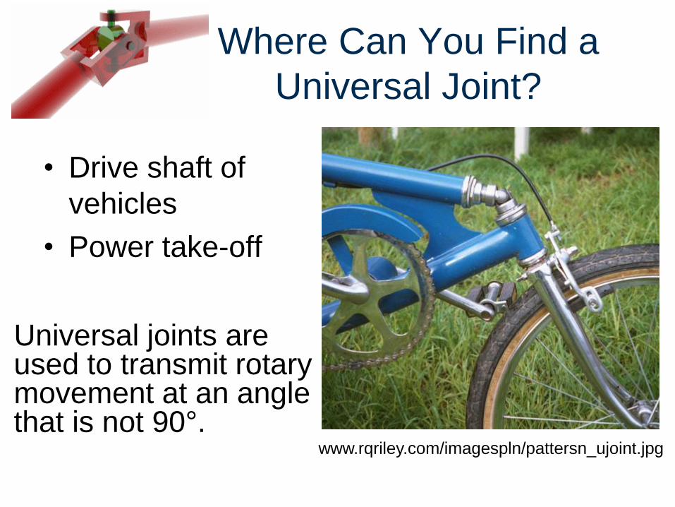
Universal Joint?
• Drive shaft of
vehicles
• Power take-off
www.rqriley.com/imagespln/pattersn_ujoint.jpg
Universal joints are used to transmit rotary movement at an angle that is not 90°.

Chain Drive
2. Angle is parallel
3. Speed is increased
4. Torque is decreased
5. Ratio 18:30 or 3:5
6. Smaller drive gear –
Speed – decreased
Torque - increased
7. Shaft direction
same
Driven
Drive
Drive
Driven

Where Do You Find a
Chain and Sprocket?
9. Advantage of Chain and
Sprocket over spur gears:
Transfer torque and speed
over long distances
8. Found in:
• Bicycle
• Motorcycle

Belt Drive
2. Shafts
parallel
3. Speed
constant
4. Torque
constant
5. Ratio 1:1
6. Larger drive pulley
Speed – increased
Torque - decreased
7. Open belt – same direction
8. Crossed belt - opposite
Drive
Driven

Where Do You Find a
Pulley and Belt?
9. Found in:
• Lawn mower
• Car engine BELTS
10. Belts instead of
chains:
• Quieter
• Less expensive

Crank and Slider2. Input Movement
rotary
3. Output Movement reciprocating
4. Slider Moves
2 in. (or diameter of crank)
5. Increased Crank increased distance slider moves
6. Flow of Power not reversible
Slider
Crank

Where Do You Find a
Crank and Slider?
7. Found in:
• Steam train
• Internal combustion
engine

Cam and Follower
2. Input Movement
rotary
3. Output Movement
reciprocating
4. Follower moves up and
down 1 time for every
revolution of the crank
5. Flow of Power
not reversible
6. Direction of Travel
not reversible
CAM
FOLLOWER

Where Do You Find a
Cam and Follower?
• As a cam rotates, the
flat follower is raised
and lowered,
converting rotary
motion to reciprocating
(back and forth)
motion.
• The cam pictured here
would be reversible,
as it is symmetrical.
7. Found in:
Cam shaft

Image Resources
Microsoft, Inc. (2008). Clip Art. Retrieved from
http://office.microsoft.com/en-us/clipart/default.aspx