Mechanics 07
6
Drive of Weapon with Together Bound Barrels and Breeches JIRI BALLA Department of weapons and ammunition University of Defence Kounicova 65, 662 10 Brno CZECH REPUBLIC [email protected] http://www.unob.cz LUBOMIR POPELINSKY [email protected] http://www.unob.cz ZBYNEK KRIST [email protected] http://www.unob.cz Abstract: Eccentric crank mechanism used in a weapon with together bound barrels and breeches as an accelerator is an example of one performance of the high rate of fire weapon. The drive of this mechanism is made by means of the gases flowing from the barrel into the gas cylinder. Key-Words: Eccentric crank mechanism, breech, reduced mass, cylinder, gas vent, gas flow, equation of motion 1 Introduction In addition to two formerly known high rate of fire weapon principles – the revolver principle and the Gatling principle (i. e. the principle with rotating barrels) [1], [2] the third high rate of fire principle with together bound barrels and breeches has been created. The first weapon of this principle has been designed by the German designer Gast at the end of the World War I. It was 7.92mm aircraft machine gun with two recoiling barrels but it was not used in following years After the World War II this principle has been redesigned by Russian designers and thus the automatic cannons of the caliber 23 mm and 30 mm have been created. On the base of this principle Czech designers have designed 20mm aircraft cannon ZPL-20 utilizing the NATO cartridge 20x102 mm and the cannon was accepted in the armament of Czech Air Forces in the year 2004. Main advantages of the cannon are the low weight and relatively small dimensions at the high power of fire. Basic design features of the cannon, (see Fig. 1 and Fig. 2), are the gas operated drive accelerating the breech block carriers of both barrels, functional link of both carriers by a pinion ensuring their alternate motion (i. e. if the breech block carrier of the right barrel moves backwards, the carrier belonging to the left barrel moves forwards) and the utilization of the crank mechanism between the breech block and its carrier belonging to each barrel. Fig. 1 Principle of design features This crank mechanism together with the functional curve in the weapon casing ensures the continuous motion (without impacts) of the breech block when firing. The influence of the functional curve is transferred on the breech mechanism by means of the roller placed on the crank. This roller meshes with the curve. 2 Kinematics and dynamics of weapon At the beginning of the dynamic analysis of the weapon it is necessary to find the primary geometric relations between links, velocities, transmission functions and accelerations or derivatives of the transmission functions. Found reduced mass and its derivative enter into the equation of motion whose form can be written as 2 red red red d 0,5 d m m x x Q x + = ɺɺ ɺ (1) or red red red d 0,5 d m m x x Q t + = ɺɺ ɺ . (2) RECENT ADVANCES in APPLIED and THEORETICAL MECHANICS ISSN: 1790-2769 48 ISBN: 978-960-474-140-3
Transcript of Mechanics 07

Drive of Weapon with Together Bound
Barrels and Breeches JIRI BALLA
Department of weapons and ammunition University of Defence
Kounicova 65, 662 10 Brno CZECH REPUBLIC
[email protected] http://www.unob.cz
LUBOMIR POPELINSKY [email protected] http://www.unob.cz
ZBYNEK KRIST
[email protected] http://www.unob.cz
Abstract: Eccentric crank mechanism used in a weapon with together bound barrels and breeches as an accelerator is an example of one performance of the high rate of fire weapon. The drive of this mechanism is made by means of the gases flowing from the barrel into the gas cylinder.
Key-Words: Eccentric crank mechanism, breech, reduced mass, cylinder, gas vent, gas flow, equation of motion
1 Introduction In addition to two formerly known high rate of
fire weapon principles – the revolver principle and the Gatling principle (i. e. the principle with rotating barrels) [1], [2] the third high rate of fire principle with together bound barrels and breeches has been created. The first weapon of this principle has been designed by the German designer Gast at the end of the World War I. It was 7.92mm aircraft machine gun with two recoiling barrels but it was not used in following years
After the World War II this principle has been redesigned by Russian designers and thus the automatic cannons of the caliber 23 mm and 30 mm have been created. On the base of this principle Czech designers have designed 20mm aircraft cannon ZPL-20 utilizing the NATO cartridge 20x102 mm and the cannon was accepted in the armament of Czech Air Forces in the year 2004. Main advantages of the cannon are the low weight and relatively small dimensions at the high power of fire. Basic design features of the cannon, (see Fig. 1 and Fig. 2), are the gas operated drive accelerating the breech block carriers of both barrels, functional link of both carriers by a pinion ensuring their alternate motion (i. e. if the breech block carrier of the right barrel moves backwards, the carrier belonging to the left barrel moves forwards) and the utilization of the crank mechanism between the breech block and its carrier belonging to each barrel.
Fig. 1 Principle of design features
This crank mechanism together with the functional curve in the weapon casing ensures the continuous motion (without impacts) of the breech block when firing. The influence of the functional curve is transferred on the breech mechanism by means of the roller placed on the crank. This roller meshes with the curve.
2 Kinematics and dynamics of weapon At the beginning of the dynamic analysis of the weapon it is necessary to find the primary geometric relations between links, velocities, transmission functions and accelerations or derivatives of the transmission functions. Found reduced mass and its derivative enter into the equation of motion whose form can be written as
2 redred red
d0,5
d
mm x x Q
x+ =ɺɺ ɺ (1)
or
redred red
d0,5
d
mm x x Q
t+ =ɺɺ ɺ . (2)
RECENT ADVANCES in APPLIED and THEORETICAL MECHANICS
ISSN: 1790-2769 48 ISBN: 978-960-474-140-3
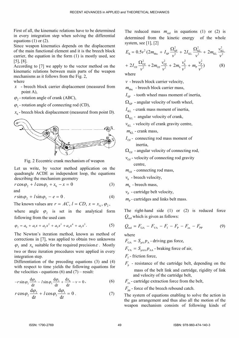
First of all, the kinematic relations have to be determined in every integration step when solving the differential equations (1) or (2). Since weapon kinematics depends on the displacement of the main functional element and it is the breech block carrier, the equation in the form (1) is mostly used, see [5], [8]. According to [7] we apply to the vector method on the kinematic relations between main parts of the weapon mechanisms as it follows from the Fig. 2, where x - breech block carrier displacement (measured from point A),
2ϕ - rotation angle of crank (ABC),
3ϕ - rotation angle of connecting rod (CD),
bx - breech block displacement (measured from point D).
Fig. 2 Eccentric crank mechanism of weapon
Let us write, by vector method application on the quadrangle ACDE as independent loop, the equations describing the mechanism geometry
2 3 bcos cos 0r l x xϕ ϕ+ + − = (3)
and
2 3sin sin 0r l eϕ ϕ+ − = . (4)
The known values are A 2, , ,r AC l CD x x ϕ= = = ,
where angle 2ϕ is set in the analytical form
following from the used cam
2 3 4 52 0 1 2 3 4 5a a x a x a x a x a xϕ = + + + + + . (5)
The Newton’s iteration method, known as method of corrections in [7], was applied to obtain two unknowns
3ϕ and bx suitable for the required precisionε . Mostly
two or three iteration procedures were applied in every integration step. Differentiation of the preceding equations (3) and (4) with respect to time yields the following equations for the velocities - equations (6) and (7) – result:
3 b22 3
d ddsin sin 0
d d d
xr l v
t t t
ϕϕϕ ϕ− − + − = , (6)
322 3
ddcos cos 0
d dr l
t t
ϕϕϕ ϕ+ = . (7)
The reduced mass redm in equations (1) or (2) is
determined from the kinetic energy of the whole system, see [1], [2]
2 2 22 SP KL KL
K bbc SP KL KL2 2 2
2 2 2 2OJ OJ b P
OJ OJ b P2 2 2 2
0.5 (2 2 2
2 2 2 ) (8)
vE v m I I m
v v v
v v vI m m m
v v v v
Ω Ω= + + +
Ω+ + + +
where
v - breech block carrier velocity,
bbcm - breech block carrier mass,
SPI - tooth wheel mass moment of inertia,
SPΩ - angular velocity of tooth wheel,
KLI - crank mass moment of inertia,
KLΩ - angular velocity of crank,
KLv - velocity of crank gravity centre,
KLm - crank mass,
OJI - connecting rod mass moment of
inertia,
OJΩ - angular velocity of connecting rod,
OJv - velocity of connecting rod gravity
centre,
OJm - connecting rod mass,
bv - breech velocity,
bm - breech mass,
Pv - cartridge belt velocity,
Pm - cartridges and links belt mass.
The right-hand side (1) or (2) is reduced force
redQ which is given as follows:
red GA VA f P ex PPQ F F F F F F= − − − − − (9)
where
GA pA AF S p= - driving gas force,
VA pAA AAF S p= - braking force of air,
fF - friction force,
pF - resistance of the cartridge belt, depending on the
mass of the belt link and cartridge, rigidity of link and velocity of the cartridge belt,
exF - cartridge extraction force from the belt,
ppF - force of the breech rebound catch.
The system of equations enabling to solve the action in the gas arrangement and thus also all the motion of the weapon mechanism consists of following kinds of
RECENT ADVANCES in APPLIED and THEORETICAL MECHANICS
ISSN: 1790-2769 49 ISBN: 978-960-474-140-3

equations, see [2]: equation of motion (1) and the other describing the function of the gas drive. These equations must be adapted for gases, for the air and for the other conditions (e.g. in dependence on the pressure ratio between the cylinder and the barrel. The action of the drive system utilizing the propellant gases must be solved for two periods depending on the relation of the pressure of gases inside the barrel bore pbl and the pressure of gases inside the gas cylinder „A“ pA, see [2], [3]. If pbl > pA then the propellant gases flow through the gas port from the barrel into the gas cylinder. For case pbl < pA the gases flow in the opposite direction. These two periods influence the equations of the gas flow in the following way. For pbl > pA: Equation of the energy change in the gas cylinder „A“
( ) ( ) ( )A A A bl A A A pA
d1
dp V kR G T G T k p S v
t= − − − (10)
Equation of the gas mass change in the gas cylinder „A“
AA cyA
A
d
d
VG G
t w
= −
. (11)
For pbl < pA : Equation of the energy change in the gas cylinder „A“
( ) ( ) ( )A A A A cyA A pA
d1 .
dp V kRT G G k p S v
t= − + − − (12)
Equation of the gas mass change in the gas cylinder „A“
( )AA cyA
A
d
d
VG G
t w
= − +
. (13)
Important characteristic of these equations is the magnitude of the gas mass flow G through any cross-section S from the state “1” to the state “2”. For the sub-critical flow it is given by the formula
2 11
21 2 2
1 1 1
2
1
k
k kp p pG S
k w p pµ
+ = − −
(14)
and for the critical flow by the formula
( )1
2 -11
1
2
1
k
k pG S k
k wµ
+
= − . (15)
In these two formulae is: µ - discharge coefficient, S – cross-section through the gas flows, k – ratio of specific heats, p1 – pressure in the vessel, from which the gas flows,
p2 – pressure in the vessel into which the gas flows, w1 – specific volume of the gas in the vessel from which the gas flows. The influence of the air being in the cylinder on the opposite site of the piston can be taken into consideration utilizing also the equations of the energy change and the mass change arranged for the air. Thus these equations for the air cylinder “A” are
( ) ( )
( )
AA AA A A AA AAch AAcl
A AA pAA
d
d1
p V k R T G Gt
k p S v
= − +
+ − (16)
( )AAAAch AAcl
AA
d
d
VG G
t w
= − +
. (17)
In addition to previous equations the solution of the action of gases in the gas cylinder “A” utilizes following equations: - instantaneous volume of the gas cylinder “A” is
A A0 pAV V S x= + , (18)
- instantaneous pressure of gases in the gas cylinder “A”
( )A A
AA
p Vp
V= , (19)
- instantaneous specific volume of gases in the gas cylinder “A”
AA
A
A
Vw
V
w
=
, (20)
- instantaneous temperature of gases in the gas cylinder “A”
A AA
p wT
R= . (21)
The solution of the action of the air in the air cylinder “A” utilizes similar equations:
AA AA0 pAAV V S x= − , (22)
AAAA
AA
AA
Vw
V
w
=
, (23)
AA AAAA
A
p wT
R= , (24)
( )AA AAAA
AA
p Vp
V= . (25)
Symbols used in previous equations are:
RECENT ADVANCES in APPLIED and THEORETICAL MECHANICS
ISSN: 1790-2769 50 ISBN: 978-960-474-140-3
pbl - pressure of gases in the barrel bore, pA - pressure of gases in the gas cylinder “A”, t - time, VA - instantaneous volume of the gas cylinder “A”. VA0 - initial volume of the gas cylinder “A” R - gas constant of propellant gases, GA - gas mass flow through the gas port, Tbl - temperature of gases in the barrel bore, GcyA - gas mass flow from the gas cylinder through the exhaust orifice, TA - temperature of gases in the gas cylinder “A”, SpA - area of the piston in the gas cylinder “A”, v - velocity of the piston,
bbcx x= - displacement of the piston,
wA - specific volume of gases in the gas cylinder “A”, pAA - pressure of the air in the air cylinder “A”, VAA - instantaneous volume of the air cylinder “A”, VAA0 - initial volume of the air cylinder “A”, kA - ratio of specific heats of the air, RA - gas constant of the air, GAAch - air mass flow from the air cylinder through the exhaust orifice, GAAcl - air mass flow from the air cylinder through the clearance of the piston rod, SpAA - area of the piston in the air cylinder “A”, wAA - specific volume of the air in the air cylinder “A”.
The system of differential equations was solved using the extrapolation method, published in [2] together with the equation of kinematics, see [7].
3 Results The results of calculation are presented onward. The numerical values of the input parameters belonging to the system were obtained from technical specifications and drawings. Due to very large numbers of inputs only the most important there are mentioned hereto. First of all, the significant kinematic values are:
0.065 m, 0.138 m, 0.0388 m,r l e= = =
bbc b oj
2 2KL OJ
2.4 kg, 0.18 kg, 0.14 kg,
0.0005304 kg.m , 0.001166 kg.m .
m m m
I I
= = =
= =
The inputs belonging to the gas drive were chosen according to design of the weapon and they were corrected with respect to the technical experiments. The main values are: SpA = 0.000706858 m2, µ = 0.524 if pbl > pA and µ = 0.01 if pbl < pA, k = 1.26, pbl = 161 MPa (beginning of the drive), R = 350, Thl = 2529 K, kA = 1.4,
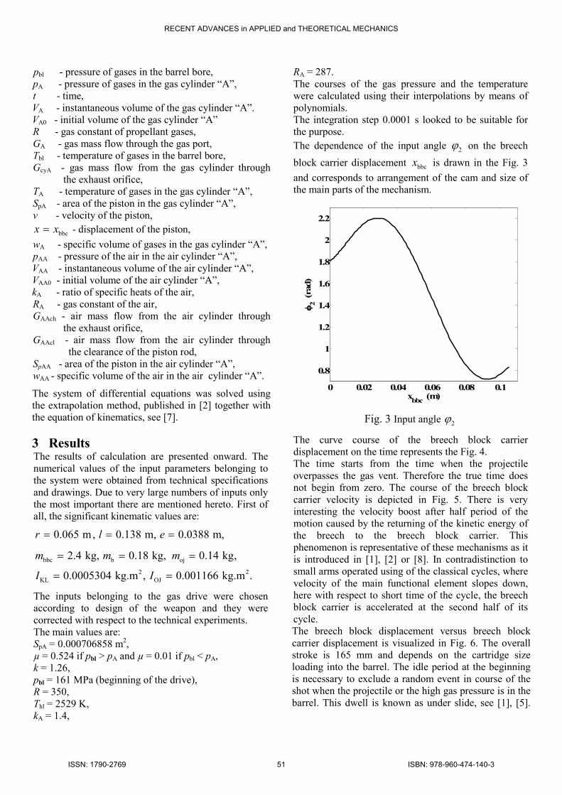
RA = 287. The courses of the gas pressure and the temperature were calculated using their interpolations by means of polynomials. The integration step 0.0001 s looked to be suitable for the purpose. The dependence of the input angle 2ϕ on the breech
block carrier displacement bbcx is drawn in the Fig. 3
and corresponds to arrangement of the cam and size of the main parts of the mechanism.
0 0.02 0.04 0.06 0.08 0.1
0.8
1
1.2
1.4
1.6
1.8
2
2.2
xbbc (m)
φφ φφ2 (rad)
Fig. 3 Input angle 2ϕ
The curve course of the breech block carrier displacement on the time represents the Fig. 4. The time starts from the time when the projectile overpasses the gas vent. Therefore the true time does not begin from zero. The course of the breech block carrier velocity is depicted in Fig. 5. There is very interesting the velocity boost after half period of the motion caused by the returning of the kinetic energy of the breech to the breech block carrier. This phenomenon is representative of these mechanisms as it is introduced in [1], [2] or [8]. In contradistinction to small arms operated using of the classical cycles, where velocity of the main functional element slopes down, here with respect to short time of the cycle, the breech block carrier is accelerated at the second half of its cycle. The breech block displacement versus breech block carrier displacement is visualized in Fig. 6. The overall stroke is 165 mm and depends on the cartridge size loading into the barrel. The idle period at the beginning is necessary to exclude a random event in course of the shot when the projectile or the high gas pressure is in the barrel. This dwell is known as under slide, see [1], [5].
RECENT ADVANCES in APPLIED and THEORETICAL MECHANICS
ISSN: 1790-2769 51 ISBN: 978-960-474-140-3
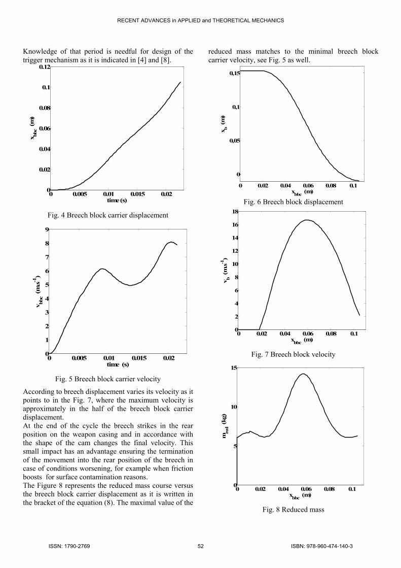
Knowledge of that period is needful for design of the trigger mechanism as it is indicated in [4] and [8].
0 0.005 0.01 0.015 0.020
0.02
0.04
0.06
0.08
0.1
0.12
time (s)
xbbc (m)
Fig. 4 Breech block carrier displacement
0 0.005 0.01 0.015 0.020
1
2
3
4
5
6
7
8
9
time (s)
vbbc (m.s-1)
Fig. 5 Breech block carrier velocity
According to breech displacement varies its velocity as it points to in the Fig. 7, where the maximum velocity is approximately in the half of the breech block carrier displacement. At the end of the cycle the breech strikes in the rear position on the weapon casing and in accordance with the shape of the cam changes the final velocity. This small impact has an advantage ensuring the termination of the movement into the rear position of the breech in case of conditions worsening, for example when friction boosts for surface contamination reasons. The Figure 8 represents the reduced mass course versus the breech block carrier displacement as it is written in the bracket of the equation (8). The maximal value of the
reduced mass matches to the minimal breech block carrier velocity, see Fig. 5 as well.
0 0.02 0.04 0.06 0.08 0.1
0
0,05
0,1
0,15
xbbc (m)
xb (m)
Fig. 6 Breech block displacement
0 0.02 0.04 0.06 0.08 0.10
2
4
6
8
10
12
14
16
18
xbbc (m)
vb (m.s-1)
Fig. 7 Breech block velocity
0 0.02 0.04 0.06 0.08 0.10
5
10
15
xbbc (m)
mred (kg)
Fig. 8 Reduced mass
RECENT ADVANCES in APPLIED and THEORETICAL MECHANICS
ISSN: 1790-2769 52 ISBN: 978-960-474-140-3

The differentiation of the reduced mass according to x was calculated numerically in every integration step. The course of the gas pressure in the gas cylinder (and it is the pressure on the driven piston connected with the breech block carrier) typifies the Fig. 9. The pressure is much lower than the initial gas pressure in the barrel when the mechanism operation begins. The force driving the whole mass creates during functional cycle the impulse equals to the momentum whereby all parts obtain the required velocities. The impulse course is drawn in the Fig. 10. At the end the system gains the maximal value. However, it is interesting that this high rate of fire weapons are driven within entire cycle in contrast to weapons whose rate of fire under 1000 rounds per minute. These weapons have the main functional elements accelerated in shorter time in consideration of the total functional cycle.
0 0.005 0.01 0.015 0.020
2
4
6
8
10
12
time (s)
pA (MPa)
Fig. 9 Gas pressure in cylinder
0 0.005 0.01 0.015 0.020
10
20
30
40
50
60
70
imp (N.s)
time (s)
Fig. 10 Impulse of gas force in cylinder
4 Conclusion The results given in the figures reflect a good coincidence with the real weapon which was design according to presented theory. The theory was verified on the other examples of weapons patterns as it is published in [2] for example. The course of input angle
2ϕ depending on the cam curve, see Fig. 3 and the
equation (5), seems to be more suitable than the curves used in the Gatling systems, which are presented in [2] or [8]. The procedure used in this article has been applied in the Czech research institutes and in the Defence University in Brno as additional teaching material for students of weapons and ammunition branch.
References:
[1]Allsop, D. F., Balla, J., Cech, V., Popelinsky, L., Prochazka, S., Rosicky, J. Brassey´s Essential Guide
to MILITARY SMALL ARMS. London,Washington. Brassey´s, 1997.
[2]Balla, J., Popelinsky, L. Vysokokadenční automatické
zbraně. (High rate of fire weapons). (Textbook). University of Defence. Brno (Czech Republic), 2004.
[3]Jedlicka, L., Beer, S., Videnka, M. Modelling of
pressure gradient in the space behind the projectile. In Proceedings of the 7th International Conference on System Science and Simulation in Engineering, Venice (Italy), November 21 – 23, 2008.
[4]Macko, M. A simulation of the sport small arms
trigger mechanisms. In 10th WSEAS Int Conf on Math Methods, Computat Tech and Intelligent Syst, OCT 26-28, 2008 Corfu, Greece 21 – 23, 2008.
[5]Vitek, R. Influence of the small arm barrel bore
length on the angle of jump dispersion. In Proceedings of the 7th International Conference on System Science and Simulation in Engineering, Venice (Italy), November 21 – 23, 2008.
[7] Brat, V., Rosenberg, J., Jac, V. Kinematika. (Kinematics). SNTL, Prague (Czechoslovakia), 1987.
[8] Racek, F., Baláž, T., Macko, M, Červenka, M. Measuring and modelling of initiation mechanisms of
small arms. Proceedings of the 9th WSEAS International Conference on Applied Computer science [ACS´09]. (Genova) Italy, October 17-18, 2009.
Acknowledgement
The work presented in this paper has been supported by the research projects: SV2009-K201, VZ FVT 402 and POV “DELO” 2009.
RECENT ADVANCES in APPLIED and THEORETICAL MECHANICS
ISSN: 1790-2769 53 ISBN: 978-960-474-140-3