Mechanically Stabilized Earthen (MSE) Berm Basics ...€¦ · Construction Quality Control ... AWT...
20
Mechanically Stabilized Earthen (MSE) Berm Basics – Applicability, Design Standards and Construction Quality Control/Assurance Carlton L. Dudding 1 , Scott K. Sheridan, PE 2 1 Advanced Wall Technologies, LLC, 4870 Sadler Road, Suite 300, Glen Allen, VA 23060, 2 Geosyntec Consultants, 9211 Arboretum Parkway, Suite 200, Richmond, VA 23236 Keywords: CCP, MSE, encapsulation, beneficial, reuse, disposal, airspace, expansion, regulation, landfill, construction, design, wet, dry, conversion, permitting Mechanically Stabilized Earth (MSE) berms have been utilized for many years in solid waste facilities for lateral and vertical expansion. New technologies have emerged that allow for the beneficial reuse of CCP’s to be utilized in the construction of these berms (encapsulated) both in the solid waste management and power generation industries. In the power industry these berms can be utilized in “dry” and “wet” systems, conversion of “wet” to “dry” systems and stabilization of in place structures (berms). While utilized for many years in certain industries, MSE berms and techniques are generally new to members of the power generation community. The need exists for the clear communication of essential design elements and factors as well as appropriate construction quality control and assurance measures. Careful adherence to these standards and principles can lead to successful project completion. Failure to do so can result in potentially catastrophic failures. Essential to this process is understanding the specific properties of construction materials (including CCP’s), their impacts on other materials specified for construction (geosynthetics, soil, etc.), appropriate construction techniques, and careful management of pore pressures particularly via encapsulated drainage systems during and after construction. AWT and Geosyntec Consultants have permitted multiple MSW landfill facility expansions using MSE berms. AWT is currently evaluating, permitting and preparing for construction multiple berms for landfill expansion using CCP’s. Numerous other projects are currently in various stages of development across the Eastern US using CCP’s. This paper describes and details the essential design, construction and drainage management issues.
-
Upload
doannguyet -
Category
Documents
-
view
215 -
download
0
Transcript of Mechanically Stabilized Earthen (MSE) Berm Basics ...€¦ · Construction Quality Control ... AWT...

Mechanically Stabilized Earthen (MSE) Berm Basics – Applicability, Design Standards and
Construction Quality Control/Assurance
Carlton L. Dudding1, Scott K. Sheridan, PE2 1Advanced Wall Technologies, LLC, 4870 Sadler Road, Suite 300, Glen Allen, VA 23060, 2 Geosyntec Consultants, 9211 Arboretum Parkway, Suite 200, Richmond, VA 23236 Keywords: CCP, MSE, encapsulation, beneficial, reuse, disposal, airspace, expansion, regulation, landfill, construction, design, wet, dry, conversion, permitting
Mechanically Stabilized Earth (MSE) berms have been utilized for many years in solid waste facilities for lateral and vertical expansion. New technologies have emerged that allow for the beneficial reuse of CCP’s to be utilized in the construction of these berms (encapsulated) both in the solid waste management and power generation industries. In the power industry these berms can be utilized in “dry” and “wet” systems, conversion of “wet” to “dry” systems and stabilization of in place structures (berms). While utilized for many years in certain industries, MSE berms and techniques are generally new to members of the power generation community. The need exists for the clear communication of essential design elements and factors as well as appropriate construction quality control and assurance measures. Careful adherence to these standards and principles can lead to successful project completion. Failure to do so can result in potentially catastrophic failures. Essential to this process is understanding the specific properties of construction materials (including CCP’s), their impacts on other materials specified for construction (geosynthetics, soil, etc.), appropriate construction techniques, and careful management of pore pressures particularly via encapsulated drainage systems during and after construction. AWT and Geosyntec Consultants have permitted multiple MSW landfill facility expansions using MSE berms. AWT is currently evaluating, permitting and preparing for construction multiple berms for landfill expansion using CCP’s. Numerous other projects are currently in various stages of development across the Eastern US using CCP’s. This paper describes and details the essential design, construction and drainage management issues.

1.0 INTRODUCTION The number of mechanically stabilized earth (MSE) berms used at landfills and power generation facilities has increased significantly in the United States while the overall number of landfills has declined significantly. The clear and simple reason is that it is far harder to obtain new waste management facility permits than to obtain amendments to existing permits. Higher regulatory standards and local resistance to permitting landfills in the proximity of other development have accelerated this decline, thus increasing the value of permitted landfills and the tipping fees to customers. As the remaining landfills reach capacity, the need for innovative, cost-effective methods for creating new airspace has intensified. Greatly increased regulatory pressure is anticipated to be exerted on the coal fired utility industry in the management of their coal combustion products (CCP’s) and the conversion of wet to dry disposal management. In this paper the authors examine the vertical expansion of waste facilities, new technologies to manage these expansions, and application of these technologies at specific projects currently under consideration and construction in the eastern United States. The applicability and practicality of these engineered systems, the design standards upon which they are engineered, and the construction quality control and assurance practices used to confirm proper construction are evaluated. The failure to adhere to sound principles can result in seriously flawed constructed systems and can, in fact, lead to failure.
The beneficial reuse of CCP’s and their encapsulation is a major component of the technology. The usage of CCP’s allows the CCP generator to expand its disposal facilities, increase basin capacity or constructing road or other embankments using their own CCP material as construction material. Additionally, the use of CCP’s can allow those facilities that have no room for lateral expansion to export their material to expand other solid waste facilities via beneficial reuse of their CCP’s (a typical AWT encapsulated berm project utilizes
500,000-2,000,000 CY’s of material). To make vertical and lateral expansions more economically feasible, AWT developed patented and patent(s) pending designs for construction of MSE berms with an encapsulated section using backfill materials that are environmentally and regulatory agency acceptable. The AWT technology is a less expensive alternative than a lateral expansion because the large capital expenditures for property and infrastructure development are eliminated. Additionally, AWT technology can be utilized for other embankment scenarios in which utilizing materials that are currently not allowable for construction would be deemed beneficial reuse.

2.0 BACKGROUND MSE berms are common throughout the entire United Sates. They are used extensively in all states on highway projects, at large retail and commercial/industrial construction projects (usually vertical masonry block) and increasingly at landfills and power generation facilities for waste disposal expansion (generally vegetated berms), ancillary facility development, road embankments and for wet basin expansion or closure. Below are a few interesting statistics.
FHWA estimates since 1972, more than 8,000 MSE berms with heights up to 140 ft. have been constructed throughout the U.S. They have been used for:
road embankments, bridge abutments, wing walls, crash walls, landslide repairs, pedestrian ramps, and other applications where steepened embankments or walls are needed,
such as perimeter berms around landfills.
140-foot wall – Seattle-Tacoma International Airport needed a third runway, so they constructed the tallest modern MSE berm.
A fundamental component of the innovative solution presented herein is the use of MSE technology. This technology as applied to waste containment facilities consists of utilizing geosynthetic reinforcing elements in combination with soil and a wide selection of facing elements to create safe, cost-effective grade separations for waste containment facilities.

MSE technology is well established: the first geosynthetically-reinforced grade separation structure worldwide was completed in France in 19731 and in North America in Oregon in 19742. In 1985, MSE technology was used for the first time in North America to create useful airspace within a waste containment facility3. MSE technology using geosynthetic reinforcement was introduced to the municipal solid waste market in 1996, with the design and construction of the first MSE berm at Pottstown Landfill in Pottstown, PA4. Since 1996, MSE berms have been constructed at 11 different landfills in Pennsylvania alone, with additional construction occurring in New York, Georgia, Maine, New Hampshire, Delaware, Maryland, Massachusetts, Florida, Alabama, Louisiana, Virginia, and Kentucky.
During Landfill Construction After Filling With Waste
Continued use of accepted design guidelines, along with a preponderance of literature on all aspects of MSE berms including stability5; 6 and construction aspects7, and the flexibility of expansion options, have created an environment in which the use of MSE berms will continue into the foreseeable future.


Their use however is not without pitfalls. In December 2009, the Geosynthetics Institute (GRI), the acknowledged leader in independent geosynthetics research, issued GRI Report No. 38 on wall failures8. It concluded that the majority of failures were the result of:
Improper design
Improper construction techniques. Further it noted that:
All of the failures observed were private but NONE occurred in a landfill berm.
Masonry block walls accounted for 76% of failures.
Design engineer responsible for 65% of failures.
Contractor responsible for 33% of failures
68% of failures were internal or external water related
80% of failures were due to moderate to poor compaction of material used in berm construction.
Final conclusions of the report were as follows:
1. Proper compaction is absolutely critical to maintain stability, and
2. Proper control of both surface water and water internal to the berm is also critical to maintaining berm stability.
Other important findings from the report are listed below.
The authors of this paper would add that when designers do not understand the systems they are designing, when input from experienced designers is not allowed during construction, and when proper construction quality assurance is not performed the project may have a greatly increased likelihood of failure.
The authors of this paper also strongly believe that a berm properly designed, properly constructed, and properly managed for water internal and external to the berm result in one of the most useful methods for waste and CCP management that has emerged in the last twenty (20) years.
The great majority of berms constructed at waste and power facilities are vegetated berms eliminating the possibility of masonry block walls which account for 76% of failures.

States with Permitted or Planned Landfill MSE Berms
There has never been a substantive failure of a Landfill MSE Berm in the United States
3.0 VERTICAL EXPANSION DESIGN CHALLENGES, CONSIDERATIONS & SOLUTIONS In general, the placement of additional waste material over previously placed material (vertical expansion) encompasses many unique challenges and design considerations that are discussed in the following sections: 3.1 Piggybacking of Liner Systems Where Required “Piggybacking” is the term generally given to the practice of placing additional waste over top of existing waste whether it is MSW, construction & demolition debris, industrial or CCP materials. Each of these materials has their own unique characteristics. Regulatory agencies generally require a consolidation analysis and may require additional liner systems placed between the vertical expansion materials and existing waste mass. On one recently completed landfill project, a portion of the waste mass did not include base liner or leachate collection systems, and therefore, a piggyback liner system was required. An extensive geotechnical investigation was implemented to determine settlement and strength parameters of the waste and potential void locations with the goal of designing a liner system that would withstand the strains induced by overfilling the existing waste mass.

3.2 Existing and Future Property Limitations Many sites, particularly in developed areas, have severe inherent limitations that hamper, if not eliminate, lateral expansion. These include the encroachment of industrial, commercial or residential areas on the site since the facility was originally constructed, limitations due to the locations of streams and/or wetlands adjacent to the waste management areas and the permitting difficulties and expanded permitting timelines resulting from their presence. In addition, most solid waste management regulations have very specific setbacks from property boundaries, wetlands, streams, residences, 100 year floodplains, etc.
3.3 Appropriate Geogrid Reinforcement MSE berms use geogrids to reinforce the soil used in construction to create a stable berm. Moreover, it is the geogrid component that allows for the construction of a near vertical exterior wall that facilitates the largest amount of airspace without expanding laterally. Therefore, careful consideration must be given to the type, spacing and manufacturer/supplier of geogrid to provide a finished product that functions as designed.

AWT Vertical Encapsulated Expansion Berm-Patent & Patents(s) Pending Design
Geogrids stabilize the MSE berm against multiple potential failure modes including external and internal stability and differential settlement. At a recently completed landfill project the limited space required the location of a portion of the MSE berm over the MSW waste mass, leading to significant differential settlement. The lower layers of geogrid were designed with a higher ultimate strength than the upper layers and were extended to mitigate the impacts of the calculated differential settlement and to increase the factor of safety for the global stability of the berm. Internal friction angle and gradation of material is critical – technical specifications must be flexible and adherence to them is essential. Following are example tables from design specifications for Uniaxial (Example Table 1) and Biaxial (Example Table 2) geogrids and Soil/CCP Materials (Example Table 3). As mentioned above, geogrid reinforcement is designed to account for both external and internal stability. Typical factors of safety for various failure modes that are both external and internal to the berm are indicated in the figure following the example tables. In addition, illustrations of typical geogrid reinforcement and facing materials are provided below.

EXAMPLE TABLE 1
STRUCTURAL GEOGRID TESTING
PROPERTIES QUALIFIERS UNITS SPECIFIED
VALUES TEST
METHOD QC
FREQUENCY QA
FREQUENCY
Ultimate Tensile Strength (Low-strength)
Minimum lb/ft 7,810 ASTM D
6637 Every 50,000 sf
Every 100,000 sf
Allowable Tensile Strength (Low-strength)
Minimum lb/ft 2,860 ASTM D
6637
Based on certification with
lab data
N/A
Ultimate Tensile Strength (Moderate-strength)
Minimum lb/ft 11,990 ASTM D
6637 Every 50,000 sf
Every 100,000 sf
Allowable Tensile Strength (Moderate-strength)
Minimum lb/ft 4,390 ASTM D
6637
Based on certification with
lab data
N/A
Ultimate Tensile Strength (High-strength)
Minimum lb/ft 14,390 ASTM D
6637 Every 50,000 sf
Every 100,000 sf
Allowable Tensile Strength (High-strength)
Minimum lb/ft 5,329 ASTM D
6637
Based on certification with
lab data
N/A
Interface Friction Angle (Low, Moderate, and High Strength)
Minimum
Degrees
20 ASTM D
5321 N/A
Every 100,000 sf
EXAMPLE TABLE 2
WRAP GEOGRID TESTING
PROPERTIES QUALIFIERS UNITS SPECIFIED
VALUES TEST
METHOD QC
FREQUENCY QA
FREQUENCY
Ultimate Tensile Strength
Minimum lb/ft2 1,300
ASTM D 6637
Every 100,000 sf
Every 250,000 sf
Long-term allowable Tensile Strength
Minimum lb/ft2 400
ASTM D 6637
Based on certification with lab data
N/A
UV Resistance at 500 hours
Minimum Percent 99 ASTM D
4355
Based on certification with lab data
N/A

EXAMPLE TABLE 3
MINIMUM TESTING FREQUENCIES
FOR LABORATORY SOIL EVALUATION
TEST METHOD MINIMUM FREQUENCY OF
TESTING (1) ALLOWABLE RANGE
Grain Size Analysis
(Sieve and Hydrometer) ASTM D 422
1 per 10,000 yd3
(minimum 1 test per material
type and source)
NA
Moisture Content ASTM D 2216
1 per 10,000 yd3
(minimum 1 test per material
type and source)
NA
Atterberg Limits ASTM D 4318
1 per 10,000 yd3
(minimum 1 test per material
type and source)
NA
Standard Proctor ASTM D 698
1 per 10,000 yd3
(minimum 1 test per material
type and source)
Maximum Unit Weight Range
@ 95% Compaction = 70 to 90
pcf
Hydraulic Conductivity
ASTM D 2434 or
ASTM D 5084
(4)
1 per 10,000 yd3
(minimum 1 test per material
type and source)
Maximum HC = 1X10⁻⁷ cm/sec
Organic Content (2) ASTM D 2974
1 per 10,000 yd3
(minimum 1 test per material
type and source)
Maximum OC = 10%
Internal Angle of
Friction ASTM D 3080
1 per 25,000 yd3
(minimum 1 test per material
type and source)
Minimum Range = 30 to 33
Degrees
Interface Friction Angle
(3) ASTM D 5321
1 per 25,000 yd3
(minimum 1 test per material
type and source)
Minimum Range = 17 to 20
Degrees


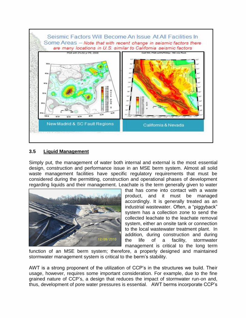
3.4 Seismic Analysis Seismic impact zones are defined as those areas with a ten percent or greater probability that the maximum horizontal acceleration (MHA) in lithified earth material, expressed as a percentage of the earth's gravitational pull (g), will exceed 0.10g in 250 years. With the update of National Seismic Hazard Maps developed by the United States Geological Survey additional areas have been identified as seismic impact zones that had previously not been included. Example maps are presented below. MSE berms can be designed to withstand seismic events with proper geogrid reinforcement design and control of internal pore water pressure. Failure of MSE berms due to seismic events will generally occur through global slope failure, internal slope failure, or seismic liquefaction. Slope failures can be satisfactorily accounted for in the MSE berm design through the proper design of the geogrid reinforcement. Liquefaction can be accounted for through the specification of granular soils and the control of internal pore water pressure. Encapsulated MSE berm system provide control of internal pore water pressure by preventing water from entering the system, thus allowing for a more flexible range of usable backfill.
3.5 Liquid Management Simply put, the management of water both internal and external is the most essential design, construction and performance issue in an MSE berm system. Almost all solid waste management facilities have specific regulatory requirements that must be considered during the permitting, construction and operational phases of development regarding liquids and their management. Leachate is the term generally given to water
that has come into contact with a waste product, and it must be managed accordingly. It is generally treated as an industrial wastewater. Often, a “piggyback” system has a collection zone to send the collected leachate to the leachate removal system, either an onsite tank or connection to the local wastewater treatment plant. In addition, during construction and during the life of a facility, stormwater management is critical to the long term
function of an MSE berm system; therefore, a properly designed and maintained stormwater management system is critical to the berm’s stability. AWT is a strong proponent of the utilization of CCP’s in the structures we build. Their usage, however, requires some important consideration. For example, due to the fine grained nature of CCP’s, a design that reduces the impact of stormwater run-on and, thus, development of pore water pressures is essential. AWT berms incorporate CCP’s

and fully encapsulate the CCP’s in a liner system to reduce the likelihood of leachate and/or stormwater from entering or exiting the system, leading to long term stability, safety and reliability. In 2011, GRI issued GRI-345, regarding the importance of drainage control in wall systems9. Specifically the paper detailed the overwhelming necessity to maintain and design for proper drainage control in these systems and prevent problems. It concludes, “Thus it is seen that the entire reinforced soil zone must be encapsulated by waterproofing from above the drainage from beneath and behind whatever backfill consists of fine-grained soils. These precautions are felt to be absolutely necessary to prevent wall drainage failures from occurring in the future”. As indicated above in the GRI report No. 38, 68% of failures were internal or external water related. 3.6 Typical Design Elements Typically, an MSE berm design should include the following: Geotechnical Field Analysis:
Borings with split spoon sampling and Standard Penetration Tests every five feet (this assumes one boring every 100 feet along the wall alignment)
Triaxial shear strength tests;
Consolidation tests;
Unconfined compression tests; and
Atterberg Limits and grain size analyses
MSE Berm - Stormwater
Stormwater Management System Design;
Runoff Routing from Final Cover to Ponds;
Channel/Drop Inlet Design on Berm; MSE Berm Design
Berm Height Evaluation;
Final Cover Grades Conceptual Design;
Alignment Selection (Horizontal & Vertical);
Material Selection and Specification;
Cross Sections;
Geotechnical (Final, Interim, etc.) Analyses; o MSE Berm Settlement Analysis,
o MSE Berm Internal Stability Analysis,
o MSE Berm External Stability Analysis (static and seismic), and
o MSE Berm Liquefaction Analysis,
MSE Berm Phased Development Plans.

Permit Application
MSE Berm Design Report;
Drawings for MSE Berm;
Calculations for MSE Berm Design;
Specification and CQA Plan for MSE Berm; 4.0 CONSTRUCTION QUALITY CONTROL Construction Quality Control (CQC) refers generally to those actions taken by a contractor, manufacturer, or supplier, including their designated representatives to ensure that the materials and workmanship meet the requirements as established in the project drawings, technical specifications, CQA plan and all the components of the anticipated contract documents. Construction quality control is an increasingly important concern as defects or failures in constructed facilities can result in very large costs. As with cost control, the most important decisions regarding the quality of a completed facility are made during the design and planning stages rather than during construction. It is during these preliminary stages that component configurations, material specifications and functional performance are decided. Quality control during construction consists largely of insuring conformance to the original design and planning decisions. With the attention to conformance as the measure of quality during the construction process, the specification of quality requirements in the design and contract documentation becomes extremely important. Quality requirements should be clear and verifiable, so that all parties in the project can understand the requirements for conformance. Key Components to a proper CQC Plans include:
Technical Drawings;
Technical Specifications; and
Materials testing procedures and quantities. 5.0 CONSTRUCTION QUALITY ASSURANCE A robust Construction Quality Assurance (CQA) plan establishes the construction quality assurance observation and documentation activities that will be implemented during construction. The purpose of the CQA plan is to provide specific procedures that will be followed by CQA personnel in order to ensure the Owner and the regulatory agency that the construction was performed in accordance with the drawings and technical specifications. A CQA plan does NOT address design guidelines, installation specifications or procurement of materials required for construction. Construction Quality Assurance is best performed by someone independent of the owner, contractor, and manufacturer and materials installers. Experienced CQA personnel are critical for successfully implementing the CQA Plan for MSE berm construction. While the CQA Plan provides details related to the observation and documentation activities, the thorough understanding of MSE berm construction

and the construction details that are critical to watch by an experienced CQA monitor complement the requirements of a CQA Plan to ensure the proper construction of an MSE berm. Items that require close attention by a CQA inspector include, but are not limited to, the following:
Appropriate subgrade preparation;
Relocation and abandonment of existing structures;
Fill compaction;
Appropriate moisture conditioning of the fill;
Changes in fill properties that may require additional testing;
Consistent, acceptable facing installation procedures;
Installation of appropriate reinforcement at appropriate locations;
Verification of material properties against design requirements; and
Appropriate protection against run-on and run-off. With AWT designed MSE berms, experience with geosynthetic liner systems is key for a successful construction project. Using experienced, qualified CQA personnel who can appropriately implement the requirements of the CQA Plan will help ensure a successful construction project that satisfies the requirements of the design and will receive regulatory agency approval for operation. 6.0 CONSTRUCTION Construction of an MSE berm involves two basic functions: earth moving with heavy equipment and berm reinforcement and facing installation with manual labor. Because landfills are typically regulated structures, construction quality assurance of the materials and construction procedures is required. Therefore, coordinated efforts between the contractor, owner, designer, and construction quality assurance engineer are an important part of the success of MSE berm construction. AWT, Geosyntec, and Tensar Corporation have worked together with the earthworks contractor through the routine and the sometimes challenging portions of the berm construction to provide the owner with the airspace they need to continue landfill operation. The challenging portions of berm construction invariably involve discovering site conditions that were previously unknown and must be accounted for in the MSE berm design. Accounting for these unknowns in such a way that maintains the design and construction standards for the project is most easily accomplished through an experienced design, construction, and CQA team.

7.0 PUTTING IT ALL TOGETHER – THE CONSTRUCTED PRODUCT
AWT/Geosyntec Vertical Encapsulated Expansion Berm
The berm shown is 55’ high and constructed of CCP’s and contaminated soil.
The vertical expansion berm recently withstood a 5.8 – 6.0 (Richter Scale) earthquake.
Three days later it withstood Hurricane Irene impacts of 7-8” of rain in a 12-hour period coupled with 65 mph wind gusts and 45 mph sustained winds.
Upon follow-up inspections NO impacts were noted either from the earthquake or the hurricane remnants.
How is that Possible?
Proper Design, Construction Quality Control (CQC) and Construction Quality Assurance (CQA).
Internal and external drainage were controlled (uses AWT patented internal drainage system that are proactive in removing liquids).
Liquid/Pore Pressure Management! No liquids = No liquefaction. Encapsulation eliminates moisture and uniaxial geogrid adds stability. Any Berms constructed with CCP’s or non-cohesive material and no
encapsulation do not offer this important protection. 8.0 CONCLUSIONS MSE berms are common throughout the entire United States. They are used extensively in all states on highway projects, at large retail and commercial/industrial construction projects (usually vertical masonry block) and increasingly at landfills and power generation facilities for waste disposal expansion (generally vegetated berms), ancillary facility development, road embankments and for wet basin expansion or closure. Continued use of accepted design guidelines, along with a preponderance of literature on all aspects of MSE berms including stability and construction aspects, and the flexibility of expansion options, have created an environment in which the use of MSE berms will continue into the foreseeable future.

MSE berms have been used as an expansion technique where property constraints prevent lateral expansion or vertical expansion with non-reinforced berms. MSE berms are designed with reinforced earthen material(s) and provide significant grade changes in a limited space. The primary cost component of MSE berms is the procurement, transport, placement and compaction of the fill. Thus, any technique that minimizes the cost of this component can dramatically improve the economic benefits offered by MSE berms. To make vertical expansions more economically feasible, AWT developed a design for construction of these berms using backfill materials that are more economical to purchase (or sometimes are free or generate additional revenue) and deliver to the facility while being environmentally and regulatory agency acceptable. In general, the AWT technology is a less expensive alternative than a lateral expansion because the large capital expenditures for property and infrastructure development are eliminated. Additionally, the AWT technology can be utilized for other embankment scenarios (roads, etc.) in which utilizing materials that are currently not allowable for construction would be beneficial. Regulation changes are proposed and will be made public in the near future by the United States Environmental Protection Agency (USEPA) that will impact the means by which U.S. power generation companies manage CCP’s. These regulations will likely impact companies that own and operate both wet ash ponds and dry ash landfills. Power generation companies now have the creative solution via AWT encapsulated berm technology to ensure their CCP management costs remain relatively unaffected. In addition they can export their CCP’s for expansion of other landfills reducing long term liability, transportation and disposal costs. Power generation companies will have an option to increase their limited and critical airspace or basin storage capacity in a safer, less costly manner. 9.0 REFERENCES
1. Leflaive, E. (1988). Durability of Geotextiles: The French Experience”, Geotextiles and Geomembranes, Vol. 7, Nos. 1-2, 23-31.
2. Greenway, D., Bell, J.R., and Vandre, B. (1999). “Snailback Wall - First Fabric
Wall Revisited at 25 Year Milestone”, Proc. of Geosynthetics ’99, IFAI, Vol. 2, Boston, Massachusetts, USA, April 1999, 905-919.
3. Seawell, H and Mattox, R.M. (1987). “An Economical Solution to Increasing the
Capacity of an Industrial Waste Facility with a Geogrid Reinforced Dike”, Proc. Geosynthetics ’87, New Orleans, USA, pp. 341-352.
4. Ballod, C. and Brown, D. (2008). “Mechanically Stabilized Earth Berms:
Overview at Pennsylvania Landfills”, Proc. 2008 Global Waste Management Symposium, Copper Mountain, CO.
5. Luettich, S. and Quiroz, J. (2008). “Landfill Stability Analyses for the Application of Mechanically Stabilized Earth (MSE) Perimeter Berms”, Proc. 2008 Global Waste Management Symposium, Copper Mountain, CO.
6. Qian, X. and Koerner, R.M. (2009). “Stability Analysis When Using an
Engineered Berm to Increase Landfill Space”, J. Geotech. And Geoenviron. Engr., Vol. 135, No. 8, August, pp. 1082-1091.
7. Brown, D. and Ballod, C. (2008). “Construction Details and Related
Considerations of MSE Berms at Landfills”, Proc. 2008 Global Waste Management Symposium, Copper Mountain, CO.
8. Koerner, R and Koerner, G. (2009). “A Data Base and Analysis of Geosynthetic
Reinforced Wall Failures”, Geosynthetics Research Institute Report No. 38.
9. Koerner, R and Koerner, G. (2011), “The Importance of Drainage Control For Geosynthetic Reinforced Mechanically Stabilized Earth Wall”, GRI-345 Journal of GeoEngineering.


![Sediment Management - Geosyntec · Sediment Management 4UBUFNFOUPG2VBMJmDBUJPOT] About Geosyntec Section 1 About Geosyntec Technical Excellence, Teamwork and A Generous Spirit Recognized](https://static.fdocuments.in/doc/165x107/5d5dcc7788c993a30e8b8011/sediment-management-sediment-management-4ubufnfoupg2vbmjmdbujpot-about-geosyntec.jpg)