MECHANICALLY STABILIZED EARTH WALL · PDF fileMECHANICALLY STABILIZED EARTH WALL SYSTEM ......
45
MECHANICALLY STABILIZED EARTH WALL INSPECTOR'S HANDBOOK by: Paul D. Passe, P.E., CPM, September, 2000 Revised by: Juan F. Castellanos, P.E, June 2012.
Transcript of MECHANICALLY STABILIZED EARTH WALL · PDF fileMECHANICALLY STABILIZED EARTH WALL SYSTEM ......

MECHANICALLY
STABILIZED
EARTH
WALL
INSPECTOR'S HANDBOOK
by: Paul D. Passe, P.E., CPM, September, 2000
Revised by: Juan F. Castellanos, P.E, June 2012.
TABLE OF CONTENTS
I. INTRODUCTION. ....................................................................................................................................................... 1
II. TERMS ...................................................................................................................................................................... 2
III. MECHANICALLY STABILIZED EARTH WALL SYSTEM ................................................................................................... 3
IV. FOUNDATION PREPARATION ................................................................................................................................ 3
V. LEVELING PAD ........................................................................................................................................................... 4
VI. PANELS AND PANEL PLACEMENT .......................................................................................................................... 5
VII. WALL PANEL SPACERS .......................................................................................................................................... 7
PANEL PLACEMENT ............................................................................................................................................................... 8 SPECIAL PANELS .................................................................................................................................................................... 9 WOODEN WEDGES ....................................................................................................................................................... 10 PANEL STORAGE .................................................................................................................................................................. 11
VIII. SOIL REINFORCEMENT ........................................................................................................................................ 12
METALLIC REINFORCEMENT (INEXTENSIBLE ....................................................................................................................... 13 POLYMERIC (GEOSYNTHETICS)-EXTENSIBLE REINFORCEMENT ............................................................................................... 13 VERTICAL AND HORIZONTAL OBSTRUCTIONS ..................................................................................................................... 14 REINFORCEMENT STORAGE ..................................................................................................................................... 16 WALL/REINFORCEMENT CONNECTION .............................................................................................................................. 16
IX. FILTER FABRIC AND JOINTS ..................................................................................................................................... 17
X. COPING/BARRIER ................................................................................................................................................... 18
XI. ABUTMENT CHEEK WALLS ...................................................................................................................................... 19
XII. SELECT MSE WALL BACKFILL ............................................................................................................................... 20
PLACING BACKFILL .............................................................................................................................................................. 21 COMPACTION ..................................................................................................................................................................... 21 DAYS END ............................................................................................................................................................................ 22
XIII. MISCELLANEOUS POINTS .................................................................................................................................... 23
CONSTRUCTION LOADS....................................................................................................................................................... 23 DRAINAGE STRUCTURES ..................................................................................................................................................... 24 EXCAVATIONS ADJACENT TO MSE WALLS ........................................................................................................................... 25 TEMPORARY WALLS ............................................................................................................................................................ 26 TEMPORARY WALL FACING ................................................................................................................................................ 26
XIV. CONSTRUCTION .................................................................................................................................................. 27
APPENDIX A .................................................................................................................................................................... 36
CHECK LIST .......................................................................................................................................................................... 36
APPENDIX B ...................................................................................................................................................................B-1
MSE WALL CONSTRUCTION DO'S AND DON'TS ................................................................................................................. B-1
APPENDIX C .................................................................................................................................................................... C-1
OUT-OF-TOLERANCE CONDITIONS AND POSSIBLE CAUSES CRITERIA .............................................................................. C-1

This page intentionally blank

1
I. INTRODUCTION.
This handbook is designed for the CEI personnel and inspectors that will be involved and responsible
for inspecting the construction of mechanically stabilized earth (MSE) walls. It will provide general
guidelines for inspection; however, the plans, specifications and special provisions govern and must
be read and followed.
.
Figure 1, Wall Components
2
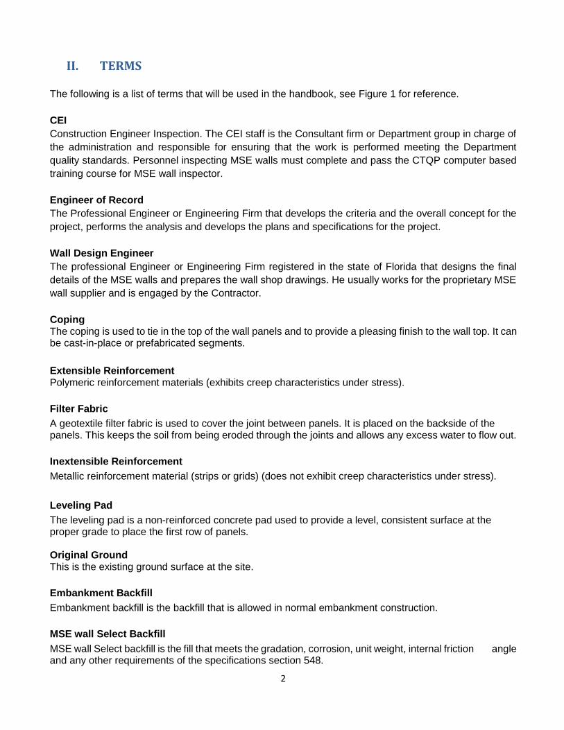
II. TERMS
The following is a list of terms that will be used in the handbook, see Figure 1 for reference.
CEI
Construction Engineer Inspection. The CEI staff is the Consultant firm or Department group in charge of
the administration and responsible for ensuring that the work is performed meeting the Department
quality standards. Personnel inspecting MSE walls must complete and pass the CTQP computer based
training course for MSE wall inspector.
Engineer of Record
The Professional Engineer or Engineering Firm that develops the criteria and the overall concept for the
project, performs the analysis and develops the plans and specifications for the project.
Wall Design Engineer
The professional Engineer or Engineering Firm registered in the state of Florida that designs the final
details of the MSE walls and prepares the wall shop drawings. He usually works for the proprietary MSE
wall supplier and is engaged by the Contractor.
Coping The coping is used to tie in the top of the wall panels and to provide a pleasing finish to the wall top. It can be cast-in-place or prefabricated segments.
Extensible Reinforcement Polymeric reinforcement materials (exhibits creep characteristics under stress).
Filter Fabric
A geotextile filter fabric is used to cover the joint between panels. It is placed on the backside of the panels. This keeps the soil from being eroded through the joints and allows any excess water to flow out.
Inextensible Reinforcement
Metallic reinforcement material (strips or grids) (does not exhibit creep characteristics under stress).
Leveling Pad
The leveling pad is a non-reinforced concrete pad used to provide a level, consistent surface at the proper grade to place the first row of panels. Original Ground This is the existing ground surface at the site.
Embankment Backfill
Embankment backfill is the backfill that is allowed in normal embankment construction.
MSE wall Select Backfill
MSE wall Select backfill is the fill that meets the gradation, corrosion, unit weight, internal friction angle and any other requirements of the specifications section 548.

3
Soil Reinforcement
Soil reinforcement holds the wall facing panels in position and provides reinforcement for the soil. The soil reinforcement can be strips, grids, geogrids or geotextiles. The reinforcement can be made of steel (inextensible materials) or polymers (extensible materials).
Spacers
Wall panel spacers are typically ribbed elastomeric or polymeric pads (bearing pads). They are inserted between panels to help provide the proper spacing. Proper spacing keeps the panels from having point contact and spalling the concrete.
Wall Facing Panel
Wall Facing panels or panels are used to hold the soil in position at the face of the wall. The panels are typically concrete but they can be metal, wood, block, mesh or other material.
Wall/Reinforcement Connection
This is where the connection is made between the wall facing panel and the soil reinforcing.
Water
The water described here is that which may be necessary for bringing the select backfill material up to optimum moisture content. It shall meet the electro-chemical properties required by the specifications.
Wooden Wedges
Wooden wedges are used to help hold the panels at the correct batter during the filling operation. The wooden wedges should be made from hard wood (such as oak, maple or ash).
III. MECHANICALLY STABILIZED EARTH WALL SYSTEM The wall system consists of the original ground, concrete leveling pad, wall facing panels, coping, soil reinforcement, select backfill and any loads and surcharges. All of these items have an effect on the performance of the MSE wall and are taken into account in the stability analysis. A change in any of these items could have a detrimental effect on the wall. Certifications: The CEI staff must obtain from the Contractor Certificates of Compliance for all materials including fill, panels, soil reinforcement, filter fabric etc. Signed and sealed certification for MSE wall select backfill must be submitted prior to placement.
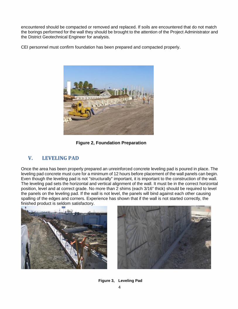
IV. FOUNDATION PREPARATION
MSE walls, like any other structure, need a good foundation to build upon. Proper preparation of the site increases the potential for proper performance of the wall. The foundation for the structure shall be graded level for a width equal to or exceeding the length of soil reinforcement or as shown in the plans. Prior to beginning fill placement, the area under the MSE wall footprint (the zone of the wall facing, soil reinforcement and MSE wall select backfill) should be prepared and compacted with a minimum of five passes with an appropriate vibratory roller weighing at least 8 Tons. Any soft or loose material that is
4
encountered should be compacted or removed and replaced. If soils are encountered that do not match the borings performed for the wall they should be brought to the attention of the Project Administrator and the District Geotechnical Engineer for analysis.
CEI personnel must confirm foundation has been prepared and compacted properly.
Figure 2, Foundation Preparation
V. LEVELING PAD Once the area has been properly prepared an unreinforced concrete leveling pad is poured in place. The leveling pad concrete must cure for a minimum of 12 hours before placement of the wall panels can begin. Even though the leveling pad is not "structurally" important, it is important to the construction of the wall. The leveling pad sets the horizontal and vertical alignment of the wall. It must be in the correct horizontal position, level and at correct grade. No more than 2 shims (each 3/16" thick) should be required to level the panels on the leveling pad. If the wall is not level, the panels will bind against each other causing spalling of the edges and corners. Experience has shown that if the wall is not started correctly, the finished product is seldom satisfactory.
Figure 3, Leveling Pad

5
Figure 4, Improper Leveling Pad
CEI personnel must ensure that a leveling pad has been properly constructed and cured are in accordance with the Contract documents.
VI. PANELS AND PANEL PLACEMENT
WALL FACING PANELS …
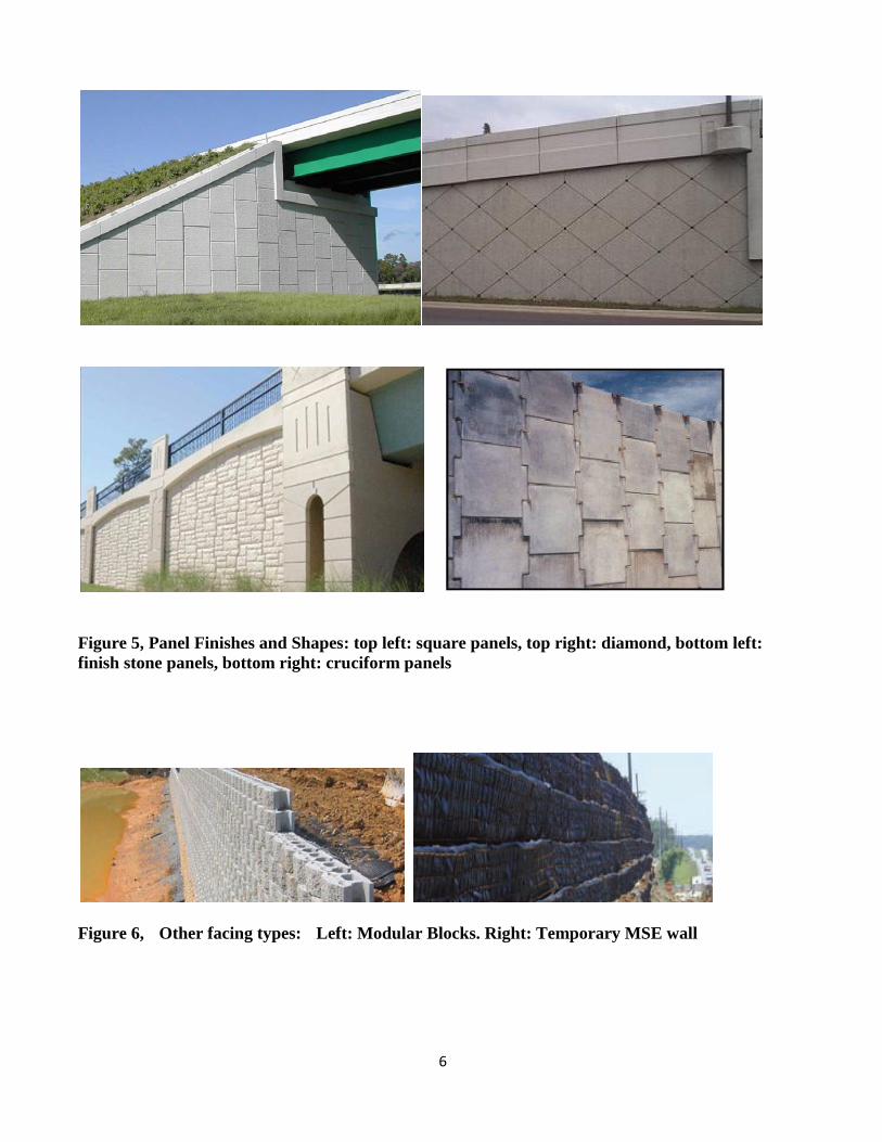
Wall panels come in many shapes and sizes (see Figures 5 and 6 for a few of the most common shapes). They can be custom built into any configuration that will fit together. The front face can have any type of finish, shape, texture or other surface treatments that can be formed. Before the panels are placed, the wall and shop drawings must be checked to ensure that the proper panels are being used. Depending on the wall height, the number of reinforcement connections on the back of the panel may vary. The panels with the most connections will be typically the lower panels of the wall. In the upper portions of the wall, the number of connections may be less. It is important that the panels are used in their proper position. The panels need to be inspected to ensure they meet the plans, specifications, and shop drawings. They also need to be inspected for damage (bent connectors, damaged panels, etc.). The inspector must notify the Project Administrator of any damaged components observed.
6
Figure 5, Panel Finishes and Shapes: top left: square panels, top right: diamond, bottom left:
finish stone panels, bottom right: cruciform panels
Figure 6, Other facing types: Left: Modular Blocks. Right: Temporary MSE wall
7
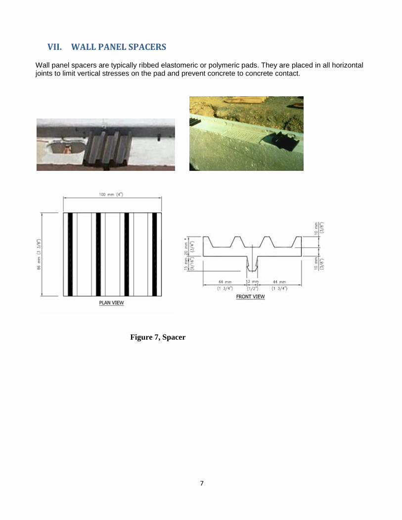
VII. WALL PANEL SPACERS Wall panel spacers are typically ribbed elastomeric or polymeric pads. They are placed in all horizontal joints to limit vertical stresses on the pad and prevent concrete to concrete contact.
Figure 7, Spacer
8
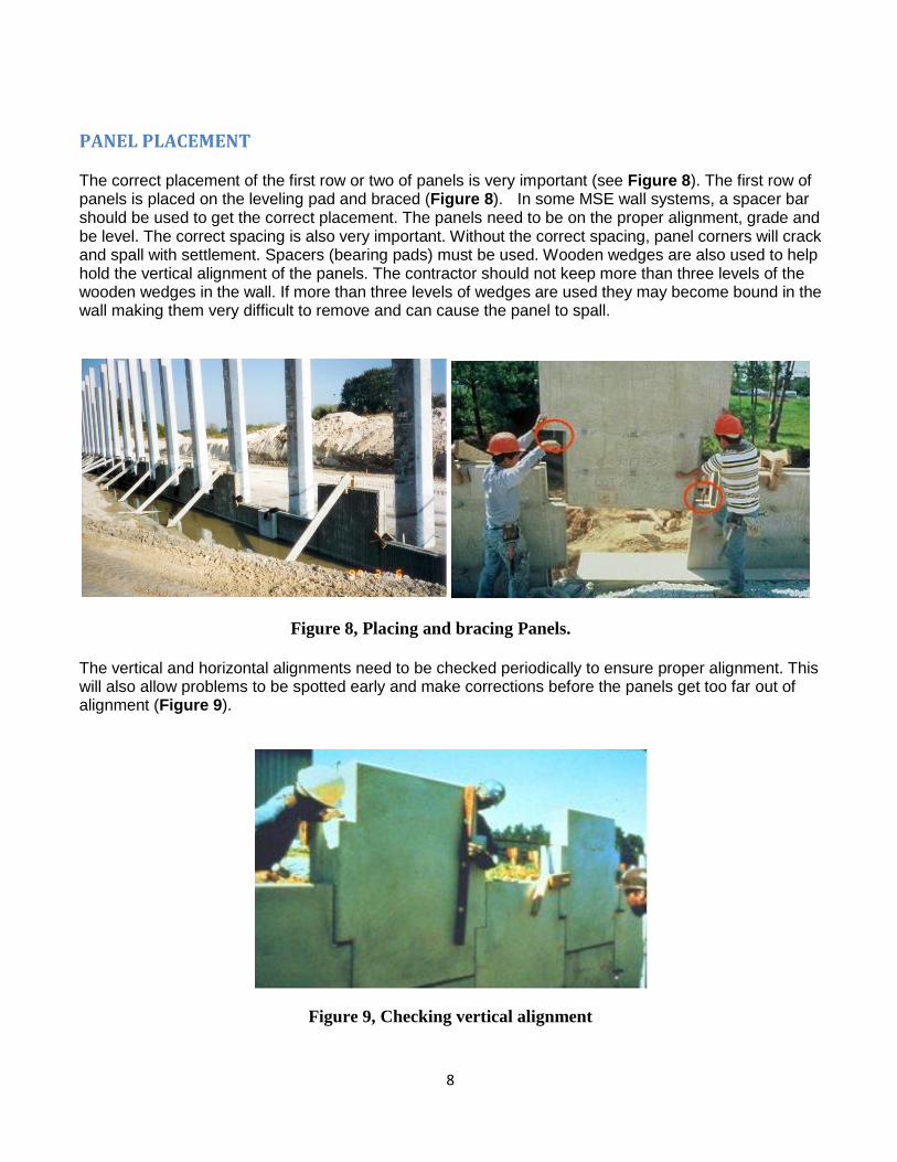
PANEL PLACEMENT The correct placement of the first row or two of panels is very important (see Figure 8). The first row of panels is placed on the leveling pad and braced (Figure 8). In some MSE wall systems, a spacer bar should be used to get the correct placement. The panels need to be on the proper alignment, grade and be level. The correct spacing is also very important. Without the correct spacing, panel corners will crack and spall with settlement. Spacers (bearing pads) must be used. Wooden wedges are also used to help hold the vertical alignment of the panels. The contractor should not keep more than three levels of the wooden wedges in the wall. If more than three levels of wedges are used they may become bound in the wall making them very difficult to remove and can cause the panel to spall.
Figure 8, Placing and bracing Panels.
The vertical and horizontal alignments need to be checked periodically to ensure proper alignment. This will also allow problems to be spotted early and make corrections before the panels get too far out of alignment (Figure 9).
Figure 9, Checking vertical alignment
9
The CEI staff must verify that the batter of the MSE wall panels and the overall MSE wall batter be measured often and at regular intervals. This is important because the vertical alignment of the panels being installed may be affected by the compaction of the soil behind the panels being installed. CEI personnel should measure the overall batter regularly.
SPECIAL PANELS
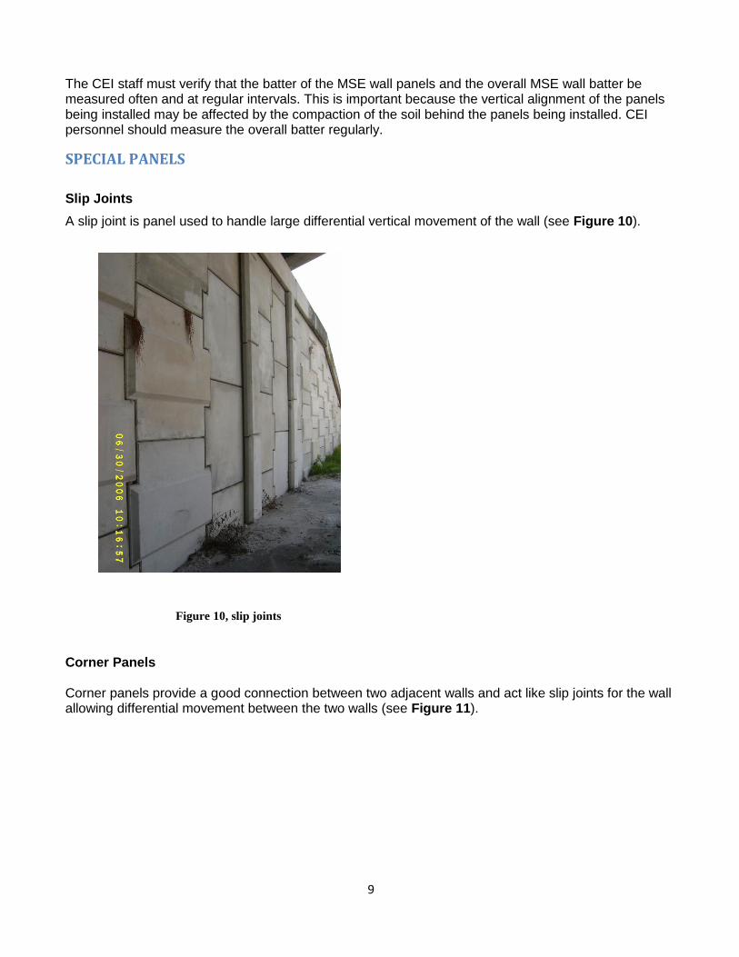
Slip Joints
A slip joint is panel used to handle large differential vertical movement of the wall (see Figure 10).
Figure 10, slip joints
Corner Panels Corner panels provide a good connection between two adjacent walls and act like slip joints for the wall allowing differential movement between the two walls (see Figure 11).

10
Figure 11, Corner Panel
Corner panels shall be used at all corners. If corner panels are not indicated in the shop drawings, the CEI shall contact the wall supplier and Wall Design Engineer immediately.
WOODEN WEDGES
Wooden wedges are used to help hold the panels at the correct batter during the backfill placement. The wooden wedges should be made from hard wood (such as oak, maple or ash)
Figure 12, wooden wedges
Wooden wedges should be removed as soon as the panel above the wedged panel is completely erected and backfilled.
11
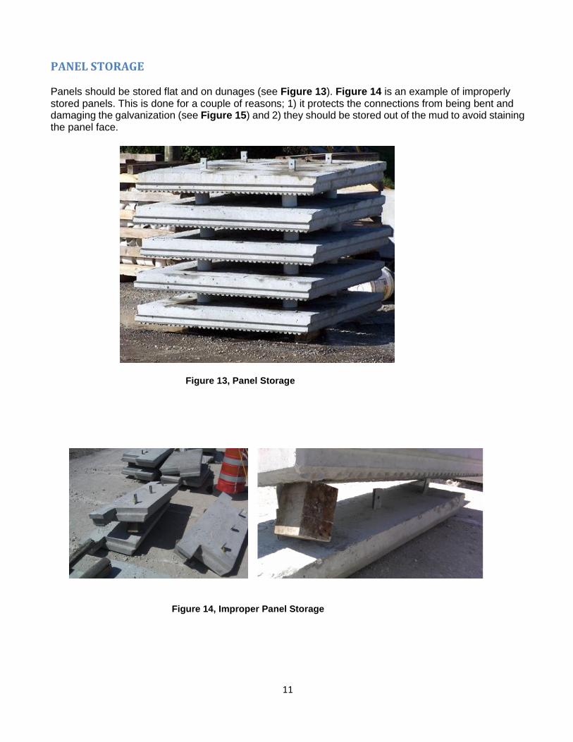
PANEL STORAGE Panels should be stored flat and on dunages (see Figure 13). Figure 14 is an example of improperly stored panels. This is done for a couple of reasons; 1) it protects the connections from being bent and damaging the galvanization (see Figure 15) and 2) they should be stored out of the mud to avoid staining the panel face.
Figure 13, Panel Storage
Figure 14, Improper Panel Storage
12
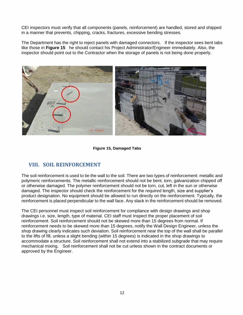
CEI inspectors must verify that all components (panels, reinforcement) are handled, stored and shipped in a manner that prevents, chipping, cracks, fractures, excessive bending stresses. The Department has the right to reject panels with damaged connectors. If the inspector sees bent tabs like those in Figure 15 he should contact his Project Administrator/Engineer immediately. Also, the inspector should point out to the Contractor when the storage of panels is not being done properly.
Figure 15, Damaged Tabs
VIII. SOIL REINFORCEMENT
The soil reinforcement is used to tie the wall to the soil. There are two types of reinforcement: metallic and polymeric reinforcements. The metallic reinforcement should not be bent, torn, galvanization chipped off or otherwise damaged. The polymer reinforcement should not be torn, cut, left in the sun or otherwise damaged. The inspector should check the reinforcement for the required length, size and supplier’s product designation. No equipment should be allowed to run directly on the reinforcement. Typically, the reinforcement is placed perpendicular to the wall face. Any slack in the reinforcement should be removed. The CEI personnel must inspect soil reinforcement for compliance with design drawings and shop drawings i.e. size, length, type of material. CEI staff must Inspect the proper placement of soil reinforcement. Soil reinforcement should not be skewed more than 15 degrees from normal. If reinforcement needs to be skewed more than 15 degrees, notify the Wall Design Engineer, unless the shop drawing clearly indicates such deviation. Soil reinforcement near the top of the wall shall be parallel to the lifts of fill, unless a slight bending (within 15 degrees) is indicated in the shop drawings to accommodate a structure. Soil reinforcement shall not extend into a stabilized subgrade that may require mechanical mixing. Soil reinforcement shall not be cut unless shown in the contract documents or approved by the Engineer.

13
METALLIC REINFORCEMENT (INEXTENSIBLE)
It is the mostly used in permanent MSE wall applications for the Department. Its use is limited when the environmental conditions are highly corrosive. They are made of galvanized steel. The most common are ribbed strips and metallic grid indicated in Figure 17) .
Figure 16, Soil Reinforcement
Figure 17 , Metallic Reinforcement (Inextensible). Left: metallic grid. Right: Ribbed Strips.
POLYMERIC (Geosynthetics)-EXTENSIBLE REINFORCEMENT Geosynthetic reinforcement could be geogrids or geotextiles. They are typically used in temporary walls as well as in permanent walls in corrosive environments and in modular block (segmental) walls. The polymeric reinforcement should have some tension placed in the reinforcement during fill placement to remove slack. The reinforcement should not be connected to the wall until the compacted fill is at or
14
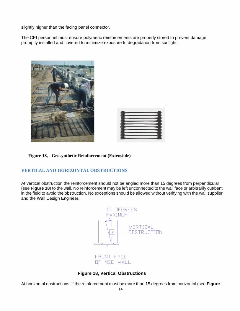
slightly higher than the facing panel connector.
The CEI personnel must ensure polymeric reinforcements are properly stored to prevent damage, promptly installed and covered to minimize exposure to degradation from sunlight.
Figure 18, Geosynthetic Reinforcement (Extensible)
VERTICAL AND HORIZONTAL OBSTRUCTIONS
At vertical obstruction the reinforcement should not be angled more than 15 degrees from perpendicular (see Figure 18) to the wall. No reinforcement may be left unconnected to the wall face or arbitrarily cut/bent in the field to avoid the obstruction. No exceptions should be allowed without verifying with the wall supplier
and the Wall Design Engineer.
Figure 18, Vertical Obstructions
At horizontal obstructions, if the reinforcement must be more than 15 degrees from horizontal (see Figure

15
19) the Wall Design Engineer must be contacted. It may need additional reinforcement length to meet design requirements. Also when clearing horizontal obstructions, the reinforcement should be smoothly curved around the obstruction. The reinforcement should not be kinked at any time. There should also be a minimum of 4 inches of cover between the obstruction and the reinforcement. Table 1 shows the recommended transition distance X (see "X" in Figure 20) from the point of connection to provide a smooth curve of the reinforcement with an offset of d (see "d" in Figure 20). If these distances cannot be achieved the wall supplier should be contacted to check the design.
Figure 19, Horizontal Obstructions
Figure 20, Transition Distances for horizontal obstructions
Table 1. Transition Distances
The CEI staff must verify the soil reinforcement straps are not cut and that the 15 degrees skew angle is not exceeded. The CEI staff must ensure that the Contractor submit shop drawings approved by the Wall Design Engineer detailing any cutting of soil reinforcement. No cutting in the reinforcement may be allowed until these shop drawings are submitted and approved. The CEI must also ensure that the Contractor submit shop drawings approved by the Wall Design Engineer which detail construction of the

16
wall around obstructions including details addressing conflicts between the soil reinforcement and any obstructions within the wall volume. The CEI must contact the Wall Design Engineer immediately if cutting of reinforcement, excessive transition angles or details around obstructions are not properly addressed in the shop drawings.
REINFORCEMENT STORAGE Like the panels the reinforcement should be stored on dunage (see Figure 21) and carefully handled to prevent damage. Damage may include bending of the reinforcement and damaging the galvanization.
Figure 21, Reinforcement Storage
WALL/REINFORCEMENT CONNECTION Connection devices are incorporated into the panels to attach the soil reinforcement. In tab connection devices the nut should be placed on top (with the head of the bolt underneath) to make sure it is going to be placed and tightened.
Figure 22, Reinforcement Connections
17
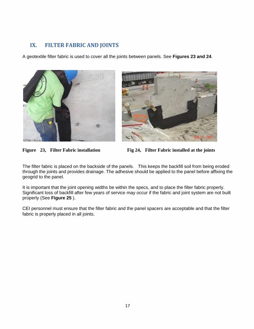
IX. FILTER FABRIC AND JOINTS A geotextile filter fabric is used to cover all the joints between panels. See Figures 23 and 24.
Figure 23, Filter Fabric installation Fig 24, Filter Fabric installed at the joints
The filter fabric is placed on the backside of the panels. This keeps the backfill soil from being eroded through the joints and provides drainage. The adhesive should be applied to the panel before affixing the geogrid to the panel. It is important that the joint opening widths be within the specs, and to place the filter fabric properly. Significant loss of backfill after few years of service may occur if the fabric and joint system are not built properly (See Figure 25 ). CEI personnel must ensure that the filter fabric and the panel spacers are acceptable and that the filter
fabric is properly placed in all joints.

18
Figure 25, Loss of backfill through improperly constructed joint and filter fabric (Left: backfill washed through joint deposited next to the slip panel. Right: Void as observed from the top of wall)
X. COPING/BARRIER Coping is used to tie in the top of the wall panels and to provide a smooth pleasing finish to the wall top. Coping/barriers can be cast-in-place or prefabricated segments. For precast units a leveling course of concrete is placed prior to setting the units in place (see Figure 28). This provides the vertical control needed. Barriers are tied together and strengthened against vehicle impact by a junction (moment) slab (see Figures 27 and 28).
Figure 26 , coping

19
Figure 27, Barrier with Slab. Cast-in-place
Figure 28, Precast Barrier. Indicated in red is the leveling concrete.
When precast coping is used, CEI personnel must verify that top panels have dowels that will extend into the cast-in-place Buildup concrete (refer to the wall coping Design Standard indices). When cast-in-place coping is used CEI personnel must verify that a one-half inch minimum preformed expansion material between wall panels and cast-in-place concrete is placed (refer to the wall coping Design Standard indices)
XI. ABUTMENT CHEEK WALLS When abutments are on a deep foundation, a bond breaker is needed between the MSE Wall panel and the cheek wall (see Figure 29). If this is not done, when the wall settles and the abutment doesn‘t, it creates a tension load in the cheek wall and the panel. This eventually leads to one or both to crack (see Figure 30 and Figure 31). When rough panel finishes are used (such as shown Figure 30) a heavy/thick bond breaker is required. In cases such as this a thin paper bond breaker forms to the panel irregularities and the panel locks into the poured concrete. With smooth panel finishes a paper bond breaker would

20
usually be sufficient.
Figure 29, Bond Breaker
Figure 30, Cracked Panel and Cheek Wall Figure 31, Tension Break in Cheek Wall
XII. SELECT MSE WALL BACKFILL The select backfill must meet the specification requirements for gradation, electro-chemical, soil plasticity properties and organic content. It must be free drainage materials, having therefore a limited amount of fines (material passing sieve #200). Please check the specs, section 548 for the current gradation limits and the maximum amount of fines permissible. Typical materials acceptable will fall within the AASHTO classification of A-1, A-3 and A-2-4 (towards the lower end of percentage passing #200 sieve; close to the A-3 classification). In special cases, the plans and/or shop drawings may require higher soil friction angles to meet stability requirements. In these cases the Contractor is required to perform direct shear tests to proof that the material supplied meets the design requirements. As a minimum the Contractor needs to supply three (3) direct shear tests (performed in accordance with AASTHO T-236) per soil type. The lowest soil friction angle obtained from the three direct shear tests must be equal or exceed the value indicated in the
21
plans/shop drawings. These special testing will be required in the following cases:
For A-3 and A-2-4 materials: When the assumed or required design soil friction angle is greater than 30o.
For limerock material (which may be used in some projects in South Florida): When the assumed or required design soil friction angle is greater than 34o.
PLACING BACKFILL
The select backfill lift should be placed parallel to the wall and starting approximately three (3) feet from the back of the wall panels. The backfill should be placed in 6" compacted lifts (it may be helpful to mark your lifts on the back side of the wall panels). The fill is then leveled by machinery moving parallel to the wall, windrowing the material toward the reinforcement ends. This action works out any slack in the reinforcement then locking the reinforcement and the panels in position. Once this has been accomplished, fill is then placed within 3‘ behind the wall by windrowing the material except for the initial layer, for which the fill must be brought up uniformly for the whole layer.
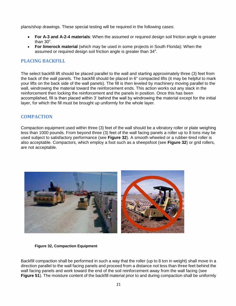
COMPACTION Compaction equipment used within three (3) feet of the wall should be a vibratory roller or plate weighing less than 1000 pounds. From beyond three (3) feet of the wall facing panels a roller up to 8 tons may be used subject to satisfactory performance (see Figure 32). A smooth wheeled or a rubber-tired roller is also acceptable. Compactors, which employ a foot such as a sheepsfoot (see Figure 32) or grid rollers, are not acceptable.
Figure 32, Compaction Equipment
Backfill compaction shall be performed in such a way that the roller (up to 8 ton in weight) shall move in a direction parallel to the wall facing panels and proceed from a distance not less than three feet behind the wall facing panels and work toward the end of the soil reinforcement away from the wall facing (see Figure 51). The moisture content of the backfill material prior to and during compaction shall be uniformly
22
distributed throughout each layer of material. Backfill material shall have placement moisture content on the dry side of the Optimum Moisture content. If additional water is required for the material, the water must meet the specification requirements.
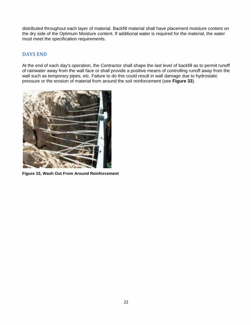
DAYS END At the end of each day's operation, the Contractor shall shape the last level of backfill as to permit runoff of rainwater away from the wall face or shall provide a positive means of controlling runoff away from the wall such as temporary pipes, etc. Failure to do this could result in wall damage due to hydrostatic pressure or the erosion of material from around the soil reinforcement (see Figure 33).
Figure 33, Wash Out From Around Reinforcement

23
BACKFILL IN FRONT OF WALL
The area in front of the wall and around the leveling pad should be backfilled as soon as practically possible. A strong rainstorm could cause heavy flow along the wall. This could cause soil erosion and undermining of the leveling pad and the wall (Figure 34).
Figure 34, Undermining of leveling pad
XIII. MISCELLANEOUS POINTS
CONSTRUCTION LOADS Before the actual start of construction of the wall, the various parts of the plans (shop drawings, drainage, lighting, etc.) need to be compared to the contract wall plans to check for conflicts. A conflict may not have been noticed in the design stage. If the plans show heavy loads on the wall and the shop drawings do not indicate it,the wall supplier should be questioned. The wall supplier may not have seen a full set of plans. Due to this, he may have missed loadings from various types of structures. If he did not take these loads into consideration, the wall could fail. This also can be temporary loads that the contractor may impose that was not accounted for (see Figure 35)
24
Figure 35, Construction Load
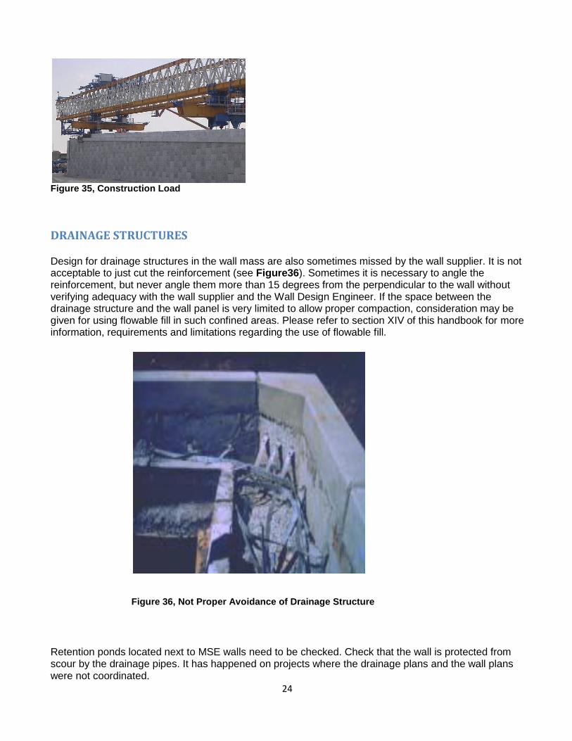
DRAINAGE STRUCTURES Design for drainage structures in the wall mass are also sometimes missed by the wall supplier. It is not acceptable to just cut the reinforcement (see Figure36). Sometimes it is necessary to angle the reinforcement, but never angle them more than 15 degrees from the perpendicular to the wall without verifying adequacy with the wall supplier and the Wall Design Engineer. If the space between the drainage structure and the wall panel is very limited to allow proper compaction, consideration may be given for using flowable fill in such confined areas. Please refer to section XIV of this handbook for more information, requirements and limitations regarding the use of flowable fill.
Figure 36, Not Proper Avoidance of Drainage Structure
Retention ponds located next to MSE walls need to be checked. Check that the wall is protected from scour by the drainage pipes. It has happened on projects where the drainage plans and the wall plans were not coordinated.
25
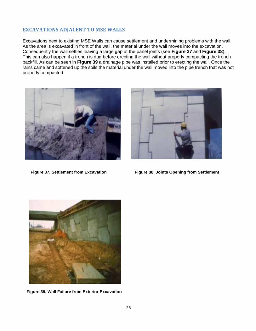
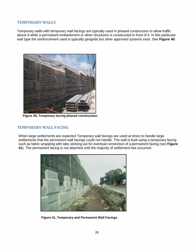
EXCAVATIONS ADJACENT TO MSE WALLS Excavations next to existing MSE Walls can cause settlement and undermining problems with the wall. As the area is excavated in front of the wall, the material under the wall moves into the excavation. Consequently the wall settles leaving a large gap at the panel joints (see Figure 37 and Figure 38). This can also happen if a trench is dug before erecting the wall without properly compacting the trench backfill. As can be seen in Figure 39 a drainage pipe was installed prior to erecting the wall. Once the rains came and softened up the soils the material under the wall moved into the pipe trench that was not properly compacted.
Figure 37, Settlement from Excavation Figure 38, Joints Opening from Settlement
. Figure 39, Wall Failure from Exterior Excavation
26
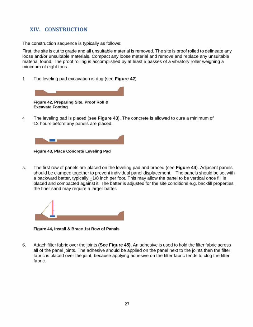
TEMPORARY WALLS Temporary walls with temporary wall facings are typically used in phased construction to allow traffic above it while a permanent embankment or other structures is constructed in front of it. In this particular
wall type the reinforcement used is typically geogrids but other approved systems exist. See Figure 40. .
Figure 40, Temporary during phased construction
TEMPORARY WALL FACING
When large settlements are expected Temporary wall facings are used at times to handle large settlements that the permanent wall facings could not handle. The wall is built using a temporary facing such as fabric wrapping with tabs sticking out for eventual connection of a permanent facing (see Figure 41). The permanent facing is not attached until the majority of settlement has occurred.
Figure 41, Temporary and Permanent Wall Facings
27
XIV. CONSTRUCTION
The construction sequence is typically as follows:
First, the site is cut to grade and all unsuitable material is removed. The site is proof rolled to delineate any loose and/or unsuitable materials. Compact any loose material and remove and replace any unsuitable material found. The proof rolling is accomplished by at least 5 passes of a vibratory roller weighing a minimum of eight tons.
1 The leveling pad excavation is dug (see Figure 42)
Figure 42, Preparing Site, Proof Roll & Excavate Footing
4 The leveling pad is placed (see Figure 43). The concrete is allowed to cure a minimum of
12 hours before any panels are placed.
Figure 43, Place Concrete Leveling Pad
5. The first row of panels are placed on the leveling pad and braced (see Figure 44). Adjacent panels
should be clamped together to prevent individual panel displacement. The panels should be set with a backward batter, typically +1/8 inch per foot. This may allow the panel to be vertical once fill is placed and compacted against it. The batter is adjusted for the site conditions e.g. backfill properties, the finer sand may require a larger batter.
Figure 44, Install & Brace 1st Row of Panals
6. Attach filter fabric over the joints (See Figure 45). An adhesive is used to hold the filter fabric across
all of the panel joints. The adhesive should be applied on the panel next to the joints then the filter fabric is placed over the joint, because applying adhesive on the filter fabric tends to clog the filter fabric.

28
Figure 45, Attach Filter Fabric
7. The select backfill is then placed and compacted to the level of the first row of connections. The compacted fill should be at or slightly higher than the panel connections (see Figure 45). On the initial row of panels (and only the initial row of panels) the backfill is not placed against the panel until the first row of reinforcement has been connected and the initial 6 inch layer of compacted fill is placed on the reinforcement. This is to keep the bottom of the panels from "kicking out". From that point, the backfill is brought up uniformly from the back of the panels to the end of the reinforcement.
Figure 46, Fill in 6” Lifts to Reinforcement Figure 47, Connect and Tighten Reinforcement
8. The reinforcement is then placed typically perpendicular to the wall panel and the connection (see Figure 47). Any slack in the reinforcement should be removed to avoid excessive panel movement. With polymeric reinforcement some tension should be applied to the reinforcement by means of a kicker tension device or a rod (see Figure 48).
Figure 48, Tightening polymer Reinforcement

29
9. Then another row of wall panels is placed with the proper batter.
10. The select backfill is then placed (see Figure 49) in 6 inch compacted lifts until the fill is at or
slightly above the next set of connections. Any additional water needed for compaction must meet the specification requirements. The backfill is placed parallel to the wall starting approximately three (3) feet from the back of the panels. The fill is then windrowed toward the reinforcement ends (see Figure 50). Once this is complete, the fill is windrowed from the three (3) foot point back toward the panels (see Figure 51).
Figure 49, Typical Edge Fill Placement Figure 50, Typical Edge Fill Placement (Plan View) (Plan View)
11. The compaction equipment rolls parallel to the wall facing. Compaction starts at least three (3) feet from the wall and works toward the end of the reinforcement (see Figure 51).
Figure 51, Initial Compaction Figure 52, Final Compaction
30
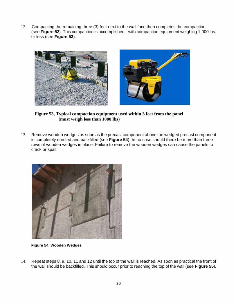
12. Compacting the remaining three (3) feet next to the wall face then completes the compaction (see Figure 52). This compaction is accomplished with compaction equipment weighing 1,000 lbs. or less (see Figure 53).
Figure 53, Typical compaction equipment used within 3 feet from the panel
(must weigh less than 1000 lbs)
13. Remove wooden wedges as soon as the precast component above the wedged precast component is completely erected and backfilled (see Figure 54). In no case should there be more than three rows of wooden wedges in place. Failure to remove the wooden wedges can cause the panels to crack or spall.
Figure 54, Wooden Wedges
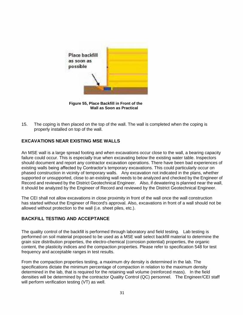
14. Repeat steps 8, 9, 10, 11 and 12 until the top of the wall is reached. As soon as practical the front of
the wall should be backfilled. This should occur prior to reaching the top of the wall (see Figure 55).
31
Figure 55, Place Backfill in Front of the Wall as Soon as Practical
15. The coping is then placed on the top of the wall. The wall is completed when the coping is properly installed on top of the wall.
EXCAVATIONS NEAR EXISTING MSE WALLS
An MSE wall is a large spread footing and when excavations occur close to the wall, a bearing capacity failure could occur. This is especially true when excavating below the existing water table. Inspectors should document and report any contractor excavation operations. There have been bad experiences of existing walls being affected by Contractor’s temporary excavations. This could particularly occur on phased construction in vicinity of temporary walls. Any excavation not indicated in the plans, whether supported or unsupported, close to an existing wall needs to be analyzed and checked by the Engineer of Record and reviewed by the District Geotechnical Engineer. Also, if dewatering is planned near the wall, it should be analyzed by the Engineer of Record and reviewed by the District Geotechnical Engineer. The CEI shall not allow excavations in close proximity in front of the wall once the wall construction has started without the Engineer of Record's approval. Also, excavations in front of a wall should not be allowed without protection to the wall (i.e. sheet piles, etc.).
BACKFILL TESTING AND ACCEPTANCE
The quality control of the backfill is performed through laboratory and field testing. Lab testing is performed on soil material proposed to be used as a MSE wall select backfill material to determine the grain size distribution properties, the electro-chemical (corrosion potential) properties, the organic content, the plasticity indices and the compaction properties. Please refer to specification 548 for test frequency and acceptable ranges in test results. From the compaction properties testing, a maximum dry density is determined in the lab. The specifications dictate the minimum percentage of compaction in relation to the maximum density determined in the lab, that is required for the retaining wall volume (reinforced mass). In the field densities will be determined by the contractor Quality Control (QC) personnel. The Engineer/CEI staff will perform verification testing (VT) as well.
32
FIELD DENSITY REQUIREMENTS
The CEI staff must verify that the backfill is placed and compacted in accordance with plans and specifications and that the Earth Density books are properly prepared. Check that water used for soil compaction is in compliance with section 923 (No salt or brackish water). Do not allow thick lift compaction as lifts thicker than 6" (150 mm) require more energy to compact and may move the panels out of alignment. [Spec. 548-6] The MSE wall backfill shall have the following minimum dry densities:
The material beyond 3 ft from the back of the panels shall have a minimum dry density of 95% of the maximum density determined in the Modified Proctor test, in accordance with the FM 1-T 180 procedure.
The material within 3 ft from the back of the panels shall have a minimum dry density of 90% of the maximum density determined in the Modified Proctor test, in accordance with the FM 1-T 180 procedure.
If the Material classifies as A-2-4 or A-3 at the Contractor’s option, the MSE wall backfill may be compacted to the following alternative criteria:
Material beyond 3 ft from the back of the panels: minimum dry density of 100% of the maximum density determined in the Standard Proctor test, in accordance with the AASHTO T-99 method C procedure.
The material within 3 ft from the back of the panels shall have a minimum dry density of 95% of the maximum density determined in the Standard Proctor test, in accordance with the FM 1-T 99 method C procedure.
In the 3 ft zone within the back of the panels the compactor equipment weight cannot exceed 1000 lbs. The reason to limit the weight of the equipment and a lower density requirement in this zone is to minimize movement of the panels. Note: For pipe backfill within the MSE wall reinforcement volume, the compaction requirements for the MSE wall backfill describe above will apply. LOTS A LOT is defined typically as a single lift of finished backfill not to exceed 500 ft in length. The maximum thickness of compacted material allowed by the specifications in a lift is 6 inches. The contractor is required to perform at least 1 QC field density test per LOT. The Department will perform 1 VT field density test every 4 LOTs. Since the material within 3 feet from the wall has a different compaction requirement (less) than the rest of the reinforced volume and the equipment is different, there will be two LOTS in any given 500 ft of wall: One for the MSE wall select backfill within 3 ft from the wall and another for the MSE walls select backfill material beyond 3 ft from the panels. See Figure 56. Therefore in any given 500 ft length of wall of Figure 56, the Contractor QC inspector is to perform 1 field density test for every lift in the zone within 3 ft of the panels, and 1 field density test for every lift in the zone beyond the 3 ft from the panels.

33
Figure 56. In this case, in every 500 ft, there are two LOTS for the MSE wall backfill in addition to the LOT for the embankment, per lift.
In the case of parallel walls where the reinforcement overlaps, only one LOT is necessary, if the two adjacent areas are compacted in the same operation, following the same procedures and using the same
backfill material. See Figure 57.
Figure 57. Parallel walls, overlapping reinforcement
In the case of Figure 57, for every 500 ft of length, if the same material and same procedures are used, then for every 500 ft, 3 density tests will be required per lift: 2 for the two separate areas within 3 ft from the panels and 1 for the middle area.
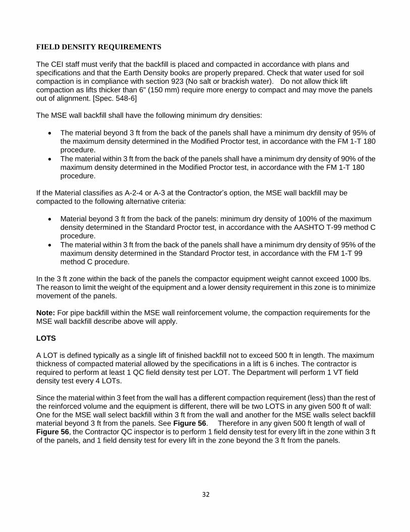
If there is a gap between reinforcements, and this gap is not greater than 8 ft, and it is built with the same material, and compacted in the same manner, the two adjacent MSE wall backfills (excluding the 3 ft
within the panels) and the gap may be considered as one LOT. (Figure 58)
34
Figure 58 . Paralell walls, with a narrow gap between reinforcements
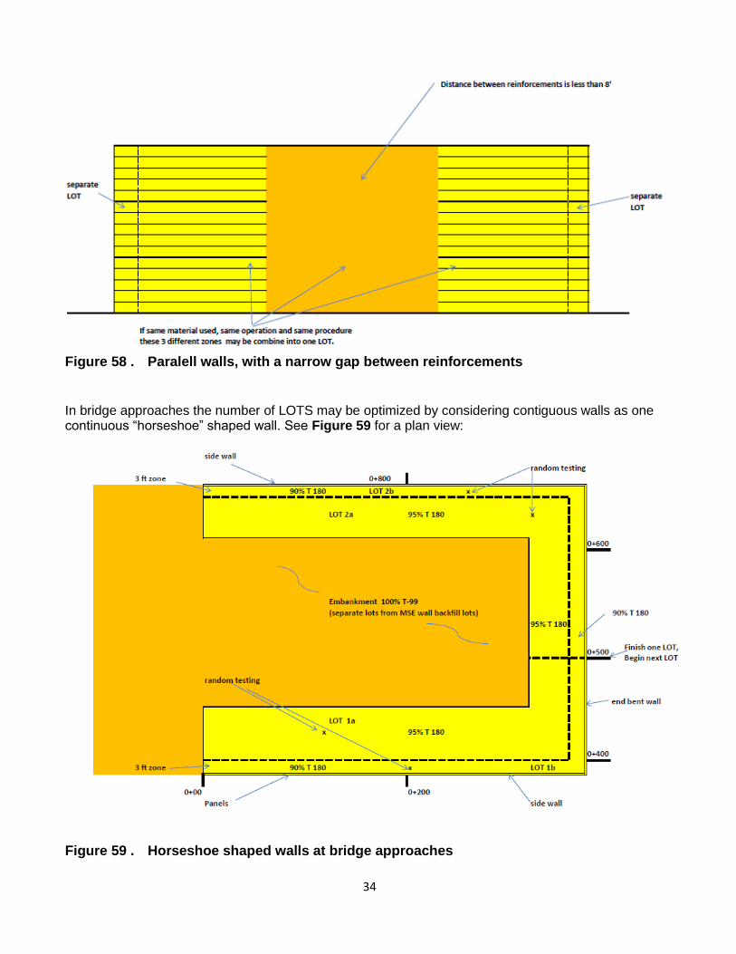
In bridge approaches the number of LOTS may be optimized by considering contiguous walls as one continuous “horseshoe” shaped wall. See Figure 59 for a plan view:
Figure 59 . Horseshoe shaped walls at bridge approaches

35
FLOWABLE FILL The FDOT specifications allow the use of flowable fill as MSE wall backfill material when it is specified in the plans. Flowable fill is a mixture of Portland cement, fly ash, fine aggregate, admixture and water. Flowable fill contains a low cementitious content for reduced strength development. When flowable fill is used the metallic wall components (including metallic soil reinforcements) must not be in partial contact with the flowable fill. If the metallic components contact the flowable fill, the metallic components must be completely encapsulated by the flowable fill. Metallic elements partially embedded in cementitious materials have been found to be susceptible to corrosion. A type of low density flowable fill called cellular concrete is also allowed by the specifications. A cellular flowable fill is a low density concrete made with cement, water and preformed foam to form a hardened closed cell foam material. Cellular concrete flowable fill may also contain fine aggregate, fly ash, slag and admixtures. The use of cellular concrete may be very convenient when there is a need for relatively narrow widenings in front of an existing retaining wall. Figure 60 illustrates a wall constructed with full height panels (known as tilt panels) using cellular concrete as backfill next to an existing cantilever concrete retaining wall.
Figure 60, Cellular Concrete Wall

36
APPENDIX A CHECK LIST The following is a general checklist to follow when constructing a Mechanically Stabilized Earth wall (MSE
wall). The answer to each of these should be yes unless plans, specifications or specific approval has been given
otherwise.
YES NO
1. □ □ Has the contractor submitted wall shop drawings?
2. □ □ Has the contractor submitted signed and sealed select backfill certification (showing that it meets the gradation, density and corrosion and other soil requirements)?
3. □ □ Has the contractor supplied a Certificate of Compliance certifying that the wall
materials comply with the applicable sections of the specifications? Has the contractor supplied a copy of all test results performed by the Contractor or his supplier, which are necessary to assure compliance with the specifications?
4. □ □ Has the contractor furnished a copy of any instructions the wall supplier may have furnished?
5. □ □ Have the shop drawings been approved?
6. □ □ Did the contractor receive the correct panels (shape, size and soil reinforcement
connection layout) per the approved shop drawings?
7. □ □ Did the contractor receive the correct reinforcement (proper length, size, and proper product designation)?
8. □ □ Have the panels and the reinforcement been inspected for damage as outlined in the specifications?
9. □ □ If any panels or soil reinforcement were found damaged have they been rejected or repaired in accordance with the specifications?
10. □ □ Are the panels and the soil reinforcement properly stored to prevent damage?
11. □ □ Has the MSE wall area been excavated to the proper elevation?
12. □ □ Has the area been proof rolled per the specifications (a minimum of five (5)
passes by a roller weighing a minimum of 8 tons)? 13. □ □ Has all soft or unsuitable materials been compacted or removed and replaced? 14. □ □ If the contractor is using any water in the MSE wall area does it meet the
requirements shown in the specifications?
15. □ □ Has the leveling pad area been properly excavated?
16. □ □ Has the leveling pad been set to the proper vertical and horizontal alignment?
17. □ □ Has the leveling pad cured for a minimum of 12 hours before any panels are
set?

37
YES NO
18. □ □ Is the first row of panels properly placed? Do they have proper spacing, bracing,
tilt and where required, do they have the spacers installed?
19. □ □ Has the proper filter fabric and adhesive been supplied?
20. □ □ Is the filter fabric being properly placed over all the panel joints?
21. □ □ Is the adhesive being applied to the panel, and then the filter fabric being
placed?
22. □ □ Is the filter fabric being stored properly (stored out of the sunlight and protected from UV radiation)?
23. □ □ Is the contractor using the correct panels (correct size, shape and with the proper number of connections) for that panel's wall location and elevation?
24. □ □ Is the fill being placed and compacted in 6 inch thick lifts?
25. □ □ Is the equipment being kept off of the soil reinforcement until a minimum of 6
inches of fill is placed?
26. □ □ Are the lifts being placed by the proper method and sequence
27. □ □ Is the fill being compacted by the correct equipment and in the correct pattern?
28. □ □ Are the proper compaction requirements being met? Are the minimum percentage compaction
achieved within 3 feet from the panels and beyond three feet from the panels?
28. □ □ Are separate densities (separate LOTs) being taken for the 3 ft from the
panels and beyond 3 ft from the panels ?
29. □ □ Is the fill being brought up to or slightly above the soil reinforcement elevation
before the reinforcement are connected? 30. □ □ Is the soil reinforcement being properly connected (connections tight and all of
the slack in the soil reinforcement removed)? 31. □ □ Are the soil reinforcements in the proper alignment? 32. □ □ Is the vertical and horizontal alignment being checked periodically and adjusted
as needed?
33. □ □ Are the correct reinforced length and sizes installed per shop drawings 34. □ □ Are the constructed panel joints being checked periodically to verify the specification limits
are met?
35. □ □ Is the contractor removing the wooden wedges as per the specifications? (The wooden wedges shall be removed as soon as the panel above the wedged panel is completely erected and backfilled.)

38
YES NO
36. □ □ At the end of each day's operation is the contractor shaping the last level of backfill as to
permit runoff of rainwater away from the wall face or providing a positive means of controlling runoff away from the wall such as temporary pipe, etc?
37. □ □ Has the contractor backfilled the front of the wall?
38. □ □ Is the correct coping being installed?

B-1
APPENDIX B
MSE WALL CONSTRUCTION DO'S AND DON'TS 1. Review approved shop drawings.
2. Review Mechanically Stabilized Earth (MSE) Wall Inspector's Handbook.
3. Confirm foundation has been compacted properly in accordance to the specifications.
4. Verify leveling pad elevations.
5. Confirm receipt of Certificate of Compliance from the wall company.
6. Confirm receipt of signed and sealed of proposed select backfill fill materials. Confirm backfill materials
have been tested and approved before it is brought to the job site.
7. Inspect panels.
8. Inspect soil reinforcement for damage.
9. Reject all panels that are not in compliance with the plans and specifications.
10. Ensure panels, soil reinforcement and filter fabrics are properly stored to prevent damage.
11. Ensure all piles in the reinforced fill are wrapped with two independent layers of 6 mil plastic with
lubricating oil between the layers.
12. Install panels in accordance to shop drawings, plans and specifications.
13. Place and properly compact fill in accordance with plans and specifications.
14. DO NOT use thick fill lifts. Fill lifts thicker than 6" compacted lifts require more energy to compact and
may move the panels out of alignment.
15. Use corner panels at all corners. If corner panels are not indicated on the plans, the wall supplier and the
Wall Design Engineer should be notified.
16. Verify installed reinforcement lengths behind panel.
17. Soil reinforcement should not be skewed more than 15 degrees from normal. If reinforcement needs to be
skewed more than 15 degrees, notify the wall supplier and the Wall Design Engineer.
18. Check the batter of the panels often. Adjust accordingly. The vertical alignment of the panels below the
panels being installed may be affected by the compaction of the soil behind the panels being installed.
19. Check overall batter regularly.
20. Water for soil compaction shall be in compliance with Section 923. NO saltwater or brackish water is to
be used.
21. When attaching filter fabric to the back of the panels, the adhesive shall be applied to the panel NOT the
filter fabric.
22. Remove wooden wedges as soon as possible.
23. If precast coping is used, ensure top panels have dowels that will extend into the cast-in-place Buildup
concrete.
24. DO NOT allow excavations in close proximity in front of the wall once the wall construction has started.
If excavations are required in front of the wall, the Engineer of Record's approval will be obtained before
the excavation is started. Also, excavations in front of the wall should not be allowed without protection
to the wall (i.e. sheet piles, etc.)
25. Soil reinforcement near the top of the wall shall be parallel to the lifts of fill. Soil reinforcement shall not
extend into the stabilized subgrade that may require mechanical mixing.
26. DO NOT CUT soil reinforcement to avoid obstructions without the approval of the Wall Design Engineer.
27. Place one-half inch minimum preformed expansion material between wall panels and cast-in-place
concrete

C-1
APPENDIX C OUT-OF-TOLERANCE CONDITIONS AND POSSIBLE CAUSES CRITERIA
The following is taken out of FHWA‘s Publication —DESIGN AND CONSTRUCTION OF
MECHANICALLY STABILIZED EARTH WALLS AND REINFORCED SOIL SLOPES- Publication No.
FHWA-NHII-10-025, November 2009.
Table 11.4. Out-of-Tolerance Conditions and Possible Causes
MSE structures are to be erected in strict compliance with the structural and aesthetic requirements of the plans,
specifications, and contract documents. The desired results can generally be achieved through the use of quality
materials, correct construction/erection procedures, and proper inspection. However, there may be occasions
when dimensional tolerances and/or aesthetic limits are exceeded. Corrective measures should quickly be taken
to bring the work within acceptable limits. Presented below are several out-of-tolerance conditions and their
possible causes.
CONDITION POSSIBLE CAUSE
1. Distress in wall:
a. Differential settlement or low spot in
wall (Cause 1a & b apply)
b. Overall wall leaning beyond vertical
alignment tolerance (Cause 1 a & b).
c. Spalling, chipping, or cracking of
facing units (Cause 1 a – e apply) (e.g.,
from panel to panel contact or
differential movement of modular
block facing units).
.
2. First panel course difficult
(impossible) to set and/or maintain level..
3. Wall out of vertical alignment
tolerance (plumbness), or leaning out.
1.a. Foundation (subgrade) material too
soft or wet for proper bearing.
.b . Fill material of poor quality or not
properly compacted..
c. Inadequate spacing in horizontal
and vertical joints.
d. Use of improper bearing pads
e. Stones or concrete pieces between
facing units (e.g. units not clean
or used to face units)
2.a. Leveling pad not level
3.a. Panel not battered sufficiently.
b. Oversized compaction equipment
working within 3 foot zone of
back of wall facing panels.
c. Backfill material placed wet of
optimum moisture content.
Backfill contains excessive fine

C-2
4. Wall out of vertical alignment
tolerance (plumbness) or leaning in.
5. Wall out of horizontal alignment
tolerance, or bulging.
6. Panels do not fit properly in their
intended locations.
materials (beyond the
specifications for percent of
materials passing a No. 200
sieve).
d. Backfill material pushed against
back of facing panel before being
placed and compacted above
reinforcing elements.
e. Excessive compaction of
uniform, medium-fine sand (more
than 60 percent passing a No. 40
sieve).
f. Backfill material dumped close
to free end of reinforcing
elements, then spread toward
back of wall, causing
displacement of reinforcements
and pushing panel out.
g. Shoulder wedges not seated
properly.
h. Shoulder clamps not tight.
i. Slack in reinforcement to facing
connections.
j. Inconsistent tensioning of
geosynthetic reinforcement to
facing
k. Localized over-compaction
adjacent to MBW unit.
4.a. Excessive batter set in panels for
select granular backfill material
being used.
5.a. See Causes 3c, 3d, 3e, 3j, 3k.
Backfill saturated by heavy rain
or improper grading of backfill
after each day’s operations.
6.a. Panels are not level. Differential
settlement (see Cause 1).
b. Panel cast beyond tolerances.

C-3
7. Large variations in movement of
adjacent panels.
7.a. Backfill material not uniform.
b. Backfill compaction not uniform.
c. Inconsistent setting of facing
panels.

![GABION WALLS DESIGNgabions.net/downloads/Documents/MGS_Design_Guide.pdf · Mechanically Stabilized Earth (MSE) Gabion Wall [Reinforced Soil Wall] GABION WALLS DESIGN Gabion Gravity](https://static.fdocuments.in/doc/165x107/5a79b6847f8b9a9e0c8c102b/gabion-walls-stabilized-earth-mse-gabion-wall-reinforced-soil-wall-gabion-walls.jpg)