MECHANICALLY STABILIZED EARTH (MSE) WALLS€¦ · This work consists of designing, furnishing...
23
Page 1 Supplemental Technical Specification for MECHANICALLY STABILIZED EARTH (MSE) WALLS SCDOT Designation: SC-M-713 (5/1/14) This supplemental technical specification replaces Section 713 of the 2007 Standard Specifications for Highway Construction. 1. Description This work consists of designing, furnishing materials, and constructing Mechanically Stabilized Earth (MSE) walls in accordance with these specifications and the Wall Manufacturer's recommendations, and in conformance with the lines, grades, designs, and dimensions shown in the Plans or established by the RCE. Provide MSE walls that are reinforced with galvanized steel or geosynthetics with exposed facings that are precast concrete panels, modular concrete blocks, welded wire mesh, or other facings as specified in the Plans or specifications. Design details for MSE wall structures such as type of wall facing (e.g., precast concrete panel, modular concrete block facing), loading conditions, leveling pad requirements, temporary surcharge retaining walls, and details for appurtenances are shown in the Plans or specified herein. MSE wall design includes supplying engineering calculations and Shop Plans. Furnishing materials includes all MSE wall components such as facing elements, leveling pad, soil reinforcement and attachment devices, MSE wall backfill, wall coping, and any other project specific materials such as structural frames or other materials needed to accommodate designing around obstructions in walls, drainage features, etc. MSE wall construction includes structural excavation including removing any obstructions for the MSE wall, constructing the concrete leveling pad, erecting the wall facing, placing and compacting reinforced backfill, installing soil reinforcements, installing a drainage system, installing coping, and installing other project specific items as required by the Plans, Shop Plans, special provisions, Wall Manufacturer’s recommendations, etc. The following terms are used in this specification for identification of various entities for which the Contractor is fully responsible: Term Entity Wall Manufacturer The entity contractually retained by the Contractor to provide materials and construction support services for an accepted MSE wall system. Wall Designer The entity contractually retained by the Contractor to provide design of an accepted MSE wall system. The Wall Designer may be a representative of the Wall Manufacturer. Wall Subcontractor Contractor or subcontractor providing construction services for an accepted MSE wall system. Provide the Wall Designer with a complete set of project plans and specifications and ensure that the wall design is compatible with all other project features that can impact the design and construction of the wall. Have the Wall Subcontractor provide a field representative who, in the past three years, successfully installed at least four MSE retaining walls of heights, lengths and complexity similar to those shown in the Plans and meeting the tolerances specified. Submit Wall Subcontractor’s installation qualifications to the RCE. The Wall Subcontractor’s field representative may make field changes subject to the approval of the RCE. Design and long term durability remains the responsibility of the Contractor. Provide documentation of all changes in writing within 24 hours of the approved changes. Ensure that this written document bears the legible seal, date, and signature of the responsible civil engineer registered as a Professional Engineer in the State of South Carolina, who is representing the Wall Designer.
-
Upload
nguyendang -
Category
Documents
-
view
218 -
download
1
Transcript of MECHANICALLY STABILIZED EARTH (MSE) WALLS€¦ · This work consists of designing, furnishing...
Page 1
Supplemental Technical Specification for MECHANICALLY STABILIZED EARTH (MSE) WALLS SCDOT Designation: SC-M-713 (5/1/14)
This supplemental technical specification replaces Section 713 of the 2007 Standard Specifications for Highway Construction.
1. Description
This work consists of designing, furnishing materials, and constructing Mechanically Stabilized Earth (MSE) walls in accordance with these specifications and the Wall Manufacturer's recommendations, and in conformance with the lines, grades, designs, and dimensions shown in the Plans or established by the RCE. Provide MSE walls that are reinforced with galvanized steel or geosynthetics with exposed facings that are precast concrete panels, modular concrete blocks, welded wire mesh, or other facings as specified in the Plans or specifications. Design details for MSE wall structures such as type of wall facing (e.g., precast concrete panel, modular concrete block facing), loading conditions, leveling pad requirements, temporary surcharge retaining walls, and details for appurtenances are shown in the Plans or specified herein. MSE wall design includes supplying engineering calculations and Shop Plans. Furnishing materials includes all MSE wall components such as facing elements, leveling pad, soil reinforcement and attachment devices, MSE wall backfill, wall coping, and any other project specific materials such as structural frames or other materials needed to accommodate designing around obstructions in walls, drainage features, etc. MSE wall construction includes structural excavation including removing any obstructions for the MSE wall, constructing the concrete leveling pad, erecting the wall facing, placing and compacting reinforced backfill, installing soil reinforcements, installing a drainage system, installing coping, and installing other project specific items as required by the Plans, Shop Plans, special provisions, Wall Manufacturer’s recommendations, etc.
The following terms are used in this specification for identification of various entities for which the
Contractor is fully responsible:
Term Entity Wall Manufacturer The entity contractually retained by the Contractor to provide materials and
construction support services for an accepted MSE wall system. Wall Designer The entity contractually retained by the Contractor to provide design of an
accepted MSE wall system. The Wall Designer may be a representative of the Wall Manufacturer.
Wall Subcontractor Contractor or subcontractor providing construction services for an accepted MSE wall system.
Provide the Wall Designer with a complete set of project plans and specifications and ensure that
the wall design is compatible with all other project features that can impact the design and construction of the wall. Have the Wall Subcontractor provide a field representative who, in the past three years, successfully installed at least four MSE retaining walls of heights, lengths and complexity similar to those shown in the Plans and meeting the tolerances specified. Submit Wall Subcontractor’s installation qualifications to the RCE. The Wall Subcontractor’s field representative may make field changes subject to the approval of the RCE. Design and long term durability remains the responsibility of the Contractor. Provide documentation of all changes in writing within 24 hours of the approved changes. Ensure that this written document bears the legible seal, date, and signature of the responsible civil engineer registered as a Professional Engineer in the State of South Carolina, who is representing the Wall Designer.
Page 2
1.1 MSE Wall Submittals, Review, and Acceptance Submit 8 sets of design calculations and 8 sets of Shop Plans for review in accordance with the requirements provided herein. Send Shop Plans for projects designed by the Department directly to the PSE. Send Shop Plans for projects designed for the Department by a design consultant directly to the design consultant. For Shop Plans sent to the PSE, send a copy of the transmittal letter to the BCE, the OMR, and the RCE. For Shop Plans sent directly to a design consultant, send a copy of the transmittal letter to the PSE, the BCE, the OMR, and the RCE. Obtain the necessary mailing information at the Preconstruction Conference. Submit the design calculations and Shop Plans a minimum of 30 days before the proposed date to begin work. Acceptance of the MSE wall design will be based on a review of the design calculations and the Shop Plans for conformance with the Plans, specifications, and SCDOT standard design practices. Ensure that all calculations and Shop Plans bear the legible seal, date, and signature of the responsible civil engineer registered as a Professional Engineer in the State of South Carolina. The Contractor, the Wall Manufacturer, and the Wall Designer are solely responsible for the accuracy, completeness, and constructability of the submitted design before and after review. Do not begin fabrication of the MSE wall components until written acceptance of the design and Shop Plans is provided. The Regional Production Group (RPG) Structural Engineer will transmit the reviewed and accepted Shop Plans to the Contractor when the review is complete.
If the Contractor or the Wall Manufacturer is required to supplement or revise the design submittal in order to obtain acceptance of the MSE wall design or MSE wall Certification Package, the time allowances for acceptance may increase. No additional contract time will be given for any subsequent loss of construction time due to time delays caused by revisions, modifications, clarifications, or re-submittal of calculations or Shop Plans, or MSE wall Certification documentation that are not in conformance with the Plans and specifications.
Payment for MSE wall construction will not be made until the MSE wall material certifications
and MSE wall reinforced backfill material tests have been reviewed and accepted by the OMR. 1.2 MSE Wall Design 1.2.1 Scope of Design Consider MSE wall structures as gravity walls. The Department or its design consultant will be responsible for evaluating the external stability of permanent MSE wall structures, which consists of checking the global stability for deep-seated failures, sliding stability, eccentricity, settlement analysis, and bearing capacity. The external stability of the MSE wall structure, using appropriate resistance factors, is satisfied with the minimum base width required, BReq, that is specified in the Plans.
The Contractor and the Wall Designer are responsible for the internal stability and compound
stability design of permanent MSE wall structures. Determine the required soil reinforcement length and strength, facing/soil reinforcement connection strength, and facing stability in accordance with the Plans and this specification. The Contractor and the Wall Designer are responsible for the design of temporary and permanent MSE wall facings and facing connections required during either standard MSE wall construction or during two-stage MSE wall construction, and for other project specific requirements (wall drainage systems, designs that allow obstructions within the reinforced soil mass, etc.) that are required to build the MSE wall structure. Ensure that the project specific design criteria provided in the Plans are used in developing the MSE wall design. If design criteria are not shown in the Plans, use the design criteria listed in Subsection 1.2.2. Do not allow the MSE wall bearing pressures to exceed the bearing capacities provided in the Plans. Prepare the Shop Plans using the MSE Wall Details provided in the Plans. Specify the minimum required wall face batter that is needed to build the wall to the required construction tolerances. A negative slope or batter (sloping outward from the face) will not be acceptable regardless of the wall tolerance achieved.
Page 3
1.2.2 Design Methodology Design permanent MSE walls and any miscellaneous structures or systems associated with the MSE walls (e.g., structural frames for obstructions, wall drainage, joints, two-stage MSE wall construction) in accordance with the following documents listed in order of precedence:
• SCDOT Special Provisions • Design criteria/requirements provided in the Plans • Supplemental Technical Specification for Mechanically Stabilized Earth (MSE) Walls • SCDOT Geotechnical Design Manual (GDM), Latest Version including any updates • FHWA-NHI-10-024, “Design and Construction of Mechanically Stabilized Earth Walls and
Reinforced Soil Slopes – Volume I”, 2009 • FHWA-NHI-10-025, “Design and Construction of Mechanically Stabilized Earth Walls and
Reinforced Soil Slopes – Volume II”, 2009 • FHWA-NHI-09-087, “Corrosion/Degradation of Soil Reinforcements for Mechanically
Stabilized Earth Walls and Reinforced Soil Slopes”, 2009 • AASHTO LRFD Bridge Design Specifications, Latest Edition with Latest Interim Revisions
In instances of conflict, the order of precedence provided above will govern. Designs based on a methodology other than that required by this specification will not be accepted. Maximum reinforcement loads shall be calculated using the “Simplified Method” as presented in AASHTO. No other design method will be allowed.
In addition, the following specific design requirements apply: • Design and detail base drains and back drains to collect and remove groundwater before it
can enter the reinforced backfill of the MSE wall.
• For internal stability calculations, use acceleration values shown in the Plans. • Provide a reinforcement coverage ratio of 1.0 for all continuous reinforcement layers such as
sheet type reinforcement (e.g., geogrid). • With the exception of the top two layers of reinforcement, provide a constant length of all
reinforcement layers within a design section to form a uniform reinforced soil mass. Provide the top two layers of reinforcement with a length of reinforcement that is 5 feet longer than all other layers below. This is an attempt to reduce the potential for tension cracks to develop directly behind the reinforced zone.
• Ensure that any temporary MSE walls used for staging or retaining surcharges and that
interface with the reinforced backfill of a permanent MSE wall are designed and detailed by the same Wall Designer and Wall Manufacturer responsible for the design of the permanent MSE wall. Include in the design of MSE walls a method to prevent reflective cracking at the top of the embankment that may occur at the interface between the two construction phases. This may be accomplished by constructing horizontal layers of soil reinforcement that cross the interface between both construction phases at various elevations along the temporary MSE wall face.
Page 4
1.2.3 Design Calculations Fully document the determination of all loading conditions and assumptions. Include in the calculations all load cases that exist during construction and at the end of construction for any surcharges, hydraulic conditions, live loads, combinations, and obstructions within the reinforced backfill. For computer generated designs furnish verification, in accordance with the requirements of the SCDOT GDM that the computer program's design methodology meets the requirements provided herein.
Provide hand calculations for any special designs where computer runs do not adequately model the structure. Provide in the design calculations a summary of the design computations that includes design section identification, location, wall geometry (height, backslope, etc.), loadings (traffic loading, hydrostatic, seismic, traffic barrier, etc.), governing design resistance factors and level where they occur, and any other pertinent information. 1.2.4 Shop Plans Furnish the Shop Plans on size A plan sheets in accordance with Subsection 725.1.1 of the SCDOT Standard Specifications. Include the following information on the Shop Plans:
• Final pay quantities based on verified ground elevations; • Horizontal and vertical alignment of each wall; • Elevation sheet or sheets for each wall; • Existing ground elevations that have been verified by the Contractor for each location; • Proposed ground lines; • Vertical bearing pressure exerted by the MSE wall structure relative to changes in wall
height and soil reinforcement length; • MSE wall profile elevation showing top of the leveling pad elevations, maximum bearing
loads, top of wall elevation at a maximum interval of 25 feet, and at all slope changes, etc.; • Typical cross-section or cross-sections showing the elevation relationship between ground
conditions and proposed grades; • General notes pertaining to design criteria and wall construction; • Details of slip joints if required to prevent stresses due to anticipated settlement or at
interfaces with other structures; • Details of all joints indicating type, size, and manufacturer; • Details of wall batter; Construct the MSE wall structure using a predetermined backward
batter corresponding to the anticipated outward wall deflection due to the active soil pressures. Have the Wall Designer determine this backward batter and adjust during construction as needed to build the wall to the required construction tolerances. A negative slope or batter (sloping outward from the face) will not be acceptable regardless of the wall tolerance achieved.
• Shape, dimensions, and any structural design details of MSE wall facings; • Details of the architectural or finish treatment supplied; • Details of facing/reinforcement connections; • The number, size, type, length, and details of the soil reinforcing elements in each design
section; • Details showing location and installation of geotextile fabric; • Details of the leveling pad showing dimensions; • Finishing details at the top of wall (e.g., panel coping, barrier, pavements); • Details at miscellaneous obstructions (e.g., drainage structures, utility conduits, pipes)
located within the reinforced backfill;
Page 5
• Details at bridge foundation obstructions (including foundations to be installed with the current project);
• Wall Manufacturer details of internal drainage system required by the Wall Designer, or as required by the Plans;
• Limits of structure excavation; • Dimensions of reinforced backfill required; • Required backfill material properties; • Reinforcing steel schedule and bending details; and • Any additional details pertaining to coping, railing, temporary facing, and internal drainage,
as required by the Plans. 1.2.4.1 Shop Plan Notes Ensure that notes shown in the Shop Plans do not conflict with SCDOT specifications and standard practice unless the notes are more stringent.
1.2.4.2 Top of Wall Elevation Obtain written approval by the RPG Structural Engineer to lower the top of wall elevations from that shown on the Plans. Ensure the top of the wall elevations allow for proper interfacing with barriers, copings, surface ditches, bridge abutments, etc. as shown in the Plans.
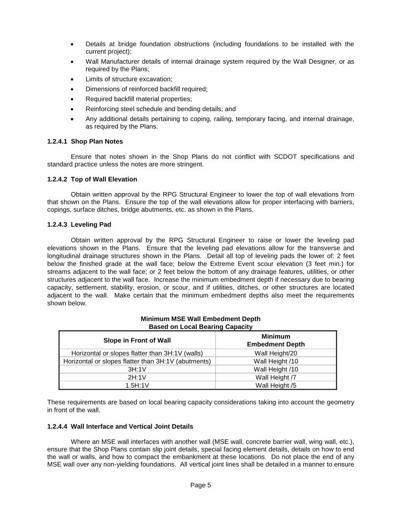
1.2.4.3 Leveling Pad Obtain written approval by the RPG Structural Engineer to raise or lower the leveling pad elevations shown in the Plans. Ensure that the leveling pad elevations allow for the transverse and longitudinal drainage structures shown in the Plans. Detail all top of leveling pads the lower of: 2 feet below the finished grade at the wall face; below the Extreme Event scour elevation (3 feet min.) for streams adjacent to the wall face; or 2 feet below the bottom of any drainage features, utilities, or other structures adjacent to the wall face. Increase the minimum embedment depth if necessary due to bearing capacity, settlement, stability, erosion, or scour, and if utilities, ditches, or other structures are located adjacent to the wall. Make certain that the minimum embedment depths also meet the requirements shown below.
Minimum MSE Wall Embedment Depth Based on Local Bearing Capacity
Slope in Front of Wall Minimum Embedment Depth
Horizontal or slopes flatter than 3H:1V (walls) Wall Height/20 Horizontal or slopes flatter than 3H:1V (abutments) Wall Height /10
3H:1V Wall Height /10 2H:1V Wall Height /7
1.5H:1V Wall Height /5 These requirements are based on local bearing capacity considerations taking into account the geometry in front of the wall. 1.2.4.4 Wall Interface and Vertical Joint Details Where an MSE wall interfaces with another wall (MSE wall, concrete barrier wall, wing wall, etc.), ensure that the Shop Plans contain slip joint details, special facing element details, details on how to end the wall or walls, and how to compact the embankment at these locations. Do not place the end of any MSE wall over any non-yielding foundations. All vertical joint lines shall be detailed in a manner to ensure
Page 6
that, for the life of the structure, the reinforced backfill does not migrate outside of the MSE wall system and the vertical joint is not wider than 1 inch. At locations where an MSE wall makes a 90 degree turn, use corner elements or corner blocks to make the turns. Show a detailed soil reinforcement layout where walls intersect (e.g., permanent MSE wall intersects a temporary MSE wall at 90 degrees or less).
1.2.4.5 Earth Surcharges If the Plans indicate an earth surcharge is to be placed over the reinforced zone, the surcharge may be retained by using a temporary MSE wall structure. If a two-stage wall construction method is being used, construct the surcharge as part of the first stage (temporary face) of the permanent wall and adjust as indicated in the Plans or as directed by the RCE.
1.2.4.6 Precast Concrete Panel Facing Layout For MSE walls with precast concrete panel facing, provide a numbered panel layout drawing for fabrication and erection purposes. 2. Materials 2.1 MSE Wall Facings Purchase or manufacture all applicable materials such as facing panel, facing block, connectors, facing aggregate, block fill, welded wire mesh baskets, and all other necessary components and install as per project requirements. 2.2 MSE Wall With Precast Concrete Panel Facings
2.2.1 Precast Concrete Panel Facing Provide precast concrete panels that are designed in accordance with Section 5 of the AASHTO LRFD Bridge Design Specifications, with the exceptions and additions listed in Subsections 2.2.1.1 through 2.2.1.10. 2.2.1.1 Size Provide precast concrete panels that have a maximum width (w) to height (h) ratio, w/h, that is less than or equal to 1.20 and that have a maximum height (h) to width (w) ratio, h/w, that is less than or equal to 1.20. Ensure that the maximum surface area of the panel does not exceed 30 square feet. The ratios do not apply to the top and bottom rows where smaller panels may be used. 2.2.1.2 Reinforcing Steel Provide reinforcing steel that meets the requirements of Section 703 of the SCDOT Standard Specifications. Ensure that fabrication and placement of reinforcing steel conforms to the applicable requirements of Section 703. Submit a manufacturer’s certification to the RCE that the reinforcing steel used in the facing panels is in conformance with this specification. 2.2.1.3 Concrete
Make certain that concrete and admixtures meet the requirements of applicable subsections of
Section 701 of the SCDOT Standard Specifications, except that a third party certification will be required from either ACPA or NPCA. Details of certification programs offered by ACPA are found at www.concrete-pipe.org and NPCA at www.precast.org. Provide concrete conforming to the requirements of Class 4000P with a minimum 28-day compressive strength of 4,000 psi. Provide leveling pad concrete conforming to the requirements of Class 2500 with a minimum 28-day compressive strength of 2,500 psi.
Page 7
2.2.1.4 Casting
Notify the SME at least 14 days before the production of precast concrete panels. Cast the panels on a flat surface, with the front face of the panel facing downward and the back face of the panel facing upward. Do not allow the tie strip guide or other galvanized devices to be in contact with or be attached to the face panel reinforcing steel.
Place the concrete in each panel without interruption and consolidate by the use of an approved
vibrator, supplemented by such hand tamping as may be necessary to force the concrete into the corners of the form. Fully support the units until the concrete reaches a minimum compressive strength of 1,000 psi. Cure the panels with burlap for 36 hours or steam cure. Keep the forms in place until they can be removed without damage to the panel. The panels may be shipped 3 days after casting and attainment of the required concrete compressive strength of 4,000 psi. 2.2.1.5 Compressive Strength Acceptance of the precast concrete panels with respect to compressive strength will be determined on a lot basis. A lot is defined as either 40 panels or a single day’s production, whichever is less. Randomly sample the lot for compressive strength testing in accordance with AASHTO T 141 and test in accordance with AASHTO T 22. Perform strength testing and acceptance in accordance with the applicable subsections of Section 701 of the SCDOT Standard Specifications. Reject panels represented by test cylinders that do not reach the above requirements. Submit testing results and a manufacturer’s certification to the RCE that the concrete used in the wall panels is in conformance with these specifications.
2.2.1.6 Markings
Clearly scribe the date of manufacture, the production lot number, and the panel identification number on the rear face of each panel.
2.2.1.7 Finish
Unless otherwise indicated in the Plans or directed by the RCE, ensure that the concrete surfacing for the front face has a deep fractured fin finish in accordance with Standard Drawing 701-950-01. Make certain all concrete finishes conform to the requirements of the applicable subsections of Section 702 of the SCDOT Standard Specifications. Provide the rear face with a uniform surface finish. Ensure that the rear face of the panel is roughly screeded to eliminate open pockets of aggregate and surface distortions in excess of 1/4 inch.
2.2.1.8 Tolerances
Manufacture precast concrete panels within the following tolerances: • Panel Dimensions: Position panel connection devices to within 1 inch of the specified
dimension. Ensure that all other dimensions are within 3/16 inch of the specified dimension. • Panel Squareness: Ensure that the difference between the two diagonals does not exceed
1/2 inch. • Panel Surface Finish: Ensure that surface defects on smooth formed surfaces measured over
a length of 5 feet does not exceed 1/8 inch. Ensure that surface defects on the textured-finish surfaces measured over a length of 5 feet does not exceed 5/16 inch.
Page 8
2.2.1.9 Rejection Panels will be rejected because of failure to meet any of the requirements specified above. In addition, any of the following defects are sufficient cause for rejection:
• Defects that indicate imperfect molding. • Defects indicating honeycomb or open texture concrete. • Cracked or severely chipped panels. • Color variation on front face of panel due to excess form oil or other reasons. • Defective or damaged reinforcement connection devices.
2.2.1.10 Handling, Storage and Shipping Handle, store, and ship panels in such a manner as to eliminate the dangers of chipping, discoloration, cracks, fractures, and excessive bending stresses. Support panels in storage on firm blocking located immediately adjacent to tie strips to avoid bending the tie strips.
2.2.2 Panel Joint Material Install bearing pads of the dimensions and thickness shown in the Plans or the accepted Shop Plans. Ensure that bearing pads placed in horizontal joints between panels are preformed Ethylene Propylene Diene Monomer (EPDM) rubber pads. Supply a manufacturer’s certification to the RCE that the bearing pad material conforms to ASTM D 2000 Grade 2, Type A, Class A with a Durometer Hardness of 55±5, or High Density Polyethylene (HDPE) pads with a minimum density of 0.946 g/cm3 in accordance with ASTM D 1505. Determine the stiffness (axial and lateral), size, and number of bearing pads such that the final joint opening shall be 3/4 ± 1/4 inch. Ensure the Wall Designer submits substantiating calculations verifying the stiffness (axial and lateral), size, and numbering of bearing pads assuming, as a minimum, a vertical loading at a given joint equal to 2 times the weight of facing panels directly above that level. As part of the substantiating calculations, have the Wall Designer submit results of certified laboratory tests in the form of vertical load-vertical strain and vertical load-lateral strain curves for the specific bearing pads proposed by the Wall Designer. The vertical load-vertical strain curve should extend beyond the first yield point of the proposed bearing pad. Cover all joints between panels on the back side of the wall with a geotextile meeting the requirements for filtration applications. Install the fabric cover in accordance with Subsection 4.5.
2.2.3 Panel Coping Place a cast-in-place or precast concrete cap over the upper most level of the precast concrete panels as detailed in the Plans. For cast-in-place coping, use Class 4000 concrete conforming to the requirements of Section 701 of the SCDOT Standard Specifications. For precast concrete coping, use Class 4000P concrete conforming to the requirements of Section 701. If necessary, place concrete to level up the top row of MSE wall precast concrete panel facings prior to placing panel coping. Ensure the bottom of the coping is parallel to the finished grade and projects low enough to fully cover the stepped joint line between the leveling concrete and the top of the wall facing elements. For leveling concrete below precast concrete coping, use Class 3000 concrete conforming to the requirements of Section 701. Provide reinforcing steel that meets the requirements of Section 703 of the SCDOT Standard Specifications. Ensure that fabrication and placement of reinforcing steel conforms to the applicable requirements of Section 703. Submit a manufacturer’s certification to the RCE that the concrete and reinforcing steel used in the panel coping are in conformance with these specifications. Locate all expansion and contraction joints to coincide with panel joints.
Page 9
2.3 MSE Wall With Modular Concrete Block Facings
2.3.1 Modular Concrete Block Facing Submit a manufacturer’s certification to the RCE that the modular concrete blocks for each lot shipped are in conformance with the following specifications. For each particular lot shipped, ensure that the certification for each shipment lists the date manufactured, type of block, the average compressive strength, and the water absorption.
2.3.1.1 Concrete Use Portland Cement Concrete with a minimum 28 day compressive strength of 4,000 psi. Limit maximum water absorption to 5% in accordance with ASTM C 140. Ensure that admixtures conform to the requirements in applicable subsections of Section 701 of the SCDOT Standard Specifications.
2.3.1.2 Casting Cast the modular concrete blocks in steel molds and in a manner that will ensure the production of uniform modular concrete blocks. Place the concrete in each block without interruption and consolidate. Steam cure the blocks for a minimum of 24 hours. Make certain the blocks reach a minimum compressive strength of 4,000 psi before being shipped.
2.3.1.3 Compressive Strength Acceptance of the modular concrete blocks with respect to compressive strength is determined on a per lot basis. The maximum number of blocks in each lot is the lesser of 2,000 or a single day’s production. Randomly sample the lot in accordance with ASTM C 140. Have the Wall Manufacturer perform compressive strength tests on test specimens prepared by the manufacturer. Ensure that the compressive strength test specimens conform to the saw-cut coupon provisions of Subsection 5.2.4 of ASTM C 140. Block lots will be approved when the average compressive strength is 4,000 psi of 3 test coupons and with no individual test having a compressive strength less than 3,500 psi. Block lots not reaching the above requirements will be rejected.
2.3.1.4 Markings Clearly mark on each lot the date of manufacture, lot number, and type of block in accordance with the approved MSE wall Shop plans.
2.3.1.5 Finish Unless otherwise indicated in the Plans or directed by the RCE, provide on the front face of the blocks a natural gray roughened surface (granite) finish in accordance with Standard Drawing 701-950-01.
2.3.1.6 Tolerances Provide modular concrete blocks manufactured within the following tolerances:
• Ensure that the length and width of each individual block is within 1/8 inch of the specified dimension.
• Ensure that hollow units have a minimum wall thickness of 1-1/4 inch. • Ensure that the height of each individual block is within 1/16 inch of the specified dimension. • When a broken or fractured face is required, ensure that the horizontal dimension of the front
face is within 1 inch of the theoretical dimension of the individual block shown in the Plans.
Page 10
2.3.1.7 Rejection Modular concrete blocks will be rejected because of failure to meet any of the requirements specified above. In addition, any of the following defects will be sufficient cause for rejection:
• Defects that indicate imperfect molding. • Defects indicating honeycomb or open texture concrete. • Cracks greater than 0.02 inches in width and longer than 25% of the height of the block. • Severely chipped or broken blocks. • Color variation on front face of block due to excess form oil or other reasons. • Defective or damaged reinforcement connection devices built into the modular concrete
block.
2.3.1.8 Handling, Storage and Shipping Handle, store, and ship modular concrete blocks in such a manner as to eliminate the dangers of chipping, discoloration, cracks, or fractures.
2.3.2 Block Fill Furnish block fill in accordance with Subsection 2.5.4 when modular concrete blocks require a block fill for connection strength or when vertical void spaces exist within the modular concrete block. 2.3.3 Free Draining Aggregate
Provide a 12-inch thick free draining aggregate layer with a geotextile fabric when a granular
backfill is used with modular concrete block facings. In addition to the 12-inch aggregate layer, fill any void spaces along the backside of the modular concrete blocks with aggregate.
2.3.4 Block Coping
Place a cast-in-place concrete coping over the upper most level of modular concrete blocks as indicated in the Plans or as shown on the accepted Shop Plans. Provide Class 4000 concrete conforming to applicable subsections of Section 701 of the SCDOT Standard Specifications. Use reinforcing steel that meets the requirements of Section 703 of the SCDOT Standard Specifications. Ensure that fabrication and placement of reinforcing steel conforms to the applicable requirements of Section 703. Submit a manufacturer’s certification to the RCE that the concrete and reinforcing steel used in the block coping are in conformance with these specifications. 2.4 MSE Wall Temporary Facing
2.4.1 Welded Wire Mesh Facing Furnish reinforcing mesh that is shop-fabricated of cold drawn steel wire. Supply a manufacturer’s certification to the RCE that the material conforms to the requirements of AASHTO M 32, has been welded into the finished mesh fabric in accordance with the requirements of AASHTO M 55, and galvanization conforms to the minimum requirements of AASHTO M 111. Apply galvanization after the mesh is fabricated.
2.4.2 Temporary Facing Drainage Fabric Provide the temporary geotextile drainage fabric as detailed in the Plans. Use geotextile meeting the requirements for filtration applications.
Page 11
2.5 Reinforced Backfill Material 2.5.1 General
Provide either granular or stone backfill for the reinforced backfill material for permanent MSE
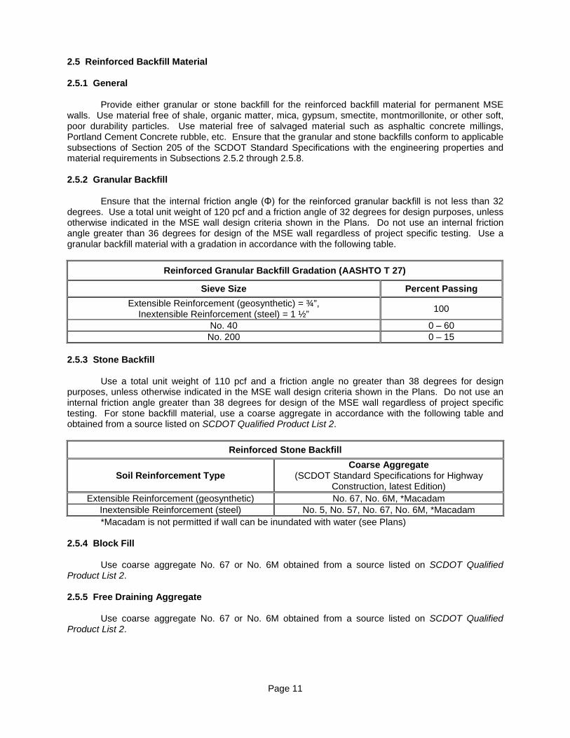
walls. Use material free of shale, organic matter, mica, gypsum, smectite, montmorillonite, or other soft, poor durability particles. Use material free of salvaged material such as asphaltic concrete millings, Portland Cement Concrete rubble, etc. Ensure that the granular and stone backfills conform to applicable subsections of Section 205 of the SCDOT Standard Specifications with the engineering properties and material requirements in Subsections 2.5.2 through 2.5.8. 2.5.2 Granular Backfill Ensure that the internal friction angle (Φ) for the reinforced granular backfill is not less than 32 degrees. Use a total unit weight of 120 pcf and a friction angle of 32 degrees for design purposes, unless otherwise indicated in the MSE wall design criteria shown in the Plans. Do not use an internal friction angle greater than 36 degrees for design of the MSE wall regardless of project specific testing. Use a granular backfill material with a gradation in accordance with the following table.
Reinforced Granular Backfill Gradation (AASHTO T 27)
Sieve Size Percent Passing Extensible Reinforcement (geosynthetic) = ¾”,
Inextensible Reinforcement (steel) = 1 ½” 100
No. 40 0 – 60 No. 200 0 – 15
2.5.3 Stone Backfill
Use a total unit weight of 110 pcf and a friction angle no greater than 38 degrees for design
purposes, unless otherwise indicated in the MSE wall design criteria shown in the Plans. Do not use an internal friction angle greater than 38 degrees for design of the MSE wall regardless of project specific testing. For stone backfill material, use a coarse aggregate in accordance with the following table and obtained from a source listed on SCDOT Qualified Product List 2.
Reinforced Stone Backfill
Soil Reinforcement Type Coarse Aggregate
(SCDOT Standard Specifications for Highway Construction, latest Edition)
Extensible Reinforcement (geosynthetic) No. 67, No. 6M, *Macadam Inextensible Reinforcement (steel) No. 5, No. 57, No. 67, No. 6M, *Macadam *Macadam is not permitted if wall can be inundated with water (see Plans)
2.5.4 Block Fill Use coarse aggregate No. 67 or No. 6M obtained from a source listed on SCDOT Qualified Product List 2.
2.5.5 Free Draining Aggregate Use coarse aggregate No. 67 or No. 6M obtained from a source listed on SCDOT Qualified Product List 2.
Page 12
2.5.6 Soil Property Requirements For Backfill Ensure that all reinforced backfill (granular or stone), block fill, and free draining aggregate have the following soil properties:
• pH values between 5.0 and 10.0 for metallic reinforcements, pH values between 3.0 and 9.0
for polyester, and pH values greater than 3.0 for polypropylene and high density polyethylene. For granular backfill, determine pH values in accordance with AASHTO T 289. For stone backfill, prepare sample as follows: Obtain approximately 2-1/2 pounds of representative material. Transfer the sample into a 1 gallon wide mouth plastic jug. Add an equal weight of deionized or distilled water to the sample and let the mixture sit for approximately 30 minutes. At the end of this period, place a lid on the container and vigorously agitate the mixture for 3 minutes. Repeat agitation 2 hours after the initial agitation and again 4 hours after the initial agitation. After the agitation at the 4-hour time interval, allow the sample to sit for approximately 20 hours to allow for any solids to settle out. After the sample sits for 20 hours, remove a sufficient amount of the solution and filter through a coarse paper (such as Fisher Q8) to obtain the supernate to be analyzed. Analyze the supernate according to ASTM D 1293 and ASTM D 1125.
• Organic content not to exceed 1.0 percent (weight of organic material to weight of total
sample) as determined by AASHTO T 267 for material finer than No. 10 sieve. • Internal friction angle not less than the values specified in Subsections 2.5.2 and 2.5.3 as
determined by the standard direct shear test (AASHTO T 236) or the triaxial test (AASHTO T 297) on the portion passing the No. 10 sieve. Compact material test samples to 95% (AASHTO T 99, Method C or D) of maximum density at optimum moisture content. Internal friction angle testing of backfills meeting the requirements of Subsection 2.5.3 (Stone Backfill) is not required.
• The reinforced backfill material shall have a soundness loss of 30 percent or less when
tested in accordance with AASHTO T 104 using magnesium sulfate solution with a test duration of four cycles. Alternatively, the material shall have a soundness loss of 15 percent or less when tested in accordance with AASHTO T 104 using a sodium sulfate solution with a test duration of five cycles.
• For granular material, Coefficient of uniformity, Cu, that is greater than 4 but less than 20.
Compute the coefficient of uniformity, Cu, as follows:
10
60
DDCu =
Where: D60 is the particle diameter at 60% passing and D10 is the particle diameter at 10% passing.
• Plasticity Index (PI) less than or equal to 6 and the Liquid Limit (LL) less than or equal to 30
as determined by AASHTO T 90.
• Classified as well-graded in accordance with the Unified Soil Classification System (USCS) in ASTM D 2487. The reinforced backfill material shall not be gap-graded.
• If metallic soil reinforcements are used, the resistivity of the reinforced backfill and modular
concrete block fill shall be greater than or equal to 5,000 ohm-cm (AASHTO T 288).
Page 13
2.5.7 Temporary MSE Wall Reinforced Backfill For a temporary MSE wall that interfaces with the reinforced backfill of a permanent MSE wall, use the same type of reinforced backfill that is used in the permanent MSE wall.
2.5.8 Testing Frequency Test soil properties during initial source evaluation or if a change in source. Sample reinforced backfill material once every 2,000 cubic yards and test for gradation and pH. Sample reinforced backfill material once every 15,000 cubic yards and test for internal friction angle, organic content, and resistivity. A variation in testing frequency may be required if a variation in material gradation or composition is observed.
2.6 Soil Reinforcements and Attachment Devices 2.6.1 General Purchase or manufacture all applicable materials such as soil reinforcements, attachment devices, and all other necessary components. 2.6.2 Inextensible Soil Reinforcement 2.6.2.1 General Make certain inextensible reinforcement conforms to the required shape and dimensions and is free of defects that may impair its strength and durability. Provide a mill test report to the RCE with each shipment. Sample and test reinforcement from each heat number. Ensure minimum galvanization coating of 2.0 oz/sq.ft. Submit a signed certification to the RCE that all inextensible soil reinforcement is in conformance with these specifications. 2.6.2.2 Reinforcing Steel Strips Provide galvanized reinforcing strips that are hot rolled from bars to the required shape and dimensions. Ensure that their physical and mechanical properties conform to ASTM A 572, Grade 65 minimum. Ensure galvanization conforms to the requirements of AASHTO M 111. 2.6.2.3 Metallic Reinforcing Mesh
Provide galvanized reinforcing mesh that is shop-fabricated of cold drawn steel wire conforming
to the requirements of AASHTO M 32, and welded into the finish mesh fabric in accordance with AASHTO M 55. Apply galvanization after the mesh is fabricated, and ensure that it conforms to the requirements of AASHTO M 111.
2.6.2.4 Bar Mats
Fabricate bar mats from AASHTO M 270, Grade 36 steel. Apply galvanization after the bar mats
and connector pins have been welded. Ensure that galvanization conforms to the requirements of AASHTO M 111 or M 232 as applicable.
2.6.2.5 Galvanization Damage
Repair damage done to the galvanization prior to the soil reinforcement installation in accordance
with ASTM A 780.
Page 14
2.6.3 Extensible Soil Reinforcement
2.6.3.1 General Ensure that reinforcing conforms to the required shape and dimensions and is free of defects that may impair its strength and durability.
2.6.3.2 Geosynthetic Soil Reinforcement Use geosynthetic soil reinforcement meeting the design requirements shown in the Plans and specified in the Shop Plans. Ensure that geotextile reinforcement is a woven geotextile consisting only of long chain polymeric filaments or yarns formed into a stable network. Ensure that geogrid reinforcements are a regular network of integrally connected polymer tensile elements with aperture geometry sufficient to permit significant mechanical interlock with the surrounding backfill material. Provide geosynthetic reinforcements having a structure that is dimensionally stable and able to retain its geometry under construction stresses and that have high resistance to damage during construction, to ultraviolet degradation, and to all forms of chemical and biological degradation encountered in the soil being reinforced.
2.6.3.3 Delivery, Storage, and Handling of Geosynthetic Materials Check the geosynthetic soil reinforcement upon delivery to ensure that the proper material has been received. Make certain that geosynthetic rolls are labeled per ASTM D 4873. During all periods of shipment and storage, protect the geosynthetic materials from temperatures greater than 140ºF, mud, dirt, dust, and debris. Follow the manufacturer's recommendations regarding protection from direct sunlight. At the time of installation, the geosynthetic material will be rejected if it has defects, tears, punctures, flaws, deterioration, or damage incurred during manufacturing, transportation, or storage. At no additional cost to the Department, replace any geotextile fabric or geosynthetic reinforcement damaged during storage or installation. 2.6.3.4 Manufacturing Quality Control Submit to the RCE a manufacturing quality control certificate and conformance testing results for all geosynthetic soil reinforcement delivered to the site. Perform sampling and conformance testing in accordance with ASTM D 4354. Base geosynthetic product acceptance on ASTM D 4759. For all geosynthetic soil reinforcement, provide conformance testing of ultimate tensile strength, Tult, in accordance with Subsection 2.7. Ensure that the quality control certificate includes roll numbers and identification, sampling procedures, and results of the conformance testing with a description of test methods used. Include a signed certification to the RCE that all extensible soil reinforcement is in conformance with these specifications with the submitted quality control certificate. 2.6.4 Reinforcement Attachment Devices 2.6.4.1 General Make certain all reinforcing attachment devices conform to the required shape and dimensions and are free of defects that may impair their strength, durability, and functionality. Submit a manufacturer’s certification to the RCE that the materials are in conformance with this specification.
2.6.4.2 Tie Strips Provide tie strips that are shop fabricated of hot-rolled steel conforming to the requirements of ASTM A 1011, Grade 50 minimum. Use a bending radius that is greater than or equal to 3/8 inch. Apply galvanization after the strips are fabricated, inclusive of punch holes for bolts. Galvanization shall conform to the requirements of AASHTO M 111.
Page 15
2.6.4.3 Fasteners
Furnish connection hardware conforming to the requirements shown in the approved Shop Plans.
Cast connection hardware in the precast concrete panels such that all connectors are in alignment and able to transfer full and even load to the soil reinforcement. Ensure fasteners consist of hexagonal cap screw bolts and nuts conforming to the requirements of ASTM A 325, ASTM A 449, or equal. Galvanize in accordance with AASHTO M 232.
2.6.4.4 Connector Pins Fabricate connector pins from AASHTO M 270, Grade 36, steel and weld to the soil reinforcement mats as shown on the Shop Plans. Galvanize in accordance with AASHTO M 111. Fabricate connector bars from cold drawn steel wire conforming to the requirements of AASHTO M 32 and galvanize in accordance with AASHTO M 111. 2.6.4.5 Turn-Buckle Connectors For permanent walls that are indicated in the Plans to be constructed using two-stage construction methods, provide connection hardware conforming to the requirements shown in the approved Shop Plans. Determine the size and type of the turn-buckles and the number of connectors considering the facing panel size, distance between the two facing units, the type of infill used, and the amount of relative settlement anticipated between the two facing systems after the second stage facing is constructed. Cast connection hardware in the precast concrete panels such that all connectors are in alignment and able to transfer full and even load to the soil reinforcement. Ensure fasteners consist of hexagonal cap screw bolts and nuts conforming to the requirements of ASTM A 325, ASTM A 449, or equal. Galvanize in accordance with AASHTO M 232. 2.7 MSE Wall System Certification Package 2.7.1 Geosynthetic Soil Reinforcements When geosynthetic soil reinforcements are used for construction of MSE walls, submit to the RCE an MSE Wall System Certification Package prepared by the Wall Manufacturer. This Certification Package is for the MSE wall system. Other Certification requirements for individual components of the MSE wall are included in other sections of these specifications. Include a statement in the MSE Wall System Certification Package that the furnished geosynthetic and the connection between the geosynthetic and the wall facing meets the design requirements as stated on the approved Shop Plans. Perform any tests required at no additional cost to the Department and in conformance with the testing requirements found in FHWA-NHI-10-025, “Design and Construction of Mechanically Stabilized Earth Walls and Reinforced Soil Slopes – Volume II”, 2009. If in the opinion of the Department, the required documentation is not provided for individual reduction factors (RF) or pullout coefficients (F*, α), use default values for these design parameters in accordance with this specification. Include in the MSE Wall System Certification Package a Certificate of Compliance that certifies the following (as applicable to the MSE wall system):
• The nominal long-term reinforcement design strength, Tal, for geosynthetic soil
reinforcements. • The ultimate tensile strength, Tult, (Minimum Average Roll Value-MARV) for geosynthetic soil
reinforcements. • The strength reduction factors, CRCR and RFD, for the long-term connection strength between
geosynthetic soil reinforcement and modular block facing. • The strength reduction factors, RFID, RFCR, and RFD, for the long-term geosynthetic soil
reinforcement tensile strength.
Page 16
• The geosynthetic’s pullout coefficients, F* and α, meet or exceed the MSE wall's required
design pullout coefficients. Document that the certified values for the items above meet the minimum requirements outlined in Article 11.10 of AASHTO LRFD Bridge Design Specifications. 2.7.2 Metallic Soil Reinforcements When metallic soil reinforcements are used for construction of MSE walls, submit to the RCE an MSE Wall System Certification Package prepared by the Wall Manufacturer. This Certification Package is for the MSE wall system. Other Certification requirements for individual components of the MSE wall are included in other sections of these specifications. Include in the certification a mill test report containing the ultimate tensile strength for the soil reinforcement. Also include a mill test report containing the galvanization coverage. For metallic mesh wall reinforcement, include a mill test report containing the ultimate weld strength for the soil reinforcement. 2.8 Miscellaneous Construction Materials 2.8.1 Leveling Pad Construct an unreinforced cast-in-place concrete leveling pad as shown in the Plans using Class 2500 concrete conforming to the applicable requirements of Section 701 of the SCDOT Standard Specifications.
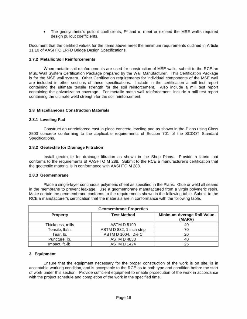
2.8.2 Geotextile for Drainage Filtration Install geotextile for drainage filtration as shown in the Shop Plans. Provide a fabric that conforms to the requirements of AASHTO M 288. Submit to the RCE a manufacturer’s certification that the geotextile material is in conformance with AASHTO M 288. 2.8.3 Geomembrane Place a single-layer continuous polymeric sheet as specified in the Plans. Glue or weld all seams in the membrane to prevent leakage. Use a geomembrane manufactured from a virgin polymeric resin. Make certain the geomembrane conforms to the requirements shown in the following table. Submit to the RCE a manufacturer’s certification that the materials are in conformance with the following table.
Geomembrane Properties
Property Test Method Minimum Average Roll Value (MARV)
Thickness, mills ASTM D 5199 40 Tensile, lb/in. ASTM D 882, 1 inch strip 70
Tear, lb. ASTM D 1004, Die C 20 Puncture, lb. ASTM D 4833 40 Impact, ft.-lb. ASTM D 1424 25
3. Equipment Ensure that the equipment necessary for the proper construction of the work is on site, is in acceptable working condition, and is acceptable to the RCE as to both type and condition before the start of work under this section. Provide sufficient equipment to enable prosecution of the work in accordance with the project schedule and completion of the work in the specified time.
Page 17
4. Construction 4.1 Wall Excavation and Foundation Preparation Prepare wall excavation and foundation in accordance with Section 204 of the SCDOT Standard Specifications. In addition to the requirements of Section 204, proof roll the area where the MSE wall will be constructed with a minimum of 5 passes by pneumatic tire equipment weighing a minimum of 8 tons.
4.2 Leveling Pad Construction At each MSE wall foundation level, provide a cast-in-place unreinforced concrete leveling pad as shown in the Plans. Cure the leveling pad a minimum of 12 hours before placement of wall facing panels or blocks. If the permanent MSE wall facing is to be installed in front of a temporary MSE wall facing, install the leveling pad just prior to construction of the permanent MSE wall facing. Construct top surface of leveling pad so it is level in both directions. Reject leveling pad when top surface deviates from level by more than 1/8 inch in 10 feet, except at designated steps in the leveling pad shown on the Plans or accepted Shop Plans.
4.3 MSE Wall System Supplier's Assistance and Samples Have the Wall Manufacturer and Wall Designer provide qualified and experienced advisory personnel at the start of the wall construction and until such time that the RCE believes the SCDOT inspectors and the Contractor's personnel are adequately acquainted with the MSE wall construction procedures and no longer require technical assistance. Ensure that the representatives are also available on an as needed basis, as requested by the RCE, throughout the construction of the MSE wall structures. Provide the RCE with three MSE wall field installation manuals, specific to the MSE wall type being constructed. If the MSE wall is reinforced with geosynthetics, provide the RCE with two sets of samples (approx. 1 square foot each) of each type of geosynthetic soil reinforcement that will be used. Ensure that each sample has a durable tag attached to it, stating the geosynthetic manufacturer and type/model. 4.4 Internal Drainage System Install an internal drainage system behind the wall as indicated in the Plans and Shop Plans. Place outlet pipes at sags in the flow line, at the low end of the collector pipe, and at other locations as shown or specified. Determine the location and elevation of the internal drainage system and include the details in the Shop Plans. Form openings for weep holes in precast facing panels prior to casting the panels.
4.5 Location of Geotextile Fabric For MSE walls with precast concrete panel facings, provide a geotextile fabric covering all joints between panels on the backside of the wall, including the joint along the leveling pad. Make certain the geotextile fabric has a minimum width of 12 inches and overlaps adjacent geotextile fabrics a minimum of 4 inches. Adhere the geotextile fabric to the panels by applying adhesive to the back of the panel on each side of the joint. Do not apply adhesive directly on the geotextile fabric or within 2 inches of the panel joint edge.
For MSE walls with modular concrete block facings and granular reinforced backfill, place a
geotextile between the free draining aggregate and the reinforced backfill. If a reinforced stone backfill is used, place the geotextile between the reinforced backfill and the retained backfill as shown in the Plans.
If required in the Plans, place geotextile fabric between the natural ground and the reinforced
backfill. Ensure that the subgrade to receive the geotextile fabric is free of loose or extraneous material and sharp objects that may damage the geotextile fabric during installation. Stretch, align, and place the
Page 18
geotextile fabric in a wrinkle-free manner and ensure that it has intimate contact with the soil. Overlap adjacent geotextile fabric edges a minimum of 1.5 feet.
At the direction of the RCE, repair or replace torn or punctured sections of the geotextile fabric.
Cut out geotextile fabric damaged during installation by tearing or puncturing and completely replace or repair by placing a piece of fabric that is large enough to cover the damaged area. Provide a sufficient overlap, 1.5 feet minimum, on all sides to secure the damaged geotextile fabric area.
4.6 Wall Erection Place precast concrete panels and modular concrete block facings so that their final position is vertical or battered as shown in the Shop Plans. Place precast concrete panels and modular concrete block facings in successive horizontal lifts. Construct the MSE wall structure using a predetermined backward batter corresponding to the anticipated outward wall deflection due to the active soil pressures. Have the Wall Designer determine this backward batter, show it on the Shop Plans, and adjust during construction as needed to build the wall to the required construction tolerances. A negative slope or batter (sloping outward from the face) will not be acceptable regardless of the wall tolerance achieved.
Handle MSE wall precast concrete panels by a lifting device set into the upper edge of the panels
or as indicated in the Shop Plans. Place the first level of precast concrete panels directly on the concrete leveling pad. Do not use horizontal joint material or wooden shims between the first course of panels and the leveling pad. Provide external bracing for the first lift of precast concrete panels. As backfill material is placed behind a panel, maintain the panel in position by means of temporary wooden wedges or bracing in accordance with the MSE Wall Manufacturer’s recommendations. Remove the wooden wedges as soon as the panel above the wedged panel is completely erected and backfilled. Backfill in front of wall and above leveling pad to prevent erosion or ponding of water. Prevent water from standing adjacent to leveling pad.
For permanent walls that are indicated in the Plans to be constructed using two-stage
construction methods, use the following construction sequence: • Install settlement monitoring instrumentation in accordance with the Plans prior to
commencement of two-stage MSE wall construction. • Construct the MSE wall with temporary welded wire mesh facing as indicated in the Plans to
allow for settlement to occur. Locate welded wire mesh facing to allow construction of the second stage of the permanent MSE wall facing.
• After the RCE in consultation with the RPG Geotechnical Engineer has determined sufficient
settlement has occurred, the Department will provide written notice to proceed with the construction of permanent facing.
• Construct the MSE wall leveling pad at the location of the permanent wall facing. • Place the permanent wall facing and attach connections to the soil reinforcement as indicated
in the MSE wall details included in the accepted Shop Plans. • As the permanent facing is being placed, backfill the space between the temporary and the
permanent facings. • Backfill in front of wall and above leveling pad to prevent erosion or ponding of water.
Prevent water from standing adjacent to leveling pad.
Page 19
4.7 Joint Material Install joint material to the dimensions and thickness shown in the Plans, or the accepted Shop Plans. 4.8 Reinforced Backfill Placement Closely follow the erection of each lift of facing elements with the backfill placement. At each level of soil reinforcement, roughly level the backfill material to an elevation approximately 1-2 inches above the level of the connection at the facing before placing the soil reinforcement. Place backfill in such a manner as to avoid any damage or disturbance of the wall materials. Remove and replace, at the Contractor’s expense, all wall materials that become damaged during backfill placement. Make certain that the backfill placement methods near the facing do not create voids directly beneath the reinforcing elements.
Construct the reinforced embankment in accordance with applicable subsections of Section 205
of the SCDOT Standard Specifications. Compact reinforced backfill to meet the design requirements but not less to than 95.0 percent of the maximum dry density in accordance with AASHTO T 99. Perform compaction control testing of the reinforced backfill with a minimum frequency of one density test per every two lifts for every 25 feet of wall at bridge abutments (any portion of wall within 150 feet of a bridge) and every 100 feet of wall along roadways (more than 150 feet away from a bridge).
Compact stone backfill material with a minimum of 4 passes with a smooth heavy roller
(approximately 15 tons). Compaction testing will not be required for stone backfill material. Do not use sheepsfoot or grid-type rollers for compacting backfill within the reinforced backfill.
Achieve compaction within 3 feet of the back face of the wall, pipe encased pile, or pile, by at least three passes of a lightweight walk behind vibratory plate or roller. In order to determine the number of passes needed to compact the area within 3 feet of the back face of the wall, establish a test strip area 3 feet or farther from the back face of the wall, measuring a minimum of 3 feet by 5 feet within the reinforced backfill and compact it with a lightweight walk behind vibratory plate or roller. Ensure that the moisture content of the backfill material prior to and during compaction is uniformly distributed throughout each layer. Place stone backfill in 6 inch lifts within 3 feet of the back face of the wall and compact by at least four passes of a lightweight walk behind vibratory plate or roller.
Ensure that the backfill materials have a placement moisture content not more than 2 percentage points below the optimum moisture content and not more than the optimum moisture content. Remove and rework backfill material with placement moisture content in excess of the optimum moisture content until the moisture content is uniformly acceptable throughout the entire lift.
Make certain the maximum soil lift thickness (loose) is 8 inches and closely follows the MSE wall facing erection. Place stone backfill in 6 inch to 12 inch lift thickness (loose). Decrease this lift thickness if necessary to obtain the required density. Accomplish backfill compaction without disturbance or distortion of the reinforcement. Maintain a minimum of 6 inches of backfill material at all times between the compaction equipment and the soil reinforcement.
At the end of each day's operations, shape the last level of backfill to permit runoff of rainwater
away from the wall face. In addition, do not allow surface runoff from adjacent areas to enter the wall reinforcement zone until this zone is protected from infiltration. Repair any damage or movement caused by erosion, sloughing, or saturation of the reinforced backfill or retained backfill at no expense to the Department.
Page 20
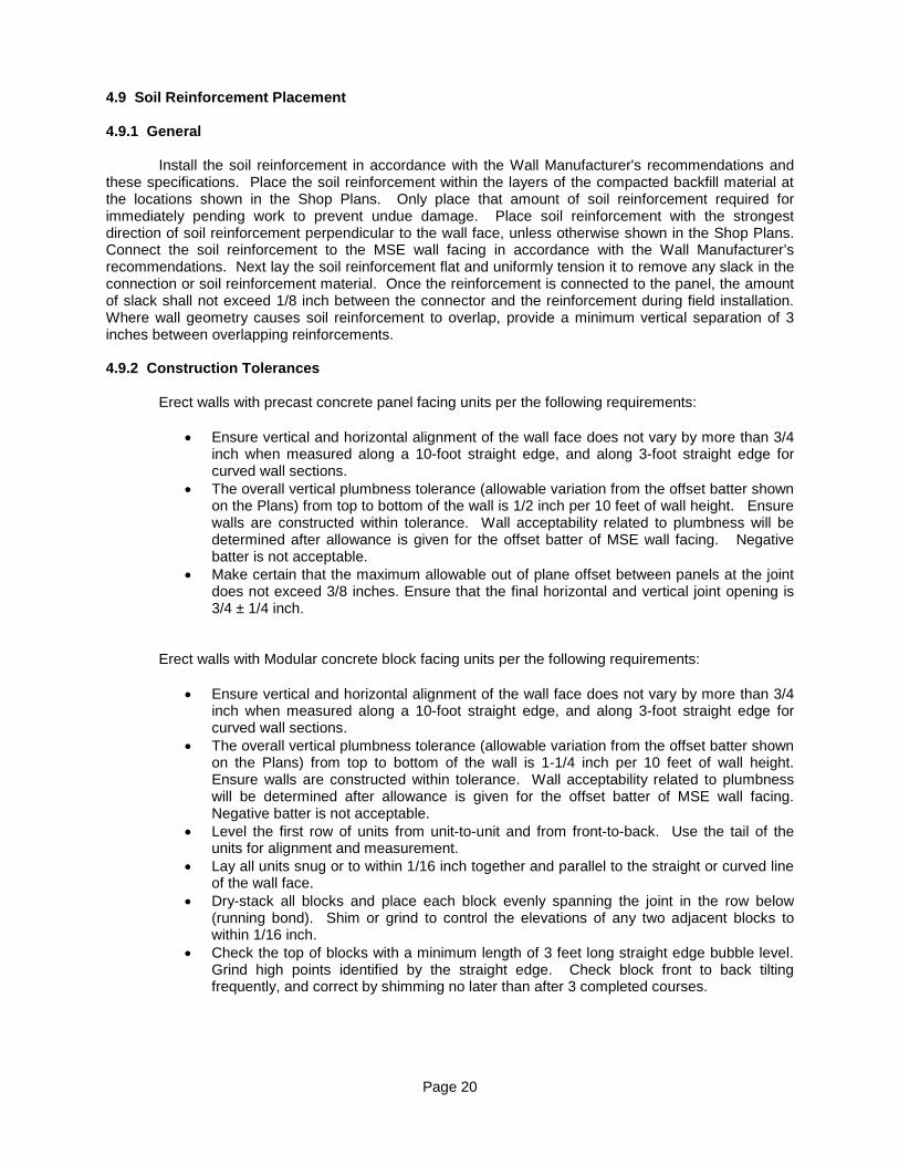
4.9 Soil Reinforcement Placement 4.9.1 General Install the soil reinforcement in accordance with the Wall Manufacturer's recommendations and these specifications. Place the soil reinforcement within the layers of the compacted backfill material at the locations shown in the Shop Plans. Only place that amount of soil reinforcement required for immediately pending work to prevent undue damage. Place soil reinforcement with the strongest direction of soil reinforcement perpendicular to the wall face, unless otherwise shown in the Shop Plans. Connect the soil reinforcement to the MSE wall facing in accordance with the Wall Manufacturer’s recommendations. Next lay the soil reinforcement flat and uniformly tension it to remove any slack in the connection or soil reinforcement material. Once the reinforcement is connected to the panel, the amount of slack shall not exceed 1/8 inch between the connector and the reinforcement during field installation. Where wall geometry causes soil reinforcement to overlap, provide a minimum vertical separation of 3 inches between overlapping reinforcements. 4.9.2 Construction Tolerances
Erect walls with precast concrete panel facing units per the following requirements:
• Ensure vertical and horizontal alignment of the wall face does not vary by more than 3/4 inch when measured along a 10-foot straight edge, and along 3-foot straight edge for curved wall sections.
• The overall vertical plumbness tolerance (allowable variation from the offset batter shown on the Plans) from top to bottom of the wall is 1/2 inch per 10 feet of wall height. Ensure walls are constructed within tolerance. Wall acceptability related to plumbness will be determined after allowance is given for the offset batter of MSE wall facing. Negative batter is not acceptable.
• Make certain that the maximum allowable out of plane offset between panels at the joint does not exceed 3/8 inches. Ensure that the final horizontal and vertical joint opening is 3/4 ± 1/4 inch.
Erect walls with Modular concrete block facing units per the following requirements:
• Ensure vertical and horizontal alignment of the wall face does not vary by more than 3/4 inch when measured along a 10-foot straight edge, and along 3-foot straight edge for curved wall sections.
• The overall vertical plumbness tolerance (allowable variation from the offset batter shown on the Plans) from top to bottom of the wall is 1-1/4 inch per 10 feet of wall height. Ensure walls are constructed within tolerance. Wall acceptability related to plumbness will be determined after allowance is given for the offset batter of MSE wall facing. Negative batter is not acceptable.
• Level the first row of units from unit-to-unit and from front-to-back. Use the tail of the units for alignment and measurement.
• Lay all units snug or to within 1/16 inch together and parallel to the straight or curved line of the wall face.
• Dry-stack all blocks and place each block evenly spanning the joint in the row below (running bond). Shim or grind to control the elevations of any two adjacent blocks to within 1/16 inch.
• Check the top of blocks with a minimum length of 3 feet long straight edge bubble level. Grind high points identified by the straight edge. Check block front to back tilting frequently, and correct by shimming no later than after 3 completed courses.
Page 21
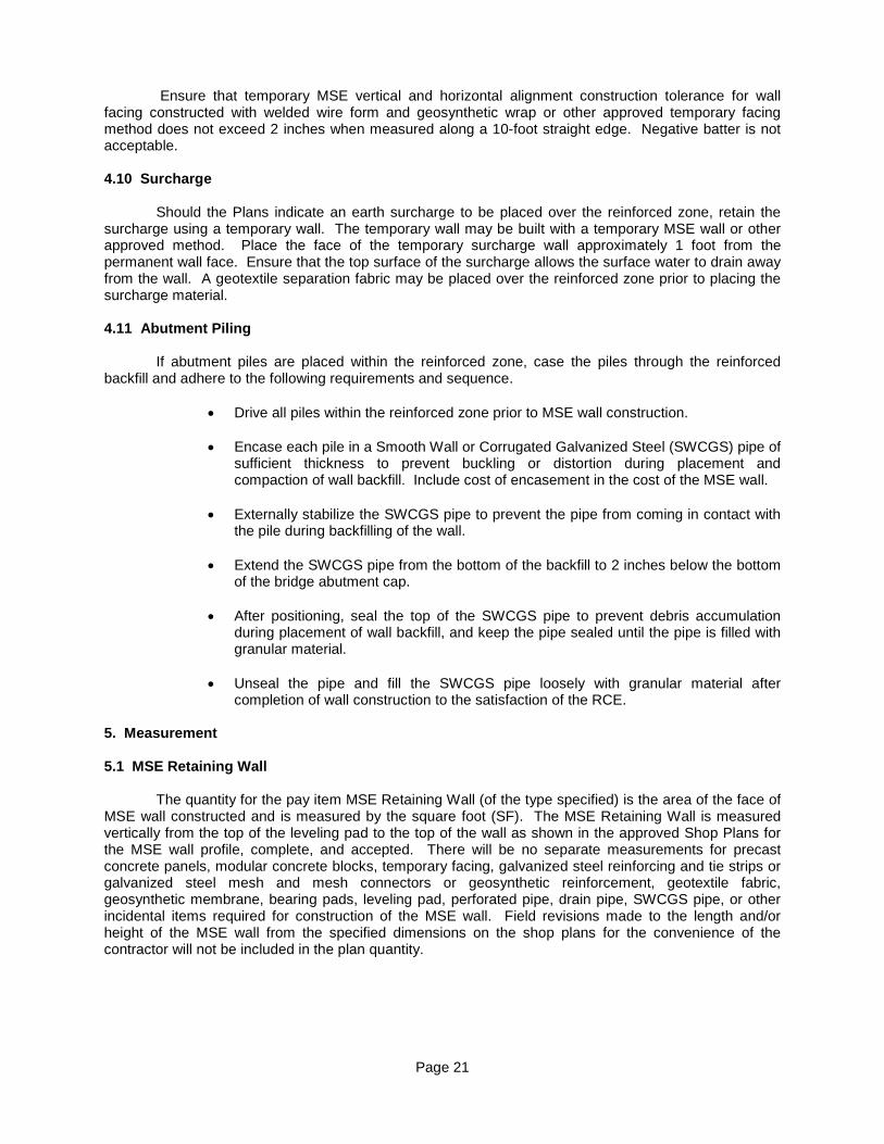
Ensure that temporary MSE vertical and horizontal alignment construction tolerance for wall facing constructed with welded wire form and geosynthetic wrap or other approved temporary facing method does not exceed 2 inches when measured along a 10-foot straight edge. Negative batter is not acceptable. 4.10 Surcharge Should the Plans indicate an earth surcharge to be placed over the reinforced zone, retain the surcharge using a temporary wall. The temporary wall may be built with a temporary MSE wall or other approved method. Place the face of the temporary surcharge wall approximately 1 foot from the permanent wall face. Ensure that the top surface of the surcharge allows the surface water to drain away from the wall. A geotextile separation fabric may be placed over the reinforced zone prior to placing the surcharge material.
4.11 Abutment Piling If abutment piles are placed within the reinforced zone, case the piles through the reinforced backfill and adhere to the following requirements and sequence.
• Drive all piles within the reinforced zone prior to MSE wall construction. • Encase each pile in a Smooth Wall or Corrugated Galvanized Steel (SWCGS) pipe of
sufficient thickness to prevent buckling or distortion during placement and compaction of wall backfill. Include cost of encasement in the cost of the MSE wall.
• Externally stabilize the SWCGS pipe to prevent the pipe from coming in contact with
the pile during backfilling of the wall. • Extend the SWCGS pipe from the bottom of the backfill to 2 inches below the bottom
of the bridge abutment cap. • After positioning, seal the top of the SWCGS pipe to prevent debris accumulation
during placement of wall backfill, and keep the pipe sealed until the pipe is filled with granular material.
• Unseal the pipe and fill the SWCGS pipe loosely with granular material after
completion of wall construction to the satisfaction of the RCE. 5. Measurement 5.1 MSE Retaining Wall The quantity for the pay item MSE Retaining Wall (of the type specified) is the area of the face of MSE wall constructed and is measured by the square foot (SF). The MSE Retaining Wall is measured vertically from the top of the leveling pad to the top of the wall as shown in the approved Shop Plans for the MSE wall profile, complete, and accepted. There will be no separate measurements for precast concrete panels, modular concrete blocks, temporary facing, galvanized steel reinforcing and tie strips or galvanized steel mesh and mesh connectors or geosynthetic reinforcement, geotextile fabric, geosynthetic membrane, bearing pads, leveling pad, perforated pipe, drain pipe, SWCGS pipe, or other incidental items required for construction of the MSE wall. Field revisions made to the length and/or height of the MSE wall from the specified dimensions on the shop plans for the convenience of the contractor will not be included in the plan quantity.
Page 22
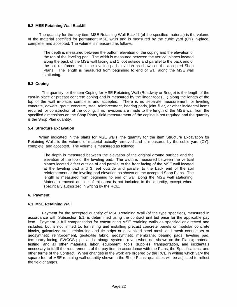
5.2 MSE Retaining Wall Backfill The quantity for the pay item MSE Retaining Wall Backfill (of the specified material) is the volume of the material specified for permanent MSE walls and is measured by the cubic yard (CY) in-place, complete, and accepted. The volume is measured as follows:
The depth is measured between the bottom elevation of the coping and the elevation of the top of the leveling pad. The width is measured between the vertical planes located along the back of the MSE wall facing and 1 foot outside and parallel to the back end of the soil reinforcement at the leveling pad elevation as shown on the accepted Shop Plans. The length is measured from beginning to end of wall along the MSE wall stationing.
5.3 Coping The quantity for the item Coping for MSE Retaining Wall (Roadway or Bridge) is the length of the cast-in-place or precast concrete coping and is measured by the linear foot (LF) along the length of the top of the wall in-place, complete, and accepted. There is no separate measurement for leveling concrete, dowels, grout, concrete, steel reinforcement, bearing pads, joint filler, or other incidental items required for construction of the coping. If no revisions are made to the length of the MSE wall from the specified dimensions on the Shop Plans, field measurement of the coping is not required and the quantity is the Shop Plan quantity.
5.4 Structure Excavation When indicated in the plans for MSE walls, the quantity for the item Structure Excavation for Retaining Walls is the volume of material actually removed and is measured by the cubic yard (CY), complete, and accepted. The volume is measured as follows:
The depth is measured between the elevation of the original ground surface and the elevation of the top of the leveling pad. The width is measured between the vertical planes located 2 feet outside of and parallel to the front facing of the MSE wall located at the leveling pad and 3 feet outside and parallel to the back end of the soil reinforcement at the leveling pad elevation as shown on the accepted Shop Plans. The length is measured from beginning to end of wall along the MSE wall stationing. Material removed outside of this area is not included in the quantity, except where specifically authorized in writing by the RCE.
6. Payment
6.1 MSE Retaining Wall
Payment for the accepted quantity of MSE Retaining Wall (of the type specified), measured in accordance with Subsection 5.1, is determined using the contract unit bid price for the applicable pay item. Payment is full compensation for constructing MSE retaining walls as specified or directed and includes, but is not limited to, furnishing and installing precast concrete panels or modular concrete blocks, galvanized steel reinforcing and tie strips or galvanized steel mesh and mesh connectors or geosynthetic reinforcement, geotextile fabric, geosynthetic membrane, bearing pads, leveling pad, temporary facing, SWCGS pipe, and drainage systems (even when not shown on the Plans); material testing; and all other materials, labor, equipment, tools, supplies, transportation, and incidentals necessary to fulfill the requirements of the pay item in accordance with the Plans, the Specifications, and other terms of the Contract. When changes in the work are ordered by the RCE in writing which vary the square foot of MSE retaining wall quantity shown in the Shop Plans, quantities will be adjusted to reflect the field changes.
Page 23
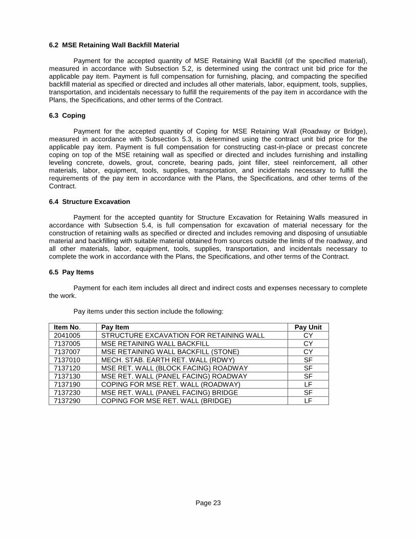
6.2 MSE Retaining Wall Backfill Material
Payment for the accepted quantity of MSE Retaining Wall Backfill (of the specified material), measured in accordance with Subsection 5.2, is determined using the contract unit bid price for the applicable pay item. Payment is full compensation for furnishing, placing, and compacting the specified backfill material as specified or directed and includes all other materials, labor, equipment, tools, supplies, transportation, and incidentals necessary to fulfill the requirements of the pay item in accordance with the Plans, the Specifications, and other terms of the Contract. 6.3 Coping
Payment for the accepted quantity of Coping for MSE Retaining Wall (Roadway or Bridge), measured in accordance with Subsection 5.3, is determined using the contract unit bid price for the applicable pay item. Payment is full compensation for constructing cast-in-place or precast concrete coping on top of the MSE retaining wall as specified or directed and includes furnishing and installing leveling concrete, dowels, grout, concrete, bearing pads, joint filler, steel reinforcement, all other materials, labor, equipment, tools, supplies, transportation, and incidentals necessary to fulfill the requirements of the pay item in accordance with the Plans, the Specifications, and other terms of the Contract. 6.4 Structure Excavation
Payment for the accepted quantity for Structure Excavation for Retaining Walls measured in accordance with Subsection 5.4, is full compensation for excavation of material necessary for the construction of retaining walls as specified or directed and includes removing and disposing of unsutiable material and backfilling with suitable material obtained from sources outside the limits of the roadway, and all other materials, labor, equipment, tools, supplies, transportation, and incidentals necessary to complete the work in accordance with the Plans, the Specifications, and other terms of the Contract.
6.5 Pay Items
Payment for each item includes all direct and indirect costs and expenses necessary to complete
the work. Pay items under this section include the following:
Item No. Pay Item Pay Unit 2041005 STRUCTURE EXCAVATION FOR RETAINING WALL CY 7137005 MSE RETAINING WALL BACKFILL CY 7137007 MSE RETAINING WALL BACKFILL (STONE) CY 7137010 MECH. STAB. EARTH RET. WALL (RDWY) SF 7137120 MSE RET. WALL (BLOCK FACING) ROADWAY SF 7137130 MSE RET. WALL (PANEL FACING) ROADWAY SF 7137190 COPING FOR MSE RET. WALL (ROADWAY) LF 7137230 MSE RET. WALL (PANEL FACING) BRIDGE SF 7137290 COPING FOR MSE RET. WALL (BRIDGE) LF