Mechanical)Design)Document) - INAF - OA-Breracanestrari/pubblicazioni/pubbl58.pdf · ASTRI -...
26
ASTRI - Astrofisica con Specchi a Tecnologia Replicante Italiana Code: ASTRI-TTT-PPP-XXX-NNN Issue: 1 DATE 09-11-2012 Page: 1 All information contained in this document is property of INAF. All rights reserved. Mechanical Design Document Prepared by: Name: Rodolfo Canestrari Signature: Date: 09112012 Enrico Giro 09112012 Reviewed by: Name: Signature: Date: Approved by: Name: Mauro Fiorini Signature: Date: Luca Stringhetti Enrico Giro
Transcript of Mechanical)Design)Document) - INAF - OA-Breracanestrari/pubblicazioni/pubbl58.pdf · ASTRI -...

ASTRI - Astrofisica con Specchi a Tecnologia Replicante Italiana
Code: ASTRI-TTT-PPP-XXX-NNN Issue: 1 DATE 09-11-2012 Page: 1
All information contained in this document is property of INAF. All rights reserved.
Mechanical Design Document
Prepared by: Name: Rodolfo Canestrari Signature: Date: 09-‐11-‐2012
Enrico Giro 09-‐11-‐2012
Reviewed by: Name: Signature: Date: Approved by: Name: Mauro Fiorini Signature: Date:
Luca Stringhetti Enrico Giro

ASTRI - Astrofisica con Specchi a Tecnologia Replicante Italiana
Code: ASTRI-TTT-PPP-XXX-NNN Issue: 1 DATE 09-11-2012 Page: 2
All information contained in this document is property of INAF. All rights reserved.
TABLE OF CONTENTS
DISTRIBUTION LIST ................................................................................................................................... 3
DOCUMENT HISTORY ................................................................................................................................ 4
LIST OF ACRONYMS .................................................................................................................................. 5
APPLICABLE DOCUMENTS ......................................................................................................................... 5
REFERENCE DOCUMENTS .......................................................................................................................... 5
1. INTRODUCTION ................................................................................................................................. 7
2. GENERAL DESCRIPTION ..................................................................................................................... 8
3. THE STRUCTURAL DESIGN ................................................................................................................. 10
3.1 The quadrupode mast ................................................................................................................... 10
3.2 The M1 dish ................................................................................................................................... 11
3.3 The M2 dish ................................................................................................................................... 12
3.4 The global model of the telescope ................................................................................................ 12 3.4.1 Pointing performances ........................................................................................................ 15 3.4.2 Seismic effects .................................................................................................................... 15 3.4.1 Preliminary mass budget .................................................................................................... 17
4. THE MECHANICAL SUBSYSTEMS ....................................................................................................... 18
4.1 The Azimuth subsystems ............................................................................................................... 19
4.2 The Elevation subsystems ............................................................................................................. 20
5. THE MIRRORS SUPPORTING AND ALIGNMENT SYSTEMS ................................................................... 23
5.1 Primary mirror segments ............................................................................................................... 23
5.2 Secondary mirror ........................................................................................................................... 25

ASTRI - Astrofisica con Specchi a Tecnologia Replicante Italiana
Code: ASTRI-TTT-PPP-XXX-NNN Issue: 1 DATE 09-11-2012 Page: 3
All information contained in this document is property of INAF. All rights reserved.
DISTRIBUTION LIST
ASTRI Project Office astri-‐[email protected]
MIUR Committee

ASTRI - Astrofisica con Specchi a Tecnologia Replicante Italiana
Code: ASTRI-TTT-PPP-XXX-NNN Issue: 1 DATE 09-11-2012 Page: 4
All information contained in this document is property of INAF. All rights reserved.
DOCUMENT HISTORY
Version Date Modification
1.0 09-‐11-‐2012 First version

ASTRI - Astrofisica con Specchi a Tecnologia Replicante Italiana
Code: ASTRI-TTT-PPP-XXX-NNN Issue: 1 DATE 09-11-2012 Page: 5
All information contained in this document is property of INAF. All rights reserved.
LIST OF ACRONYMS
ASTRI Astrofisica con Specchi a Tecnologia Replicante Italiana
CFRP Carbon Fiber Reinforced Plastic
FEA Finite Element Analyses
FEM Finite Element Model
INAF Istituto Nazionale di AstroFisica
M1 Primary mirror
M2 Secondary mirror
PDR Preliminary Design Review
PID Proportional Integrative Derivative
PSF Point Spread Function
SOW Statement of the Work
TBW To Be Written
wrt with respect to
APPLICABLE DOCUMENTS
[AD1] ASTRI-‐SOW-‐OAB-‐3100-‐002 “Statement of the Work for the engineering structural design of a dual-‐mirror Cherenkov telescope prototype for the ASTRI project: the Small Size Telescope of the CTA observatory”
[AD2] ASTRI-‐SOW-‐OAB-‐3100-‐003 “Statement of the Work for the engineering design of mechanical subsystems for a dual-‐mirror Cherenkov telescope prototype for the ASTRI project: the Small Size Telescope of the CTA observatory”
[AD3] ASTRI-‐IR-‐OAB-‐3100-‐009 “The optical layout of the ASTRI prototype: 4 meter Schwarzschild-‐Couder Cherenkov telescope for CTA with 10° of field of view”
[AD4] ASTRI-‐SPEC-‐OAB-‐3100-‐002 “Error Budget Tree for the ASTRI prototype: structure and mirrors”
[AD5] ASTRI-‐SPEC-‐OAB-‐3100-‐003 “ASTRI SST design loads”
REFERENCE DOCUMENTS
[RD1] ASTRI-‐ES-‐BCV-‐3110-‐012 “Analyses supporting the preliminary design of ASTRI structures”

ASTRI - Astrofisica con Specchi a Tecnologia Replicante Italiana
Code: ASTRI-TTT-PPP-XXX-NNN Issue: 1 DATE 09-11-2012 Page: 6
All information contained in this document is property of INAF. All rights reserved.
[RD2] ASTRI-‐ES-‐TOM-‐3110-‐013 “CTA-‐DM Preliminary study” [RD3] ASTRI-‐ES-‐TOM-‐3110-‐024 “CTA-‐DM Executive design” [RD4] ASTRI-‐ES-‐BCV-‐3110-‐008 “Azioni per dimensionamento organi meccanici”

ASTRI - Astrofisica con Specchi a Tecnologia Replicante Italiana
Code: ASTRI-TTT-PPP-XXX-NNN Issue: 1 DATE 09-11-2012 Page: 7
All information contained in this document is property of INAF. All rights reserved.
1. INTRODUCTION This document aims to give a comprehensive description of the ASTRI telescope Mechanical Design. This design follows the requests given in the SOWs issued by INAF at the beginning of the project activities [AD1] and [AD2] and eventual latest updates/changes.
In particular it will be described the telescope layout and performances from the structural point of view having as a reference the work provided by BCV Progetti s.r.l. at the PDR [RD1] and latest developments presented at the monthly meetings.
The engineering solutions concerning mainly the telescope drive, bearing and safety systems are also treated in this document in accordance with the work provided by Tomelleri s.r.l. at the PDR [RD2] and latest developments presented at the monthly meetings with particular emphasis to the draft document of the execute design [RD3].

ASTRI - Astrofisica con Specchi a Tecnologia Replicante Italiana
Code: ASTRI-TTT-PPP-XXX-NNN Issue: 1 DATE 09-11-2012 Page: 8
All information contained in this document is property of INAF. All rights reserved.
2. GENERAL DESCRIPTION
The telescope is presented in Figure 2.1. The major parts are the mount that is composed by the base, the tower and the fork; and the optical supporting structure that is composed by the primary mirror (dish and mirrors) the mast, the secondary mirror (dish and mirror) and the ballasts.
The mounting of the telescope is of the alt-‐azimuthal type. The fork supports the telescope, hosts the elevation subsystems and connects the telescope with the column. This hosts the azimuth driving and bearing systems. The azimuth axis will admit a useful rotation range between -‐270° and +270° over a total run of 550°. In a similar way, the elevation axis admits a useful movement range between -‐5° and +95° over a total run of 110°.
The optical supporting structure has a thick ribbed plate to support the 18 mirror segments. This plate (the M1 dish) is connected with the mast and, to balance the torque due to the overhang of the telescope structure, with two long arms supporting the counterweights. The mast is a slim quadrupode with an eccentric symmetry and some radial bracings to improve the bending stiffness. A central tube links the bracings with the main legs; it improves the torsional stiffness and provides the support for the detector. Finally, on top of the mast a lattice of tubes forms the dish for the secondary mirror. This also provides the connections with the alignment devices of the secondary mirrors and to the shield against the stray light.
Figure 2.1 General view of the ASTRI telescope structure.

ASTRI - Astrofisica con Specchi a Tecnologia Replicante Italiana
Code: ASTRI-TTT-PPP-XXX-NNN Issue: 1 DATE 09-11-2012 Page: 9
All information contained in this document is property of INAF. All rights reserved.
The telescope will be made in stainless steel material because of a number of advantages compared to other structural materials such as Aluminum or CFRP. They are mainly: cost wrt CFRP, thermo-‐mechanical performances (stiffness vs specific weight and CTE) wrt Aluminum. Also manufacturing processes of steel are simpler than Aluminum ones (i.e. soldering).
The dimensions of the telescope are driven by the optical design described in [AD3], and in particular the relative distances between the different optical elements (primary and secondary mirrors and the focal surface). Meanwhile, the dimensioning of the structural components is imposed both by the tolerances reported in [AD4] and by the loads reported in [AD5].

ASTRI - Astrofisica con Specchi a Tecnologia Replicante Italiana
Code: ASTRI-TTT-PPP-XXX-NNN Issue: 1 DATE 09-11-2012 Page: 10
All information contained in this document is property of INAF. All rights reserved.
3. THE STRUCTURAL DESIGN In this chapter we present the structural design of the telescope at the state of the art. The aim is to give a global view of the telescope structure for an easy understanding of its main parts. Detailed descriptions of the work performed, parameters investigated and performances are not reported here, however they can be found in a variety of documents on the ASTRI repository.
The approach used in designing the telescope structures has followed the path hereafter reported. For each main part of the telescope (i.e. the mast and the M1 dish) a variety of designs have been individually proposed, sketched and evaluated. Through a trade-‐off activity (typically between performances, mass, easiness of production and assembling) one option is selected for advancing the design. At this stage, each part has been considered as constrained to infinitely stiff points. Ones the main parts are selected a simplified global model of the entire telescope is modeled and evaluated. In order to access the integrated performances of the selected solutions, only a limited subset of loading conditions are considered [RD1]. The outcomes of this phase are used to highlight the weak points of the actual design and to allow its refinement to improve the performances and meet the project requirements. Moreover, the forces acting of the mechanical components such as the bearings, the drives, the gears and other devices are evaluated for the proper sizing the mentioned components [RD4]. Finally, the very detailed integrated model of the telescope is generated. This model now takes into account also the performance specifications of the mechanical components, the mirrors and other devices eventually on board the telescope (shields, scientific detector, etc.). The full set of loading cases is applied and the comprehensive behavior of the telescope is asserted.
All the telescope structural components are modeled and evaluated by means of finite elements numerical approach (FEM and FEA).
3.1 The quadrupode mast
The configuration emerging from the trade-‐off study is presented in Figure 3.1. The mast is composed by an eccentric quadrupode with a radial bracing system connecting: the M2 platform, the central tube and the quadrupode legs. This solution shows increased performances in comparison with simpler configurations. In particular, the quadrupode conferees the adequate rigidity against later deformations and, being eccentric, it gives enhanced performances along the elevation axis. Finally, the central tube increases the torsional stiffness. It also achieves a certain amount of saving in obstruction of off-‐axis rays. Moreover, the construction and assembly of the complete system seems quite simplified, for instance with respect to the use of pre-‐tensioned ropes. As last but not least point, this configuration allow some freedom in adjusting the relative distances between the optical components (namely the M1, M2 and detector) in case of slight modifications of the optical design emerging from in-‐field tests.
The modeled items have an estimated mass of 1821 kg. The camera has been modeled as a concentrated mass, while M2 and its supporting system have been modeled as equivalent bodies of the estimated mass.
The thermo-‐elastic behavior has been also investigated in order to check the impact on the optical performances and pointing errors of the telescope. Thermal gradients have been imposed along the optical axis, the elevation and cross-‐elevation axes. Negligible effects

ASTRI - Astrofisica con Specchi a Tecnologia Replicante Italiana
Code: ASTRI-TTT-PPP-XXX-NNN Issue: 1 DATE 09-11-2012 Page: 11
All information contained in this document is property of INAF. All rights reserved.
are observed in the optical performances, while having modest contributions to the pointing.
Figure 3.1 (left) FEM of the mast structure. (right) Evaluation of the Eigen-‐modes.
3.2 The M1 dish
The dish has a ribbed plate structure in a flat geometry; it is open at the bottom side with a box section beam in correspondence of the elevation axis. The plate is composed of two asymmetric halves connected along the middle plane by means of plugs. The connection line is orthogonal respect to the elevation plane. Concerning the back side of the dish, the upper half hosts the connection with the linear actuator of the elevation drive system, while the other one has the interfaces with the two arms of the fork where the elevation axis lies. In the front side, the connections with each mirror segment are hosted. A triangular frame, each one having three separated contact points, individually supports the mirrors: to the mirror side through actuators; while to the dish side by means of spacers (they also take into account for the gross curvature of the primary mirror). This solution seems to be considerably stiffer wrt a solution with a single leg connection. Also connected to the dish are the counterweights supporting arms. The mast quadrupode subsystem is connected with the dish thorough cantilevered beams; this solution has been adopted in order to save mass while keeping the necessary rigidity. Moreover, additional light weighting solutions will be undertaken. The modeled dish has an estimated mass of 5200 kg. Figure 3.2 shows the FEM of the M1 dish together with the mast structure on top of it.

ASTRI - Astrofisica con Specchi a Tecnologia Replicante Italiana
Code: ASTRI-TTT-PPP-XXX-NNN Issue: 1 DATE 09-11-2012 Page: 12
All information contained in this document is property of INAF. All rights reserved.
Figure 3.2 Combined FEM of the M1 dish and the mast structures.
3.3 The M2 dish
Beams arranged in a lattice structure compose the supporting structure of the secondary mirror. It allows the connections with the three actuators of the mirror and the lateral restrains used to keep the in-‐plane position of the mirror.
This structure also hosts the interface with the supporting structure of the stray-‐light baffle device.
Figure 3.3 Secondary mirror supporting structure FEM and 3D CAD view including the
entire M2 subsystem.
3.4 The global model of the telescope
The selected solutions presented above have been assembled together to form the global model of the telescope. Preliminary 3D CAD views have been generated and some quoted sections drawing of the telescope derived. They are reported in Figure 3.4. Some engineering solutions under design are also visible.

ASTRI - Astrofisica con Specchi a Tecnologia Replicante Italiana
Code: ASTRI-TTT-PPP-XXX-NNN Issue: 1 DATE 09-11-2012 Page: 13
All information contained in this document is property of INAF. All rights reserved.
Figure 3.4 Preliminary 3D CAD model and sections drawing of the telescope.
A FEM of the entire telescope system has been generated, too. It comprises all the telescope structural parts and components such as the base, the tower, the fork, the primary mirror ensemble (dish, mirror segments and supporting/alignment frames), the quadrupode mast, the secondary mirror ensemble (dish, monolithic mirror,

ASTRI - Astrofisica con Specchi a Tecnologia Replicante Italiana
Code: ASTRI-TTT-PPP-XXX-NNN Issue: 1 DATE 09-11-2012 Page: 14
All information contained in this document is property of INAF. All rights reserved.
supporting/alignment devices and stray-‐light baffle) and the ballasts. The model shown in Figure 3.5 and considers also the bearings and driving systems. The evaluation of the Eigen-‐frequencies of the telescope returns in a nearly constant behavior wrt the azimuthal position and showing values well above the project specifications. In the worst case scenario (i.e. horizon pointing), the first two modes are higher than 4 Hz and being respectively the oscillations around the azimuth and elevation axes. As a reference, we report in Figure 3.6 the first four modes.
Figure 3.5: FEM of the entire telescope system.
Figure 3.6 Evaluation of the Eigen-‐frequencies of the ASTRI telescope.

ASTRI - Astrofisica con Specchi a Tecnologia Replicante Italiana
Code: ASTRI-TTT-PPP-XXX-NNN Issue: 1 DATE 09-11-2012 Page: 15
All information contained in this document is property of INAF. All rights reserved.
The impact of the structural deformations into the optical performances of the telescope has been also evaluated. Relative displacements and tilts between the optical elements caused by a variety of loadings (i.e. gravity, wind, thermal) have been considered. They return to have a negligible impact on the PSF; a worsening of the order of 1% is calculated.
3.4.1 Pointing performances
Pointing is affected by several error sources due to the structural behavior. Among them we have encoders reading, gravity, wind and thermal errors. They can be grouped into two main categories and treated separately: deterministic and random errors.
Deterministic errors can be corrected by applying proper offsets in case of encoders reading and static wind (sail effect) errors also, structural flexure modeling (e.g. TPOINT) can be used to compensate gravity errors.
Typical random errors are those generated by wind gusts and thermal gradients. Wind gusts can be neglected because even if they affect in a substantial way the single detected event, the Cherenkov observation is composed by many of those (hundreds or thousands). On the contrary, the errors induced by thermal effects have to be taken into account. But they could be treated as deterministic ones if a reliable thermal model of the telescope is developed and applied during pointing.
The telescope performances have been evaluated for all these contributions and the results from the worst case scenarios are presented in Table 3.1.
Error source Elevation pointing error
[arcsec]
Azimuthal pointing error
[arcsec]
Encoders reading 47.6 0
Gravity 36.9 2.5
Wind (static) 15.9 11.6
Wind (gusts) 7.8 0
Thermal (gradients) 31.9 25.5
Thermal (bulk) 1.3 0.6
Table 3.1 Summary of the error contributions to the pointing.
3.4.2 Seismic effects
To evaluate the response of the telescope to seismic loads, both modal and response spectrum analyses have been done. SRSS rules on single seismic effects along (x, y, z) have been used to take into account the possibility of contemporaneous earthquakes in different directions. Two different conditions have been studied in accordance with [AD5]. They simulate: one site with a very low seismic hazard (Namibia/South-‐Africa –like) and another one with a high seismic hazard (Argentina –like). The response spectra applied to

ASTRI - Astrofisica con Specchi a Tecnologia Replicante Italiana
Code: ASTRI-TTT-PPP-XXX-NNN Issue: 1 DATE 09-11-2012 Page: 16
All information contained in this document is property of INAF. All rights reserved.
the telescope structure are shown in Figure 3.7, the analyses confirm the factor four between the two loading conditions (see Figure 3.8). However, the telescope does not suffer any disruptive force. Detailed stress checks are anyway under computation.
Figure 3.7 Response spectra for the two sites analyzed.
Figure 3.8 Distribution of the accelerations on the telescope structure. For both the loading conditions we report, as example, the preliminary values along the elevation axis (top) and
along the optical axis (bottom).
ASTRI - Astrofisica con Specchi a Tecnologia Replicante Italiana
Code: ASTRI-TTT-PPP-XXX-NNN Issue: 1 DATE 09-11-2012 Page: 17
All information contained in this document is property of INAF. All rights reserved.
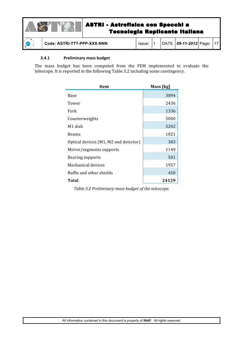
3.4.1 Preliminary mass budget
The mass budget has been computed from the FEM implemented to evaluate the telescope. It is reported in the following Table 3.2 including some contingency.
Item Mass [kg]
Base 3894
Tower 2436
Fork 1336
Counterweights 5000
M1 dish 5202
Beams 1821
Optical devices (M1, M2 and detector) 383
Mirror/segments supports 1149
Bearing supports 501
Mechanical devices 1957
Baffle and other shields 450
Total 24129
Table 3.2 Preliminary mass budget of the telescope.

ASTRI - Astrofisica con Specchi a Tecnologia Replicante Italiana
Code: ASTRI-TTT-PPP-XXX-NNN Issue: 1 DATE 09-11-2012 Page: 18
All information contained in this document is property of INAF. All rights reserved.
4. THE MECHANICAL SUBSYSTEMS
Three major parts compose the pillar: the base, the tower and the fork. It has the main purpose to support and move the telescope main structure (i.e. the M1 dish, the mast and the M2 dish) with the required performances as velocity, acceleration and position accuracy, under the defined loads and environmental conditions.
Initially, an innovative solution for the mounting system of the telescope has been proposed and studied. The aim was to end up with a low cost, low weight and easy to assembly telescope. The “cardanic mounting” concept is based on the use of a common driving and bearing systems to achieve the full-‐sky orientation of the telescope structure. It makes use on two identical linear actuators; they are linked to the back of the M1 dish forming a triangle with the gimbal (or cardanic joint: a single mechanical joint having 2-‐degree of freedom). The telescope might be simply placed on top of a reinforced concrete column. Unfortunately, a major limitation was found in the minimum Eigen-‐frequency of the telescope. It drops to a very low value in correspondence to the horizontal pointing, making the safety of the structure a crucial point.
Therefore, the classical alt-‐azimuth mounting has been preferred; several solutions have been investigated. The sketch in Figure 4.1 shows the preferred solution that is described in the following.
Figure 4.1 General description of the telescope's mechanical subsystems.

ASTRI - Astrofisica con Specchi a Tecnologia Replicante Italiana
Code: ASTRI-TTT-PPP-XXX-NNN Issue: 1 DATE 09-11-2012 Page: 19
All information contained in this document is property of INAF. All rights reserved.
4.1 The Azimuth subsystems
The subsystem for the azimuth movement is composed by the base and the tower where, respectively, are located the driving and the bearing systems.
The base is a large box fixed on its lower part to the foundation; it hosts the complete driving system for the azimuth axis as shown Figure 4.2. The following devices compose it. There are two driving chains in a master-‐slave configuration. Each one is composed by one commercial epicycloids gearbox and one suitable designed gearbox. The pinions link the gearboxes to brushless servomotors. In this solution the two motors can work with a preloaded differential torque that gives a number of advantages. Among them we recall: higher torque and stiffness capability due to the sum of the two gears chains; less preloading torque between the two pinions; minimized backlash between the pinions and rim gear in all the positioning operations. Moreover, their maintenance is very simple because easily accessible. For safety reasons both motors are endowed by a braking system that locks the axis without power supply. In addition, one of the two driving chains is equipped with a couple of emergency driving systems: a teethed clutch can be engaged by powering on a 24 V DC motor and an irreversible gearbox; and a shaft for the manual driving, it is accessible by demounting a safety cover endowed by the proper electro switch. Both the emergency systems are decoupled in operational conditions.
Figure 4.2 (left) Cross-‐section view of the driving system of the azimuth axis. (right) 3D CAD
view of the telescope's base.
The tower is composed by two concentric large tubes at the ends of which two ball bearings are located (see the left panel in Figure 4.3). An adjustable spacer axially preloads them; this has the purpose to avoid the axial backlash and to increase the axial stiffness. The lower bearing and the external tube supports weight of the entire telescope, meanwhile the inner tube (acting as the azimuth shaft) and the upper bearing transfers the azimuth movement to the telescope. The positioning is retrieved by means of an absolute angular transducer placed at the lower end of the azimuth shaft, close to the driving system. The full rotation stroke of the azimuth axis reaches 540°, this range is software limited by reading the azimuth encoder. However, since the stroke allows more than one rotation, a special system is designed to recover the information about the direction of the motion. There is a roller lever yoke that constantly maintains the contact with the flange of the bottom bearing. The flange is equipped with special references that

ASTRI - Astrofisica con Specchi a Tecnologia Replicante Italiana
Code: ASTRI-TTT-PPP-XXX-NNN Issue: 1 DATE 09-11-2012 Page: 20
All information contained in this document is property of INAF. All rights reserved.
allow to recognize the main rotation from the second one, and therefore to commutate the two electromechanical limit switches of the main direction with the two of the opposite one. This solution is sketched in the right panel of Figure 4.3.
Figure 4.3 (left) Cross-‐section view of the tower. (right) Flange of the bottom bearing equipped with the devices devoted to the motion direction recognition.
Finally, an electromechanical stow pin is foreseen at the parking position. This device mainly consists of a pin axially guided into a cylindrical bush; it is moved by a motor-‐driven screw with an irreversible gearbox. Two electro switches detect the stroke of the pin. It is designed by taking into account the maximum loads and torques on the axis acting during the survival conditions. In this way, it will allow to lock the telescope in position up to the worst load conditions.
4.2 The Elevation subsystems
The subsystem for the elevation movement is mounted on the fork. The main components are the bearings, the driving and the locking systems.
The motion is accomplished by means of a linear actuator. It is composed by a fixed preloaded ball screw (the shaft), a rotating preloaded nut, the gearboxes and the motor. The ball screw is moved up and down by the rotating nut, which is driven by the motorized gearbox set. There are also a couple of joints: one is screwed to the M1 dish and the other one to the fork. This last one also supports the body of the actuator, the gearbox and the motor. Both joints are realized by means of preloaded tapered roller bearings and have their axes parallel to the elevation axis. In the same way in which the azimuth axis is designed, for safety reasons, the motor is endowed by a braking system that locks the axis without power supply. In addition, a couple of emergency driving systems are also available: a teethed clutch can be engaged by powering on a 24 V DC motor and an

ASTRI - Astrofisica con Specchi a Tecnologia Replicante Italiana
Code: ASTRI-TTT-PPP-XXX-NNN Issue: 1 DATE 09-11-2012 Page: 21
All information contained in this document is property of INAF. All rights reserved.
irreversible gearbox; and a shaft for the manual driving, it is accessible by demounting a safety cover endowed by the proper electro switch. Both the emergency systems are decoupled in operational conditions. Figure 4.4 shows the driving system described above.
Figure 4.4 (left) 3D CAD view of the elevation subsystems: bearings, driving and locking devices. (center, right) Cross-‐section views of the linear actuator and its bearings.
The elevation axis lies on the arms of the fork. The shaft is divided into two parts at the end of the arms where two identical bearing system units are located. Each one connects and supports the telescope thought the M1 dish. Each bearing unit (see the left panel in Figure 4.5) is composed by eight tapered roller bearings; they are axially preloaded by means of suitable threaded bushes in order to minimize the backlash. A rotating support is screwed to the backside of the M1 dish. One of the two bearing units hosts the absolute angular encoder to retrieve the positioning.
The elevation axis admits a total stroke included between -‐5° up to +95°; this range is software limited by reading the elevation encoder. Additional angular motion is permitted for safety reasons with two electromechanical switches that limit the run in case of software failure. This solution is sketched in the right panel of Figure 4.5. Bumpers are also envisaged.
Similarly to the azimuth axis, an electromechanical stow pin is foreseen. This device will allow locking the telescope in two positions: horizontal (the parking position) and zenith pointing.

ASTRI - Astrofisica con Specchi a Tecnologia Replicante Italiana
Code: ASTRI-TTT-PPP-XXX-NNN Issue: 1 DATE 09-11-2012 Page: 22
All information contained in this document is property of INAF. All rights reserved.
Figure 4.5 (left) Cross-‐section view of the elevation bearing system located at the end of the fork arm. (right) 3D CAD view of the limit switches for the elevation axis.

ASTRI - Astrofisica con Specchi a Tecnologia Replicante Italiana
Code: ASTRI-TTT-PPP-XXX-NNN Issue: 1 DATE 09-11-2012 Page: 23
All information contained in this document is property of INAF. All rights reserved.
5. THE MIRRORS SUPPORTING AND ALIGNMENT SYSTEMS
5.1 Primary mirror segments
As described in [RD3] the support and tilting system for the M1 segments has been designed to actively align the primary mirrors in a way to maintain the PSF specification of the telescope. During pointing and tracking operations flexures and misalignments due to gravity, wind and temperature are well inside PSF requirements and they can in principle only affect pointing tolerances. For this reason the actuation of mirrors is performed in open loop mode during scientific acquisition.
Each segment of the main mirror is supported in isostatic way by one fixed support (axial fixed point), two active supports (axial actuators) placed at suitable distance among them, and a tangential rod, obtaining the required six constraints to the segment. In this way it is possible to tune the two direction tilts of the panel, moving the optical axis in the desired direction. Figure 5.1 shows this system.
Figure 5.1 Support of the segment with the actuation system.
The actuators used are designed with an eccentric shaft coupled with a step motor. A short piston rod is mounted to avoid lateral loads on the actuators. The system is designed to mount and demount each segment together its structure without involving the others (see below).
The correct positioning of the actuators is assured by a zeroing procedure to be performed at start-‐up that calibrates the incremental encoders applied to the actuators.
Main characteristics of the system are reported in Table 5.1.
To install and remove the single panels in a safe a fast way a tool with suitable pins has been designed. In Figure 5.2 a schematic representation shows how it works.

ASTRI - Astrofisica con Specchi a Tecnologia Replicante Italiana
Code: ASTRI-TTT-PPP-XXX-NNN Issue: 1 DATE 09-11-2012 Page: 24
All information contained in this document is property of INAF. All rights reserved.
Code Description Value
R70 Axial actuator stroke >+ 5 mm
R71 Angular stroke around x and y > ± 0.5°
R72 Angular induce rotation around z < ± 4’
R73 Maximum axial velocity >0.5 mm/s
R74 Maximum x and y tolerance to adjacent <± 2 mm
R75 Axial accuracy rms <± 0.01 mm
R76 Axial resolution <0.005 mm
R77 Angular accuracy around x and y <± 30”
R78 Actuator axial movement positioning Unidirectional
R79 Maximum operational axial force 336 N
R80 Maximum survival axial force 1020 N
R81 Axial actuator stiffness 30 N/micron
R82 Maximum operational force on the lateral fixed point 1020 N
R83 Stiffness of the lateral fixed point 20 N/micron
Table 5.1 Main characteristics on actuation of M1 segments.
Figure 5.2 Schematic representation of the handling tool used to mount panels.

ASTRI - Astrofisica con Specchi a Tecnologia Replicante Italiana
Code: ASTRI-TTT-PPP-XXX-NNN Issue: 1 DATE 09-11-2012 Page: 25
All information contained in this document is property of INAF. All rights reserved.
5.2 Secondary mirror
The secondary mirror supports is designed on three actuators permitting tilts and piston necessary to align the mirror inside the optical system. To better share loads and weight the actuators are connected to the mirror by means of three whiffletrees as shown in Figure 5.3.
Figure 5.3 The secondary support system shown from the rear of the mirror.
Three lateral constraints with high axial stiffness assure to support lateral components, locking the three remaining degree of freedom and supporting the mirror in an isostatic way. A rotating nut driven by a stepper motor composes the single actuator permitting the actuation. Three absolute encoders track the position of the actuators.
In the Table 5.2 the main characteristics of the actuation is shown.

ASTRI - Astrofisica con Specchi a Tecnologia Replicante Italiana
Code: ASTRI-TTT-PPP-XXX-NNN Issue: 1 DATE 09-11-2012 Page: 26
All information contained in this document is property of INAF. All rights reserved.
Code Description Value
R90 Maximum operational axial push force on rod 725 N
R91 Maximum operational axial pull force on rod 900 N
R92 Maximum survival push force on the actuator 1960 N
R93 Maximum survival pull force on the actuator 2400 N
R94 Axial stroke ± 7.50 mm
R95 Angular stroke ± 0.35°
R96 Resolution of the actuator 0.01 mm
R97 Accuracy of the actuator RMS ± 0.02 mm
R98 Velocity of the actuator 0.75 mm/s
R99 Axial actuator stiffness 30 N/micron
R100 Angular accuracy around x and y <± 10’
R101 Lateral adjusting of the position ± 3 mm
R102 Axial adjusting of the position ± 4 mm
R103 Max. survival load on lateral fixed points 3050 N
R104 Max. operational load on lateral fixed points 3050 N
R105 Stiffness of the lateral fixed points 40 N/micron
R106 Actuator movement for mirror positioning unidirectional
Table 5.2 Main characteristics on actuation of M2 mirror.