Mechanical vibration — Evaluation of machine vibration by … ISO... · 2019-05-15 · ISO...
28
BS ISO 10816-4:2009 ICS 17.160; 27.040 NO COPYING WITHOUT BSI PERMISSION EXCEPT AS PERMITTED BY COPYRIGHT LAW BRITISH STANDARD Mechanical vibration — Evaluation of machine vibration by measurements on non- rotating parts Part 4: Gas turbine sets with fluid-film bearings
Transcript of Mechanical vibration — Evaluation of machine vibration by … ISO... · 2019-05-15 · ISO...

BS ISO10816-4:2009
ICS 17.160; 27.040
NO COPYING WITHOUT BSI PERMISSION EXCEPT AS PERMITTED BY COPYRIGHT LAW
BRITISH STANDARD
Mechanical vibration— Evaluation ofmachine vibration bymeasurements on non-rotating partsPart 4: Gas turbine sets with fluid-filmbearings

This British Standardwas published underthe authority of theStandards Policy andStrategy Committee on 30November 2009© BSI 2009
ISBN 978 0 580 64809 0
Amendments/corrigenda issued since publication
Date Comments
BS ISO 10816-4:2009
National foreword
This British Standard is the UK implementation of ISO 10816-4:2009. Itsupersedes BS 7854-4:1998 which is withdrawn.The UK participation in its preparation was entrusted to TechnicalCommittee GME/21/5, Vibration of machines.A list of organizations represented on this committee can be obtained onrequest to its secretary.This publication does not purport to include all the necessary provisionsof a contract. Users are responsible for its correct application.Compliance with a British Standard cannot confer immunityfrom legal obligations.

BS ISO 10816-4:2009
Reference numberISO 10816-4:2009(E)
© ISO 2009
INTERNATIONAL STANDARD
ISO10816-4
Second edition2009-10-01
Mechanical vibration — Evaluation of machine vibration by measurements on non-rotating parts — Part 4: Gas turbine sets with fluid-film bearings
Vibrations mécaniques — Évaluation des vibrations des machines par mesurages sur les parties non tournantes —
Partie 4: Turbines à gaz à paliers à film fluide

BS ISO 10816-4:2009ISO 10816-4:2009(E)
PDF disclaimer This PDF file may contain embedded typefaces. In accordance with Adobe's licensing policy, this file may be printed or viewed but shall not be edited unless the typefaces which are embedded are licensed to and installed on the computer performing the editing. In downloading this file, parties accept therein the respons bility of not infringing Adobe's licensing policy. The ISO Central Secretariat accepts no liability in this area.
Adobe is a trademark of Adobe Systems Incorporated.
Details of the software products used to create this PDF file can be found in the General Info relative to the file; the PDF-creation parameters were optimized for printing. Every care has been taken to ensure that the file is suitable for use by ISO member bodies. In the unlikely event that a problem relating to it is found, please inform the Central Secretariat at the address given below.
COPYRIGHT PROTECTED DOCUMENT © ISO 2009 All rights reserved. Unless otherwise specified, no part of this publication may be reproduced or utilized in any form or by any means, electronic or mechanical, including photocopying and microfilm, without permission in writing from either ISO at the address below or ISO's member body in the country of the requester.
ISO copyright office Case postale 56 • CH-1211 Geneva 20 Tel. + 41 22 749 01 11 Fax + 41 22 749 09 47 E-mail [email protected] Web www.iso.org
Published in Switzerland
ii © ISO 2009 – All rights reserved

BS ISO 10816-4:2009ISO 10816-4:2009(E)
© ISO 2009 – All rights reserved iii
Contents Page
Foreword ............................................................................................................................................................iv Introduction.........................................................................................................................................................v 1 Scope ......................................................................................................................................................1 2 Normative references............................................................................................................................2 3 Measurement procedures.....................................................................................................................2 4 Evaluation criteria .................................................................................................................................4 4.1 General ...................................................................................................................................................4 4.2 Criterion I: Vibration magnitude ..........................................................................................................5 4.3 Criterion II: Change in vibration magnitude under steady-state conditions at normal
operating speed...................................................................................................................................10 4.4 Supplementary procedures/criteria...................................................................................................10 4.5 Evaluation based on vibration vector information ..........................................................................10 Annex A (normative) Evaluation zone boundaries........................................................................................12 Annex B (informative) Example of setting ALARM and TRIP values...........................................................13 Annex C (informative) Cautionary notes about the use of vibration velocity criteria at low
rotational speeds.................................................................................................................................14 Bibliography......................................................................................................................................................16

BS ISO 10816-4:2009ISO 10816-4:2009(E)
iv © ISO 2009 – All rights reserved
Foreword
ISO (the International Organization for Standardization) is a worldwide federation of national standards bodies (ISO member bodies). The work of preparing International Standards is normally carried out through ISO technical committees. Each member body interested in a subject for which a technical committee has been established has the right to be represented on that committee. International organizations, governmental and non-governmental, in liaison with ISO, also take part in the work. ISO collaborates closely with the International Electrotechnical Commission (IEC) on all matters of electrotechnical standardization.
International Standards are drafted in accordance with the rules given in the ISO/IEC Directives, Part 2.
The main task of technical committees is to prepare International Standards. Draft International Standards adopted by the technical committees are circulated to the member bodies for voting. Publication as an International Standard requires approval by at least 75 % of the member bodies casting a vote.
Attention is drawn to the possibility that some of the elements of this document may be the subject of patent rights. ISO shall not be held responsible for identifying any or all such patent rights.
ISO 10816-4 was prepared by Technical Committee ISO/TC 108, Mechanical vibration, shock and condition monitoring, Subcommittee SC 2, Measurement and evaluation of mechanical vibration and shock as applied to machines, vehicles and structures.
This second edition cancels and replaces the first edition (ISO 10816-4:1998), of which it constitutes a technical revision. The main changes are:
⎯ clarification that the document applies only to gas turbine sets with fluid-film bearings;
⎯ emphasis on acceptance specifications always being agreed on between the supplier and the purchaser of the gas turbine set prior to installation;
⎯ the addition of provisions for evaluating the vibration of coupled gas turbine sets during transient operation;
⎯ introduction of a new annex providing cautionary notes about the use of constant vibration velocity criteria at low frequencies;
⎯ closer alignment of this part of ISO 10816 with ISO 7919-2, ISO 7919-4 and ISO 10816-2.
ISO 10816 consists of the following parts, under the general title Mechanical vibration — Evaluation of machine vibration by measurements on non-rotating parts:
⎯ Part 1: General guidelines
⎯ Part 2: Land-based steam turbines and generators in excess of 50 MW with normal operating speeds of 1 500 r/min, 1 800 r/min, 3 000 r/min and 3 600 r/min
⎯ Part 3: Industrial machines with nominal power above 15 kW and nominal speeds between 120 r/min and 15 000 r/min when measured in situ
⎯ Part 4: Gas turbine sets with fluid-film bearings
⎯ Part 5: Machine sets in hydraulic power generating and pumping plants
⎯ Part 6: Reciprocating machines with power ratings above 100 kW
⎯ Part 7: Rotodynamic pumps for industrial applications, including measurements on rotating shafts

BS ISO 10816-4:2009ISO 10816-4:2009(E)
© ISO 2009 – All rights reserved v
Introduction
ISO 10816-1 is the basic part of ISO 10816 giving the general requirements for evaluating the vibration of various machine types when the vibration measurements are made on non-rotating parts. This part of ISO 10816 gives specific provisions for assessing the severity of vibration measured on the bearing housings or pedestals of gas turbine sets. Measurements at these locations characterize the state of vibration reasonably well. Evaluation criteria, based on previous experience, are presented. These can be used for assessing the vibratory condition of such machines.
Two criteria are provided for assessing the machine vibration when operating under steady-state conditions. One criterion considers the magnitude of the observed vibration; the second considers changes in the magnitude. In addition, different criteria are provided for transient operating conditions. However, vibration on non-rotating parts does not form the only basis for judging the severity of vibration. For gas turbine sets, it is also common to judge the vibration based on measurements taken on the rotating shafts. For shaft vibration measurement requirements, see ISO 7919-1 and ISO 7919-4.
The evaluation procedures presented in this part of ISO 10816 are based on broad-band measurements. However, because of advances in technology, the use of narrow-band measurements or spectral analysis has become increasingly widespread, particularly for the purposes of vibration evaluation, condition monitoring and diagnostics. The specification of criteria for such measurements is beyond the scope of this part of ISO 10816. They are dealt with in greater detail in ISO 13373 (all parts), which establish provisions for the vibration condition monitoring of machines.

BS ISO 10816-4:2009

BS ISO 10816-4:2009
INTERNATIONAL STANDARD ISO 10816-4:2009(E)
© ISO 2009 – All rights reserved 1
Mechanical vibration — Evaluation of machine vibration by measurements on non-rotating parts —
Part 4: Gas turbine sets with fluid-film bearings
1 Scope
This part of ISO 10816 establishes provisions for evaluating the severity of in-situ, broad-band vibration measured radial (i.e. transverse) to the shaft axis on all main bearing housings or pedestals and in the axial direction on thrust bearings. These are in terms of:
⎯ vibration under normal steady-state operating conditions;
⎯ vibration during other (non-steady-state) conditions when transient changes are taking place, including run up or run down, initial loading and load changes;
⎯ changes in vibration which can occur during normal steady-state operation.
This part of ISO 10816 is applicable to heavy-duty gas turbine sets used in electrical and mechanical drive applications, with fluid-film bearings, outputs greater than 3 MW and an operating speed range under load between 3 000 r/min and 30 000 r/min. This includes gas turbines coupled to other rotating machinery either directly or through a gearbox. In some cases, this part of ISO 10816 is not applicable to the evaluation of the vibration of the coupled equipment (see the list of exclusions in this clause).
EXAMPLE For single-shaft combined-cycle power units in which a gas turbine is coupled to a steam turbine and/or generator, the evaluation of the gas turbine vibration is according to this part of ISO 10816, but that of the steam turbine and generator is according to ISO 10816-2 or ISO 10816-3.
This part of ISO 10816 is not applicable to the following:
a) aero-derivative gas turbines (including gas turbines with dynamic properties similar to those of aero-derivatives);
NOTE ISO 3977-3 defines aero-derivatives as aircraft propulsion gas generators adapted to drive mechanical, electrical or marine propulsion equipment. Large differences exist between heavy-duty and aero-derivative gas turbines, for example in casing flexibility, bearing design, rotor to stator mass ratio and mounting structure. Different criteria therefore apply for these two turbine types.
b) gas turbines with outputs less than or equal to 3 MW (see ISO 10816-3);
c) gas turbine driven pumps (see ISO 10816-7);
d) coupled steam turbines and/or generators with outputs less than or equal to 50 MW (see ISO 10816-3);
e) coupled steam turbines and/or generators with outputs greater than 50 MW (see ISO 10816-2);
f) synchronizing clutches which couple the gas turbine to a steam turbine or generator (see ISO 10816-2);
g) coupled compressors (see ISO 10816-3);

BS ISO 10816-4:2009ISO 10816-4:2009(E)
2 © ISO 2009 – All rights reserved
h) gearbox vibration (see this clause);
i) rolling element bearing vibration.
This part of ISO 10816 is applicable to other driven equipment not included in this list of exclusions.
This part of ISO 10816 is applicable to machines which can be coupled to a gearbox, but does not address the evaluation of the vibration condition of those gears. Specialist techniques are required for evaluating the vibration condition of gears which are outside the scope of this part of ISO 10816.
The numerical values specified are not intended to serve as the only basis for judging the severity of vibration. For gas turbine sets, it is also common to judge the vibration based on measurements taken on the rotating shafts. For such vibration measurement requirements, see ISO 7919-1 and ISO 7919-4.
2 Normative references
The following referenced documents are indispensable for the application of this document. For dated references, only the edition cited applies. For undated references, the latest edition of the referenced document (including any amendments) applies.
ISO 7919-4, Mechanical vibration — Evaluation of machine vibration by measurements on rotating shafts — Part 4: Gas turbine sets with fluid-film bearings
ISO 10816-1:1995, Mechanical vibration — Evaluation of machine vibration by measurements on non-rotating parts — Part 1: General guidelines
3 Measurement procedures
The measurement procedures and instrumentation shall comply with the general requirements of ISO 10816-1 and are as follows.
For monitoring purposes, the measurement system shall be capable of measuring broad-band vibration over a frequency range from 10 Hz to at least 500 Hz or six times the maximum normal operating frequency, whichever is the greater. If, however, the instrumentation is also used for diagnostic purposes, a wider frequency range and/or spectral analysis can be necessary. For example, in cases where the frequency corresponding to the first critical speed of the gas turbine is below 10 Hz, the lower limit of the linear range of the measurement system shall be reduced accordingly. In special cases where significant low-frequency vibration can be transmitted to the machine, such as in earthquake regions, it can be necessary to filter the low-frequency response of the instrumentation and/or implement an appropriate time delay. If measurements from different machines are compared, care should be taken to ensure that the same frequency range is used.
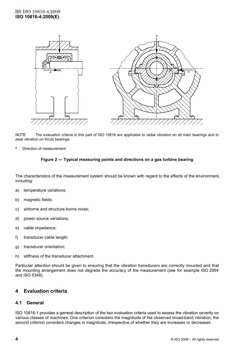
The locations of vibration measurements should be such that they provide adequate sensitivity to the dynamic forces of the machine. Care should be taken to ensure that the measurement equipment is not unduly influenced by external sources, such as combustion vibration, gear mesh vibration, and airborne and structure-borne noise. Typically, this requires measuring in two radial directions on each main bearing cap or pedestal with a pair of orthogonal transducers, as shown in Figures 1 and 2. The transducers may be placed at any angular location on the bearing housings or pedestals, although vertical and horizontal directions are usually preferred.
A single radial transducer may be used on a bearing cap or pedestal in place of the more typical pair of orthogonal transducers if it is known to provide adequate information on the magnitude of the machine vibration. In general, however, caution should be observed when evaluating vibration from a single transducer at a measurement plane since it might not be oriented to provide a reasonable approximation of the maximum value at that plane.

BS ISO 10816-4:2009ISO 10816-4:2009(E)
© ISO 2009 – All rights reserved 3
It is not common practice to measure axial vibration on the main radial load carrying bearings of gas turbines for continuous operational monitoring. Such measurements are primarily used during periodic vibration surveys or for diagnostic purposes. Hence, in this part of ISO 10816, axial vibration criteria are only provided for thrust bearings where the vibration severity can be judged using the same criteria as for radial vibration (see Table A.1). For other bearings where there are no axial restraints, a less stringent requirement may be used for the evaluation of axial vibration.
NOTE The evaluation criteria in this part of ISO 10816 are applicable to radial vibration on all main bearings and to axial vibration on thrust bearings.
a Direction of measurement.
Figure 1 — Typical measuring points and directions on bearing pedestals and bearing caps
BS ISO 10816-4:2009ISO 10816-4:2009(E)
4 © ISO 2009 – All rights reserved
NOTE The evaluation criteria in this part of ISO 10816 are applicable to radial vibration on all main bearings and to axial vibration on thrust bearings.
a Direction of measurement.
Figure 2 — Typical measuring points and directions on a gas turbine bearing
The characteristics of the measurement system should be known with regard to the effects of the environment, including:
a) temperature variations;
b) magnetic fields;
c) airborne and structure-borne noise;
d) power source variations;
e) cable impedance;
f) transducer cable length;
g) transducer orientation;
h) stiffness of the transducer attachment.
Particular attention should be given to ensuring that the vibration transducers are correctly mounted and that the mounting arrangement does not degrade the accuracy of the measurement (see for example ISO 2954 and ISO 5348).
4 Evaluation criteria
4.1 General
ISO 10816-1 provides a general description of the two evaluation criteria used to assess the vibration severity on various classes of machines. One criterion considers the magnitude of the observed broad-band vibration; the second criterion considers changes in magnitude, irrespective of whether they are increases or decreases.

BS ISO 10816-4:2009ISO 10816-4:2009(E)
© ISO 2009 – All rights reserved 5
The maximum magnitude of vibration measured is defined as the vibration severity. The values presented are the result of experience with machinery of this type and, if due regard is paid to them, acceptable operation can be expected.
NOTE These values are based on previous International Standards, on the results of a survey which was carried out when ISO 7919 (all parts) and ISO 10816 (all parts) were initially developed and on the feedback provided by the experts of ISO/TC 108.
Criteria are presented for steady-state operating conditions at the specified normal operating speed (or speeds) and load ranges, including normal slow changes in power output. Alternative criteria are also presented for other non-steady-state conditions when transient changes are taking place. The vibration criteria represent target values which give provisions for ensuring that gross deficiencies or unrealistic requirements are avoided. They serve as a basis for defining acceptance specifications (see 4.2.2.3).
The criteria relate to the vibration produced by the gas turbine set and not to vibration transmitted from outside the machinery set. If it is suspected that there is a significant influence due to transmitted vibration (either steady-state or intermittent), measurements should be taken with the gas turbine set shut down. If the magnitude of the transmitted vibration is unacceptable, steps should be taken to remedy the situation.
It should be noted that an overall judgement of the vibratory state of a machine is often made on the basis of measurements made on both non-rotating parts and rotating shafts.
4.2 Criterion I: Vibration magnitude
4.2.1 General
This criterion is concerned with defining values for absolute vibration magnitude consistent with acceptable dynamic loads on the bearings and acceptable vibration transmission into the support structure and foundation.
4.2.2 Vibration magnitude at normal operating speeds under steady-state operating conditions
4.2.2.1 General
The maximum vibration magnitude observed at each bearing or pedestal is assessed against four evaluation zones established from international experience.
4.2.2.2 Evaluation zones
The following evaluation zones are defined to permit an assessment of the vibration of a given machine under steady-state conditions at normal operating speed (or speeds) and to provide guidelines on possible actions.
Zone A: The vibration of newly commissioned machines normally falls within this zone.
Zone B: Machines with vibration within this zone are normally considered acceptable for unrestricted long-term operation.
Zone C: Machines with vibration within this zone are normally considered unsatisfactory for long-term continuous operation. Generally, the machine may be operated for a limited period in this condition until a suitable opportunity arises for remedial action.
Zone D: Vibration values within this zone are normally considered to be of sufficient severity to cause damage to the machine.
NOTE For transient operation, see 4.2.4.

BS ISO 10816-4:2009ISO 10816-4:2009(E)
6 © ISO 2009 – All rights reserved
4.2.2.3 Acceptance criteria
Acceptance criteria shall always be subject to agreement between the machine supplier and purchaser prior to installation. The evaluation zones provide a basis for defining acceptance criteria for new or refurbished machines.
NOTE Historically, for new machines, acceptance criteria have been specified in zone A or zone B, but would normally not exceed 1,25 times the zone A/B boundary.
4.2.2.4 Evaluation zone boundaries
The zone boundary values are given in Table A.1. They apply to radial vibration measurements on all bearings and to axial vibration measurements on thrust bearings when taken under steady-state conditions at normal operating speed (or speeds). The numerical values assigned to the zone boundaries were established from representative data provided by manufacturers and users. There was inevitably a significant spread in the data. The values given in Table A.1 do nevertheless give provisions for ensuring that gross deficiencies or unrealistic requirements are avoided.
Higher vibration is permitted at other measurement positions and during transient conditions (see 4.2.4).
In most cases, the values given in Table A.1 are consistent with ensuring that the dynamic loads transmitted to the bearing support structure and foundation are acceptable. However, in certain cases, there can be specific features or available experience associated with a particular machine type which can require other values (higher or lower) to be used for the zone boundaries. The following are examples.
a) The machine vibration can be influenced by its mounting system and coupling arrangement between rotors. Higher bearing vibration may therefore be permitted for flexible bearing supports when the shaft relative vibration in the measurement direction is low, indicating that the dynamic forces transmitted to the support structure are also low. It may then be acceptable, based on demonstrated satisfactory operating history, for the zone boundary values given in Table A.1 to be increased.
b) For relatively lightly loaded bearings or other more flexible bearings, other criteria based on the detailed machine design may be used.
NOTE 1 Different values can apply for measurements taken at different bearings on the same rotor line.
In general, when higher zone boundary values are used it can be necessary for technical justification to be provided to confirm that the machine's reliability is not compromised by operating with higher vibration. This could be based, for example on the detailed features of the machine or on successful operating experience with machines of similar structural design and support.
NOTE 2 This part of ISO 10816 does not provide different evaluation zone values for gas turbine sets mounted on rigid and flexible foundations. This is consistent with ISO 7919-4, which deals with shaft vibration measurements for the same class of machines. However, it is possible that this part of ISO 10816 and ISO 7919-4 will be revised in the future to give different criteria with respect to support flexibility, if additional analysis of survey data on such machines shows it to be warranted.
The common measurement parameter for assessing machine vibration severity is velocity. Table A.1 presents the evaluation zone boundaries based on broad-band r.m.s. (root-mean-square) velocity measurements. In some cases, however, it was customary to measure vibration with instruments scaled to read peak rather than r.m.s. vibration velocity values. If the vibration consists mainly of one frequency component (e.g. for gas turbine sets, it is common for the vibration to be predominantly at the operating frequency of the machine), a simple relationship exists between the peak and r.m.s. values and the zone boundaries of Table A.1 can be readily expressed as zero-to-peak values by multiplying by 2 . Alternatively, the measured peak vibration values can be divided by 2 and judged against the r.m.s. criteria of Table A.1.
NOTE 3 A different factor can be required if instrumentation measuring true peak values is used.

BS ISO 10816-4:2009ISO 10816-4:2009(E)
© ISO 2009 – All rights reserved 7
4.2.3 Operational limits for steady-state operation
4.2.3.1 General
For long-term steady-state operation, it is common practice to establish operational vibration limits. These limits take the form of ALARMS and TRIPS.
ALARMS: To provide a warning that a defined vibration limit has been reached or a significant change has occurred, at which remedial action may be necessary. In general, if an ALARM occurs, operation can continue for a period whilst investigations are carried out (e.g. examine the influence of load, speed or other operational parameters) to identify the reason for the change in vibration and to define any remedial action.
TRIPS: To specify the magnitude of vibration beyond which further operation of the machine can cause damage. If the TRIP limit is exceeded, immediate action should be taken to reduce the vibration or the machine should be shut down.
Different operational limits, reflecting differences in dynamic loading and support stiffness, may be specified for different measurement positions and directions.
4.2.3.2 Setting of ALARMS
The ALARM limits may vary for individual machines. It is recommended that the values chosen normally be set relative to baseline values determined from experience for the measurement position or direction for that particular machine.
It is recommended that the ALARM limit be set higher than the baseline by an amount equal to 25 % of the zone boundary B/C. The ALARM limit should not normally exceed 1,25 times the zone boundary B/C. If the baseline value is low, the ALARM limit may be less than the zone B/C boundary (see the example in Annex B).
Where there is no established baseline (e.g. with a new machine), the initial ALARM setting should be based either on experience with other similar machines or relative to agreed acceptance values. In cases where no such data are available, the ALARM limit for steady-state operation at normal operating speed should not exceed the zone boundary B/C. After a period of time, the steady-state baseline values become established and the ALARM setting should be adjusted accordingly.
Where the vibration signal is non-steady and non-repetitive, some method of averaging is required.
If the steady-state baseline changes (e.g. after a machine overhaul), the ALARM setting should be revised accordingly. Different operational ALARM settings may subsequently exist for different measurement positions on the machine, reflecting differences in dynamic loading and bearing support stiffness.
An example of establishing ALARM limits is given in Annex B.
4.2.3.3 Setting of TRIPS
The TRIP limits generally relate to the mechanical integrity of the machine and are dependent on any specific design features which have been introduced to enable the machine to withstand abnormal dynamic forces. For example the bearings of many heavy-duty gas turbines are mounted on flexible supports which allow significantly higher vibration to be tolerated than would be the case for other types of machines which employ stiffer supports. The values used are generally the same for all machines of similar design and would not normally be related to the steady-state baseline value used for setting ALARMS.
There can be differences for machines of different design and it is not possible to give more precise guidelines for absolute TRIP limits. In general, the TRIP limit is within zone C or D, but it is recommended that it not exceed 1,25 times the zone boundary C/D. However, experience with a specific machine may prescribe a different limit.

BS ISO 10816-4:2009ISO 10816-4:2009(E)
8 © ISO 2009 – All rights reserved
Gas turbine sets are often controlled by an automatic control system which shuts down the machine if the TRIP vibration limits are exceeded. In order to avoid unnecessary trips due to spurious signals, it is common practice to adopt a control logic using multiple transducers and to define a time delay before any automatic action is initiated to shut down the machine automatically. Therefore, if a vibration TRIP signal is received, an action to proceed should only be acted upon if the signal is confirmed by at least two independent transducers and exceeds the defined limit for a specified finite delay time. Typically, the delay time should be in the range of 1 s to 3 s. It might also be prudent to introduce a second ALARM between the ALARM and TRIP limits to alert operators that they are approaching the TRIP limit, so that they can take any corrective action (e.g. load reduction or other manufacturer's recommendations) to avoid tripping the unit from full load.
4.2.4 Vibration magnitude during non steady-state conditions (transient operation)
4.2.4.1 General
The vibration values given in Annex A are specified with regard to the long-term operation of the gas turbine at the specified steady-state operating conditions. Higher vibration can be tolerated during the time that it takes for the gas turbine to reach thermal equilibrium when the operating conditions are changing at normal operating speed (or speeds) and during run up or run down. These higher values may exceed the steady-state ALARM and TRIP limits specified in 4.2.3. For such cases, a “trip multiplier” may be introduced which automatically raises the ALARM and TRIP limits for the period until steady-state conditions are established (see 4.2.4.4).
For gas turbines operating under non-steady-state conditions, such transient changes are generally associated with significant thermal variations, which strongly influence the vibration behaviour of the engine. Special design features are introduced to deal with such conditions, but it is inevitable for there to be a greater variation in the experienced vibration during speed changes (e.g. run up, run down) and while thermal changes are taking place (e.g. during start up, initial loading and load changes), than for other machine types where more gradual vibration changes are experienced. Consequently, higher transient vibrations are normally acceptable for gas turbines.
As with the steady-state vibration, any acceptance criteria for specific cases shall be subject to agreement between the machine supplier and purchaser. However, provisions are given in this clause which should ensure that gross deficiencies or unrealistic requirements are avoided.
4.2.4.2 Vibration magnitude during transient operation at normal operating speed
This includes operation at no load, initial loading or during rapid load or power factor changes and any other operational conditions of relatively short duration. During such conditions, the vibration magnitude shall normally be considered to be acceptable, provided it does not exceed the zone boundary C/D. The TRIP and ALARM limits should be adjusted accordingly.
4.2.4.3 Vibration magnitude during run up, run down and overspeed
The gas turbine set shall have been adequately conditioned prior to running up to ensure that there are no temporary bends or bows present which would cause abnormal excitation. In particular, it is recommended that, where appropriate, a period of barring and/or low-speed rotation be carried out before commencing to run up. Following this, if the gas turbine set is fitted with shaft vibration transducers (see ISO 7919-4), slow-roll shaft displacement measurements may be carried out to assess the amount of runout obtained at low speed (where the measurements are not influenced by the lowest resonance speed), when stable bearing oil films have been established but centrifugal effects are negligible. The shaft displacement measured at this speed, together with other reference parameters, should be checked to be within previously established satisfactory experience. Such checks provide a basis for judging whether the state of the shaft line is satisfactory; for example whether a temporary bend is present in the shaft or whether there is any lateral or angular misalignment between couplings (“crank effect”). Furthermore, during the run up, it is recommended that the bearing vibration be assessed before a critical/resonant speed is reached and compared with typical vibration vectors obtained under the same conditions during previous satisfactory runs. If any significant differences are observed, it can be advisable to take further action before proceeding (e.g. hold or reduce speed until the vibration stabilizes or returns to previous values, carry out a more detailed investigation or check operational parameters).

BS ISO 10816-4:2009ISO 10816-4:2009(E)
© ISO 2009 – All rights reserved 9
If there is no provision for barring or for measuring slow roll shaft displacement, observe alternative recommendations given by the supplier.
During run up, it can be necessary to hold at a particular speed (e.g. during purging). If so, care should be taken to ensure that there is an adequate margin between the hold speed and any critical/resonant speeds where significant amplification of the vibration could occur.
The specification of vibration limits during run up, run down and overspeed can vary depending on particular machine constructional features, or the specific operational requirements. For example higher vibration values may be acceptable for a base load unit for which there may be only a small number of starts, whereas more stringent limits can apply for a unit which undergoes regular two-shift operation and can be subject to specific time constraints for achieving guaranteed output levels. Furthermore, the vibration magnitude when passing through critical/resonant speeds during run up and run down are strongly influenced by the damping and the rate of change of speed (for the sensitivity of machines to unbalance, see ISO 10814).
Different ALARM limits from those adopted for normal steady-state operating conditions apply during run up, run down and overspeed. They should normally be set relative to established values determined from experience during run up, run down or overspeed for the particular machine. It is recommended that the ALARM limit during run up, run down and overspeed be set above these values by an amount equal to 25 % of the zone boundary B/C.
In those cases where no reliable established data are available, the ALARM limit during run up, run down or overspeed should not exceed the zone boundary C/D.
Different approaches are used with regard to setting a TRIP during run up or run down. For example if excessive vibrations build up during run up, it is possibly more appropriate to reduce speed rather than to initiate a TRIP. On the other hand, there is little point in initiating a high vibration TRIP during run down, since this does not change the action (i.e. to run down) which has already been taken. However, if the gas turbine has an automatic control system, it can be necessary to define TRIP limits during run up or run down. In such cases, the TRIP limits should be increased by a similar proportion to that adopted for the ALARM limits.
NOTE During run up and run down, the highest vibration normally occurs when passing through critical/resonant speeds due to dynamic magnification effects. At other speeds, lower vibration is normally expected.
There can be drawbacks in using a constant-velocity criterion at lower speeds because, although the dynamic forces transmitted to the bearings/housings are acceptable, the corresponding vibration displacements can be of concern for ancillary equipment attached to the bearing housings (e.g. oil pipes). In such cases, it can be necessary to vary the ALARM and TRIP settings as speed reduces. In particular, it is recommended that the above ALARM and TRIP limits not be applied for rotational speeds below 20 % of normal operating speed (see Annex C).
4.2.4.4 Use of “trip multiplier”
In some cases, gas turbine sets are fitted with control systems which automatically shut down the set if the TRIP limits are exceeded. In order to avoid unnecessary trips when operating under transient conditions during which higher vibration is permitted, a “trip multiplier” may be introduced which automatically increases the steady-state ALARM and TRIP limits to reflect the revised values given in 4.2.4.2 and 4.2.4.3.
The “trip multiplier” would normally be activated during acceleration/deceleration of the rotor to/from normal operating speed (but not during any hold speed) and, if appropriate, during the initial loading transient (normally the first few hours) after reaching normal operating speed, and for short periods after any sudden, substantial load changes to allow the thermal conditions to stabilize. Different “trip multiplier” settings, based on established experience, may apply for each of these operational conditions. The actual “trip multiplier” values vary for different gas turbines and should be based on previous satisfactory operational experience.

BS ISO 10816-4:2009ISO 10816-4:2009(E)
10 © ISO 2009 – All rights reserved
4.3 Criterion II: Change in vibration magnitude under steady-state conditions at normal operating speed
This criterion provides an assessment of a change in vibration magnitude from a previously established reference value for particular steady-state conditions. A significant increase or decrease in bearing vibration magnitude can occur, which requires some action even though zone C of Criterion I has not been reached. Such changes can be instantaneous or progressive with time and can indicate that damage has occurred or be a warning of an impending failure or some other irregularity. Criterion II is specified on the basis of the change in bearing vibration magnitude occurring under steady-state operating conditions at normal operating speed. This includes small changes in variables such as power output, but does not include large, rapid changes in output, which are dealt with in 4.2.4.2.
CAUTION — Care should be taken in applying this criterion for machines with synchronizing clutches where vibration step changes can occur due to normal variations in axial expansion.
The reference value for this criterion is the typical, reproducible normal vibration, known from previous measurements for the specific operating conditions. If the vibration magnitude changes by a significant amount (typically 25 % of the zone boundary B/C), steps should be taken to ascertain the reasons for the change. Such action should be taken regardless of whether the change causes an increase or decrease in the vibration magnitude. A decision on what action to take, if any, should be made after consideration of the maximum value of vibration and whether the machine has stabilized at a new condition. In particular, if the rate of change of vibration is significant, action should be taken even though the limit defined above has not been exceeded.
When Criterion II is applied, the vibration measurements being compared shall be taken at the same transducer location and orientation and, as far as practicable, under the same machine operating conditions.
It should be appreciated that a criterion based on change of vibration has limited application, since significant changes of varying magnitude and rates can and do occur in individual frequency components, but the importance of these is not necessarily reflected in the broad-band vibration signal (see ISO 10816-1). For example the propagation of a crack in a rotor can introduce a progressive change in vibration components at multiples of rotational frequency, but their magnitude can be small relative to the amplitude of the once-per-revolution rotational frequency component. Consequently, it can be difficult to identify the effects of the crack propagation by looking at the change in the broad-band vibration only. Therefore, although monitoring the change in broad-band vibration gives some indication of potential problems, it can be necessary in certain applications to use measurement and analysis equipment which is capable of determining the trends of the vibration vector changes that occur for individual frequency components. This equipment can be more sophisticated than that used for normal supervisory monitoring and its use and application requires specialist knowledge. The specification of detailed criteria for measurements of this type is beyond the scope of this part of ISO 10816 (see 4.5).
4.4 Supplementary procedures/criteria
The measurement and evaluation of vibration given in this part of ISO 10816 may be supplemented or replaced by shaft vibration measurements (see ISO 7919-4). There is no simple way to relate bearing housing vibration to shaft vibration or vice versa. The difference between the shaft absolute and shaft relative measurements is related to the bearing housing vibration, but generally is not numerically equal to it because of the relative dynamic flexibility of the bearing oil film and support structure at the operating speed, the different positions at which the probes are mounted and the influence of phase angle differences. Thus, when the criteria of this part of ISO 10816 and those of ISO 7919-4 are both applied in the assessment of machine vibration, independent shaft and bearing housing (or pedestal) vibration measurements shall be made. If application of the different criteria leads to different assessments of vibration severity, the more restrictive zone classification generally applies, unless there is significant experience to the contrary.
4.5 Evaluation based on vibration vector information
The evaluation considered in this part of ISO 10816 is limited to broad-band vibration without reference to frequency components or phase. In most cases, this is adequate for acceptance testing and for operational monitoring purposes. However, for long-term condition monitoring purposes and for diagnostics, the use of

BS ISO 10816-4:2009ISO 10816-4:2009(E)
© ISO 2009 – All rights reserved 11
vibration vector information is particularly useful for detecting and defining changes in the dynamic state of the machine. In some cases, these changes would go undetected when using only broad-band vibration measurements (see ISO 10816-1:1995, Annex D).
Phase- and frequency-related vibration information is being used increasingly for monitoring and diagnostic purposes. The specification of criteria for this, however, is beyond the scope of this part of ISO 10816. They are dealt with in greater detail in ISO 13373 (all parts), which give provisions for the vibration condition monitoring of machines.

BS ISO 10816-4:2009ISO 10816-4:2009(E)
12 © ISO 2009 – All rights reserved
Annex A (normative)
Evaluation zone boundaries
The values given in Table A.1 apply to radial vibration measurements on all bearings and to axial vibration measurements on thrust bearings, when taken under steady-state operating conditions at normal operating speed. Figures 1 and 2 show typical measurement positions. The values given are for ensuring that gross deficiencies or unrealistic requirements are avoided. In certain cases, specific features associated with a particular machine type can require the use of different zone boundary values (see 4.2.2.4). Higher vibration can be permitted at other measurement positions and under transient conditions (see 4.2.4).
NOTE Historically, acceptance criteria have been specified in zone A or zone B, but would normally not exceed 1,25 times the zone A/B boundary (see 4.2.2.3).
Table A.1 — Recommended values for bearing housing or pedestal vibration velocity at zone boundaries for gas turbines
Zone boundary r.m.s. vibration velocity at zone boundaries mm/s
A/B 4,5
B/C 9,3
C/D 14,7

BS ISO 10816-4:2009ISO 10816-4:2009(E)
© ISO 2009 – All rights reserved 13
Annex B (informative)
Example of setting ALARM and TRIP values
Consider the case of a 3 000 r/min gas turbine. The operational ALARM settings for a new machine, for which there is no prior knowledge of bearing vibration, is normally set within zone B. The specific value is often set by mutual agreement between the supplier and purchaser. For this example, assume it has been set initially for each bearing at the zone B/C boundary, which corresponds to an r.m.s value of 9,3 mm/s (see Table A.1).
After a period in service when the normal vibration characteristics have been established, consideration can be given to changing the ALARM limits to reflect the typical steady baseline values of vibration at each bearing. Using the procedure described in 4.2.3.2 as the basis, the ALARM may be set for each bearing to equal the sum of the typical steady-state value obtained from experience with the specific machine, and 25 % of the zone B/C boundary. For example if the typical steady-state r.m.s. vibration at a particular bearing were 5 mm/s, a new ALARM limit of 7,3 mm/s (i.e. 5 mm/s + 0,25 × 9,3 mm/s) would be adopted that is within zone B. If at another bearing the typical steady-state r.m.s. vibration were 6,7 mm/s, the new ALARM limit would be 9,0 mm/s. However, in view of the small difference between this and the initial value, it can be decided that the initial value (9,3 mm/s) would be retained.
The TRIP limit would remain at an r.m.s. value of 14,7 mm/s according to Criterion I. The basis for this is that the TRIP limit is a fixed value corresponding to the maximum vibration to which the machine should be subjected.
During transient operation the above limits may be increased as described in 4.2.4.

BS ISO 10816-4:2009ISO 10816-4:2009(E)
14 © ISO 2009 – All rights reserved
Annex C (informative)
Cautionary notes about the use of vibration velocity criteria
at low rotational speeds
For the reasons explained in this annex, it is recommended that the velocity criteria provided in this part of ISO 10816 not be applied for low frequencies. For monitoring the vibration at lower speeds, more specialized instrumentation can be required to allow evaluation against other criteria, such as constant displacement, which are outside the scope of this part of ISO 10816. Alternatively, consideration would have to be given to monitoring shaft vibration (see ISO 7919-4).
The rationale for using vibration velocity measured on non-rotating parts as a basis for characterizing the severity of machine vibration has been derived from field experience (e.g. the pioneering work of T. C. Rathbone in the 1930s, see Reference [13]), together with an understanding of fundamental mechanics. Based on this, it has been accepted for many years that vibration with the same r.m.s. velocity in the frequency range 10 Hz to 1 000 Hz can generally be considered to be of equal severity. A particular advantage of this is that if vibration velocity is used as an evaluation parameter, the same assessment criteria can be used regardless of the frequency of vibration or the operating speed of the machine. Conversely, if displacement or acceleration were used for evaluation, the assessment criteria would vary with frequency because the relationship between vibration displacement and velocity is inversely proportional to frequency and that between acceleration and velocity is directly proportional to frequency.
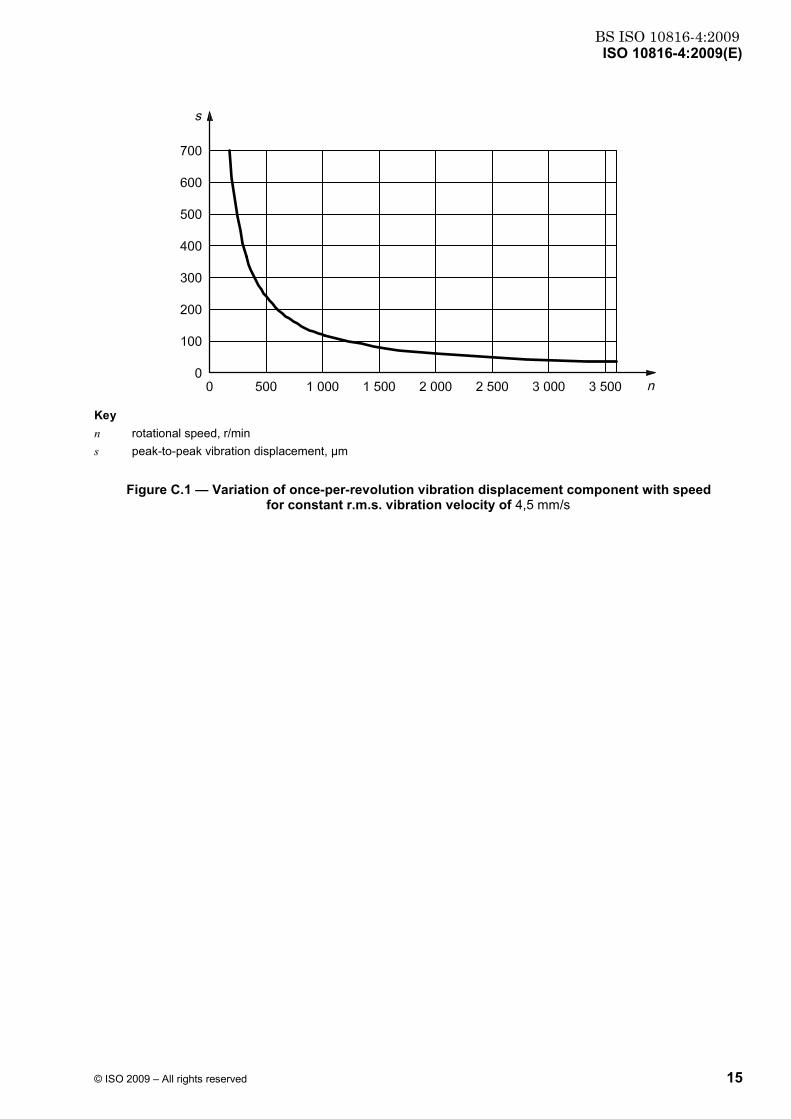
The use of a constant-velocity criterion alone becomes impractical at low and high frequencies where the influence of displacement and acceleration, respectively, becomes significant. For low frequencies, this is demonstrated in Figure C.1 which shows how the vibration displacement corresponding to a constant velocity of 4,5 mm/s (the zone A/B boundary value at normal operating speed) varies with speed for a once-per-revolution vibration frequency component (e.g. due to unbalance) during run down from 3 600 r/min.
Figure C.1 is simply a mathematical relationship which shows how a constant velocity transposes to displacement at different speeds. It does, however, demonstrate how a constant-velocity criterion can lead to a progressively increasing displacement of the bearing housing as the speed reduces. In such cases, although the dynamic forces transmitted to the bearing housing would be acceptable, the vibration displacements can be of concern at lower speeds for ancillary equipment attached to the bearing housing (e.g. oil pipes).
Figure C.1 should not be confused with a normal run-up or run-down response curve for which, apart from when passing through resonant speeds (critical speeds), the vibration velocity normally reduces as the speed is reduced. In practice, if the vibration velocity at normal operating speed is acceptable, it usually reduces at lower speeds and the corresponding vibration displacements at lower speeds would be acceptable. It follows that if significant vibration velocities are recorded at low speed during run up, even if they are below the values specified in this part of ISO 10816 and especially if they are significantly outside the range normally experienced at the same speed for that particular machine, action should be taken to understand the reasons for the higher vibration values and to establish whether it is safe to continue to higher speeds (see 4.2.3.3).
BS ISO 10816-4:2009ISO 10816-4:2009(E)
© ISO 2009 – All rights reserved 15
Key n rotational speed, r/min s peak-to-peak vibration displacement, µm
Figure C.1 — Variation of once-per-revolution vibration displacement component with speed for constant r.m.s. vibration velocity of 4,5 mm/s

BS ISO 10816-4:2009ISO 10816-4:2009(E)
16 © ISO 2009 – All rights reserved
Bibliography
[1] ISO 2041, Mechanical vibration, shock and condition monitoring — Vocabulary
[2] ISO 2954, Mechanical vibration of rotating and reciprocating machinery — Requirements for instruments for measuring vibration severity
[3] ISO 3977-3, Gas turbines — Procurement — Part 3: Design requirements
[4] ISO 5348, Mechanical vibration and shock — Mechanical mounting of accelerometers
[5] ISO 7919-1, Mechanical vibration of non-reciprocating machines — Measurements on rotating shafts and evaluation criteria — Part 1: General guidelines
[6] ISO 7919-2, Mechanical vibration — Evaluation of machine vibration by measurements on rotating shafts — Part 2: Land-based steam turbines and generators in excess of 50 MW with normal operating speeds of 1 500 r/min, 1 800 r/min, 3 000 r/min and 3 600 r/min
[7] ISO 7919-3, Mechanical vibration — Evaluation of machine vibration by measurements on rotating shafts — Part 3: Coupled industrial machines
[8] ISO 7919-5, Mechanical vibration — Evaluation of machine vibration by measurements on rotating shafts — Part 5: Machine sets in hydraulic power generating and pumping plants
[9] ISO 8579-2, Acceptance code for gears — Part 2: Determination of mechanical vibrations of gear units during acceptance testing
[10] ISO 10814, Mechanical vibration — Susceptibility and sensitivity of machines to unbalance
[11] ISO 13373-1, Condition monitoring and diagnostics of machines — Vibration condition monitoring — Part 1: General procedures
[12] ISO 13373-2, Condition monitoring and diagnostics of machines — Vibration condition monitoring — Part 2: Processing, analysis and presentation of vibration data
[13] RATHBONE, T.C., Vibration tolerances, Power Plant Engineering, 1939

BS ISO 10816-4:2009

BS ISO 10816-4:2009ISO 10816-4:2009(E)
ICS 17.160; 27.040 Price based on 16 pages
© ISO 2009 – All rights reserved

BS ISO 10816-4:2009
This page has been intentionally left blank

BS ISO10816-4:2009
BSI GroupHeadquarters 389Chiswick High Road,London, W4 4AL, UKTel +44 (0)20 8996 9001Fax +44 (0)20 8996 7001www.bsigroup.com/standards
BSI - British Standards InstitutionBSI is the independent national body responsible for preparing BritishStandards. It presents the UK view on standards in Europe and at theinternational level. It is incorporated by Royal Charter.
Revisions
British Standards are updated by amendment or revision. Users of BritishStandards should make sure that they possess the latest amendments oreditions.
It is the constant aim of BSI to improve the quality of our products and services.We would be grateful if anyone finding an inaccuracy or ambiguity while usingthis British Standard would inform the Secretary of the technical committeeresponsible, the identity of which can be found on the inside front cover. Tel:+44 (0)20 8996 9000. Fax: +44 (0)20 8996 7400.
BSI offers members an individual updating service called PLUS which ensuresthat subscribers automatically receive the latest editions of standards.
Buying standards
Orders for all BSI, international and foreign standards publications should beaddressed to Customer Services. Tel: +44 (0)20 8996 9001. Fax: +44 (0)20 89967001 Email: [email protected] You may also buy directly using a debit/creditcard from the BSI Shop on the Website http://www.bsigroup.com/shop
In response to orders for international standards, it is BSI policy to supply theBSI implementation of those that have been published as British Standards,unless otherwise requested.
Information on standards
BSI provides a wide range of information on national, European andinternational standards through its Library and its Technical Help to ExportersService. Various BSI electronic information services are also available whichgive details on all its products and services. Contact Information Centre. Tel:+44 (0)20 8996 7111 Fax: +44 (0)20 8996 7048 Email: [email protected]
Subscribing members of BSI are kept up to date with standards developmentsand receive substantial discounts on the purchase price of standards. For detailsof these and other benefits contact Membership Administration. Tel: +44 (0)208996 7002 Fax: +44 (0)20 8996 7001 Email: [email protected]
Information regarding online access to British Standards via British StandardsOnline can be found at http://www.bsigroup.com/BSOL
Further information about BSI is available on the BSI website at http://www.bsigroup.com
Copyright
Copyright subsists in all BSI publications. BSI also holds the copyright, in theUK, of the publications of the international standardization bodies. Except aspermitted under the Copyright, Designs and Patents Act 1988 no extract maybe reproduced, stored in a retrieval system or transmitted in any form or by anymeans – electronic, photocopying, recording or otherwise – without prior writtenpermission from BSI.
This does not preclude the free use, in the course of implementing the standard,of necessary details such as symbols, and size, type or grade designations. Ifthese details are to be used for any other purpose than implementation then theprior written permission of BSI must be obtained.
Details and advice can be obtained from the Copyright and Licensing Manager.Tel: +44 (0)20 8996 7070 Email: [email protected]