Mechanical Tic-Tac-Toe Board - web.wpi.edu · There are 255,168 possible games in tic-tac-toe. The...
45
Mechanical Tic-Tac-Toe Board A Major Qualifying Project Report submitted to the Faculty of the WORCESTER POLYTECHNIC INSTITUTE in partial fulfilment of the requirements for the Degree of Bachelor of Science. By: Shane Bell Timothy Bill Abigail McAdams Taylor Teed Spring 2018 Submitted to: Professor Robert Daniello Mechanical Engineering Department
Transcript of Mechanical Tic-Tac-Toe Board - web.wpi.edu · There are 255,168 possible games in tic-tac-toe. The...
Mechanical Tic-Tac-Toe Board
A Major Qualifying Project Report submitted to the Faculty of the WORCESTER
POLYTECHNIC INSTITUTE in partial fulfilment of the requirements for the Degree of
Bachelor of Science.
By:
Shane Bell
Timothy Bill
Abigail McAdams
Taylor Teed
Spring 2018
Submitted to:
Professor Robert Daniello
Mechanical Engineering Department

1
Abstract
The goal of this MQP was to design, test and build a fully mechanical computer capable of playing
tic-tac-toe against a human being. There is no question that modern computers could solve this
problem more efficiently. However, our team aims to prove that old school technology still has a
place in society today. Our design includes numerous methods of mechanical motion that are found
in many designs today such as an escapement, gears, racks and pinions, and hydraulics. The
machine was built almost entirely in the Higgins machine shop, except for a couple parts that were
either cut with a water-jet or purchased. Our design uses an indexing module to detect position and
data stored on a physical punch card to produce the best strategic answer. If the user makes the
first move, the computer will never lose, only win or tie.

2
Acknowledgements Our group would like that thank our advisor Robert Daniello for his guidance and support
throughout the duration of our project, Thomas Kouttron and Michael Cooke for their positive
attitudes and constant aid in manufacturing, and Dane Kouttron for allowing access to machines
not available within WPI facilities. We would also like to thank James Loiselle, Ian Anderson,
Karl Ehlers, and Cam Collins for their good hearted aid, teaching our team the ins and outs of
computer aided manufacturing and helping to figure out machining problems that we could not.
3
Table of Contents Abstract ........................................................................................................................................... 1
Acknowledgements ......................................................................................................................... 2
Table of Figures .............................................................................................................................. 5
1.0 Introduction ............................................................................................................................... 7
2.0 Background ............................................................................................................................... 8
2.1 The Start of Computers ......................................................................................................... 8
2.2 Tic-Tac-Toe ........................................................................................................................... 8
2.2.1. Move 1: ........................................................................................................................ 10
2.2.2. Move 2: ........................................................................................................................ 11
2.2.3. Move 3: ........................................................................................................................ 11
2.2.4. Move 4: ........................................................................................................................ 12
2.2.5. Move 5: ........................................................................................................................ 12
2.2.6. Move 6: ........................................................................................................................ 12
2.2.7. Move 7: ........................................................................................................................ 13
3.0 Methodology ........................................................................................................................... 13
3.1 Objective 1: Design a Compact 3D Model ......................................................................... 14
3.1.1 Preliminary Designs ..................................................................................................... 14
3.1.2. Resets .............................................................................................................................. 24
3.1.2.1 Reset Mechanisms for Tines: .................................................................................... 24
3.1.2.2 Gear Box Reset: ......................................................................................................... 25
3.1.2.3 Tile Reset: .................................................................................................................. 25
3.1.3 Calculations and Tolerancing ........................................................................................... 25
3.1.3.1 Creating a Numerical System of Data ....................................................................... 25
3.1.3.1.1 The First Move: .......................................................................................................... 26
3.1.3.2 Binary Format of Numerical Data Compilation ........................................................ 30
3.1.3.3 Hydraulic System ...................................................................................................... 31
3.1.3.4 Tolerancing ................................................................................................................ 32
3.2 Objective 2: Machining and Assembly ................................................................................... 32
3.2.1 Machining Process ........................................................................................................... 32
3.2.1.1 Manual Machining ..................................................................................................... 32
3.2.1.2 Computer-Numerical Control Machining ................................................................. 33
4
3.2.1.2.1 Mini Mill................................................................................................................. 33
3.2.1.2.2 ST-10 ...................................................................................................................... 34
3.2.2 Assembly .......................................................................................................................... 34
4.1 Results and Discussion ........................................................................................................... 35
4.1.1 Objective 1: Design a Compact 3D Model ...................................................................... 35
4.1.1.1 Size Constraints ......................................................................................................... 35
4.1.1.2 Design with Intent to Manufacture ............................................................................ 36
4.1.1.3 Time Constraints........................................................................................................ 36
4.1.2 Objective 2: Machining and Assembly ............................................................................ 37
4.1.2.1 Budget ........................................................................................................................ 37
4.1.2.2 Scrapped Parts ........................................................................................................... 37
4.1.3 Objective 3: Testing and Repeatability ............................................................................ 37
4.1.3.1 Playing Tiles .............................................................................................................. 38
4.1.3.2 Tines .......................................................................................................................... 38
4.1.3.3 Crankshaft .................................................................................................................. 38
4.1.3.4 Indexing Gear Box..................................................................................................... 39
4.1.3.5 Gear Box Clutches ..................................................................................................... 39
4.2 Conclusions ............................................................................................................................. 39
4.2.1 Challenges ........................................................................................................................ 39
4.2.1.1 Output ........................................................................................................................ 39
4.2.1.2 Punch Cards ............................................................................................................... 40
4.2.1.3 Machining Availability .............................................................................................. 40
4.2.1.4 Time ........................................................................................................................... 41
References ..................................................................................................................................... 42
Appendices .................................................................................................................................... 43
Appendix I: Analytical Engine .................................................................................................. 43
5
Table of Figures Figure 1: Optimal solution for offensive and defensive game respectively ................................. 10
Figure 2: First Move ..................................................................................................................... 11
Figure 3: Second Move ................................................................................................................. 11
Figure 4: Third Move .................................................................................................................... 11
Figure 5: Fourth Move .................................................................................................................. 12
Figure 6: Fifth Move ..................................................................................................................... 12
Figure 7: Sixth Move .................................................................................................................... 13
Figure 8: Seventh Move ................................................................................................................ 13
Figure 9: Cam System Partial View.............................................................................................. 15
Figure 10: Cam System Full System ............................................................................................ 15
Figure 11: Cams Iteration #2 ........................................................................................................ 15
Figure 12: Physical Library .......................................................................................................... 16
Figure 13: Discs ............................................................................................................................ 16
Figure 14: Discs and Ring............................................................................................................. 17
Figure 15: Music Box ................................................................................................................... 17
Figure 16: Spool Punch Cards ...................................................................................................... 18
Figure 17: Escapement in CAD Model ......................................................................................... 19
Figure 18: 3D Printed Escapement ............................................................................................... 19
Figure 19: Tile Assembly.............................................................................................................. 20
Figure 20: Tile Assembly with Cables and Indexing Mechanism ................................................ 20
Figure 21: Rendering of the Gear Box and an Exploded View of the Gear Box ......................... 21
Figure 22: Diagram of the Punch Card Wheel.............................................................................. 22
Figure 23: Diagram of the Tine Mechanism ................................................................................. 23
Figure 24: CAD Model of the Tine Block Sub-Assembly and CAD Model of an Individual Block
....................................................................................................................................................... 23
Figure 25: CAD Model of the Wedge .......................................................................................... 24
Figure 26: View of the Game Board from the Bottom ................................................................. 24
Figure 27: Naming Convention of Tiles ....................................................................................... 25
Figure 28: Optimal Strategy to play a Defensive Game of Tic-Tac-Toe ..................................... 26
Figure 29:Game Board View after the First Move ....................................................................... 26
Figure 30: Excel Document- First Move ...................................................................................... 26
Figure 31: Game Board View after the Second Move .................................................................. 27
Figure 32: Excel Document- Second Move .................................................................................. 28
Figure 33: Game Board View after the Third Move ..................................................................... 29
Figure 34: Excel Document- Third Move ..................................................................................... 29
Figure 35: Game Board View after the Fourth Move ................................................................... 30
Figure 36: Excel Document- Fourth Move ................................................................................... 30
Figure 37: Binary Excel Document .............................................................................................. 31
Figure 38: Machined Tile Top ...................................................................................................... 33
Figure 39: Machined Spring Tab .................................................................................................. 34
Figure 40: CAD Rendering of Final Design ................................................................................. 35
Figure 41: Analytical Engine [1] .................................................................................................. 43

6
Figure 42: Analytical Engine [2] .................................................................................................. 43
Figure 43: Analytical Engine [3] .................................................................................................. 44
7
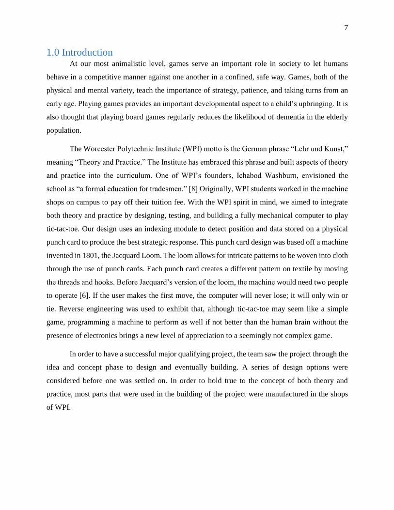
1.0 Introduction At our most animalistic level, games serve an important role in society to let humans
behave in a competitive manner against one another in a confined, safe way. Games, both of the
physical and mental variety, teach the importance of strategy, patience, and taking turns from an
early age. Playing games provides an important developmental aspect to a child’s upbringing. It is
also thought that playing board games regularly reduces the likelihood of dementia in the elderly
population.
The Worcester Polytechnic Institute (WPI) motto is the German phrase “Lehr und Kunst,”
meaning “Theory and Practice.” The Institute has embraced this phrase and built aspects of theory
and practice into the curriculum. One of WPI’s founders, Ichabod Washburn, envisioned the
school as “a formal education for tradesmen.” [8] Originally, WPI students worked in the machine
shops on campus to pay off their tuition fee. With the WPI spirit in mind, we aimed to integrate
both theory and practice by designing, testing, and building a fully mechanical computer to play
tic-tac-toe. Our design uses an indexing module to detect position and data stored on a physical
punch card to produce the best strategic response. This punch card design was based off a machine
invented in 1801, the Jacquard Loom. The loom allows for intricate patterns to be woven into cloth
through the use of punch cards. Each punch card creates a different pattern on textile by moving
the threads and hooks. Before Jacquard’s version of the loom, the machine would need two people
to operate [6]. If the user makes the first move, the computer will never lose; it will only win or
tie. Reverse engineering was used to exhibit that, although tic-tac-toe may seem like a simple
game, programming a machine to perform as well if not better than the human brain without the
presence of electronics brings a new level of appreciation to a seemingly not complex game.
In order to have a successful major qualifying project, the team saw the project through the
idea and concept phase to design and eventually building. A series of design options were
considered before one was settled on. In order to hold true to the concept of both theory and
practice, most parts that were used in the building of the project were manufactured in the shops
of WPI.
8
2.0 Background
2.1 The Start of Computers
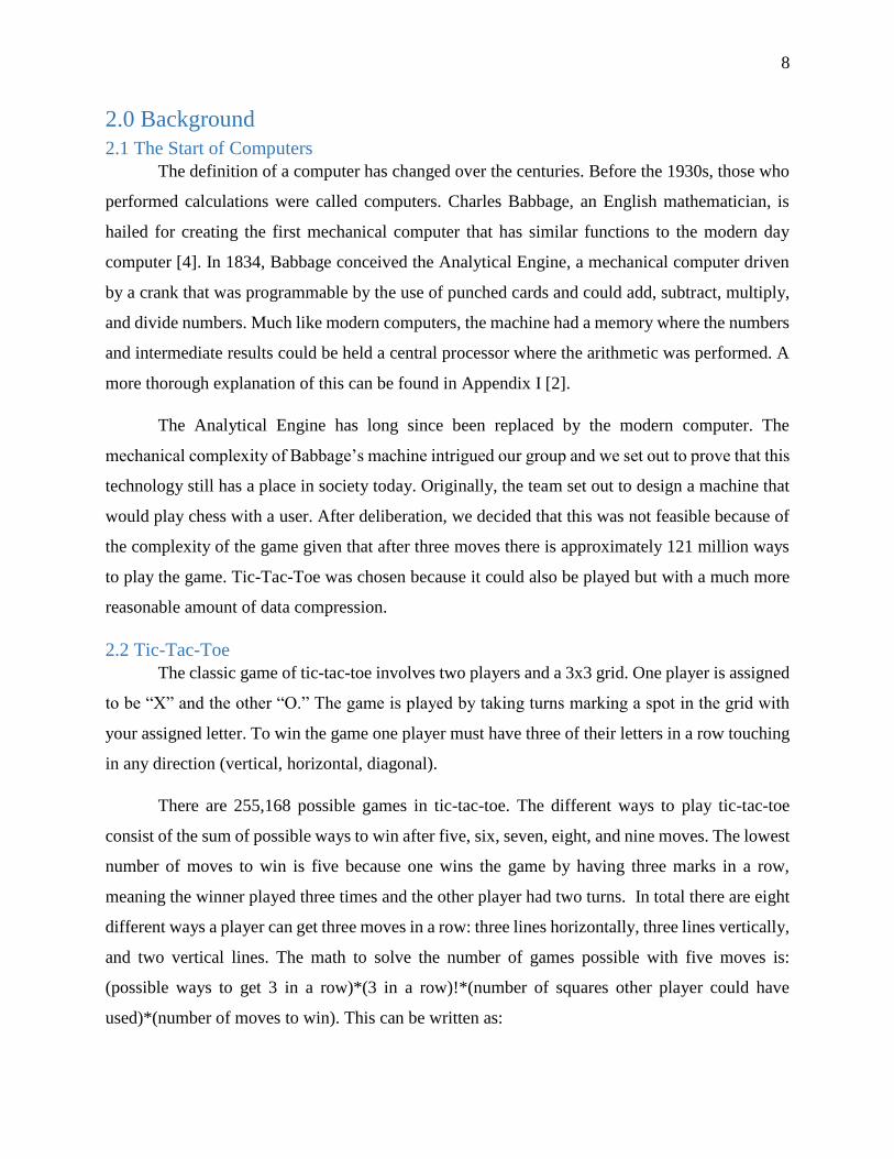
The definition of a computer has changed over the centuries. Before the 1930s, those who
performed calculations were called computers. Charles Babbage, an English mathematician, is
hailed for creating the first mechanical computer that has similar functions to the modern day
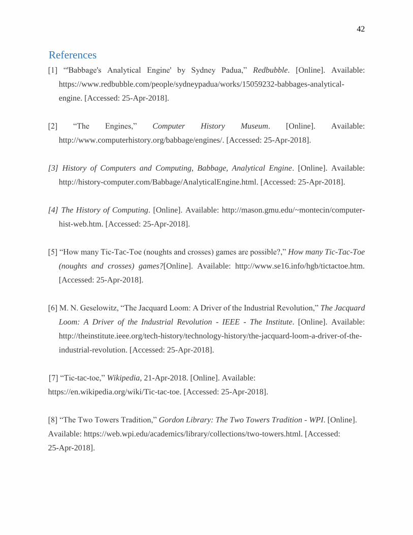
computer [4]. In 1834, Babbage conceived the Analytical Engine, a mechanical computer driven
by a crank that was programmable by the use of punched cards and could add, subtract, multiply,
and divide numbers. Much like modern computers, the machine had a memory where the numbers
and intermediate results could be held a central processor where the arithmetic was performed. A
more thorough explanation of this can be found in Appendix I [2].
The Analytical Engine has long since been replaced by the modern computer. The
mechanical complexity of Babbage’s machine intrigued our group and we set out to prove that this
technology still has a place in society today. Originally, the team set out to design a machine that
would play chess with a user. After deliberation, we decided that this was not feasible because of
the complexity of the game given that after three moves there is approximately 121 million ways
to play the game. Tic-Tac-Toe was chosen because it could also be played but with a much more
reasonable amount of data compression.
2.2 Tic-Tac-Toe
The classic game of tic-tac-toe involves two players and a 3x3 grid. One player is assigned
to be “X” and the other “O.” The game is played by taking turns marking a spot in the grid with
your assigned letter. To win the game one player must have three of their letters in a row touching
in any direction (vertical, horizontal, diagonal).
There are 255,168 possible games in tic-tac-toe. The different ways to play tic-tac-toe
consist of the sum of possible ways to win after five, six, seven, eight, and nine moves. The lowest
number of moves to win is five because one wins the game by having three marks in a row,
meaning the winner played three times and the other player had two turns. In total there are eight
different ways a player can get three moves in a row: three lines horizontally, three lines vertically,
and two vertical lines. The math to solve the number of games possible with five moves is:
(possible ways to get 3 in a row)*(3 in a row)!*(number of squares other player could have
used)*(number of moves to win). This can be written as:
9
8*3!*6*5=1440
To win after six moves, the equation used is:
(8*3!*6*5*4)-(6*3!*2*3!)=5328
The reason for the subtraction in this equation is because now both players have three
moves on the board so all of the other possible outcomes where player one could have gotten three
in a row must be excluded considering player two won the game on their third move.
To win after seven moves, the equation used is:
(8*3*6*3!*5*4*3)-(6*3*6*3!*3!)= 47952
Again, as seen with winning after six moves, the possible combinations of three in a row
for the player that did not win had to be removed. The winner of this game already had three moves
on the board which were not all in a row before the winning mark was played. A similar technique
was used for calculating the number of ways to win after eight moves, resulting in the equation:
(8*3*6*3!*5*4*3*2)-(6*3*6*3!*2*4!)= 72576
To calculate the amount of games that can be played to the ninth square, math must be
done to calculate both a win, or three moves in a row, along with all of the possible draws. This
math can be simply done as 9!-4!(wins in five moves)-3!(wins in six moves)-2!(wins in seven
moves)-1!(wins in eight moves). The math to solve the possible ways to win was more complex
and not necessary because only the total number of games were of interest. The written out
equation for this is:
9!-[4!(1440)]-[3!(5328)]-[2!(47952)]-[1!(72576)]= 127872
To find the total number of games possible, the totals per moves needed for a game to end
are summed together resulting in:
1440+5328+47952+72576+127872= 255168 [5]
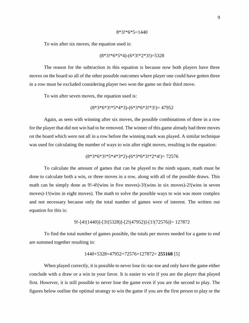
When played correctly, it is possible to never lose tic-tac-toe and only have the game either
conclude with a draw or a win in your favor. It is easier to win if you are the player that played
first. However, it is still possible to never lose the game even if you are the second to play. The
figures below outline the optimal strategy to win the game if you are the first person to play or the
10
second, respectively. The figures are broken into the nine main grids of a regular game of tic-tac-
toe, and within each grid are all of the possible ways to play a game based off of the grid where
the first move was made. In the figures shown below it is assumed that the greyed box is the current
best strategic move at that point in the game. Based off of the sheer magnitude of marks in the
second figure, it can be seen that there are many more ways to play a game as the second player
trying to block the first player from winning rather than playing with the intention of beating the
other player.
Figure 1: Optimal solution for offensive and defensive game respectively
An example game using Figure 1 above will be used given its simplicity compared to a
defensive game.
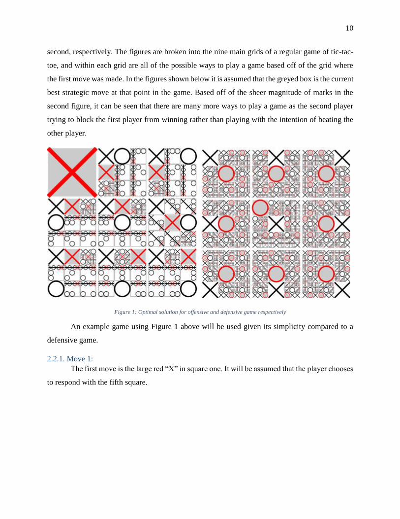
2.2.1. Move 1: The first move is the large red “X” in square one. It will be assumed that the player chooses
to respond with the fifth square.
11
Figure 2: First Move
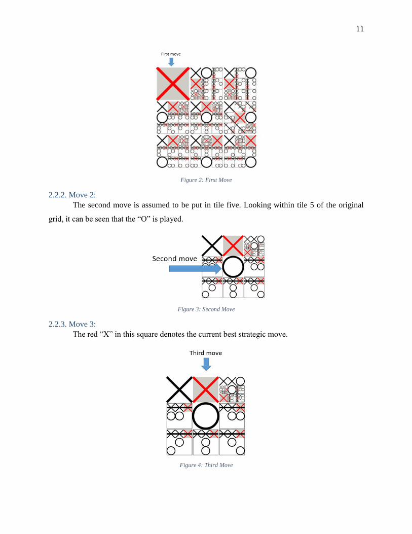
2.2.2. Move 2: The second move is assumed to be put in tile five. Looking within tile 5 of the original
grid, it can be seen that the “O” is played.
Figure 3: Second Move
2.2.3. Move 3: The red “X” in this square denotes the current best strategic move.
Figure 4: Third Move
12
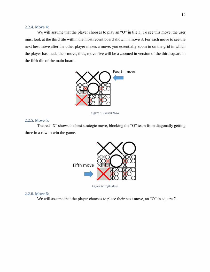
2.2.4. Move 4: We will assume that the player chooses to play an “O” in tile 3. To see this move, the user
must look at the third tile within the most recent board shown in move 3. For each move to see the
next best move after the other player makes a move, you essentially zoom in on the grid in which
the player has made their move, thus, move five will be a zoomed in version of the third square in
the fifth tile of the main board.
Figure 5: Fourth Move
2.2.5. Move 5: The red “X” shows the best strategic move, blocking the “O” team from diagonally getting
three in a row to win the game.
Figure 6: Fifth Move
2.2.6. Move 6: We will assume that the player chooses to place their next move, an “O” in square 7.
13
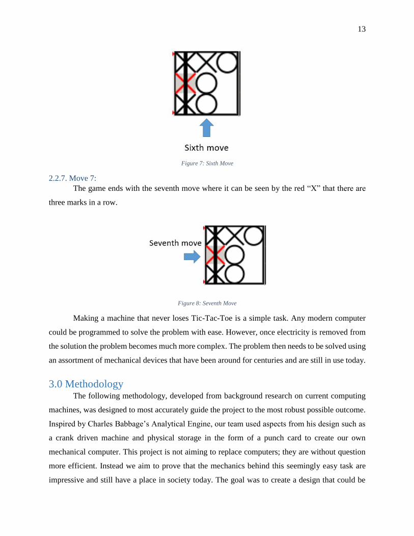
Figure 7: Sixth Move
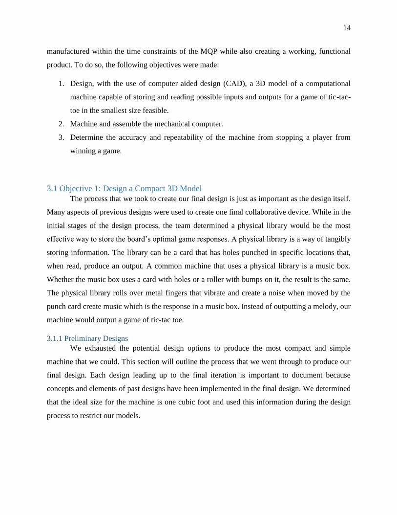
2.2.7. Move 7: The game ends with the seventh move where it can be seen by the red “X” that there are
three marks in a row.
Figure 8: Seventh Move
Making a machine that never loses Tic-Tac-Toe is a simple task. Any modern computer
could be programmed to solve the problem with ease. However, once electricity is removed from
the solution the problem becomes much more complex. The problem then needs to be solved using
an assortment of mechanical devices that have been around for centuries and are still in use today.
3.0 Methodology The following methodology, developed from background research on current computing
machines, was designed to most accurately guide the project to the most robust possible outcome.
Inspired by Charles Babbage’s Analytical Engine, our team used aspects from his design such as
a crank driven machine and physical storage in the form of a punch card to create our own
mechanical computer. This project is not aiming to replace computers; they are without question
more efficient. Instead we aim to prove that the mechanics behind this seemingly easy task are
impressive and still have a place in society today. The goal was to create a design that could be
14
manufactured within the time constraints of the MQP while also creating a working, functional
product. To do so, the following objectives were made:
1. Design, with the use of computer aided design (CAD), a 3D model of a computational
machine capable of storing and reading possible inputs and outputs for a game of tic-tac-
toe in the smallest size feasible.
2. Machine and assemble the mechanical computer.
3. Determine the accuracy and repeatability of the machine from stopping a player from
winning a game.
3.1 Objective 1: Design a Compact 3D Model
The process that we took to create our final design is just as important as the design itself.
Many aspects of previous designs were used to create one final collaborative device. While in the
initial stages of the design process, the team determined a physical library would be the most
effective way to store the board’s optimal game responses. A physical library is a way of tangibly
storing information. The library can be a card that has holes punched in specific locations that,
when read, produce an output. A common machine that uses a physical library is a music box.
Whether the music box uses a card with holes or a roller with bumps on it, the result is the same.
The physical library rolls over metal fingers that vibrate and create a noise when moved by the
punch card create music which is the response in a music box. Instead of outputting a melody, our
machine would output a game of tic-tac toe.
3.1.1 Preliminary Designs
We exhausted the potential design options to produce the most compact and simple
machine that we could. This section will outline the process that we went through to produce our
final design. Each design leading up to the final iteration is important to document because
concepts and elements of past designs have been implemented in the final design. We determined
that the ideal size for the machine is one cubic foot and used this information during the design
process to restrict our models.
15
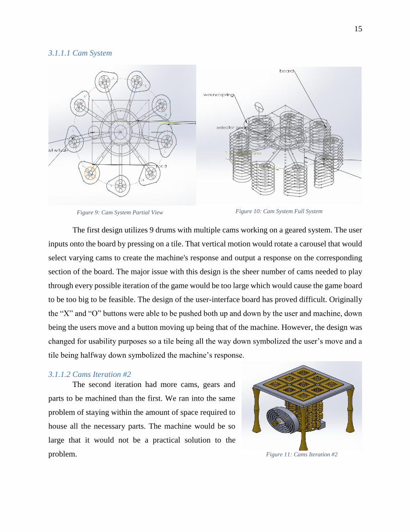
3.1.1.1 Cam System
The first design utilizes 9 drums with multiple cams working on a geared system. The user
inputs onto the board by pressing on a tile. That vertical motion would rotate a carousel that would
select varying cams to create the machine's response and output a response on the corresponding
section of the board. The major issue with this design is the sheer number of cams needed to play
through every possible iteration of the game would be too large which would cause the game board
to be too big to be feasible. The design of the user-interface board has proved difficult. Originally
the “X” and “O” buttons were able to be pushed both up and down by the user and machine, down
being the users move and a button moving up being that of the machine. However, the design was
changed for usability purposes so a tile being all the way down symbolized the user’s move and a
tile being halfway down symbolized the machine’s response.
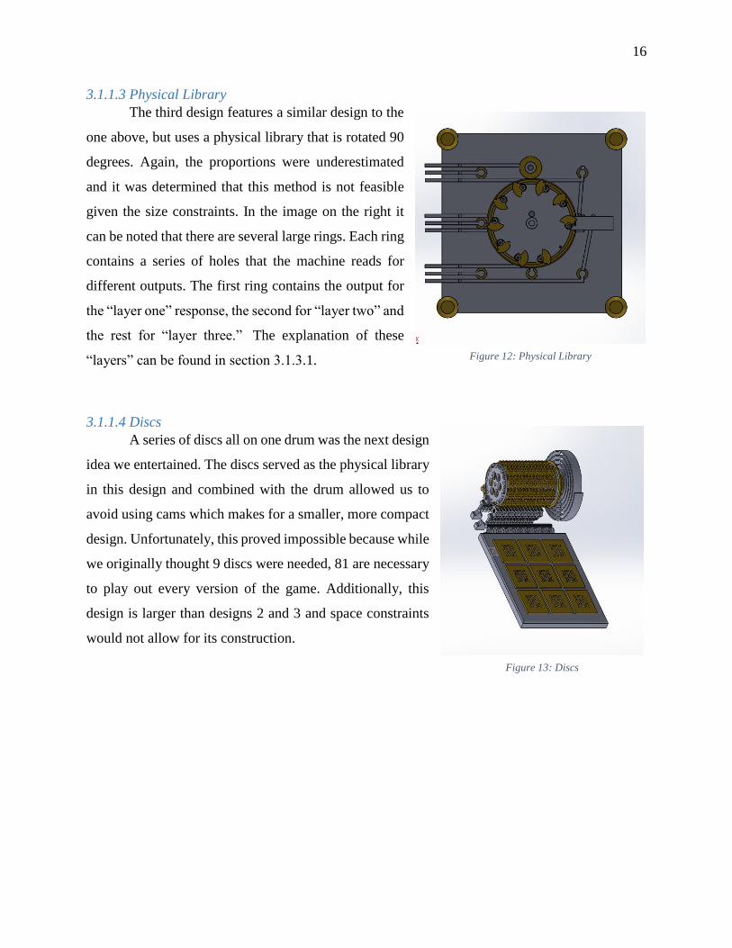
3.1.1.2 Cams Iteration #2
The second iteration had more cams, gears and
parts to be machined than the first. We ran into the same
problem of staying within the amount of space required to
house all the necessary parts. The machine would be so
large that it would not be a practical solution to the
problem.
Figure 9: Cam System Partial View Figure 10: Cam System Full System
Figure 11: Cams Iteration #2
16
3.1.1.3 Physical Library
The third design features a similar design to the
one above, but uses a physical library that is rotated 90
degrees. Again, the proportions were underestimated
and it was determined that this method is not feasible
given the size constraints. In the image on the right it
can be noted that there are several large rings. Each ring
contains a series of holes that the machine reads for
different outputs. The first ring contains the output for
the “layer one” response, the second for “layer two” and
the rest for “layer three.” The explanation of these
“layers” can be found in section 3.1.3.1.
3.1.1.4 Discs
A series of discs all on one drum was the next design
idea we entertained. The discs served as the physical library
in this design and combined with the drum allowed us to
avoid using cams which makes for a smaller, more compact
design. Unfortunately, this proved impossible because while
we originally thought 9 discs were needed, 81 are necessary
to play out every version of the game. Additionally, this
design is larger than designs 2 and 3 and space constraints
would not allow for its construction.
Figure 12: Physical Library
Figure 13: Discs
17
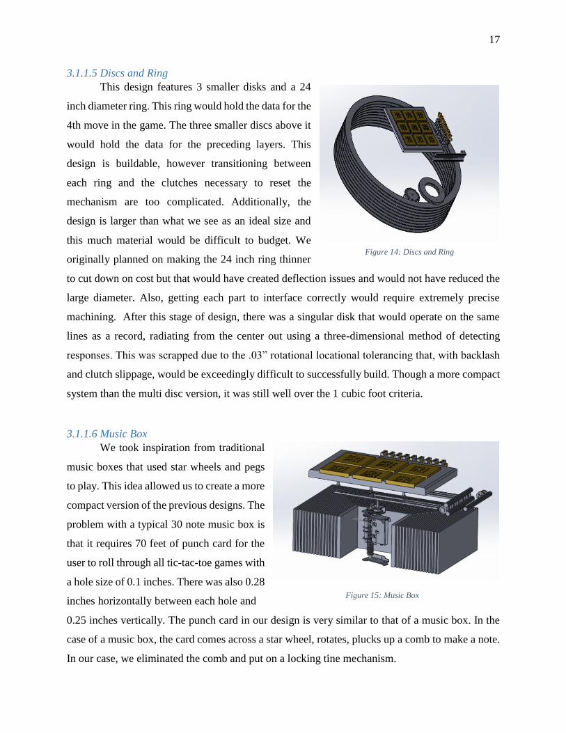
3.1.1.5 Discs and Ring
This design features 3 smaller disks and a 24
inch diameter ring. This ring would hold the data for the
4th move in the game. The three smaller discs above it
would hold the data for the preceding layers. This
design is buildable, however transitioning between
each ring and the clutches necessary to reset the
mechanism are too complicated. Additionally, the
design is larger than what we see as an ideal size and
this much material would be difficult to budget. We
originally planned on making the 24 inch ring thinner
to cut down on cost but that would have created deflection issues and would not have reduced the
large diameter. Also, getting each part to interface correctly would require extremely precise
machining. After this stage of design, there was a singular disk that would operate on the same
lines as a record, radiating from the center out using a three-dimensional method of detecting
responses. This was scrapped due to the .03” rotational locational tolerancing that, with backlash
and clutch slippage, would be exceedingly difficult to successfully build. Though a more compact
system than the multi disc version, it was still well over the 1 cubic foot criteria.
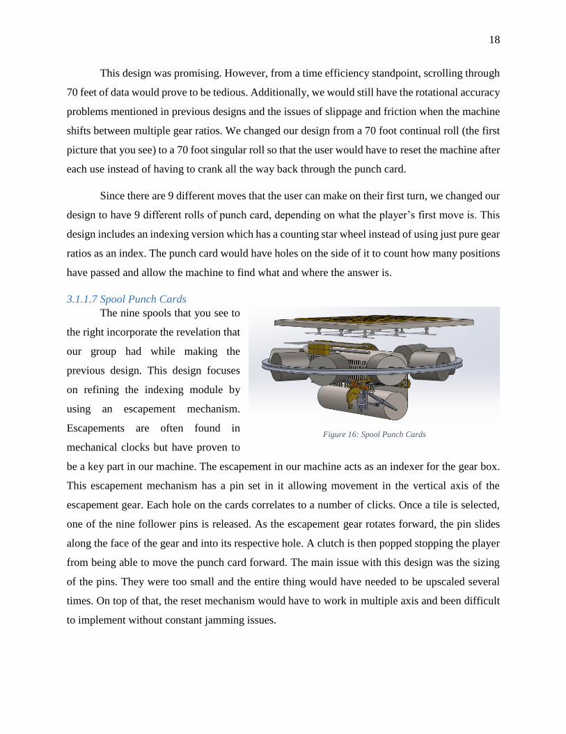
3.1.1.6 Music Box
We took inspiration from traditional
music boxes that used star wheels and pegs
to play. This idea allowed us to create a more
compact version of the previous designs. The
problem with a typical 30 note music box is
that it requires 70 feet of punch card for the
user to roll through all tic-tac-toe games with
a hole size of 0.1 inches. There was also 0.28
inches horizontally between each hole and
0.25 inches vertically. The punch card in our design is very similar to that of a music box. In the
case of a music box, the card comes across a star wheel, rotates, plucks up a comb to make a note.
In our case, we eliminated the comb and put on a locking tine mechanism.
Figure 14: Discs and Ring
Figure 15: Music Box
18
This design was promising. However, from a time efficiency standpoint, scrolling through
70 feet of data would prove to be tedious. Additionally, we would still have the rotational accuracy
problems mentioned in previous designs and the issues of slippage and friction when the machine
shifts between multiple gear ratios. We changed our design from a 70 foot continual roll (the first
picture that you see) to a 70 foot singular roll so that the user would have to reset the machine after
each use instead of having to crank all the way back through the punch card.
Since there are 9 different moves that the user can make on their first turn, we changed our
design to have 9 different rolls of punch card, depending on what the player’s first move is. This
design includes an indexing version which has a counting star wheel instead of using just pure gear
ratios as an index. The punch card would have holes on the side of it to count how many positions
have passed and allow the machine to find what and where the answer is.
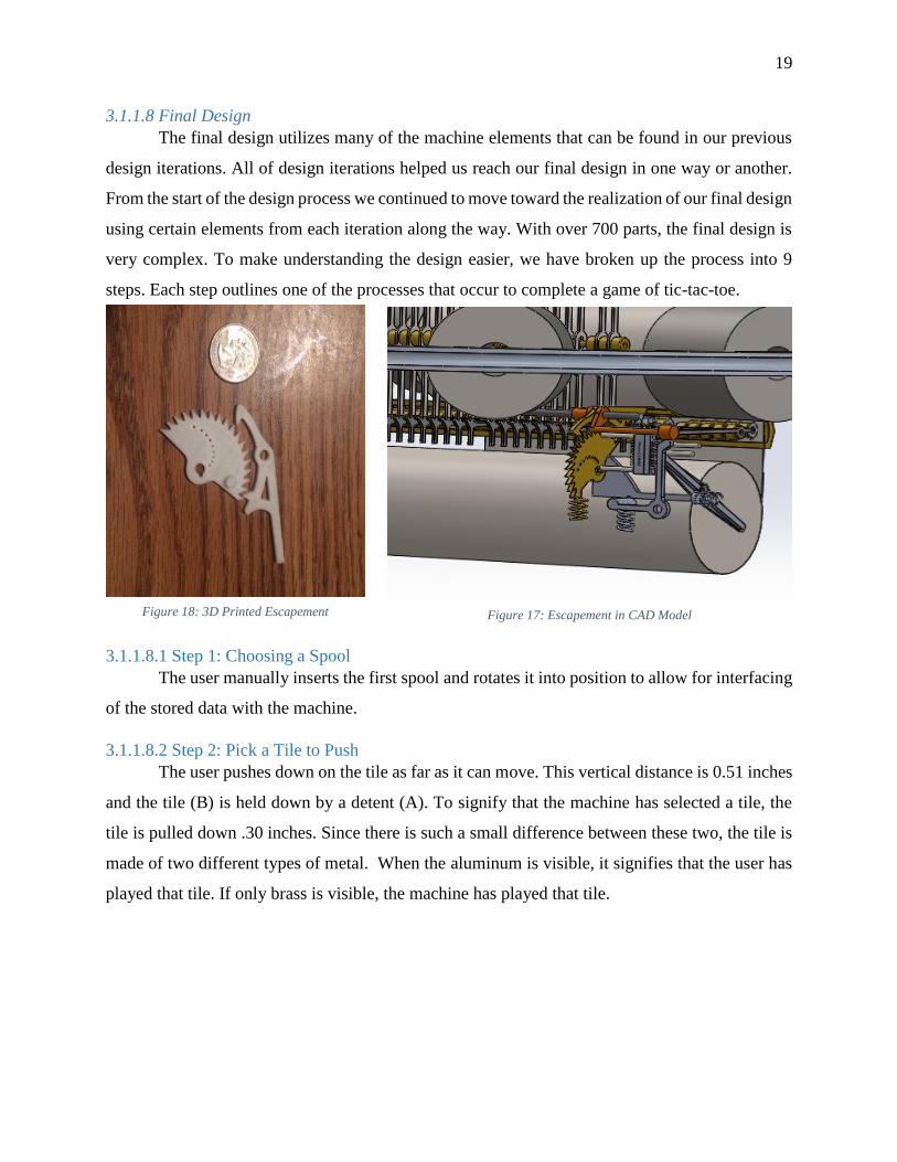
3.1.1.7 Spool Punch Cards
The nine spools that you see to
the right incorporate the revelation that
our group had while making the
previous design. This design focuses
on refining the indexing module by
using an escapement mechanism.
Escapements are often found in
mechanical clocks but have proven to
be a key part in our machine. The escapement in our machine acts as an indexer for the gear box.
This escapement mechanism has a pin set in it allowing movement in the vertical axis of the
escapement gear. Each hole on the cards correlates to a number of clicks. Once a tile is selected,
one of the nine follower pins is released. As the escapement gear rotates forward, the pin slides
along the face of the gear and into its respective hole. A clutch is then popped stopping the player
from being able to move the punch card forward. The main issue with this design was the sizing
of the pins. They were too small and the entire thing would have needed to be upscaled several
times. On top of that, the reset mechanism would have to work in multiple axis and been difficult
to implement without constant jamming issues.
Figure 16: Spool Punch Cards
19
3.1.1.8 Final Design
The final design utilizes many of the machine elements that can be found in our previous
design iterations. All of design iterations helped us reach our final design in one way or another.
From the start of the design process we continued to move toward the realization of our final design
using certain elements from each iteration along the way. With over 700 parts, the final design is
very complex. To make understanding the design easier, we have broken up the process into 9
steps. Each step outlines one of the processes that occur to complete a game of tic-tac-toe.
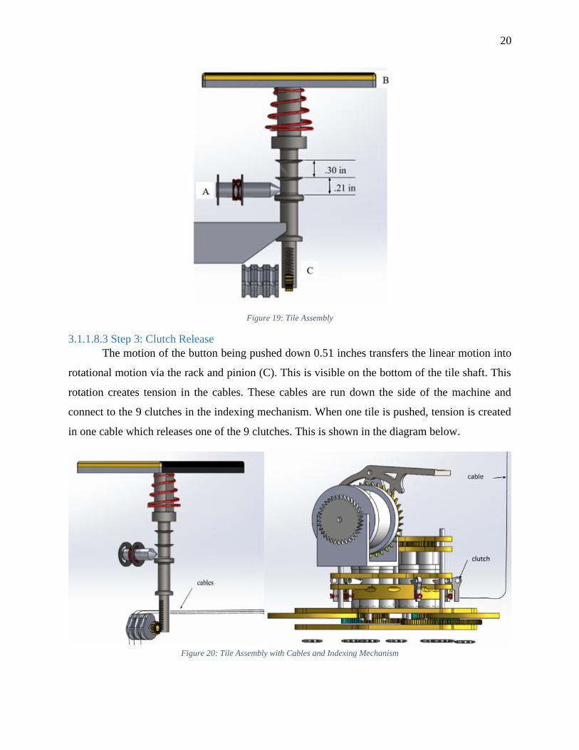
3.1.1.8.1 Step 1: Choosing a Spool
The user manually inserts the first spool and rotates it into position to allow for interfacing
of the stored data with the machine.
3.1.1.8.2 Step 2: Pick a Tile to Push
The user pushes down on the tile as far as it can move. This vertical distance is 0.51 inches
and the tile (B) is held down by a detent (A). To signify that the machine has selected a tile, the
tile is pulled down .30 inches. Since there is such a small difference between these two, the tile is
made of two different types of metal. When the aluminum is visible, it signifies that the user has
played that tile. If only brass is visible, the machine has played that tile.
Figure 18: 3D Printed Escapement Figure 17: Escapement in CAD Model
20
Figure 19: Tile Assembly
3.1.1.8.3 Step 3: Clutch Release
The motion of the button being pushed down 0.51 inches transfers the linear motion into
rotational motion via the rack and pinion (C). This is visible on the bottom of the tile shaft. This
rotation creates tension in the cables. These cables are run down the side of the machine and
connect to the 9 clutches in the indexing mechanism. When one tile is pushed, tension is created
in one cable which releases one of the 9 clutches. This is shown in the diagram below.
Figure 20: Tile Assembly with Cables and Indexing Mechanism
21
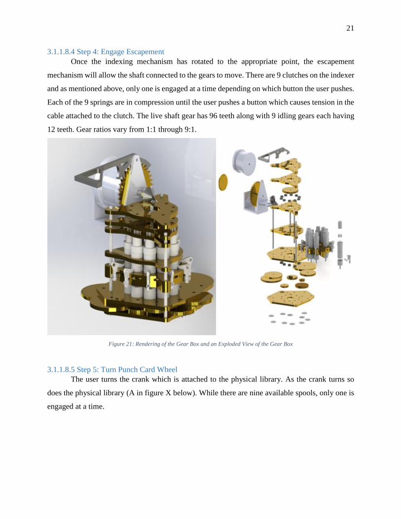
3.1.1.8.4 Step 4: Engage Escapement
Once the indexing mechanism has rotated to the appropriate point, the escapement
mechanism will allow the shaft connected to the gears to move. There are 9 clutches on the indexer
and as mentioned above, only one is engaged at a time depending on which button the user pushes.
Each of the 9 springs are in compression until the user pushes a button which causes tension in the
cable attached to the clutch. The live shaft gear has 96 teeth along with 9 idling gears each having
12 teeth. Gear ratios vary from 1:1 through 9:1.
Figure 21: Rendering of the Gear Box and an Exploded View of the Gear Box
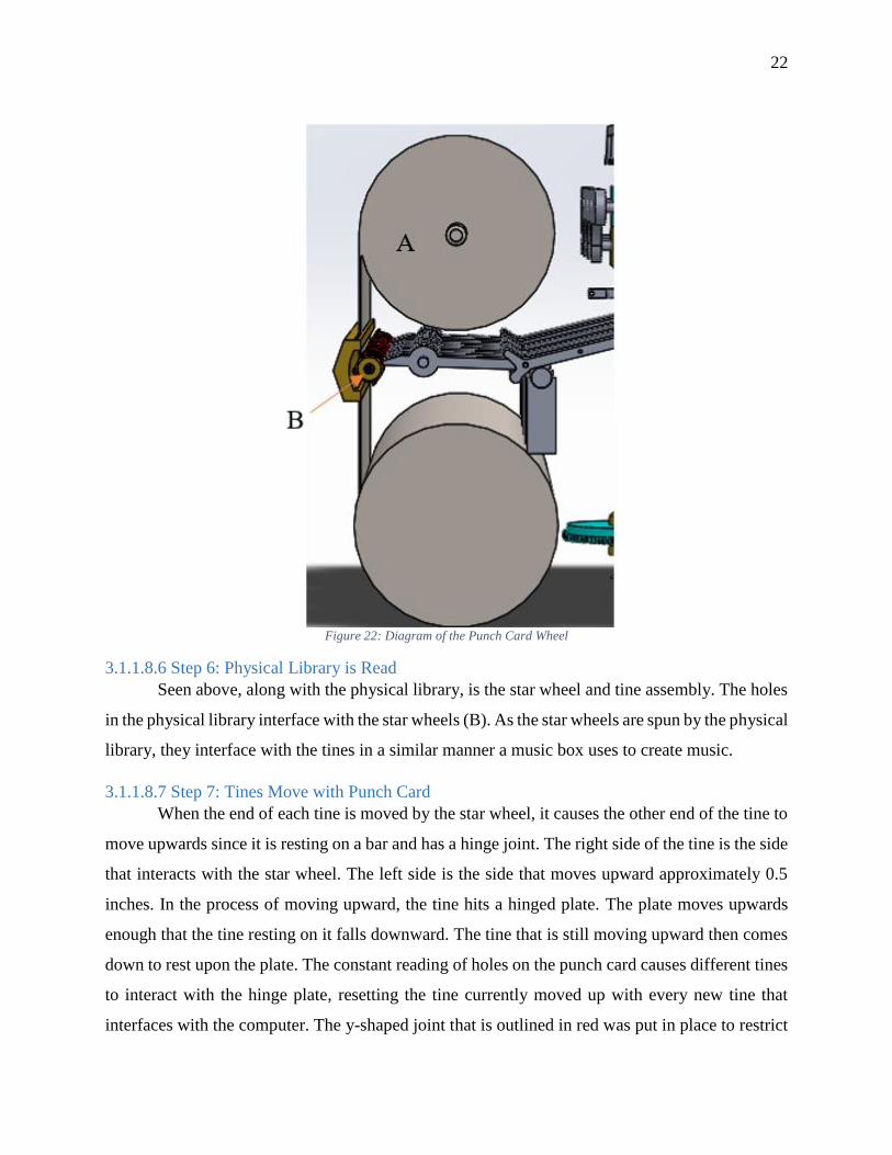
3.1.1.8.5 Step 5: Turn Punch Card Wheel
The user turns the crank which is attached to the physical library. As the crank turns so
does the physical library (A in figure X below). While there are nine available spools, only one is
engaged at a time.
22
Figure 22: Diagram of the Punch Card Wheel
3.1.1.8.6 Step 6: Physical Library is Read
Seen above, along with the physical library, is the star wheel and tine assembly. The holes
in the physical library interface with the star wheels (B). As the star wheels are spun by the physical
library, they interface with the tines in a similar manner a music box uses to create music.
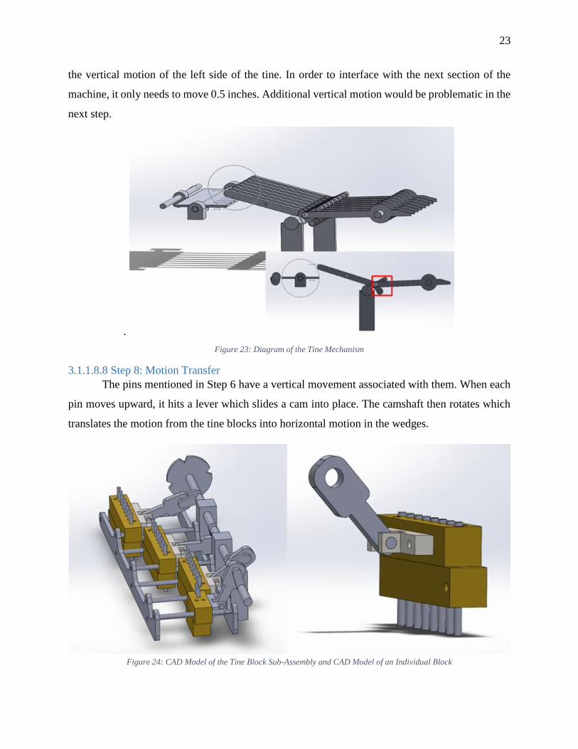
3.1.1.8.7 Step 7: Tines Move with Punch Card
When the end of each tine is moved by the star wheel, it causes the other end of the tine to
move upwards since it is resting on a bar and has a hinge joint. The right side of the tine is the side
that interacts with the star wheel. The left side is the side that moves upward approximately 0.5
inches. In the process of moving upward, the tine hits a hinged plate. The plate moves upwards
enough that the tine resting on it falls downward. The tine that is still moving upward then comes
down to rest upon the plate. The constant reading of holes on the punch card causes different tines
to interact with the hinge plate, resetting the tine currently moved up with every new tine that
interfaces with the computer. The y-shaped joint that is outlined in red was put in place to restrict
23
the vertical motion of the left side of the tine. In order to interface with the next section of the
machine, it only needs to move 0.5 inches. Additional vertical motion would be problematic in the
next step.
.
Figure 23: Diagram of the Tine Mechanism
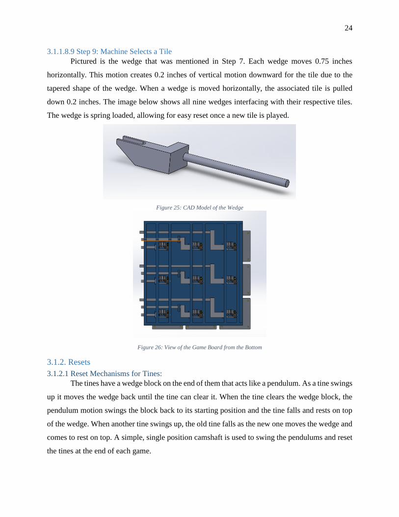
3.1.1.8.8 Step 8: Motion Transfer
The pins mentioned in Step 6 have a vertical movement associated with them. When each
pin moves upward, it hits a lever which slides a cam into place. The camshaft then rotates which
translates the motion from the tine blocks into horizontal motion in the wedges.
Figure 24: CAD Model of the Tine Block Sub-Assembly and CAD Model of an Individual Block
24
3.1.1.8.9 Step 9: Machine Selects a Tile
Pictured is the wedge that was mentioned in Step 7. Each wedge moves 0.75 inches
horizontally. This motion creates 0.2 inches of vertical motion downward for the tile due to the
tapered shape of the wedge. When a wedge is moved horizontally, the associated tile is pulled
down 0.2 inches. The image below shows all nine wedges interfacing with their respective tiles.
The wedge is spring loaded, allowing for easy reset once a new tile is played.
Figure 25: CAD Model of the Wedge
Figure 26: View of the Game Board from the Bottom
3.1.2. Resets
3.1.2.1 Reset Mechanisms for Tines:
The tines have a wedge block on the end of them that acts like a pendulum. As a tine swings
up it moves the wedge back until the tine can clear it. When the tine clears the wedge block, the
pendulum motion swings the block back to its starting position and the tine falls and rests on top
of the wedge. When another tine swings up, the old tine falls as the new one moves the wedge and
comes to rest on top. A simple, single position camshaft is used to swing the pendulums and reset
the tines at the end of each game.
25
3.1.2.2 Gear Box Reset:
The gear box has a clutch reset that encompasses all of the clutches. The plate is pulled
upward and disengages all of the clutches in the process. These clutches need to be reset between
each round of the game in order to clear old inputs and put machine on track to read the next set
of plays on the physical memory.
3.1.2.3 Tile Reset:
Each of the tiles is held down with a detent. All of the detents are spring loaded forward
and attached to a bar in the back. After the game, the user would simply need to pull the bar back
allowing the spring loaded tiles to return to their initial positions.
3.1.3 Calculations and Tolerancing
3.1.3.1 Creating a Numerical System of Data
In order to create a series of logical inputs and outputs i.e. physical memory, that the
machine would be capable of reading, a game of tic-tac-toe needed to be represented in a matrix
format. Changing the “X” and “O” inputs and outputs to be numbers based off of location on a
grid allows for a better mapping of potential moves.
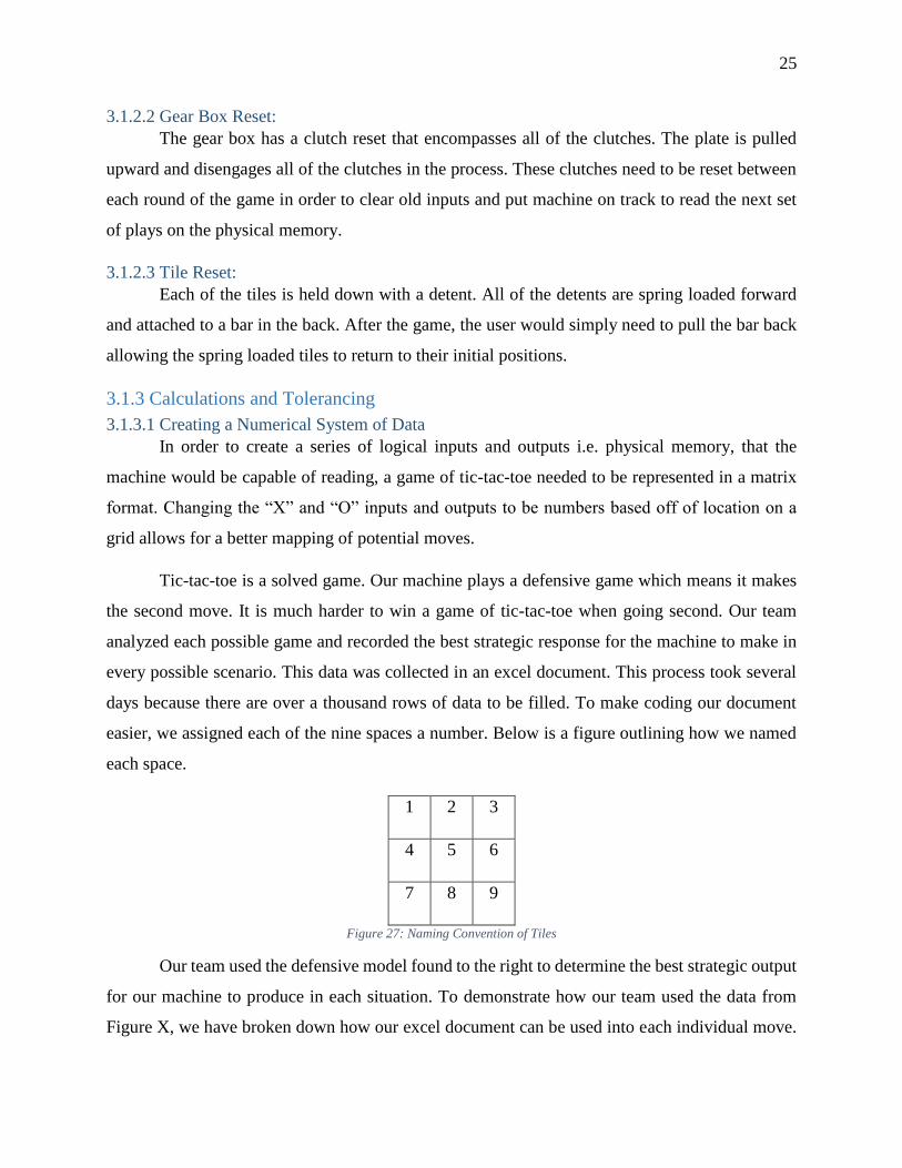
Tic-tac-toe is a solved game. Our machine plays a defensive game which means it makes
the second move. It is much harder to win a game of tic-tac-toe when going second. Our team
analyzed each possible game and recorded the best strategic response for the machine to make in
every possible scenario. This data was collected in an excel document. This process took several
days because there are over a thousand rows of data to be filled. To make coding our document
easier, we assigned each of the nine spaces a number. Below is a figure outlining how we named
each space.
1 2 3
4 5 6
7 8 9
Figure 27: Naming Convention of Tiles
Our team used the defensive model found to the right to determine the best strategic output
for our machine to produce in each situation. To demonstrate how our team used the data from
Figure X, we have broken down how our excel document can be used into each individual move.
26
The example will outline a game in which the user selects tile 1 as their first move, tile 4
for their second move, tile 3 for their third move, and 8 for their final move. The user’s tile choice
and the computer's response to that choice are called a “layer” in this document. For example, the
user’s first move and the computer's response to that are called the “1st Layer” in this
document. The “X” represents the user and the “O” represents the computer.
Figure 28: Optimal Strategy to play a Defensive Game of Tic-Tac-Toe
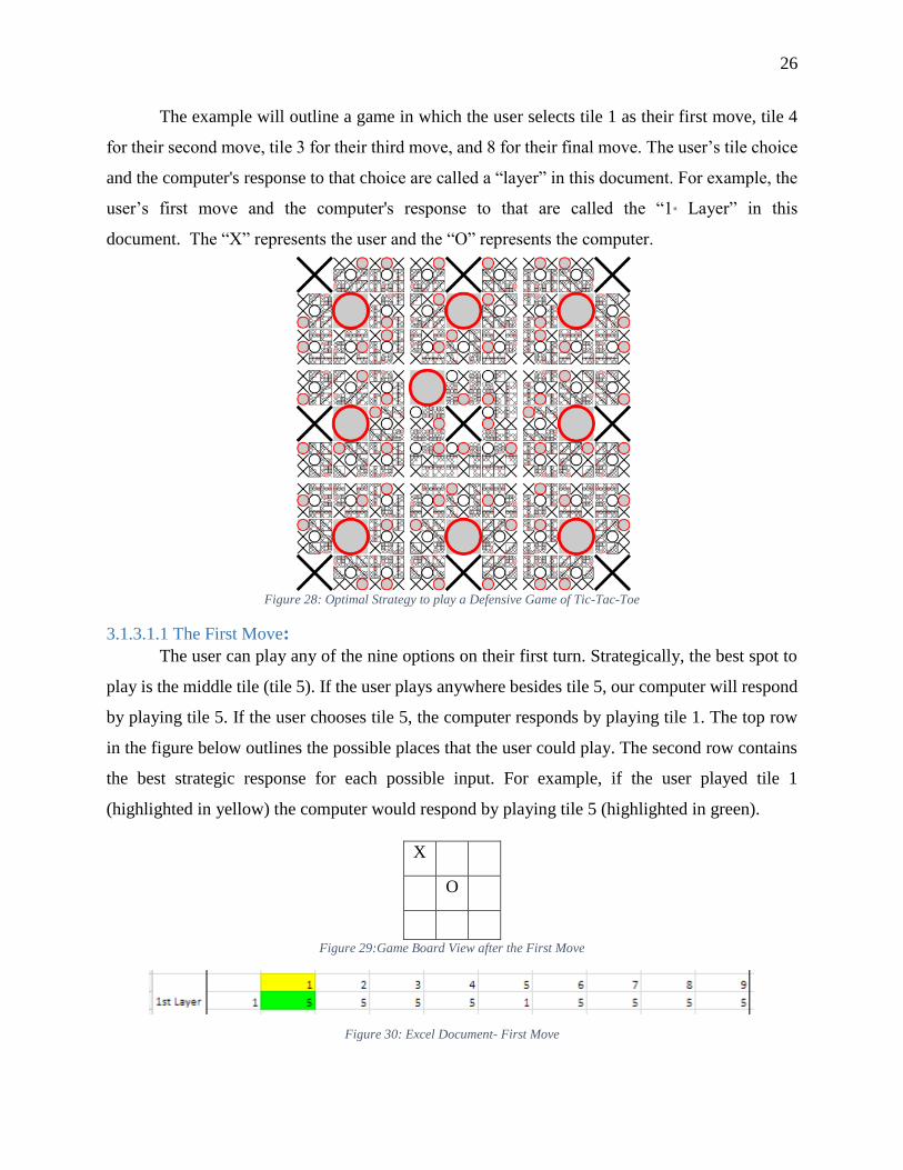
3.1.3.1.1 The First Move:
The user can play any of the nine options on their first turn. Strategically, the best spot to
play is the middle tile (tile 5). If the user plays anywhere besides tile 5, our computer will respond
by playing tile 5. If the user chooses tile 5, the computer responds by playing tile 1. The top row
in the figure below outlines the possible places that the user could play. The second row contains
the best strategic response for each possible input. For example, if the user played tile 1
(highlighted in yellow) the computer would respond by playing tile 5 (highlighted in green).
X
O
O
Figure 29:Game Board View after the First Move
Figure 30: Excel Document- First Move
27
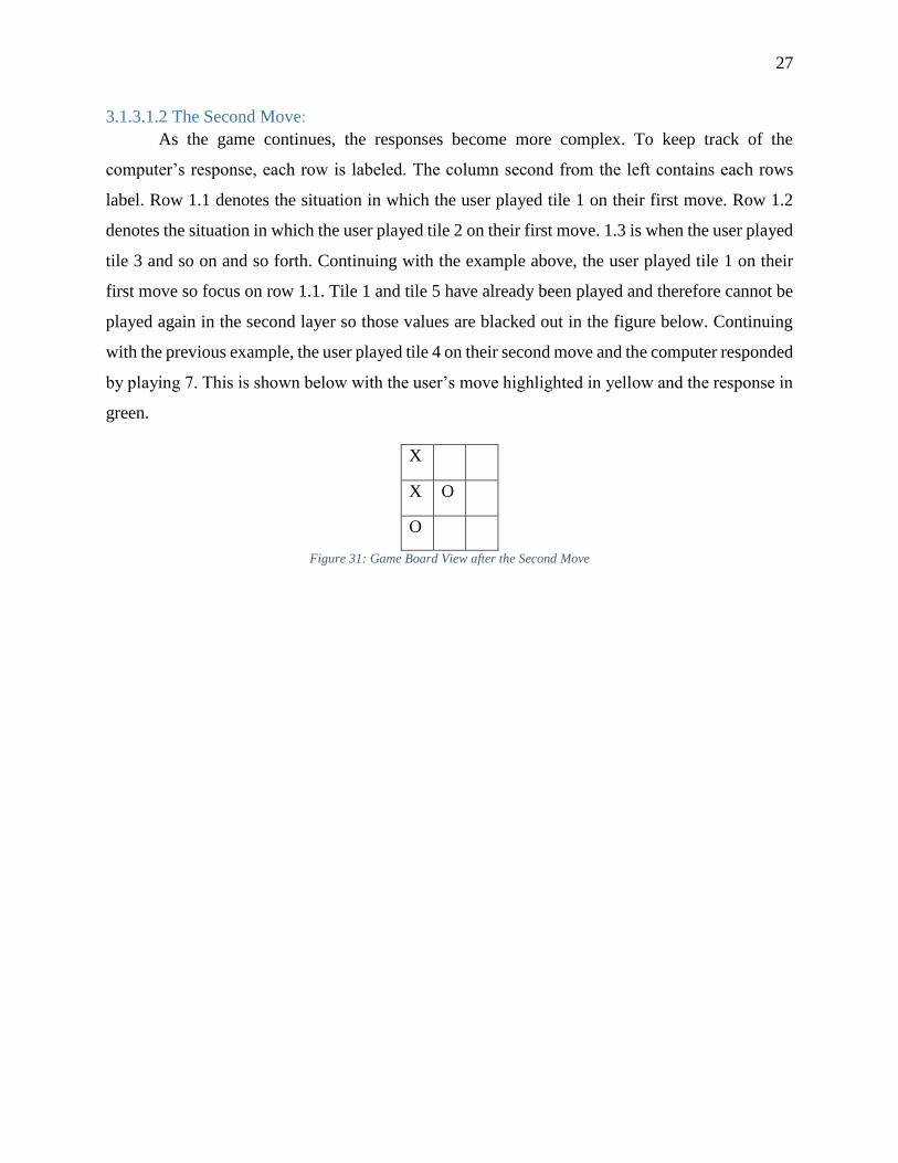
3.1.3.1.2 The Second Move:
As the game continues, the responses become more complex. To keep track of the
computer’s response, each row is labeled. The column second from the left contains each rows
label. Row 1.1 denotes the situation in which the user played tile 1 on their first move. Row 1.2
denotes the situation in which the user played tile 2 on their first move. 1.3 is when the user played
tile 3 and so on and so forth. Continuing with the example above, the user played tile 1 on their
first move so focus on row 1.1. Tile 1 and tile 5 have already been played and therefore cannot be
played again in the second layer so those values are blacked out in the figure below. Continuing
with the previous example, the user played tile 4 on their second move and the computer responded
by playing 7. This is shown below with the user’s move highlighted in yellow and the response in
green.
X
O
X O
O
Figure 31: Game Board View after the Second Move
28
Figure 32: Excel Document- Second Move
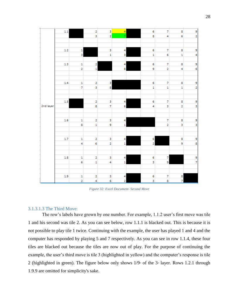
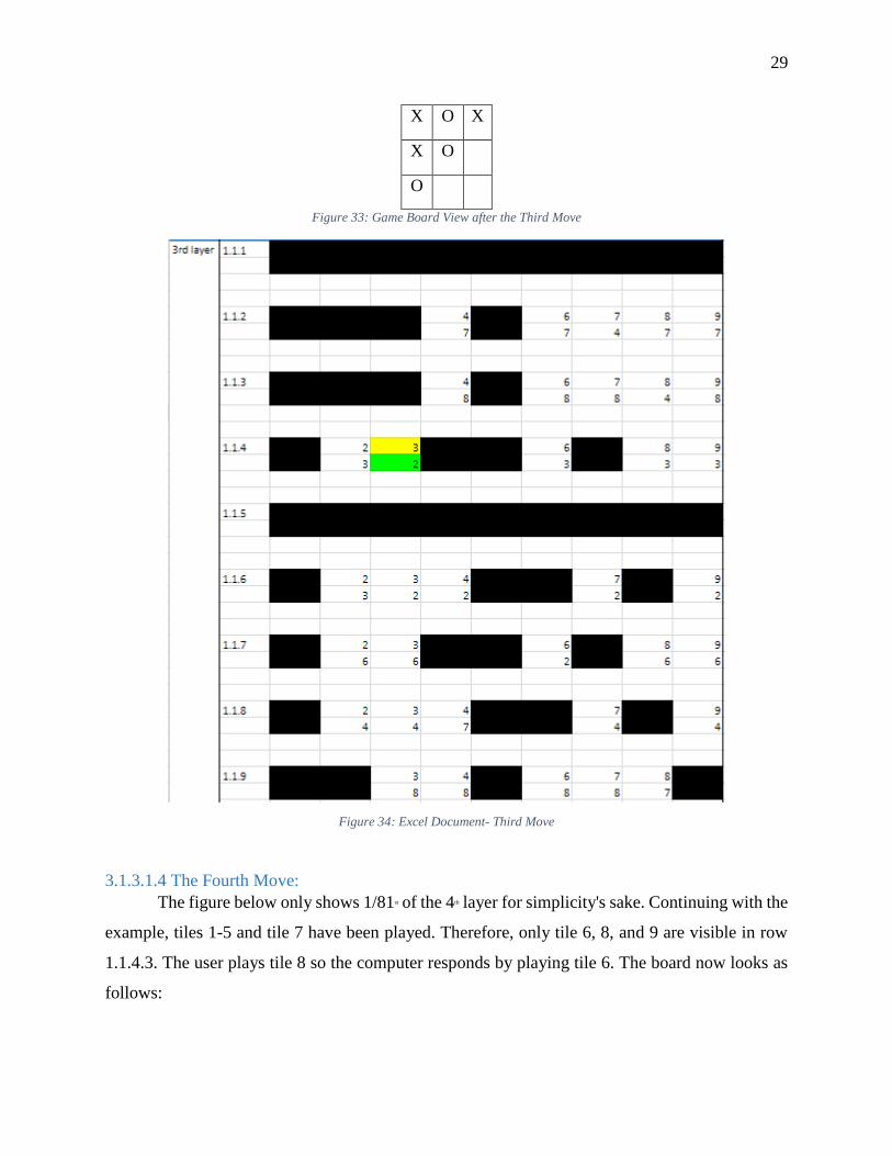
3.1.3.1.3 The Third Move:
The row’s labels have grown by one number. For example, 1.1.2 user’s first move was tile
1 and his second was tile 2. As you can see below, row 1.1.1 is blacked out. This is because it is
not possible to play tile 1 twice. Continuing with the example, the user has played 1 and 4 and the
computer has responded by playing 5 and 7 respectively. As you can see in row 1.1.4, these four
tiles are blacked out because the tiles are now out of play. For the purpose of continuing the
example, the user’s third move is tile 3 (highlighted in yellow) and the computer’s response is tile
2 (highlighted in green). The figure below only shows 1/9th of the 3rd layer. Rows 1.2.1 through
1.9.9 are omitted for simplicity's sake.
29
X O X
X O
O
Figure 33: Game Board View after the Third Move
Figure 34: Excel Document- Third Move
3.1.3.1.4 The Fourth Move:
The figure below only shows 1/81st of the 4th layer for simplicity's sake. Continuing with the
example, tiles 1-5 and tile 7 have been played. Therefore, only tile 6, 8, and 9 are visible in row
1.1.4.3. The user plays tile 8 so the computer responds by playing tile 6. The board now looks as
follows:

30
X O X
X O O
O X
Figure 35: Game Board View after the Fourth Move
The user could play a fifth tile; however, it would not change the outcome of the game.
The result is a draw.
Figure 36: Excel Document- Fourth Move
3.1.3.2 Binary Format of Numerical Data Compilation
The original system that we created to keep track of data was a digital system. However,
the punch card design runs on a binary system. The digital system allowed us to know what the
proper response for the machine was but needed to be converted into a binary system so the data
could then be converted into Cartesian coordinates and input into SolidWorks. Is there a hole or
isn’t there? The data outlined in the previous section had to be changed from a digital format into
a binary one. To achieve this, we created a series of excel documents. There are 9 excel documents,
one for each of the tiles that the user can select as his first move. An example of this document is
shown below.
31
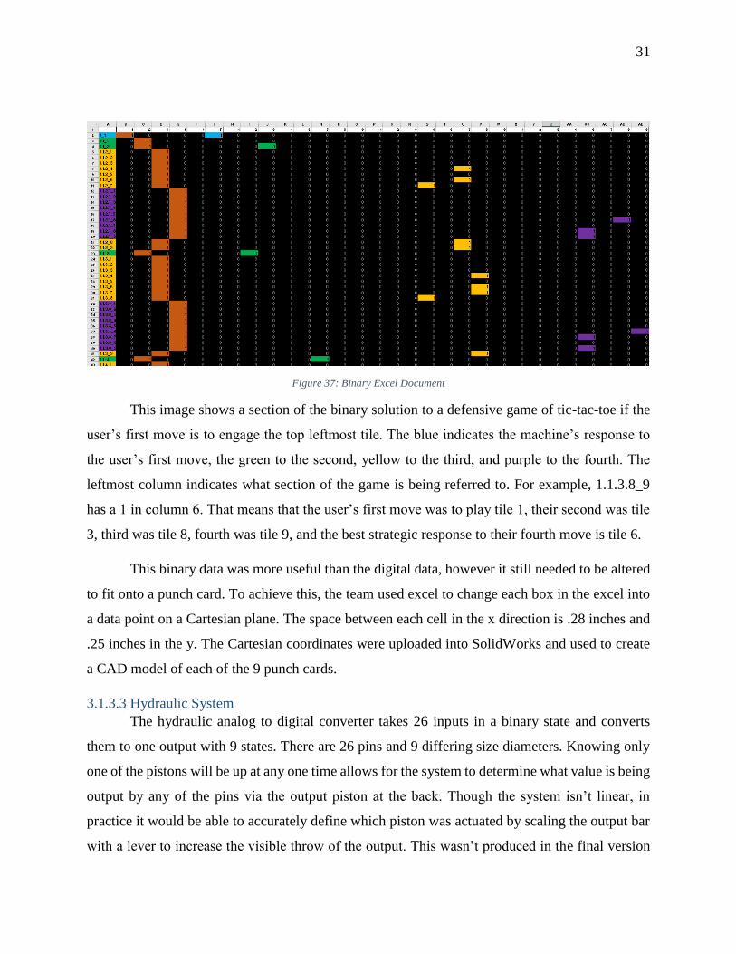
Figure 37: Binary Excel Document
This image shows a section of the binary solution to a defensive game of tic-tac-toe if the
user’s first move is to engage the top leftmost tile. The blue indicates the machine’s response to
the user’s first move, the green to the second, yellow to the third, and purple to the fourth. The
leftmost column indicates what section of the game is being referred to. For example, 1.1.3.8_9
has a 1 in column 6. That means that the user’s first move was to play tile 1, their second was tile
3, third was tile 8, fourth was tile 9, and the best strategic response to their fourth move is tile 6.
This binary data was more useful than the digital data, however it still needed to be altered
to fit onto a punch card. To achieve this, the team used excel to change each box in the excel into
a data point on a Cartesian plane. The space between each cell in the x direction is .28 inches and
.25 inches in the y. The Cartesian coordinates were uploaded into SolidWorks and used to create
a CAD model of each of the 9 punch cards.
3.1.3.3 Hydraulic System
The hydraulic analog to digital converter takes 26 inputs in a binary state and converts
them to one output with 9 states. There are 26 pins and 9 differing size diameters. Knowing only
one of the pistons will be up at any one time allows for the system to determine what value is being
output by any of the pins via the output piston at the back. Though the system isn’t linear, in
practice it would be able to accurately define which piston was actuated by scaling the output bar
with a lever to increase the visible throw of the output. This wasn’t produced in the final version
32
due to the manufacturing time involved in making a working system and other manufacturing
issues. The system was reverted to a bar linkage system similar to the one shown previously.
3.1.3.4 Tolerancing
In order for each part to properly interface, it is important that there is enough tolerancing
to avoid problems such as shearing and travel restriction. Considerations must be made for the
slight variances in size caused by machining. In general, the average rule of thumb was to leave a
five to ten thousandth of an inch clearance on sliding parts during the design process. In the case
of diametrical interfaces, or a pin riding inside of a bore, it is essential that the size of the pin and
the hole are not the same size as friction would limit the part from moving. While it is important
to allow for friction tolerancing, it is also important to limit travel. For example, the spring tab
engages in vertical motion when the playing tile is pressed on and the lower portion of the tab has
a rack on it that interfaces with a pinion. The hole that the spring tab travels through needs to have
enough tolerance to allow for the vertical displacement of being pressed, however motion must be
limited in order to keep the rack and pinion engaged without having too much room to travel
radially. For reasons such as the example listed above, tolerancing between parts were restricted
as much as possible while still mitigating friction. The tolerance stack up created in the design
process would allow for optimal movement with minimal frictional errors.
3.2 Objective 2: Machining and Assembly
3.2.1 Machining Process
The majority of parts used in the final assembly were built in the machine shops of Higgins
and Washburn shops on WPI’s campus. Other parts that could not be made at WPI were outsourced
to a contact at Massachusetts Institute of Technology (MIT) as a means to have parts cut with a
water jet. Other standard parts (screws, etc.) and stock were ordered through McMaster Carr. In
total, approximately 700 parts were used in the making of the computer, 500 of which were made
in WPI facilities. The materials used to manufacture parts was primarily brass, aluminum, and
4140 steel.
3.2.1.1 Manual Machining
A majority of the parts that make up our tic-tac-toe board were manufactured manually in
the Higgins machine shop. Many of the parts we designed had only one or two copies needed for
the construction of the board therefore, it was quicker to manually machine these parts than taking
the time to write the program for the Computer Numerical Control (CNC) machining. The vertical
33
mills in the Higgins shop were utilized for machining most of the parts that were made for the
board. All of the rods that needed to be turned on a lathe were made using the manual lathe in the
Higgins shop. All of the gears in our board were cut manual in Higgins using an Ellis dividing
head. The dividing head allows the machinist to look up in a chart the amount of rotations needed
to cut the correct number of teeth in a gear as well as the correct plate. The teeth of the gears were
first cut using the horizontal mill and then parted off using the lathe.
3.2.1.2 Computer-Numerical Control Machining
The Computer-Numerical Control (CNC) machining was done using the Mini Mill and ST-
10 (lathe). The allure of using CNC for machining is mass production and repeatability. For this
reason, parts requiring high volumes were CNC machined. As there are nine tiles in a game of tic-
tac-toe, there were at minimum usually nine parts of any given feature needed that interfaced with
the tiles. For this reason, it was quicker to take a drawing for a part out of the SolidWorks file for
the project and import it to Esprit, a computer aided machining (CAM) software. Once in Esprit,
the part needed to be programmed once to be cut and the same program could be repeated on
multiple parts with the only down time in between machining being entering new parts and re-
probing surfaces. Esprit allows for a complete simulation of the part to be machined, a useful tactic
to avoid potential collisions and a chance to review that all of the programming was inputted
correctly. Feeds and speeds do not need to be manually entered into the machine during use, merely
included in the program being created for the machining process beforehand.
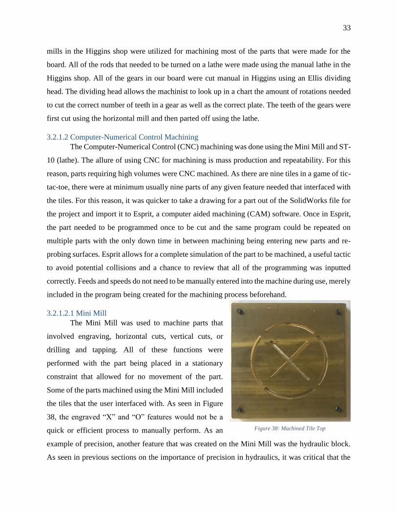
3.2.1.2.1 Mini Mill
The Mini Mill was used to machine parts that
involved engraving, horizontal cuts, vertical cuts, or
drilling and tapping. All of these functions were
performed with the part being placed in a stationary
constraint that allowed for no movement of the part.
Some of the parts machined using the Mini Mill included
the tiles that the user interfaced with. As seen in Figure
38, the engraved “X” and “O” features would not be a
quick or efficient process to manually perform. As an
example of precision, another feature that was created on the Mini Mill was the hydraulic block.
As seen in previous sections on the importance of precision in hydraulics, it was critical that the
Figure 38: Machined Tile Top
34
diameters of each hole were exact. The process involved milling out the base for all of the piston
holes followed by the milling and reaming of each individual hole.
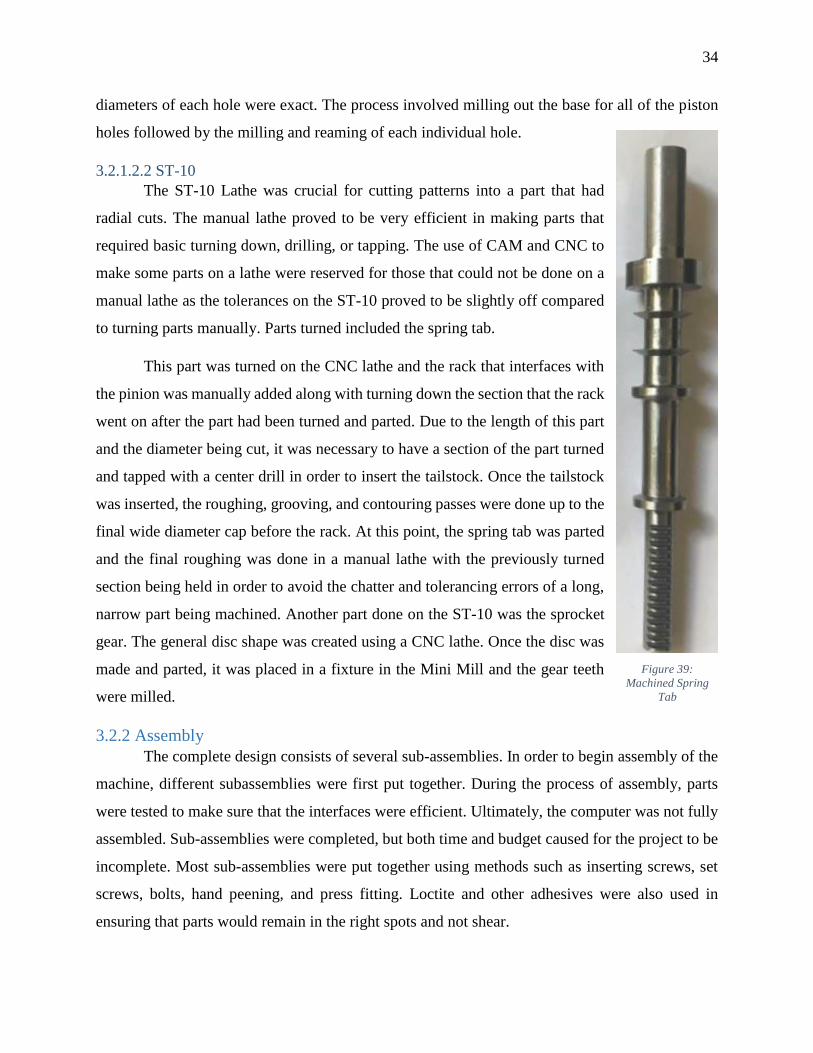
3.2.1.2.2 ST-10
The ST-10 Lathe was crucial for cutting patterns into a part that had
radial cuts. The manual lathe proved to be very efficient in making parts that
required basic turning down, drilling, or tapping. The use of CAM and CNC to
make some parts on a lathe were reserved for those that could not be done on a
manual lathe as the tolerances on the ST-10 proved to be slightly off compared
to turning parts manually. Parts turned included the spring tab.
This part was turned on the CNC lathe and the rack that interfaces with
the pinion was manually added along with turning down the section that the rack
went on after the part had been turned and parted. Due to the length of this part
and the diameter being cut, it was necessary to have a section of the part turned
and tapped with a center drill in order to insert the tailstock. Once the tailstock
was inserted, the roughing, grooving, and contouring passes were done up to the
final wide diameter cap before the rack. At this point, the spring tab was parted
and the final roughing was done in a manual lathe with the previously turned
section being held in order to avoid the chatter and tolerancing errors of a long,
narrow part being machined. Another part done on the ST-10 was the sprocket
gear. The general disc shape was created using a CNC lathe. Once the disc was
made and parted, it was placed in a fixture in the Mini Mill and the gear teeth
were milled.
3.2.2 Assembly
The complete design consists of several sub-assemblies. In order to begin assembly of the
machine, different subassemblies were first put together. During the process of assembly, parts
were tested to make sure that the interfaces were efficient. Ultimately, the computer was not fully
assembled. Sub-assemblies were completed, but both time and budget caused for the project to be
incomplete. Most sub-assemblies were put together using methods such as inserting screws, set
screws, bolts, hand peening, and press fitting. Loctite and other adhesives were also used in
ensuring that parts would remain in the right spots and not shear.
Figure 39:
Machined Spring
Tab
35
4.1 Results and Discussion The chapter prior to this one described the methodology that would be used in designing
and building a mechanical tic-tac-toe machine that would be capable of using a physical library to
collect and store information in order to pick the most logical defensive response to the moves
made by the player. That process will be examined and discussed in this section.
4.1.1 Objective 1: Design a Compact 3D Model
4.1.1.1 Size Constraints
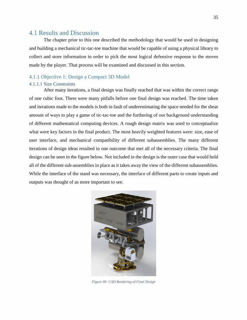
After many iterations, a final design was finally reached that was within the correct range
of one cubic foot. There were many pitfalls before one final design was reached. The time taken
and iterations made to the models is both in fault of underestimating the space needed for the shear
amount of ways to play a game of tic-tac-toe and the furthering of our background understanding
of different mathematical computing devices. A rough design matrix was used to conceptualize
what were key factors in the final product. The most heavily weighted features were: size, ease of
user interface, and mechanical compatibility of different subassemblies. The many different
iterations of design ideas resulted in one outcome that met all of the necessary criteria. The final
design can be seen in the figure below. Not included in the design is the outer case that would hold
all of the different sub-assemblies in place as it takes away the view of the different subassemblies.
While the interface of the stand was necessary, the interface of different parts to create inputs and
outputs was thought of as more important to see.
Figure 40: CAD Rendering of Final Design
36
During the design process, a serious concern was the loads parts would be able to handle.
Due to the size constraints that the project needed to fall within, some parts such as the tines, were
thousandths of an inch thick. While parts such as the tines were small, many did not transmit high
loads, rather they served as a counting system where their displacement was a more important
factor as the mass ratio of the tine to the pin it interfaced with was roughly 1:1.
4.1.1.2 Design with Intent to Manufacture
All parts that were drawn in SolidWorks had to be created with the intent of manufacturing.
Drawing parts in SolidWorks that could not be machined simply wasted time. Therefore, all CAD
parts were designed specific to the type of machining that would be used to create them i.e. CNC
versus manual machining. While certain gears were close to the correct size and had the right
number of teeth we needed, factors such as shaft diameter and overall diameter prevented the
purchase of these parts. Knowing that similar products also existed, McMaster Carr was used to
take the 3D models of parts that already existed for manufacturing and modifying them slightly to
fit the needs of our design.
4.1.1.3 Time Constraints
In order to complete as much of the project as possible, it was vital that machining of parts
began by at latest mid B-term. Time spent designing parts that fit their correct tolerances for the
model were made and most sub-assemblies were created and had proper interfacing. Given the
amount of iterations of the model made before the final design was created, a final design was not
confirmed until B- term. At this point, with the sheer volume of parts and interfaces needed to
create a working 3D model some of the more complicated mates were left out. It was determined
after discussion with the advising professor of the project that it was more critical to begin
machining as soon as possible once a practical design was created. While all of the parts were
created and put into one large assembly, not all of the parts interfaced correctly.
In order for the tines to be raised, interfacing with the tine block above them, the star gears
needed to pluck along the holes of the punch card. However, the punch card in SolidWorks never
had holes put in it so this feature of the final assembly did not allow for a simulation of playing
the game.
37
4.1.2 Objective 2: Machining and Assembly
4.1.2.1 Budget
The majority of the tic-tac-toe machine was built in house requiring the purchase of bulk
material and premade parts such as screws, bolts, etc. through McMaster Carr. Prices of parts
resulted in the project using all of the money budgeted by WPI. Money was taken from other MQP
groups that did not exhaust their funds and put towards the purchase of more materials for the
project. Without completing the project and purchasing all of the necessary materials to finish,
approximately $1,300 was spent on materials.
4.1.2.2 Scrapped Parts
During the machining and assembly of the computer, there were many parts scrapped. As
mentioned in previous sections, tolerances were expected to be very tight during machining. The
scrap rate of parts made for the computer was approximately 35-50%. In order to decrease this
number measures should have been taken for tighter tolerancing. Another reason for high scrap
rate was that some parts were made in bulk. For this reason, one of each part used in a sub assembly
was not made and tested as it was easier to repeat the same process over and over. Once all of the
parts for a sub assembly were made they were tested and if one part did not fit the right constraints
and had to be redesigned, it ended up being several of the same part wasted. A way to improve this
in the future is make less of the bulk parts at once and first test samples of each part to make sure
a portion of a system interfaces correctly.
Due to the time constraints driving the project, machining and assembly started while parts
were still being refined. In some cases, there were engineering changes during the assembly
process. While parts may have been designed in SolidWorks and worked in a software setting, it
was realized that some parts would not interface exactly as needed in the physical world. For this
reason, in some cases parts would be made and then it was discovered that changes needed to be
made to the model that would result in parts requiring modification. In most cases, engineering
changes happened before a part was made, but, on several occasions parts would be in the process
of being made when it was decided modifications to them were required.
4.1.3 Objective 3: Testing and Repeatability
While the total computer was not fully assembled, specific sub-assemblies that were
finished were able to be tested. These subassemblies and how they function are outlined below:
38
4.1.3.1 Playing Tiles
The playing tiles interface with a rack and pinion surface when the top is pushed down
vertically. The tile is held in place by the spring tab which rides in a slot on the top of the board
that is spring loaded. The first batch of spring tabs that were made were too loose in the slots that
were holding the system in place, causing for lack of interface between the rack and pinion and
instead the tab would just more away from the pinion. These original section of the spring tab had
two flat sides parallel one another with the other two sides being radial. The main problem of
making the tab interface with the hole it had to travel through was that the clearance on the flat
sides allowed for wiggle room. To fix this problem, a new set of spring tab pins were designed that
had a rounded region that interface with the board having a hole concentric to the spring tab,
limiting movement between parts.
4.1.3.2 Tines
Once the tines were made and the connecting rivets were hand peened, they were tested
with the hinge block that they interfaced with. Between each tine is two spacer blocks, both
towards the front half that interfaced with the star wheel. During testing the tines were manually
pushed to check if they interfaced correctly with the hinge block. The one flaw with the system is
that due to the spacer blocks being at the front of the tines, the back end of them tends to walk and
results in the tines next to one another pivoting and not remaining in parallel sets. In addition to
the back end of the tines moving, there is too large of a difference in the tolerancing of all the tines.
The tines were cut using a water jet and a different water jet needed to be used halfway through
the cutting process. This affected the tolerancing of each tine. With each tine having a slightly
different length, it is nearly impossible to get them to all interface with the star wheels properly.
4.1.3.3 Crankshaft
The crankshaft was one of our sub-assemblies that was built successfully and is fully
functioning. The crankshaft has four individual positions, all located at 90 degrees from one
another, that allow the system to index between all four layers of the game. The crankshaft allows
the computer to know what level the game is in to allow for the correct response. With a four
position system, only one level of the game is interfacing with the output at a time and this allows
the correct move to be read from the punch card as it rolls over the tines. Riding inside of the
blocks were a series of pins. These pins are able to move vertically within the riding blocks to
allow them to interface with the tines underneath and the arms above which indicate the output tile
39
the board responds with. These pins are contained within the riding blocks with 1/16th inch brass
pins that were hand peened into each one and then turned down on the manual lathe. The reason
for this is that each pin had a vertical stop placed and peened inside of it to restrict the motion
within the riding block.
4.1.3.4 Indexing Gear Box
Once assembled, the gear box did not rotate with ease. All of the gears meshed with one
another, but, causing the gears to rotate as an assembly did not work. To mediate this problem, the
gears were turned within their assembly for several hours by hand to allow for the gears to wear
into one another. All gears in this sub assembly were made of brass.
4.1.3.5 Gear Box Clutches
The assembly of the gear box was the last sub assembly put together before the project was
stopped. While the lower portion of the gear box, listed in the section above, was able to move as
intended, once the addition of the clutch mechanisms and more gears were added, the system
ceased to work. The amount of torque and shearing that occurred did not allow for the gears to
spin properly, resulting in some shearing between gears and their arbors and the system not
working. This sub assembly had a total of 170 parts within it. The main cause of the sub assembly
not being operational was tolerancing errors. Given the small scale parts were manufactured at,
machining and being off by a couple thousandths on a surplus amount of parts adds up. While
tolerancing errors on a couple parts would not be an issue, the stack up of slightly off parts was
too much for the system to be able to overcome.
4.2 Conclusions
4.2.1 Challenges
4.2.1.1 Output
In the end, we were not able to finish what we set out to accomplish. We ran out of time
and money to finish all of the parts required to make this a fully functioning, playable tic-tac-toe
board. Another major issue we ran into was machine tolerancing. Due to the extremely small nature
of the gears we made and the number of gears made, the gears did not all mesh perfectly and we
ran into issues getting the gear box to spin freely. At that size, gears being off by just one or two
thousandths of an inch create meshing problems that quickly add up when hand making that many
gears.
40
4.2.1.2 Punch Cards
In order for the data seen in the excel sheets in previous sections to be mechanically
readable it was required that it was transformed into a binary code. While this took approximately
two weeks to accomplish, the task of manufacturing the actual punch cards proved to be just as
difficult as designing them.
In order for the design to work, the holes imprinted in the punch cards needed to be
extremely accurate. It was determined that the most time efficient and precise way to go about this
was having the card water jet cut. The holes were all cut in the proper locations once cut with the
water jet, but, having to outsource the part to be cut outside of WPI campus did cause for a time
delay in getting the part back.
The punch card was one of the last parts done during the machining process, meaning that
the budget for the project was running dry and there was not enough money to buy enough material
for nine spools. For this reason, one spool was bought and the outputs for a game assuming that
the player pressed tile one first was made. While having all nine spools would be necessary for a
complete machine, having one and starting with a specific tile would still be able to show that the
computer was able to play through a game of tic-tac-toe. Due to time constraints, the cut spool was
not rolled and placed in the sub assembly to interface with the tine system. One factor that was
noted with the unrolled sheet of data was that there was some bends in the corners of the material.
It is assumed that if the spool was rolled and used, there would be some deformation and bending
that would not allow for the smooth rolling of data needed for the star gears to interface with the
holes.
4.2.1.3 Machining Availability
For the majority of the project, access to machines in Higgins shops, where the majority of
manual machining was done had a vast amount of availability. However, in Washburn shops,
where the majority of CNC machining was done, availability of different machines was limited.
Machining was limited due to the shear demand of projects that needed computer aided machining
done along with the presence of various lab groups, such as ME 1800, an introduction to machining
course that had the CNC machines booked during regular business hours on Tuesdays and
Thursdays, and an adult class that utilized machines in the mornings until 10:30 am multiple days
per week. As CNC machining was CAM intensive, the staff of Washburn shops were often utilized
41
to review and aid in the CAM aspect of machining, meaning that time must have been reserved
with the staff to have appointments to review programs before machining.
4.2.1.4 Time
Like most projects, a limiting factor was time. While approximately 500 parts were able to
be machined in house, the sheer magnitude of parts necessary to create a working model ultimately
was too great for a completed machine. Factors to consider in loss of time include the time making
parts that ultimately ended up being scrapped and available machine time. It was decided that it
was imperative to begin parts during the design phase of the project that were likely to not change
even if there were engineering changes, such as the playing tiles that the user interfaced with;
regardless of if the mechanisms within the computer changed, the user would still press a board
tile that was engraved with an “X” and “O.”
42
References
[1] “'Babbage's Analytical Engine' by Sydney Padua,” Redbubble. [Online]. Available:
https://www.redbubble.com/people/sydneypadua/works/15059232-babbages-analytical-
engine. [Accessed: 25-Apr-2018].
[2] “The Engines,” Computer History Museum. [Online]. Available:
http://www.computerhistory.org/babbage/engines/. [Accessed: 25-Apr-2018].
[3] History of Computers and Computing, Babbage, Analytical Engine. [Online]. Available:
http://history-computer.com/Babbage/AnalyticalEngine.html. [Accessed: 25-Apr-2018].
[4] The History of Computing. [Online]. Available: http://mason.gmu.edu/~montecin/computer-
hist-web.htm. [Accessed: 25-Apr-2018].
[5] “How many Tic-Tac-Toe (noughts and crosses) games are possible?,” How many Tic-Tac-Toe
(noughts and crosses) games?[Online]. Available: http://www.se16.info/hgb/tictactoe.htm.
[Accessed: 25-Apr-2018].
[6] M. N. Geselowitz, “The Jacquard Loom: A Driver of the Industrial Revolution,” The Jacquard
Loom: A Driver of the Industrial Revolution - IEEE - The Institute. [Online]. Available:
http://theinstitute.ieee.org/tech-history/technology-history/the-jacquard-loom-a-driver-of-the-
industrial-revolution. [Accessed: 25-Apr-2018].
[7] “Tic-tac-toe,” Wikipedia, 21-Apr-2018. [Online]. Available:
https://en.wikipedia.org/wiki/Tic-tac-toe. [Accessed: 25-Apr-2018].
[8] “The Two Towers Tradition,” Gordon Library: The Two Towers Tradition - WPI. [Online].
Available: https://web.wpi.edu/academics/library/collections/two-towers.html. [Accessed:
25-Apr-2018].
43
Appendices
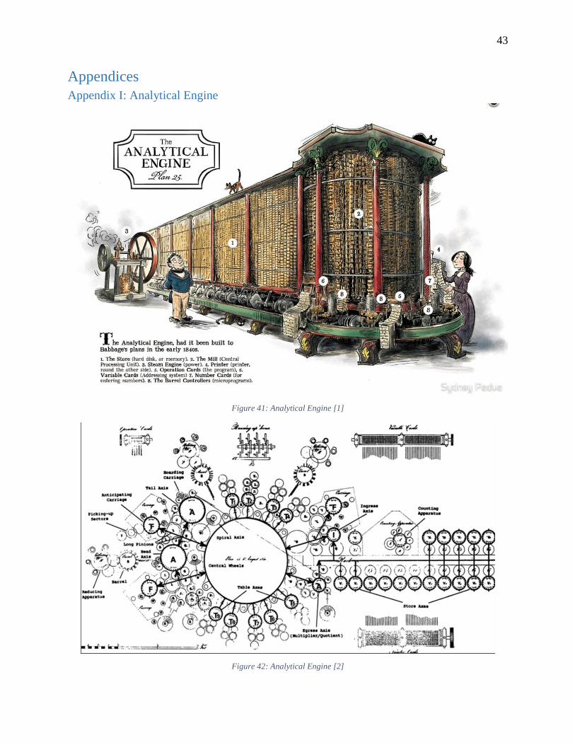
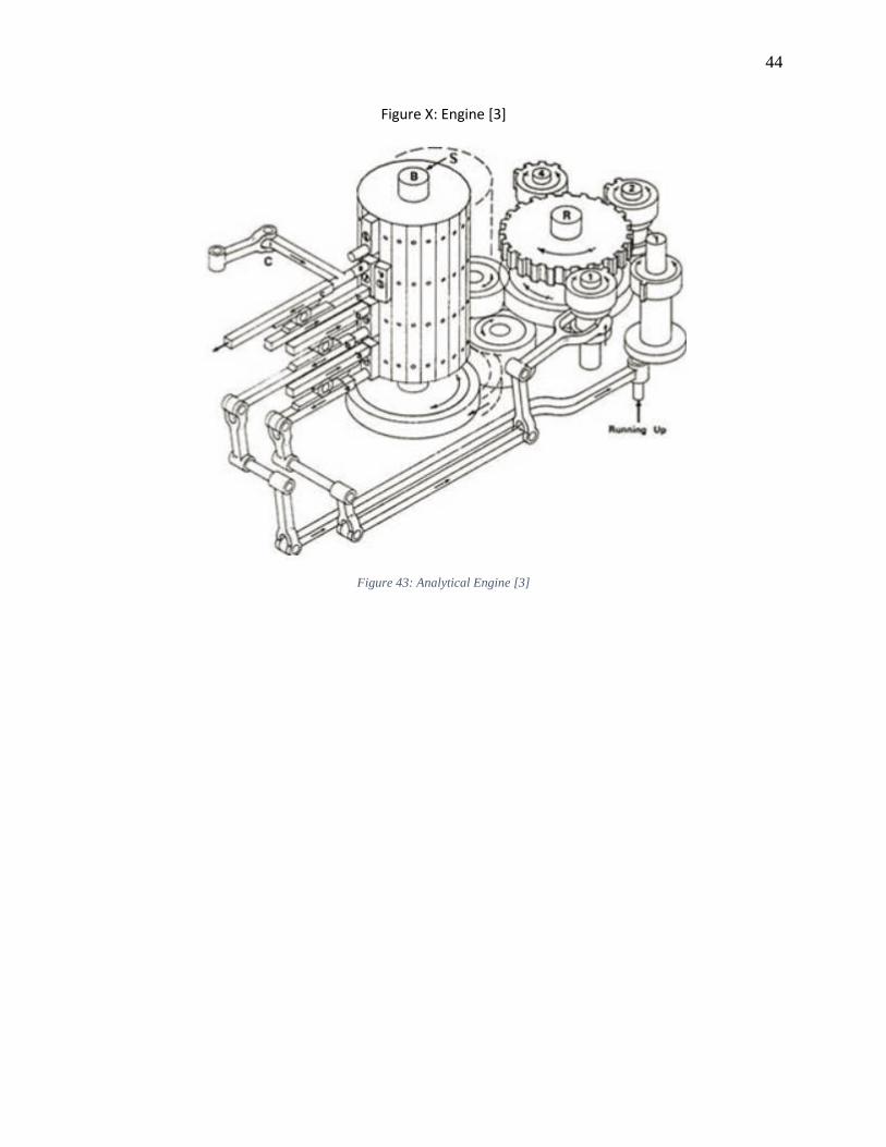
Appendix I: Analytical Engine
Figure 41: Analytical Engine [1]
Figure 42: Analytical Engine [2]
44
Figure X: Engine [3]
Figure 43: Analytical Engine [3]