Mechanical stratigraphy in the western equatorial …chriso/pubs/okubo.schultz.2004.pdf ·...
12
For permission to copy, contact [email protected] q 2004 Geological Society of America 594 GSA Bulletin; May/June 2004; v. 116; no. 5/6; p. 594–605; doi: 10.1130/B25361.1; 8 figures. Mechanical stratigraphy in the western equatorial region of Mars based on thrust fault–related fold topography and implications for near-surface volatile reservoirs Chris H. Okubo ² Richard A. Schultz Geomechanics–Rock Fracture Group, Department of Geological Sciences, Mackay School of Earth Sciences and Engineering, University of Nevada, Reno, Nevada 89557-0138, USA ABSTRACT Variations in lithology and pore-volatile pressure influence the distribution of layer and interface strength (mechanical stratig- raphy) within the crust. In this paper, we show how mechanical stratigraphy can be inferred from the topography of thrust fault–related folds. A thrust fault propa- gating upward through mechanically well- stratified crust induces the nucleation of secondary backthrust faults. Because such backthrusts are not predicted (and do not occur) in mechanically homogeneous crust, the presence of backthrusts can be used to map variations in the mechanical strength of the crust (e.g., bedding planes, volatile- saturated reservoirs). Dip directions of faults indicate the presence of strength dis- continuities within thrust-related folds. We show that the slopes of fault-related fold limbs are reliable indicators of fault-dip direction. We then apply this slope- asymmetry approach to thrust-related folds on Mars. We find that thrust-related folds that have secondary backthrusts are spa- tially correlated with a general lithologic se- quence of lava flows overlying older impact ejecta and young lobate ejecta craters on the lava-flow surface—evidence of near- surface volatiles such as water ice. We dem- onstrate that secondary backthrusts within fault-related folds in the western equatorial region of Mars formed because of volatile- enhanced mechanical stratification of lava- flow and ejecta lithologic sequences. Keywords: thrust fault, wrinkle ridge, to- ² E-mail: [email protected]. pography, mechanical stratigraphy, fluid flow, Mars tectonics. INTRODUCTION Field observations (King and Yielding, 1984; Stone, 1999), kinematic models (Suppe, 1985; Mercier et al., 1997), and numerical models (Stein and Ekstro ¨m, 1992; Cooke and Pollard, 1997; Fig. 1) show that folds around thrust faults are asymmetric in profile. The fold limb ahead of the upper thrust-fault tip (the forelimb) is steeper than the limb above the deeper sections of the thrust (the back- limb; Fig. 1). Accordingly, the asymmetry in fold-limb slope correlates with the dip direc- tion of the subjacent thrust fault. That is, the thrust fault is shallowest below the steep forelimb and dips toward and below the shallower-dipping backlimb. This slope- asymmetry relationship can be used to deter- mine thrust-fault geometries from topography. In this paper, we propose and validate a method for mapping subjacent fault-dip direc- tions and relative downdip fault lengths from the topography of thrust fault–related folds. We choose to evaluate fold topography be- cause such data are commonly available for terrestrial folds and are the principal (or only) source of structural information for planetary thrust-related folds (Golombek et al., 1991, 2001; Watters and Robinson, 1997; Kreslav- sky and Basilevsky, 1998; Bilotti and Suppe, 1999). Planetary landforms termed ‘‘wrinkle ridges’’ (Colton et al., 1972; Hodges, 1973; Howard and Muehlberger, 1973; Young et al., 1973) are commonly inferred to be thrust fault–related folds. As we shall show, fault- dip directions below wrinkle ridges can be used to interpret stratification of materials having varying mechanical strengths within the shallow Martian crust (e.g., Tanaka et al., 2003; Okubo and Schultz, 2002). The ultimate purpose of this analysis is to infer the presence of near-surface volatile (fluid or ice) reservoirs on the basis of wrinkle-ridge topography. FAULT DIP AND DEPTH FROM TOPOGRAPHY Planetary surfaces are cut by numerous fractures, bedding planes, and other mechani- cal strength discontinuities between blocks of intact rock. The effective strength of the shal- low crust is therefore dependent on the strength of intact shallow-crustal rocks com- bined with the strength of these generally weaker discontinuities. This collection of blocks of intact rock separated by mechanical discontinuities is commonly referred to as a fractured rock mass (e.g., Bieniawski, 1989; Bell, 1992; Priest, 1993) to distinguish the large-scale mechanical behavior of the shal- low crust from the small-scale behavior of in- tact rock. This study investigates the large- scale behavior of the shallow Martian crust at the scale where both intact rock and discon- tinuity strength are important. Therefore, we proceed with a brief introduction to rock-mass strength and deformability criteria. Rock-mass strength is commonly quantified by using the rock-mass rating (RMR) system, which is based on peak rock-mass strength de- termination at failed mines, tunnels, and nat- ural and engineered slopes (Bieniawski, 1978, 1989). As its name implies, this system uses a rating scale to quantify fracture density, the strength of the fracture walls and interstitial gouge, pore pressure within the fractures, and the strength of the intact rock. The rating val- ues for each parameter are summed to arrive at an RMR score (S RMR ) between zero and
Transcript of Mechanical stratigraphy in the western equatorial …chriso/pubs/okubo.schultz.2004.pdf ·...

For permission to copy, contact [email protected] 2004 Geological Society of America594
GSA Bulletin; May/June 2004; v. 116; no. 5/6; p. 594–605; doi: 10.1130/B25361.1; 8 figures.
Mechanical stratigraphy in the western equatorial region of Marsbased on thrust fault–related fold topography and implications
for near-surface volatile reservoirs
Chris H. Okubo†
Richard A. SchultzGeomechanics–Rock Fracture Group, Department of Geological Sciences, Mackay School of Earth Sciences and Engineering,University of Nevada, Reno, Nevada 89557-0138, USA
ABSTRACT
Variations in lithology and pore-volatilepressure influence the distribution of layerand interface strength (mechanical stratig-raphy) within the crust. In this paper, weshow how mechanical stratigraphy can beinferred from the topography of thrustfault–related folds. A thrust fault propa-gating upward through mechanically well-stratified crust induces the nucleation ofsecondary backthrust faults. Because suchbackthrusts are not predicted (and do notoccur) in mechanically homogeneous crust,the presence of backthrusts can be used tomap variations in the mechanical strengthof the crust (e.g., bedding planes, volatile-saturated reservoirs). Dip directions offaults indicate the presence of strength dis-continuities within thrust-related folds. Weshow that the slopes of fault-related foldlimbs are reliable indicators of fault-dipdirection. We then apply this slope-asymmetry approach to thrust-related foldson Mars. We find that thrust-related foldsthat have secondary backthrusts are spa-tially correlated with a general lithologic se-quence of lava flows overlying older impactejecta and young lobate ejecta craters onthe lava-flow surface—evidence of near-surface volatiles such as water ice. We dem-onstrate that secondary backthrusts withinfault-related folds in the western equatorialregion of Mars formed because of volatile-enhanced mechanical stratification of lava-flow and ejecta lithologic sequences.
Keywords: thrust fault, wrinkle ridge, to-
†E-mail: [email protected].
pography, mechanical stratigraphy, fluidflow, Mars tectonics.
INTRODUCTION
Field observations (King and Yielding,1984; Stone, 1999), kinematic models (Suppe,1985; Mercier et al., 1997), and numericalmodels (Stein and Ekstrom, 1992; Cooke andPollard, 1997; Fig. 1) show that folds aroundthrust faults are asymmetric in profile. Thefold limb ahead of the upper thrust-fault tip(the forelimb) is steeper than the limb abovethe deeper sections of the thrust (the back-limb; Fig. 1). Accordingly, the asymmetry infold-limb slope correlates with the dip direc-tion of the subjacent thrust fault. That is, thethrust fault is shallowest below the steepforelimb and dips toward and below theshallower-dipping backlimb. This slope-asymmetry relationship can be used to deter-mine thrust-fault geometries from topography.
In this paper, we propose and validate amethod for mapping subjacent fault-dip direc-tions and relative downdip fault lengths fromthe topography of thrust fault–related folds.We choose to evaluate fold topography be-cause such data are commonly available forterrestrial folds and are the principal (or only)source of structural information for planetarythrust-related folds (Golombek et al., 1991,2001; Watters and Robinson, 1997; Kreslav-sky and Basilevsky, 1998; Bilotti and Suppe,1999). Planetary landforms termed ‘‘wrinkleridges’’ (Colton et al., 1972; Hodges, 1973;Howard and Muehlberger, 1973; Young et al.,1973) are commonly inferred to be thrustfault–related folds. As we shall show, fault-dip directions below wrinkle ridges can beused to interpret stratification of materialshaving varying mechanical strengths within
the shallow Martian crust (e.g., Tanaka et al.,2003; Okubo and Schultz, 2002). The ultimatepurpose of this analysis is to infer the presenceof near-surface volatile (fluid or ice) reservoirson the basis of wrinkle-ridge topography.
FAULT DIP AND DEPTH FROMTOPOGRAPHY
Planetary surfaces are cut by numerousfractures, bedding planes, and other mechani-cal strength discontinuities between blocks ofintact rock. The effective strength of the shal-low crust is therefore dependent on thestrength of intact shallow-crustal rocks com-bined with the strength of these generallyweaker discontinuities. This collection ofblocks of intact rock separated by mechanicaldiscontinuities is commonly referred to as afractured rock mass (e.g., Bieniawski, 1989;Bell, 1992; Priest, 1993) to distinguish thelarge-scale mechanical behavior of the shal-low crust from the small-scale behavior of in-tact rock. This study investigates the large-scale behavior of the shallow Martian crust atthe scale where both intact rock and discon-tinuity strength are important. Therefore, weproceed with a brief introduction to rock-massstrength and deformability criteria.
Rock-mass strength is commonly quantifiedby using the rock-mass rating (RMR) system,which is based on peak rock-mass strength de-termination at failed mines, tunnels, and nat-ural and engineered slopes (Bieniawski, 1978,1989). As its name implies, this system usesa rating scale to quantify fracture density, thestrength of the fracture walls and interstitialgouge, pore pressure within the fractures, andthe strength of the intact rock. The rating val-ues for each parameter are summed to arriveat an RMR score (SRMR) between zero and

Geological Society of America Bulletin, May/June 2004 595
MECHANICAL STRATIGRAPHY BASED ON THRUST FAULT–RELATED FOLD TOPOGRAPHY
Figure 1. General relationships betweenthrust-related fold morphology and subja-cent thrust-fault geometry. Fold wave-length—the sum of the forelimb and back-limb lengths—is subequal to the length ofthe subjacent thrust fault as projected tothe surface. This thrust is shallowest belowthe steeper-dipping forelimb and dips to-ward and below the shallower-dippingbacklimb. By using these relationships, thedip direction and relative fault length of (A)a single (primary) thrust, as well as (B) anysecondary forethrusts or backthrusts, canbe inferred from fold topography.
Figure 2. Rock-mass strength, here identi-fied with rock-mass deformation modulus,E*, decreases with increasing pore pressurefor any given initially dry value of SRMR.The relative magnitude of strength reduc-tion is greatest for rock masses with lowvalues dry values of SRMR.
100; 100 is the strongest, reflecting a low frac-ture density of ,2 fractures per meter, un-weathered fracture walls, no interstitial gouge,and no pore pressure. RMR scores are thenrelated to rock-mass strength parametersthrough empirical relationships (Schultz,1996; Hoek and Brown, 1997).
The deformation modulus of a rock mass,E*, analogous to Young’s modulus for intactrock (Bieniawski, 1978; Schultz, 1996), is re-lated to SRMR through
E* 5 2S 2 100RMR (1)
for values of SRMR . 50 and
(S 210)/40RMRE* 5 10 (2)
for SRMR , 50. Increasing pore pressure, aswell as increasing fracture density or intersti-tial gouge content, decreases the SRMR of arock mass (Bieniawski, 1989) and thereby de-creases the magnitudes of E*. Values of rock-mass Poisson’s ratio, n*, also decrease withincreasing pore pressure (Dvorkin et al., 1999;Wu and Wang, 2001). The range of n* is typ-ically between 0.2 and 0.35, whereas E* gen-erally ranges range from 1 GPa to 50 GPa(e.g., Bieniawski, 1978; Hoek and Brown,1997).
The decrease in E* with increasing porepressure is demonstrated in Figure 2. For aninitially dry rock mass with SRMR of 30, a 20%increase in the ratio of pore pressure to themaximum principal compressive stress resultsin a 90% decrease in E*; the rock mass losesalmost all of its elastic stiffness. Conversely,an initially dry rock mass with an SRMR of 60loses only 40% of its initial elastic stiffnessfor the same increase in the pore pressure tocompressive stress ratio. Analogous decreasesin rock-mass strength parameters such as fric-tion and compressive strength are also pre-dicted. Therefore, increasing pore pressure notonly decreases the magnitude of rock-massshear modulus, but also increases the relativestrength contrast between adjacent rockmasses that have only slightly differentstrengths when dry.
Next, we summarize a series of numericalmodels that demonstrate the sensitivity offold-limb slopes to reasonable variations inrock-mass deformability, as well as to varia-tions in the dip and depth of the subjacentthrust fault. We use the two-dimensionalboundary-element-model FAULT (Schultzand Aydin, 1990; Schultz, 1992; Bruhn andSchultz, 1996; Appendix 1), which uses stan-dard displacement discontinuity equations(Crouch, 1976; Crouch and Starfield, 1983) tocalculate the material displacement fieldaround a slipped fault within a fractured rockmass.
The distributions of slip along model faultsand weak horizons are calculated in FAULTand are a function of the resolved stress acting
along the fault segments. The tendency forslip is evaluated from the resolved stressesand the frictional and cohesive strength ofeach segment. The magnitude and distributionof slip are then evaluated on the basis of thedeformation modulus of the crust surroundingeach slipping segment and the magnitudes ofthe resolved driving stress. In this way, themagnitude and distribution of slip (and crustaldisplacements) do not directly constitute a freeparameter, but are calculated as elastic dis-placements around a displacing fracture. Ac-cordingly, the magnitude and distribution ofslip and crustal displacements can vary withchanges in the strength and deformability ofthe crust, as well as with changes in faultlength and dip and far-field driving stress.
The effects of variations in model parame-ters on the predicted distribution and magni-tude of fault slip and resulting surface dis-placements (i.e., topography) are modeled bysystematically varying either (1) fault dip,depth, or downdip length or (2) rock-massstrength values of friction angle, f*, Poisson’sratio, n*, or deformation modulus, E*, whileholding constant all other variables of faultgeometry, material strength, and driving stress(e.g., Schultz and Lin, 2001). The specific ef-fects of changes in crustal strength, fault ge-ometry, and far-field stress on fold topographyare detailed in Figure 3. With the eliminationof fault-slip magnitude and distribution as afree parameter, the relationships in Figure 3show that variability in parameters that do af-fect fault slip (and thereby fold topography)do not drastically affect the principal slopeasymmetry. The thrust fault is consistentlyshallowest below the steep forelimb and dipstoward and below the shallower-dipping back-limb in all model variations. Additionally, foldwidth is subequal to the surface-projectedthrust-fault width. In line with field observa-tions and theoretical considerations of brittle-fault strain (Cowie and Scholz, 1992a, 1992b),the FAULT-predicted maximum fault dis-placement scales with fault length. Therefore,longer faults have larger maximum fault dis-placements. A corollary to this result is thatlonger-wavelength folds have greater maxi-mum thrust-fault offsets.
Therefore, although numerical inversions oftopography can yield nonunique solutions offault geometry, the general relationships be-tween fold morphology and fault geometrythat are the bases of the slope-asymmetrytechnique remain viable under reasonable var-iations of the free parameters that achieve thepredicted fault-slip distribution and fold to-pography. Thus, we conclude that (1) fault-dipdirection can be reasonably determined from

596 Geological Society of America Bulletin, May/June 2004
OKUBO and SCHULTZ
Figure 3. Sensitivity of a fold’s slope asymmetry under varying fault and material parameters. Slope-asymmetry relationships, as shownin Figure 1, remain valid for a reasonable range of thrust-fault-dip angles and common material properties.
topography when slope asymmetry can bemeasured beyond uncertainty in topographicdata, and (2) relative downdip fault lengthscan be approximated by fold wavelength.
APPROACH
Mechanical stratigraphy describes the spa-tial distribution of rock-mass strength and de-formability (Corbett et al., 1987; Peacock andZhang, 1994; Gross, 1995; Gross et al., 1997).A mechanically well-stratified crust is com-posed of alternating strong and weak layers orlayer interfaces, such as in an interbedded se-quence of mechanically strong limestone andweak shale. A mechanically homogeneousstratigraphy has a uniform strength distribu-tion, such as in a thick sequence of sandstone.In addition to changes in lithology, mechani-cal stratigraphy can also be caused by vari-ability in pore pressure. Elevated pore pres-sure of volatile species, such as within aconfined aquifer, reduces the effective strengthof the reservoir rock mass (Hoek, 1983; Byer-
lee, 1990; Dvorkin et al., 1999) and can resultin volatile-induced mechanical stratificationwithin a single lithologic unit.
Thrust-fault geometry can be used to char-acterize mechanical stratification within athrust-related fold because crustal-strengthdistribution strongly influences the tendencyfor thrust-fault propagation and secondary-fault nucleation, as evaluated with Coulombfailure stress change (Roering et al., 1997;Okubo et al., 2001) and the more generalHoek-Brown failure criterion (Hoek, 1983) forfractured rock masses (Okubo and Schultz,2002; and this paper). Displacement along anupward-propagating thrust fault induces slipalong mechanically weak horizons within theoverlying crust (Cooke and Pollard, 1997).This process leads to localization of secondarybrittle strain (Nino et al., 1998) consistentwith, and enhances the tendency for nucle-ation of (Roering et al., 1997; Appendix 1),secondary backthrust faults. Furthermore, nu-merical models demonstrate that in the ab-sence of mechanically weak horizons, the
thrust fault can propagate unimpeded to thesurface and, what is more significant, the nu-cleation of secondary backthrusts is not pre-dicted (Appendix 1). Therefore, we proposethat a backthrust fault within the fold sur-rounding a larger primary thrust fault is evi-dence that the primary thrust intersected a me-chanically weak layer or interface duringupdip propagation. Additionally, we suggestthat the depth of this weak horizon coincideswith the depth of the intersection between thebackthrust and the primary thrust fault.
A secondary backthrust fault can be iden-tified by an antithetic dip direction vs. the dipof the larger primary thrust (Fig. 1), as wellas a shorter downdip fault length relative tothe primary thrust. The topography of a thrust-related fold containing a secondary backthrusttherefore consists of two antiforms of differentwavelengths and senses of slope asymmetry.The fold surrounding the primary thrust ismanifested at the surface as the longer-wavelength antiform. Superimposed on thisprimary antiform is the shorter-wavelength an-

Geological Society of America Bulletin, May/June 2004 597
MECHANICAL STRATIGRAPHY BASED ON THRUST FAULT–RELATED FOLD TOPOGRAPHY
tiform of the fold surrounding the shorter sec-ondary backthrust. The secondary antiformwould have an opposite sense of slope asym-metry to that of the primary antiform, reflect-ing its antithetic dip to the primary thrust. Inthis way, secondary backthrust faults can bededuced from thrust-related fold topographyand thereby lead to interpretations of subja-cent mechanical stratigraphy.
Mars Topographic Data
Martian thrust-related folds are especiallysuited to topographic analyses owing to min-imal erosion of the anticlinal fold surface,minimal sediment cover, and surface expo-sures that are unobstructed by vegetation. Ad-ditionally, thrust-related folds are distributedacross the entire planet, within terranes of di-verse origin and geologic history. The litho-logic and volatile-induced variations that areinterpretable from mechanical stratigraphyprovide an important link between observablewrinkle-ridge topography and the subsurfacegeology of the Martian crust.
Slope-asymmetry analysis relies upon ac-curate, high-spatial-resolution topography ofthrust-related anticlines. Such data are cur-rently available on a global scale for Mars viathe Mars Orbiter Laser Altimeter (MOLA) in-strument (Zuber et al., 1992) aboard the MarsGlobal Surveyor (MGS) spacecraft (Albee etal., 1998). MOLA data are available as irreg-ularly spaced spot elevations and as continu-ous surface digital elevation models (DEMs).We have found that the currently availableDEMs are too coarse for slope-asymmetryanalysis of thrust-related folds, and thereforewe made grids of the irregularly spaced spotelevations to create DEMs with resolutions of200 pixels per degree, or ;297 m/pixel at theequator (Appendix 2). These customizedDEMs are used as the basis for the followingapplications.
Slope-Asymmetry Technique
Topographic inversion modeling is com-monly used to predict fault-dip angle, fault-dip direction, fault length, and displacementdistribution from observations of coseismicdisplacements (Lin and Stein, 1989; Stein andEkstrom, 1992) or topography (Taboada et al.,1993; Schultz and Watters, 2001). In this in-version method, material (i.e., crustal) dis-placements are calculated around a modelfault of prescribed dip and length. Predictedmaterial displacements at the surface are com-pared with observed topography, and the mod-el fault geometry is iteratively varied until
model surface displacements are consistentwith topography. In Earth-based studies of co-seismic surface displacements, fault geome-tries predicted by this method are consistentwith the locations of the related earthquakehypocenters (Lin and Stein, 1989; Ekstrom etal., 1992) and focal mechanisms (Stein andEkstrom, 1992).
The method of slope-asymmetry analysisproposed here is an alternative to the topo-graphic inversion method for evaluating thepresence of secondary backthrusts in thrust-related folds. The principal advantage of theslope-asymmetry technique is its efficiency inevaluating large data sets. For each topograph-ic inversion profile, tens to hundreds of iter-ations of fault geometry and driving stressmust be tested, and each iteration may require10–20 min or more of preparation and pro-cessing time. In a large mapping area wherehundreds of profiles may be required, topo-graphic inversion is time-consuming and re-turns predictions of downdip fault length, far-field stress magnitudes, slip magnitude anddistribution, as well as dip angle and dip di-rection. In contrast, the slope-asymmetry tech-nique requires 1–2 min per profile in order todetermine the only two parameters that are re-quired for this analysis: fault-dip directionsand relative downdip fault lengths.
Slope-asymmetry analysis is demonstratedon cross-strike topographic profiles extractedalong a single thrust-related fold in southeastSolis Planum, in the western equatorial regionof Mars (Fig. 4). A total of 10 profiles wereconstructed along this wrinkle ridge, adjacentto the four representative profiles shown inFigure 4. The six profiles not shown havecomparable dip directions and fault lengths asthe four shown profiles. These profiles areconstructed away from major lava flows andlarge impact craters, as apparent in Viking Or-biter and Mars Orbiter Camera imagery; suchlava flows and impact craters would obscurethe wrinkle-ridge topography. Fold wave-length (i.e., the sum of the forelimb and back-limb widths) is used as a relative scale for thesurface-projected width of these faults. There-fore the longest thrust within the fold is inter-preted as the primary fault, implying that thisfault is the most deeply rooted. Shorter faultsare interpreted as secondary thrusts and arecharacterized as either backthrusts or fore-thrusts depending on the interpreted dip anglerelative to that of the primary thrust.
Our cross-strike profiles reveal two anti-forms, each characterized by distinct limbs(Fig. 4). A narrow 7–20-km-wide antiform isobserved on, or adjacent to, a broader 20–35-km-wide antiform, consistent with previous
observations of wrinkle ridges (Watters, 1988;Golombek et al., 1991; Watters and Robinson,1997; Schultz, 2000). We identify this broadantiform as the surface expression of a folddeveloped above the longer primary fault. Thenarrow antiform is interpreted to consist oftwo distinct folds, one surrounding the near-surface upper tip of the primary thrust and onesurrounding a secondary fault.
Slopes of the broader, primary fault-relatedfold, as well as the smaller fold surroundingits upper tip, are steepest on the east-facinglimbs and shallowest on the west. Therefore,according to slope-asymmetry relationships,the primary fault is interpreted to be west dip-ping. In contrast, the slopes of the narrowersecondary fault-related fold are steepest on thewest-facing limb and shallowest on the east,indicating by slope asymmetry that the sub-jacent fault is east dipping. This east-dippingsecondary fault is antithetic to the west-dipping primary thrust and is therefore inter-preted as a secondary backthrust fault, imply-ing the presence of a weak horizon at depth.
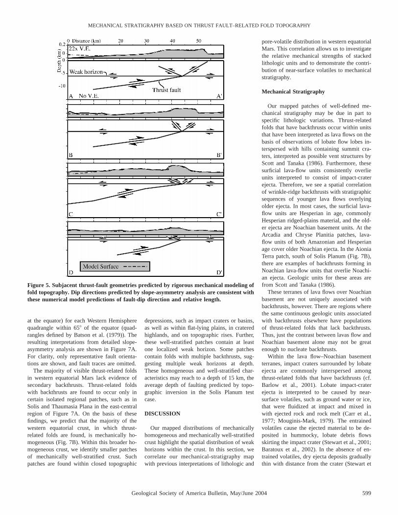
Four cross-strike profiles are next evaluatedwith rigorous topographic inversion modelingusing FAULT (Fig. 5). We model the cumu-lative ground-surface displacements due toslip and local stress change along both the pri-mary and secondary thrusts. Both thrusts slipsimultaneously; the local stress change due toslip along the primary thrust influences themagnitude and distribution of resolved stress-es acting along the backthrust and vice versa.Stress interactions between both faults aresolved iteratively until numerical convergenceis achieved.
We find that the FAULT-predicted best-fitthrust geometries for each profile are consis-tent with the dip directions and relative down-dip fault lengths interpreted by slope asym-metry (compare Figs. 4 and 5). Theslope-asymmetry technique is also comparedto topographic inversion of thrust-related foldsin Isidis Planitia and southern Utopia Planitiain eastern equatorial Mars, and we find similarconsistent results (Okubo and Schultz, 2003).Therefore, we propose that results of theslope-asymmetry technique are consistentwith the results of, and are a viable qualitativealternative to, the more rigorous topographicinversion analysis.
As Figure 5 shows, local stress interactionbetween the backthrust and primary thrustdoes not invalidate the slope-asymmetry re-lationship. The magnitude of resolved localstress change due to slip along a nearby faultis insufficient to result in a significantly dif-ferent material-displacement distribution. Thefold slope is still steepest above the upper

598 Geological Society of America Bulletin, May/June 2004
OKUBO and SCHULTZ
Figure 4. Application of slope-asymmetry analysis to four cross-strike topographic profiles taken along a typical thrust-related fold insoutheast Solis Planum, Mars. MOLA-based topography is represented by a solid line with gray undershading, and the general dipdirections and lengths of the subjacent thrust fault interpreted from slope asymmetry are shown by dashed lines.
thrust tip and shallower dipping above thedeeper parts of the thrust. If the backthrust andprimary thrust do not slip simultaneously andoffsets along them are separated by a consid-erable period of time, then interseismic vis-coelastic relaxation would dissipate the slip-induced local stress magnitudes to someextent (e.g., Freed and Lin, 1998) and therebydiminish the effect of local stress interactionbetween the two faults.
APPLICATION
Solis Planum
We next apply slope-asymmetry analysis toa larger area of Solis Planum that includes thedemonstration-case wrinkle ridge (Fig. 6A).
Our method of mapping continuous thrust-fault traces from interpretations of fault dip atindividual profiles is outlined in Appendix 3.The central and lower regions of the mappedarea contain wrinkle ridges that show no to-pographic evidence of secondary backthrusts,as determined by slope asymmetry. Thesenonbackthrust folds have either secondaryforethrusts (smaller thrusts dipping subparallelwith the primary thrust) or have only a pri-mary thrust with no apparent secondary faults.Conversely, the wrinkle ridges along the east-ern and western extents of the mapped areashow topographic evidence of secondarybackthrusts.
Our mapped fault traces are generally con-sistent with previous mapping efforts (Chicar-ro et al., 1985; Scott and Tanaka, 1986; Wat-
ters and Maxwell, 1986). What is moresignificant, however, is that Figure 6B showsfor the first time the dip directions of thesethrust faults and specifically delineates occur-rences of secondary backthrust faults. Fromthe mapped distribution of backthrusts, we cannow predict the presence of a localized, me-chanically weak horizon at depth within thecentral region of Solis Planum (Fig. 6B). Thesignificance of this weak horizon is discussedin a later section.
West Equatorial Mars
Next, we apply the slope-asymmetry tech-nique to the entire western equatorial regionof Mars. Here, we use MOLA-based DEMshaving 200 pixels per degree (;297 m/pixel
Geological Society of America Bulletin, May/June 2004 599
MECHANICAL STRATIGRAPHY BASED ON THRUST FAULT–RELATED FOLD TOPOGRAPHY
Figure 5. Subjacent thrust-fault geometries predicted by rigorous mechanical modeling offold topography. Dip directions predicted by slope-asymmetry analysis are consistent withthese numerical model predictions of fault-dip direction and relative length.
at the equator) for each Western Hemispherequadrangle within 658 of the equator (quad-rangles defined by Batson et al. (1979)). Theresulting interpretations from detailed slope-asymmetry analysis are shown in Figure 7A.For clarity, only representative fault orienta-tions are shown, and fault traces are omitted.
The majority of visible thrust-related foldsin western equatorial Mars lack evidence ofsecondary backthrusts. Thrust-related foldswith backthrusts are found to occur only incertain isolated regional patches, such as inSolis and Thaumasia Plana in the east-centralregion of Figure 7A. On the basis of thesefindings, we predict that the majority of thewestern equatorial crust, in which thrust-related folds are found, is mechanically ho-mogeneous (Fig. 7B). Within this broader ho-mogeneous crust, we identify smaller patchesof mechanically well-stratified crust. Suchpatches are found within closed topographic
depressions, such as impact craters or basins,as well as within flat-lying plains, in crateredhighlands, and on topographic rises. Further,these well-stratified patches contain at leastone localized weak horizon. Some patchescontain folds with multiple backthrusts, sug-gesting multiple weak horizons at depth.These homogeneous and well-stratified char-acteristics may reach to a depth of 15 km, theaverage depth of faulting predicted by topo-graphic inversion in the Solis Planum testcase.
DISCUSSION
Our mapped distributions of mechanicallyhomogeneous and mechanically well-stratifiedcrust highlight the spatial distribution of weakhorizons within the crust. In this section, wecorrelate our mechanical-stratigraphy mapwith previous interpretations of lithologic and
pore-volatile distribution in western equatorialMars. This correlation allows us to investigatethe relative mechanical strengths of stackedlithologic units and to demonstrate the contri-bution of near-surface volatiles to mechanicalstratigraphy.
Mechanical Stratigraphy
Our mapped patches of well-defined me-chanical stratigraphy may be due in part tospecific lithologic variations. Thrust-relatedfolds that have backthrusts occur within unitsthat have been interpreted as lava flows on thebasis of observations of lobate flow lobes in-terspersed with hills containing summit cra-ters, interpreted as possible vent structures byScott and Tanaka (1986). Furthermore, thesesurficial lava-flow units consistently overlieunits interpreted to consist of impact-craterejecta. Therefore, we see a spatial correlationof wrinkle-ridge backthrusts with stratigraphicsequences of younger lava flows overlyingolder ejecta. In most cases, the surficial lava-flow units are Hesperian in age, commonlyHesperian ridged-plains material, and the old-er ejecta are Noachian basement units. At theArcadia and Chryse Planitia patches, lava-flow units of both Amazonian and Hesperianage cover older Noachian ejecta. In the AioniaTerra patch, south of Solis Planum (Fig. 7B),there are examples of backthrusts forming inNoachian lava-flow units that overlie Noachi-an ejecta. Geologic units for these areas arefrom Scott and Tanaka (1986).
These terranes of lava flows over Noachianbasement are not uniquely associated withbackthrusts, however. There are regions wherethe same continuous geologic units associatedwith backthrusts elsewhere have populationsof thrust-related folds that lack backthrusts.Thus, just the contrast between lavas flow andNoachian basement alone may not be greatenough to nucleate backthrusts.
Within the lava flow–Noachian basementterranes, impact craters surrounded by lobateejecta are commonly interspersed amongthrust-related folds that have backthrusts (cf.Barlow et al., 2001). Lobate impact-craterejecta is interpreted to be caused by near-surface volatiles, such as ground water or ice,that were fluidized at impact and mixed inwith ejected rock and rock melt (Carr et al.,1977; Mouginis-Mark, 1979). The entrainedvolatiles cause the ejected material to be de-posited in hummocky, lobate debris flowsskirting the impact crater (Stewart et al., 2001;Baratoux et al., 2002). In the absence of en-trained volatiles, dry ejecta deposits graduallythin with distance from the crater (Stewart et

600 Geological Society of America Bulletin, May/June 2004
OKUBO and SCHULTZ
Figure 6. Structural map of southern Solis Planum based on slope-asymmetry analysis ofwrinkle-ridge topography. (A) Predictions of fault-dip direction based on analysis of in-dividual cross-strike profiles are linked along strike of the wrinkle ridges to create (B) amap of dip directions of the subjacent thrust fault for the region. Mechanically well-stratified crust is interpreted in areas where wrinkle ridges contain evidence of secondarybackthrust faults. See Appendix 3 for details on our mapping approach.
al., 2001). Therefore, lobate ejecta craters areinterpreted as evidence of near-surface volatilereservoirs. The spatial correlation of lobateejecta craters with wrinkle-ridge backthrustswithin the key lava flow–Noachian basement(cf. Plate 1 of Barlow et al. [2001] with Fig.7) terranes suggests that near-surface volatilereservoirs enhance the tendency for the nucle-ation of wrinkle-ridge backthrusts.
Recent mapping along the equatorial re-gions of Mars by Barlow et al. (2001) showsa statistically large number of small lobatecraters with diameters of ,5 km in Solis andThaumasia Plana. Crater excavation depth hasbeen shown to correlate with crater diameter(Croft, 1980; Garvin et al., 1999), so thatsmaller craters excavate to shallower depths.Assuming that most of the ejecta are derived
from the top 1/3 of the crater (Melosh, 1989),Barlow et al. predicted volatile reservoirswithin 175 m to 240 m of the surface in Solisand Thaumasia Plana. The anomalously largeabundance of small lobate craters (and corre-spondingly shallow excavation depths) sug-gests that the volatile reservoirs in these planaare at significantly shallower depths than inother equatorial regions that contain lobatecraters. Significantly, the mapping results pre-sented here show localized occurrences of sec-ondary backthrusts in Solis and ThaumasiaPlana, where Barlow et al. (2001) predictedshallow volatile reservoirs. The correlation ofpossible near-surface volatile reservoirs andbackthrust formation suggests that volatile-induced strength loss may enhance mechani-cal stratification within western equatorialMars.
Pore pressure of volatile species—i.e., pore-volatile pressure—can enhance mechanicalstratigraphy by preferentially reducing thestrength of reservoir host rock (e.g., Fig. 2).Volatile pressure can be driven by a hydro-static head in the case of fluids or can becaused by the expansion of ice during freez-ing. Fractured rock masses are natural volatilereservoirs in which volatiles reside withinfracture voids and the intragranular pore spaceof the intact rock (Manzocchi et al., 1998; Ind-raratna and Ranjith, 2001).
The frictional strength of fracture walls iscommonly lower than the strength of the in-tact rock, and therefore the frictional strengthof the fractures largely controls the deforma-bility of the larger rock mass. If Coulombfrictional-sliding conditions are assumed, frac-ture strength is a function of the cohesion ofthe fracture walls, C, the friction angle of thewall rock or fill, f*, the magnitude of pore-volatile pressure within the fracture, P, and themagnitudes of the normal stress, sn, and shearstress, t, acting on the fracture:
t 5 C 1 (s 2 P)tan f*.n (3)
Pore-volatile pressure within the fracture actsto reduce the magnitude of the effective nor-mal stress acting on the fracture walls. Thisnormal-stress decrease reduces the frictionalresistance of the fracture and allows the frac-ture to slip at a lower magnitude of shearstress than if the fracture was completely dry(P 5 0). Thus, the presence of pore-volatilepressure reduces the frictional strength of frac-tures and thereby reduces the strength of thelarger rock mass (Bieniawski, 1989).
Interstitial ice can further reduce thestrength of a rock mass in a manner similar tothat of gouge. Clayey gouge commonly has

Geological Society of America Bulletin, May/June 2004 601
MECHANICAL STRATIGRAPHY BASED ON THRUST FAULT–RELATED FOLD TOPOGRAPHY
Figure 7. (A) Representative thrust-fault strike and dip directions for wrinkle ridges withinthe western equatorial region of Mars. (B) Mechanically well-stratified crust is interpretedbelow patches of wrinkle ridges that have secondary backthrust faults.
friction angles of less than 108 (Saffer et al.,2001; Morrow et al., 2000), which is signifi-cantly lower than general friction angles forintact rock (308–518; Kulhawy, 1975). Thepresence of frictionally weak gouge can re-duce the effective frictional strength of frac-ture surfaces between blocks of stronger intactrock, leading to lower values of SRMR and re-sulting in decreased rock-mass strength (Bien-iawski, 1989; Hoek and Brown, 1997;Schultz, 1996). In pure water ice, frictionalsliding tests yield internal friction angles of;118 under confining pressures of 10–200MPa (Durham et al., 1983; Beeman et al.,1988). These data suggest that interstitial ice,like gouge, can effectively reduce the strengthof fracture surfaces between intact rock blocksand result in decreased rock-mass strength.
The magnitude of volatile-induced strengthloss of a rock mass is dependent on the drystrength of the rock mass and is significantlygreater for rock masses with inherently lowunsaturated strength. Elevated pore-volatile(fluid or ice) pressure can enhance preexistingrock-mass strength contrasts by significantlydecreasing the relative strength of layers orlayer interfaces that are otherwise only slight-ly weaker than the surrounding rock when dry.In this way, increases in a pore-volatile com-ponent significantly affect the degree of me-chanical stratification within the lava flow–Noachian basement lithologic terranes inwestern equatorial Mars and thereby enhancethe tendency for backthrust nucleation.
Because the dry (no lobate ejecta) lavaflow–Noachian basement terranes have nobackthrusts, the contrast in unsaturated rock-mass strength of these layers and their inter-face is not sufficient to cause one (either alayer or the interface) to act as a relativelyweak horizon and nucleate backthrusts. Theapparent dependency of backthrust nucleationon elevated pore-volatile pressure suggeststhat individually, the lava-flow rock massesand the underlying Noachian sedimentary de-posits have only slightly different strengthswhen dry. Such a strength condition wouldprevent the nucleation of backthrusts in theabsence of pore-volatile pressure, but wouldallow for backthrust nucleation, abovevolatile-induced weak horizons, when saturat-ed. This deduction implies that the ejecta de-posits have a strength similar to that of theoverlying lava-flow rock mass. It is interestingto note that this statement provides a test ofthe interpretation that these underlying Noa-chian deposits consist of impact ejecta.
The frictional strength of granular depositsand poorly indurated sedimentary sequencesdepends on the clast-size distribution (sort-

602 Geological Society of America Bulletin, May/June 2004
OKUBO and SCHULTZ
ing), packing (porosity), and clast shape. Fric-tion is less than that of intact rock and rockmasses for rounded clasts, higher porosity,and uniform clast size. Deposits composed ofangular clasts can be as strong as induratedrock masses regardless of clast size and sort-ing (Mair et al., 2002). As a result, formationand transport mechanisms exert a significantcontrol on the strength and deformability ofthese materials. In our study area, the appar-ently approximate equality of the strength ofthe underlying deposits and that of the youn-ger lava-flow rock mass is thus consistent withthe underlying deposits’ being composed ofangular clasts. High clast angularity is char-acteristic of locally derived sediment that hasundergone minimal transport or reworking,such as the colluvium characteristic of terres-trial impact ejecta (Grant and Schultz, 1993;Urrutia-Fucugauchi et al., 1996; Lilljequist,2000). Therefore, the apparent frictionalstrength of the Noachian basement rocks isconsistent with the strength of impact ejectaand supports previous interpretations of thesebasement rocks.
Volatile-Rich Decollements
Martian wrinkle ridges have been interpret-ed as evidence of thin-skinned deformationabove volatile-rich decollements on the basisof deflections in observed wrinkle-ridge trendsaround the peripheries of partially and com-pletely buried impact craters (Allemand andThomas, 1992; Mangold et al., 1998). Thesestudies propose a primary thrust and second-ary backthrust geometry for the subjacentwrinkle-ridge faults. They further suggest thatthe primary thrust forms because of slip alongshallow, subhorizontal, ice-rich decollementswithin 3 km of the surface.
Alternatively, we suggest that ice- or fluid-rich layers have a secondary role in wrinkle-ridge formation. That is, shallow volatile-richlayers only act to promote secondary back-thrust nucleation by reducing rock-massstrength. In the absence of volatile-rich layers,the primary thrust and secondary forethrustscan still form, but only secondary backthrustnucleation is not predicted. Further, our to-pographic inversion results predict that, in-stead of being rooted in a shallow decolle-ment, the primary thrust of the test wrinkleridge of the Solis Planum must be deeply root-ed at .10 km depth in order to have surfacedisplacements consistent with observed topog-raphy. Thus, shallow volatile-rich layers en-hance the tendency for secondary backthrustnucleation, but are not required for wrinkle-ridge formation.
CONCLUSIONS
Comparisons with numerical models of dis-placements around slipped thrust faults dem-onstrate that the asymmetry in fold-limb slopeis a reliable indicator of subjacent fault-dip di-rection when applied to the topography ofthrust-related folds. In addition, the relativedowndip length of these faults can be approx-imated from the wavelength of the overlyingfold at the surface. Where secondary back-thrust faults are interpreted from slope asym-metry, the crust within the fold can be char-acterized as being mechanically well-stratifiedsuch that the crust contains a mechanicallyweak horizon at the intersection of the lowerbackthrust tip and the plane of the larger pri-mary fault. This horizon may be caused by amechanically weak lithologic layer or layer in-terface or by pressure-induced strength losswithin a volatile reservoir.
When applied to the topography of thrust-related folds on Mars, the physical principlesof slope asymmetry and backthrust nucleationat weak horizons suggest distributions of me-chanical stratigraphy. On the basis of spatialcorrelations of interpreted secondary back-thrusts in thrust-related folds, previous geo-logic mapping, and evidence of near-surfacevolatiles, we propose that the following state-ments hold true in western equatorial Mars:(1) Thrust-related folds that have backthrustsoccur in terranes that have a surficial lava-flowrock mass overlying sediments interpreted tobe Noachian basement rocks. (2) The lava-flow rock masses and the underlying Noachiansedimentary deposits have only slightly dif-ferent mechanical strengths when dry. (3) Theapparent strength of the underlying Noachiansediments is consistent with angular impact-derived ejecta colluvium, a finding that sup-ports previous interpretations of these units(e.g., Scott and Tanaka, 1986). (4) Variabilityin pore-volatile pressure may significantly af-fect the degree of mechanical stratificationwithin the key lava flow–Noachian basementlithologic terranes. (5) Shallow volatile-richlayers are not required for wrinkle-ridge for-mation, but only serve to enhance the tenden-cy for secondary backthrust nucleation. (6)The secondary backthrusts and causative pri-mary faults propagated in the presence ofnear-surface volatiles.
If backthrust nucleation is linked to near-surface volatile reservoirs (as we infer), thenthrust-related folds that have backthrusts maybe important locales for volatile seeps. Near-surface or surface-breaking faults are primelocations for seeps because these faults act tolocalize volatile flow, as either conduits (Sib-
son et al., 1975; Trave et al., 1997; Strayer etal., 2001) or as barriers (Antonellini and Ay-din, 1994; Parry, 1998). Furthermore, slipalong faults can generate substantial heat(Mase and Smith, 1987; Sleep, 1995), whichmay act to melt permafrost within adjacentwall rock and potentially lead to volatile re-lease at the surface. Our topographic inversiontests in Solis Planum predict that the subjacentthrusts in fact break the surface. This resultmeans that some thrust-related folds that havebackthrusts may have surface-breaking thruststhat crosscut shallow volatile reservoirs (suchas in Solis and Thaumasia Plana) and thatseeps may occur along the rupture lengthof these faults. Therefore, detailed re-mote sensing–based investigations of thesebackthrust-related fault systems may revealevidence of volatile release, in the form ofsprings or seeps.
APPENDIX 1. FAULT-BOUNDARY-ELEMENT MODEL
In FAULT, we model vertical variations in fric-tional strength as mechanical stratigraphy. Frictionalstrength variations are represented by verticalchanges in fault dip by assuming optimally orientedthrust faults (Jaeger and Cook, 1979) within an An-dersonian stress state (Anderson, 1951) and minimallocal stress rotation. Aside from friction angle, themodel rock-mass boundary elements have other-wise uniform properties such that E* 5 20 GPa andn* 5 0.25. This rock-mass value of E* correspondsto SRMR 5 64, consistent with an unweathered tomoderately weathered, average-quality rock mass(Hoek and Brown, 1997). Fault elements have E*5 20 GPa, n* 5 0.25, cohesion C 5 0.3 MPa,friction angle f* 5 208. Weak horizon elements(where present) have E* 5 3 GPa, n* 5 0.25, co-hesion C 5 0.3 MPa, friction angle f* 5 208. Themagnitude of the far-field driving stress is pre-scribed to correspond to a uniform principal stressratio of 4.5, under a half-space boundary condition,and the least compressive principal stress is equalto lithostatic load, if a crustal density of 2600 kg/m3 is assumed. Thus, the magnitudes of these prin-cipal stresses are depth dependent.
By using these model boundary conditions,Hoek-Brown stress states for model thrust-relatedfolds are calculated in cross-strike profile andmapped as factors of safety. Hoek-Brown predictsthe failure stresses required to nucleate faultingwithin a fractured rock mass (Hoek and Brown,1980, 1997) and is similar in form to the Coulombfailure criterion for intact rock (e.g., Schultz, 1996).The Hoek-Brown factor of safety (FHB) is the ratioof the frictional and cohesive strength of the rockmass to the maximum effective principal compres-sive stress. Accordingly, faulting is predicted wherethe factor of safety is ,1.
The distribution of FHB is first calculated for thecase of a mechanically stratified crust, where a weaksurface layer overlies a relatively stronger base-ment. In an Andersonian stress state for thrust fault-ing, where the maximum compressive stress acts inthe horizontal direction, the dip of optimally ori-ented thrust faults is equal to the rock-mass frictionangle (e.g., Jaeger and Cook, 1979). Accordingly,

Geological Society of America Bulletin, May/June 2004 603
MECHANICAL STRATIGRAPHY BASED ON THRUST FAULT–RELATED FOLD TOPOGRAPHY
Appendix Figure 1. Predicted distribution of FHB for model cases with (A) a welded me-chanical layer interface at 2 km depth, (B) a frictionally slipping weak horizon at a me-chanical layer interface at 2 km depth, and (C) a mechanically homogeneous model crust.Faulting is predicted where FHB values are FHB ,1. In A and B, secondary backthrustfaulting is predicted to nucleate within lobes of FHB values of FHB ,1 that are elongateantithetic to the thrust fault.
thrust faults within the upper 2 km of the model dipat 108, corresponding to a friction angle of 108 forthe upper layer. Faults within the model crust below2 km dip at 408, corresponding to a friction angleof 408 for the underlying basement.
The interface between the frictionally weaker up-per layer and the underlying basement is first mod-eled without a frictionally slipping weak horizon.Effectively, these two units have a welded contact.Results of this model show that where the upper tipof an upward-propagating thrust intersects andcrosscuts a welded mechanical layer interface, alobe of FHB values of ,1 localizes above the inter-section of the thrust and weak layer (Appendix Fig.1A). This lobe is elongated antithetic to the dip di-rection of the thrust fault. Additionally, FHB valuesof K1 are concentrated along the major axis of thislobe and in proximity to the weak layer/thrust faultintersection. Under the prescribed Andersonianstress regime, faulting within this failure lobe willhave thrust displacements, and a thrust fault is mostlikely to nucleate where FHB values are K1. There-fore, secondary thrust faulting is predicted aboveand behind (within the hanging wall of) the uppertip of the initial, primary thrust where it intersects
a weak layer. On the basis of the antithetic orien-tation of the failure lobe, we interpret the nucleationof a secondary backthrust fault within the hangingwall of the primary thrust.
Next, a weak horizon interface is added betweenthe upper and lower mechanical layers, at 2 kmdepth, while maintaining the same fault geometryas shown in Appendix Figure 1A. A distribution ofFHB similar to the welded contact model (AppendixFig. 1A) is predicted around an upward-propagatingthrust that crosscuts a frictionally slipping weak ho-rizon at a mechanical layer interface (Appendix Fig.1B). With a frictionally slipping weak horizon, theantithetic lobe of FHB values that are ,1 is less ar-eally extensive than in the welded-contact geome-try, but is still prominently elongate antitheticallyaway from the intersection of the thrust and me-chanical layer interface. Again, we predict the de-velopment of a secondary backthrust fault withinthis unstable lobe.
Finally, a mechanically homogeneous crust ismodeled with a thrust-fault dip corresponding to auniform rock-mass friction angle of 408 and noweak horizon. These results show that in the ab-sence of a mechanical layer interface, antithetic
lobes of FHB values of ,1 are not predicted (Ap-pendix Fig. 1C). Thus, secondary backthrust fault-ing is also not predicted around the primary thrustin the absence of a mechanical layer interface.
The general prediction of lobes of FHB values thatare ,1 antithetic to the intersection between the pri-mary thrust and mechanical layer interface also oc-curs where the overlying layer is stronger than thelayer below 2 km (i.e., where the shallow layer hasan internal friction angle of 608 and the deeper layerhas a friction angle of 408). From these model pre-dictions, we infer that a secondary backthrust faultwithin the fold surrounding a larger primary thrustfault is evidence that the primary thrust intersecteda mechanical layer interface during updip propa-gation and that the intersection of the backthrustwith the primary thrust corresponds to the depth ofthe mechanical layer interface.
APPENDIX 2. MOLA-BASED DEMS
MOLA Precision Experiment Data Records(PEDRs) comprise spot elevations taken every 300m along the MGS ground track; each datum is theaverage surface elevation within a 168-m-diameterfootprint (Smith et al., 1999a). Comparisons be-tween coincident range measurements show that theMOLA elevations are accurate to 1 m (Neumann etal., 2001), and the geographic locations of each da-tum have uncertainties of ;30 m radially (Smith etal., 1999a). Therefore, these data provide detailedtopographic data of Martian thrust-related anti-clines, which are commonly hundreds of kilometerslong, tens of kilometers wide, and hundreds of me-ters high (Chicarro et al., 1985; Watters 1988; Go-lombek et al., 1991; Watters and Robinson, 1997).
Elevation profiles constructed from individualalong-track PEDR data are used to characterizewrinkle-ridge topography. The MGS ground track,however, commonly lies oblique to the trend of thewrinkle ridges (or any other linear structures). Thisobliquity is a significant difficulty in using thealong-track PEDR data to obtain elevation profilesthat are optimally oriented subperpendicular to thetrend of the wrinkle ridge. Therefore, where wrinkleridge–perpendicular PEDR profiles are not avail-able, elevation profiles can be constructed fromcontinuous-surface PEDR-based DEMs.
Coincident profiles from DEMs of various reso-lutions have shown that sampling intervals of lessthan ;100 pixels per degree (;600 m/pixel at theequator) do not adequately characterize fold-limbslopes because wrinkle-ridge forelimbs are com-monly less than 4 km wide. High spatial resolution(,300 m/pixel) is required to resolve the slopes ofthese narrower fold limbs.
High-resolution digital elevation models of thestudy area were constructed from PEDR data re-leased as of August 2001 (available at http://wufs.wustl.edu/missions/mgs/mola). These DEMswere gridded to a resolution of 200 pixels per de-gree (;297 m/pixel at the equator) by using theGeneric Mapping Tools’ surface interpolation rou-tine (Wessel and Smith, 1998) with surface tensionset to 0.5, consistent with the currently availableMission Experiment Gridded Data Record productsgridded at 128 pixels per degree (Smith et al.,1999b; G. Neumann, 2001, personal commun.).
Gridding the MOLA data to a resolution that ap-proaches the data’s sampling interval does introducea significant fraction of interpolated data betweenthe original spot elevations, which ultimately affectsthe apparent angles of the forelimb and backlimb

604 Geological Society of America Bulletin, May/June 2004
OKUBO and SCHULTZ
slopes. It is important to note, however, that preciseangles of limb slope are not necessary for the slope-asymmetry technique. Only the relative slope mag-nitudes (i.e., which slope is steeper) need to be not-ed in order to determine the dip direction of thesubjacent thrust. Multiple profiles should be (andare) constructed across a single wrinkle ridge to ad-equately characterize the sense of slope asymmetryand to reduce possible uncertainties in ridge slopeintroduced through the gridding process. Further-more, slope asymmetries evaluated from interpolat-ed high-resolution DEMs have results consistentwith the asymmetries taken from obliquely inter-secting spot-elevation tracks of the original irregu-larly spaced PEDR data. Therefore, topographicprofiles from high-resolution MOLA-based DEMscan be confidently used to determine the dip direc-tions of faults within thrust-related folds on Mars(Okubo and Schultz, 2004).
APPENDIX 3. MAPPING THRUST-FAULTTRACES
Topographic inversions of the test-case wrinkleridge show that the upper tips of the subjacentthrusts break the surface or are shallowly buried be-low the base of the associated fold’s forelimb.Therefore at each profile, interpreted dip directionsare mapped with a bar and triangle symbol at thebase of the corresponding forelimb. Interpretedbackthrusts are mapped with white triangle sym-bols, whereas primary and forethrusts are mappedusing a solid black triangle symbol. The bar isaligned parallel with, or tangent to, the local strikeof the corresponding fold crest, and the associatedtriangle points in the downdip direction (Fig. 6A).Finally, a continuous fault trace is created by linkingthese isolated spot interpretations with a continuousline along the base of the corresponding forelimb(Fig. 6B).
ACKNOWLEDGMENTS
This work is supported by NASA’s Planetary Ge-ology and Geophysics Program. We thank G. Ste-fanelli of the W.M. Keck Earth Sciences and MiningResearch Information Center for providing comput-ing support. Reviews by M. Cooke and an anony-mous reviewer helped to improve the content of thispaper.
REFERENCES CITED
Albee, A.L., Palluconi, F.D., and Arvidson, R.E., 1998,Mars Global Surveyor Mission: Overview and status:Science, v. 279, p. 1671–1672.
Allemand, P., and Thomas, P., 1992, Brittle deformationmodel for Martian ridges constrained by surface ge-ometry: Comptes Rendus de l’Academie des Sciences,v. 315, p. 1397–1402.
Anderson, E.M., 1951, The dynamics of faulting and dykeformation, with applications to Britain: Edinburgh, Ol-iver and Boyd, 206 p.
Antonellini, M., and Aydin, A., 1994, Effect of faulting onfluid flow in porous sandstones—Petrophysical prop-erties: American Association of Petroleum GeologistsBulletin, v. 78, p. 355–377.
Baratoux, D., Delacourt, C., and Allemand, P., 2002, Aninstability mechanism in the formation of the Martianlobate craters and the implications for the rheology ofejecta: Geophysical Research Letters, v. 29, no. 8,1210, DOI:10.1029/2001GL013779.
Barlow, N.G., Koroshetz, J., and Dohm, J.M., 2001, Vari-ations in the onset diameter for Martian layered ejectamorphologies and their implications for subsurface
volatile reservoirs: Geophysical Research Letters,v. 28, p. 3095–3098.
Batson, R.M., Bridges, P.M., and Inge, J.L., 1979, Atlas ofMars: NASA Special Publication 438, 146 p.
Beeman, M., Durham, W.B., and Kirby, S.H., 1988, Fric-tion of ice: Journal of Geophysical Research, v. 93,p. 7625–7633.
Bell, F.G., 1992, Engineering in rock masses: Boston, Mas-sachusetts, Butterworth-Heinemann, 580 p.
Bieniawski, Z.T., 1978, Determining rock mass deforma-bility—Experience from case histories: InternationalJournal of Rock Mechanics and Mining Sciences,v. 15, p. 237–247.
Bieniawski, Z.T., 1989, Engineering rock mass classifica-tions: New York, John Wiley, 251 p.
Bilotti, F., and Suppe, J., 1999, The global distribution ofwrinkle ridges on Venus: Icarus, v. 139, p. 137–159.
Bruhn, R.L., and Schultz, R.A., 1996, Geometry and slipdistribution in normal fault systems: Implications formechanics and fault-related hazards: Journal of Geo-physical Research, v. 101, p. 3401–3412.
Byerlee, J.D., 1990, Friction, overpressure and fault-normalcompression: Geophysical Research Letters, v. 17,p. 2109–2112.
Carr, M.H., Crumpler, L.S., Cutts, J.A., Greeley, R., Guest,J.E., and Masursky, H., 1977, Martian impact cratersand emplacement of ejecta by surface flow: Journal ofGeophysical Research, v. 82, p. 4055–4065.
Chicarro, A.F., Schultz, P.H., and Masson, P.L., 1985, Glob-al and regional ridge patterns on Mars: Icarus, v. 63,p. 153–174.
Colton, G.W., Howard, K.A., and Moore, H.J., 1972, Mareridges and arches in southern Oceanus Procellarum:NASA Special Publication 315, p. 29-90–29-93.
Cooke, M.L., and Pollard, D.D., 1997, Bedding-plane slipin initial stages of fault-related folding: Journal ofStructural Geology, v. 19, p. 567–581.
Corbett, K., Friedman, M., and Spang, J., 1987, Fracturedevelopment and mechanical stratigraphy of AustinChalk, Texas: American Association of Petroleum Ge-ologists Bulletin, v. 71, p. 17–28.
Cowie, P.A., and Scholz, C.H., 1992a, Physical explanationfor the displacement-length relationship of faults usinga post-yield fracture mechanical model: Journal ofStructural Geology, v. 14, p. 1133–1148.
Cowie, P.A., and Scholz, C.H., 1992b, Displacement-lengthscaling relationship for faults: Data synthesis and dis-cussion: Journal of Structural Geology, v. 14,p. 1149–1156.
Croft, S.K., 1980, Cratering flow fields: Implications for theexcavation and transient expansion stages of craterformation, in Proceedings, Lunar and Planetary Sci-ence Conference, 11th: Houston, Lunar and PlanetaryInstitute, p. 2347–2378.
Crouch, S.L., 1976, Solution of plane elasticity problemsby the displacement discontinuity method: Internation-al Journal of Numerical Methods, v. 10, p. 301–343.
Crouch, S.L., and Starfield, A.M., 1983, Boundary elementmethods in solid mechanics: Winchester, Massachu-setts, Allen and Unwin, 322 p.
Durham, W.B., Heard, H.C., and Kirby, S.H., 1983, Ex-perimental deformation of polycrystalline H2O ice athigh pressure and low temperature: Preliminary re-sults: Journal of Geophysical Research, v. 88,p. B377–B392.
Dvorkin, J., Mavko, G., and Nur, A., 1999, Overpressuredetection from compressional- and shear-wave data:Geophysical Research Letters, v. 26, p. 3417–3420.
Ekstrom, G., Stein, R.S., Eaton, J.P., and Eberhart-Phillips,D., 1992, Seismicity and geometry of a 110–km-lingblind thrust fault: 1. The 1985 Kettleman Hills, Cali-fornia, earthquake: Journal of Geophysical Research,v. 97, p. 4843–4864.
Freed, A.M., and Lin, J., 1998, Time-dependent changes infailure stress following thrust earthquakes: Journal ofGeophysical Research, v. 103, p. 24,393–24,409.
Garvin, J.B., Sakimoto, S.E.H., Schnetzler, C., and Frawley,J.J., 1999, Global geometric properties of Martian im-pact craters: A preliminary assessment using Mars Or-biter Laser Altimeter (MOLA), in Fifth InternationalConference on Mars: Houston, Lunar and PlanetaryInstitute, abstract 6163.
Golombek, M.P., Plescia, J.B., and Franklin, B.J., 1991,Faulting and folding in the formation of planetarywrinkle ridges, in Proceedings, Lunar and PlanetaryScience Conference, 21st: Houston, Lunar and Plan-etary Institute, p. 679–693.
Golombek, M.P., Anderson, F.S., and Zuber, M.T., 2001,Martian wrinkle ridge topography—Evidence for sub-surface faults from MOLA: Journal of GeophysicalResearch, v. 106, p. 23,811–23,821.
Grant, J.A., and Schultz, P.H., 1993, Erosion of ejecta atMeteor Crater, Arizona: Journal of Geophysical Re-search, v. 98, p. 15,033–15,047.
Gross, M., 1995, Fracture partitioning—Failure mode as afunction of lithology in the Monterey Formation ofcoastal California: Geological Society of AmericaBulletin, v. 107, p. 779–792.
Gross, M.R., Gutierrez-Alonso, G., Bai, T., Wacker, M.A.,and Collinsworth, K.B., 1997, Influence of mechanicalstratigraphy and kinematics on fault scaling relations:Journal of Structural Geology, v. 19, p. 171–183.
Hodges, C.A., 1973, Mare ridges and lava lakes: NASASpecial Publication 330, p. 31-12–31-21.
Hoek, E., 1983, Strength of jointed rock masses: Geotech-nique, v. 33, p. 187–223.
Hoek, E.T., and Brown, E.T., 1980, Underground excava-tions in rock: London, Institution of Mining and Met-allurgy, 527 p.
Hoek, E.T., and Brown, E.T., 1997, Practical estimates ofrock mass strength: International Journal of Rock Me-chanics and Mining Sciences, v. 34, p. 1165–1186.
Howard, K.A., and Muehlberger, W.R., 1973, Lunar thrustfaults in the Taurus-Littrow region: NASA SpecialPublication 330, p. 31-22–31-29.
Indraratna, B., and Ranjith, P., 2001, Hydromechanical as-pects and unsaturated flow in jointed rock: Lisse,Netherlands, A.A. Balkema, 286 p.
Jaeger, J.C., and Cook, N.G.W., 1979, Fundamentals ofrock mechanics: London, Chapman and Hall, 593 p.
King, G., and Yielding, G., 1984, The evolution of a thrustfault system: Processes of rupture initiation, propa-gation and termination in the 1980 El Asnam (Algeria)earthquake: Royal Astronomical Society GeophysicalJournal, v. 77, p. 915–933.
Kreslavsky, M.A., and Basilevsky, A.T., 1998, Morphom-etry of wrinkle ridges on Venus: Comparison with oth-er planets: Journal of Geophysical Research, v. 103,p. 11,103–11,111.
Kulhawy, F.H., 1975, Stress-deformation properties of rockand rock discontinuities: Engineering Geology, v. 9,p. 327–350.
Lin, J., and Stein, R.S., 1989, Coseismic folding, earth-quake recurrence and the 1987 source mechanism atWhittier Narrows, Los Angeles Basin, California:Journal of Geophysical Research, v. 94,p. 9614–9632.
Mair, K., Frye, K.M., and Marone, C., 2002, Influence ofgrain characteristics on the friction of granular shearzones: Journal of Geophysical Research, v. 107,no. B10, 2219, DOI:10. 1029/2001JB000516.
Mangold, N., Allemand, P., and Thomas, P.G., 1998, Wrin-kle ridges of Mars—Structural analysis and evidencefor shallow deformation controlled by ice-rich decol-lements: Planetary and Space Science, v. 46,p. 345–356.
Manzocchi, T., Ringrose, P.S., and Underhill, J.R., 1998,Flow through fault systems in high-porosity sand-stones, in Coward, M.P., Daltban, T.S., and Johnson,H., eds., Structural geology in reservoir characteriza-tion: Geological Society [London] Special Publication127, p. 65–82.
Mase, C.W., and Smith, L., 1987, Effects of frictional heat-ing on the thermal, hydrologic, and mechanical re-sponse of a fault: Journal of Geophysical Research,v. 92, p. 6249–6272.
Melosh, H.J., 1989, Impact cratering: A geologic process:New York, Oxford University Press, 245 p.
Mercier, E., Outtani, F., and de Lamotte, D.F., 1997, Late-stage evolution of fault-propagation folds—Principlesand example: Journal of Structural Geology, v. 19,p. 185–193.
Morrow, C.A., Moore, D.E., and Lockner, D.A., 2000, Theeffect of mineral bond strength and absorbed water on

Geological Society of America Bulletin, May/June 2004 605
MECHANICAL STRATIGRAPHY BASED ON THRUST FAULT–RELATED FOLD TOPOGRAPHY
fault gouge frictional strength: Geophysical ResearchLetters, v. 27, p. 815–818.
Mouginis-Mark, P., 1979, Martian fluidized crater mor-phology—Variations with crater size, latitude, altitudeand target material: Journal of Geophysical Research,v. 84, p. 8011–8022.
Neumann, G.A., Rowlands, D.D., Lemoine, F.G., Smith,D.E., and Zuber, M.T., 2001, The crossover analysisof MOLA altimetric data: Journal of Geophysical Re-search, v. 106, p. 23,753–23,768.
Nino, F., Philip, H., and Chery, J., 1998, The role of bed-parallel slip in the formation of blind thrust faults:Journal of Structural Geology, v. 20, p. 503–516.
Okubo, C., and Schultz, R., 2002, What can the topographyof thrust-related anticlines tell us about mechanicalstratigraphy and pore fluid pressure?: Eos (Transac-tions, American Geophysical Union), v. 83, Fall Meet-ing Supplement, abstract T12G-01, p. F1365.
Okubo, C., and Schultz, R., 2003, Fault-controlled fluidseep potential and surface strength at the Isidis andElysium Planitia MER sites based on numerical mod-eling of wrinkle ridge topography: Lunar and Plane-tary Science Conference, 34th, abstract 1484.
Okubo, C.H., and Schultz, R.A., 2004, Gridding Mars Or-biter Laser Altimerter data with GMT: Effects of pixelsize and interpolation methods on DEM integrity:Computers and Geoosciences, v. 30 (in press).
Okubo, C., Schultz, R., Cooke, M., and Lin, J., 2001, Brittlestrain localization and thrust fault geometry withinthrust cored folds: Causative principal stresses and in-sights from Coulomb stress change: Eos (Transactions,American Geophysical Union), v. 82, Fall MeetingSupplement, abstract T51A-0851, p. F1230.
Parry, W.T., 1998, Fault-fluid compositions from fluid-in-clusion observations and solubilities of fracture-sealing minerals: Tectonophysics, v. 290, p. 1–26.
Peacock, D.C.P., and Zhang, X., 1994, Field examples andnumerical modeling of oversteps and bends along nor-mal faults in cross-section: Tectonophysics, v. 234,p. 147–168.
Priest, S.D., 1993, Discontinuity analysis for rock engi-neering: London, Chapman and Hall, 473 p.
Roering, J.J., Cooke, M.L., and Pollard, D.D., 1997, Whyblind thrust faults do not propagate to the Earth’s sur-face—Numerical modeling of coseismic deformationassociated with thrust-related anticlines: Journal ofGeophysical Research, v. 102, p. 11,901–11,912.
Saffer, D.M., Frye, K.M., Marone, C., and Mair, K., 2001,Laboratory results indicating complex and potentiallyunstable frictional behavior of smectite clay: Geo-physical Research Letters, v. 28, p. 2297–2300.
Schultz, R.A., 1992, Mechanics of curved slip surfaces inrock: Engineering Analysis with Boundary Elements,v. 10, p. 147–154.
Schultz, R.A., 1996, Relative scale and the strength anddeformability of rock masses: Journal of StructuralGeology, v. 18, p. 1139–1149.
Schultz, R.A., 2000, Localization of bedding plane slip andbackthrust faults above blind thrust faults: Keys towrinkle ridge structure: Journal of Geophysical Re-search, v. 105, p. 12,035–12,052.
Schultz, R.A., and Aydin, A., 1990, Formation of interiorbasins associated with curved faults in Alaska: Tec-tonics, v. 9, p. 1387–1407.
Schultz, R.A., and Lin, J., 2001, Three-dimensional normalfaulting models of Valles Marineris, Mars, and geo-dynamic implications: Journal of Geophysical Re-search, v. 106, p. 16,549–16,566.
Schultz, R.A., and Watters, T.R., 2001, Forward mechanicalmodeling of the Amenthes Rupes thrust fault on Mars:Geophysical Research Letters, v. 28, p. 4659–4662.
Scott, D.H., and Tanaka, K.L., 1986, Geologic map of thewestern equatorial region of Mars: U.S. GeologicalSurvey Miscellaneous Geologic Investigations SeriesMap I-1802-A, scale 1:15,000,000, 1 sheet.
Sibson, R.H., Moore, J.M., and Rankin, A.H., 1975, Seis-mic pumping—A hydrothermal fluid transport mech-anism: Geological Society [London] Journal, v. 131,p. 653–659.
Sleep, N.H., 1995, Frictional heating and the stability ofrate and state dependent frictional sliding: Geophysi-cal Research Letters, v. 22, p. 2785–2788.
Smith, D.E., Neumann, G.A., Ford, P.G., Arvidson, R.E.,Guinness, E.A., and Slavney, S., 1999a, Mars GlobalSurveyor Laser Altimeter Precision Experiment DataRecord: MGS-M-MOLA-3-PEDR-L1A-V1.0: NASAPlanetary Data System.
Smith, D.E., Neumann, G.A., Ford, P.G., Arvidson, R.E.,Guinness, E.A., and Slavney, S., 1999b, Mars GlobalSurveyor Laser Altimeter Precision Experiment DataRecord: MGS-M-MOLA-5-MEGDR-L3-V1.0: NASAPlanetary Data System.
Stein, R.S., and Ekstrom, G., 1992, Seismicity and geom-etry of a 110–km-long blind thrust fault: 2. Synthesisof the 1982–1985 California earthquake sequence:Journal of Geophysical Research, v. 97,p. 4865–4883.
Stewart, S.T., O’Keefe, J.D., and Ahrens, T.J., 2001, Therelationship between rampart crater morphologies andthe amount of subsurface ice, in Abstracts, Lunar andPlanetary Science Conference, 22nd: Houston, Lunarand Planetary Institute, abstract 2092.
Stone, D.S., 1999, Foreland basement-involved structures—Discussion: American Association of Petroleum Ge-ologists Bulletin, v. 83, p. 2006–2016.
Strayer, L.M., Hudleston, P.J., and Lorig, L.J., 2001, A nu-merical model of deformation and fluid-flow in an
evolving thrust wedge: Tectonophysics, v. 335,p. 121–145.
Suppe, J., 1985, Principles of structural geology: Engle-wood Cliffs, New Jersey, Prentice-Hall, 537 p.
Taboada, A., Bousquet, J.C., and Philip, H., 1993, Coseis-mic elastic models of folds above blind thrusts in theBetic Cordilleras (Spain) and evaluation of seismichazard: Tectonophysics, v. 220, p. 223–241.
Tanaka, K.L., Skinner, J.A., Hare, T.M., Joyal, T., andWenker, A., 2003, Resurfacing history of the northernplains of Mars based on geologic mapping of MarsGlobal Surveyor data: Journal of GeophysicalResearch, v. 108, no. E4, 8043, DOI:10.1029/2002JE001908.
Trave, A., Labaume, P., Calvet, F., and Soler, A., 1997, Sed-iment dewatering and pore fluid migration along thrustfaults in a foreland basin inferred from isotopic andelemental geochemical analyses (Eocene southernPyrenees, Spain): Tectonophysics, v. 282, p. 375–398.
Urrutia-Fucugauchi, J., Marin, L., and Trejo-Garcia, A.,1996, UNAM scientific drilling program of Chicxulubimpact structure—Evidence for a 300 kilometer craterdiameter: Geophysical Research Letters, v. 23,p. 1565–1568.
Watters, T.R., 1988, Wrinkle ridge assemblages on the ter-restrial planets: Journal of Geophysical Research,v. 93, p. 10,236–10,254.
Watters, T.R., and Maxwell, T.A., 1986, Orientation, rela-tive age, and extent of the Tharsis Plateau ridge sys-tem: Journal of Geophysical Research, v. 91,p. 8113–8125.
Watters, T.R., and Robinson, M.S., 1997, Radar and pho-toclinometric studies of wrinkle ridges on Mars:Journal of Geophysical Research, v. 102,p. 10,889–10,903.
Wessel, P., and Smith, W.H.F., 1998, New, improved ver-sion of Generic Mapping Tools released: Eos (Trans-actions, American Geophysical Union), v. 79, p. 579.
Wu, Fa-quan, and Wang, Si-jing, 2001, A stress–strain re-lation for jointed rock masses: International Journal ofRock Mechanics and Mining Sciences, v. 38,p. 591–598.
Young, R.A., Brennan, W.J., Wolfe, R.W., and Nichols,D.J., 1973, Volcanism in the Lunar maria: NASA Spe-cial Publication 330, p. 31-1–31-11.
Zuber, M.T., Smith, D.H., Solomon, S.C., Muhleman, D.O.,Head, J.W., Garvin, J.B., Abshire, J.B., and Bufton,J.L., 1992, The Mars Observer Laser Altimeter inves-tigation: Journal of Geophysical Research, v. 97,p. 7781–7797.
MANUSCRIPT RECEIVED BY THE SOCIETY 24 MARCH 2003REVISED MANUSCRIPT RECEIVED 6 AUGUST 2003MANUSCRIPT ACCEPTED 10 SEPTEMBER 2003
Printed in the USA