Multi-parameter Stability Theory with Mechanical Applications

2nd International Workshop on Mechanical Engineering Design of Synchrotron Radiation Equipment and Instrumentation (MEDSI02) September 5-6, 2002 – Advanced Photon Source, Argonne National Laboratory, Argonne, Illinois U.S.A.
Mechanical Stability Studies at the Taiwan Light Source J. R. Chen,a, b D. J. Wang,a Z. D. Tsai,a C. K. Kuan,a S. C. Ho,a J. C. Changa
a Synchrotron Radiation Research Center (SRRC), Hsinchu 300, Taiwan.
b Department of Nuclear Science, National Tsing-Hua University, Hsinchu 300, Taiwan Phone: +886-(0)3-5780281, Fax: +886-(0)3-5783890
E- mail: [email protected]
Abstract
This work examines the effect of thermal and mechanical changes on the stability of the orbit and size of the electron beam at the Taiwan Light Source (TLS). Most of the causes and mechanisms of variation in the beam orbit and size were identified. The outdoor temperature, capacity of the cooling system, linearity of the response of the device, control parameters, and even the voltage of the electrical lines influence the stability of the air temperature, water temperature and/or mechanical structure. The stability of the beam orbit and size, and the reliability of the monitoring system were improved by reducing the thermal and mechanical fluctuations. A beam orbit fluctuation of < 1 µm (rms) and a drift of < 5 µm / 8hr (one shift) were achieved without using an orbit feedback system. A beam size fluctuation of < 0.3 µm was estimated from an intensity fluctuation of < 0.3%, obtained by the photon beam intensity monitor in the photon beam line.
Keywords: beam stability, temperature, mechanical, electrical
1. Introduction
Designing a mechanical system for an advanced synchrotron light source involves considering not only the closed-orbit but also the beam quality. Of several factors, the orbit and size of the beam are two of the most important indices of beam quality. The frequency range most crucial to the users, < 50 Hz, is highly related to the mechanical stabilities. Many studies on the mechanical stability of synchrotron light sources have been conducted [1-3]. Several factors, including the sources of noise, mechanical structure, sensors and control systems are all crucial to the dynamic performance of a mechanical system. Vibrations and temperature fluctuations are two typical sources of noise for mechanical displacement. Disturbances must be suppressed to maintain a stable mechanical system: the mechanical structure must suppress the transfer and amplification of disturbances; the sensor and the control system must be reliable, exhibit the required frequency response, and be compatible with the mechanical structure.
TLS aims for a beam with an orbit fluctuation of < 1 µm (rms), an orbit drift of < 5 µm per shift (8 hr), and a photon beam intensity fluctuation of ~ 0.1% in the photon beam line. A series of studies has been undertaken to investigate the mechanical effects on the beam orbit and size [3-5]. Most sources, transfer mechanisms and the sensitivities have been identified. Improvements to the TLS mechanical system are underway.
2. Background to Mechanical Stability at TLS
Table 1 presents a time chart of studies on mechanical stability and improvements made to TLS in recent years. The beam quality of the TLS was noted seriously impacted
156

2nd International Workshop on Mechanical Engineering Design of Synchrotron Radiation Equipment and Instrumentation (MEDSI02) September 5-6, 2002 – Advanced Photon Source, Argonne National Laboratory, Argonne, Illinois U.S.A.
by the conditions of the utility system, following the first few years of operation after Oct. 1993. Six major categories of work – improving cooling capacity, stabilizing the heat source, studying mechanical effects, implementing sensors, and upgrading the control system – were initiated after the energy of the storage ring was increased from 1.3 GeV to 1.5 GeV in 1996.
The original specifications governing the stability of the intensity of the focused photon beam (∆I), 0.5%, measured through a pinhole, were understood to be insufficient. The early specification for temperature fluctuations, < ±1 °C, was also noted far from the required value. A program was begun to examine the mechanical issue concerning the stability of the beam. The stability of the intensity of the focused photon beam was changed to ~ 0.1% to meet the strict requirements of user’s. Improvements were then made to attain this specification. The beam orbit fluctuation was set to < 1 µm (rms), and the long term beam orbit drift was set to < 5 µm per 8 hr operational shift. The mechanical displacement was accordingly set to < 0.1 µm because of the amplification factor of ~ 30 of the lattice. The temperature fluctuations of the air and the de-ionized water in the storage tunnel were set to < ±0.1 °C.
Table 1: Items and Time Chart of the Studies on Mechanical Stability and Improvements made to TLS
4. Vibration
6. Control System
5. SensorsImplementation
3. Thermal-Mechanical Effects
2. Heat SourceStabilization
1. Utility Capacity Improvement
<± 0.1 ℃
<1 µm rms<0.3%
<± 0.1 ℃
(drift<5 µm)~± 0.15 ℃<3 µm rms~0.5%
<± 0.2 ℃
(drift ~20 µm)~± 0.25 ℃>± 1 ℃
(drift >50 µm)>1%
Performance, ΔTorbitΔI
200220012000199919981997
Utility building #2 constructionCHW capacity improved
CTW, CHWTemp. stab.
Injector energy upgradefull energy injection
EPU air temp. U5 air temp.
SCADA implementationelectrical sensors
Water control system upgradeVF controller implementation
Utility data archive system
AHU controller upgradeAHUs reorganized
Air temp. sensors Position sensors
Global effect studies(air/water temp., cable heat)
Girder, thermal insulator , vacuum chamber, SR heat mask
BL-, RF-DIW temp.
AHU, cranevibration pre-reduced Damping study Floor meas.
Piping improv.
Program initiation
Power supply heating
ΔI monitor
3. Improving Cooling Capacity
The TLS has faced a shortage problem in cooling capacity during summer. The situation became worse after the energy upgrade of the storage ring from 1.3 GeV to 1.5 GeV in 1996, and after the later expansion of the new experimental building and
157

2nd International Workshop on Mechanical Engineering Design of Synchrotron Radiation Equipment and Instrumentation (MEDSI02) September 5-6, 2002 – Advanced Photon Source, Argonne National Laboratory, Argonne, Illinois U.S.A.
facilities. The shortage in cooling capacity resulted in a poor temperature control. Temperature control for the storage ring was taken as the top priority. However, other locations, such as the power supply area (core area) and the experimental hall, were ignored. Along with the projects to construct a super-conducting rf cavity and a liquid-He plant, an program to upgrade the cooling capacity began in the year 2000. The new utility system provides a chilled water capacity that is ~ 80% of the original one. About half of the capacity is supplied to the core area and the experimental hall; the other half is supplied to the new buildings. After the cooling capacity is improved, the control stability can also be improved following the increased margin in the control parameters.
4. Stabilizing Heat Sources
4.1 Cooling Tower Water and Chilled Water
Figure 1 presents a propagation chart from the heat source to the fluctuations in the beam orbit and beam size at TLS. Notably, the temperature fluctuations of the cooling tower water (CTW) and the chilled water (CHW) were as high as > ±2 °C and > ±0.5 °C, respectively. Via the heat exchangers, the temperature fluctuations of the CTW and the CHW influence the temperatures of the air and the de-ionized water (DIW) in the storage ring tunnel. A strong correlation was observed between the beam orbit and the temperature fluctuations. Figure 1 indicates that the CTW and CHW are in the critical positions on the chart. They are the heat sources (sinks) that affect the air temperature and the DIW, which directly contact the machine, implying that the stability of the CTW and CHW temperatures strongly impacts the operation of the machine. The CTW and CHW temperatures were thus stabilized first. After the improvements, the fluctuations were < ±1.5 °C and < ±0.2 °C for the CTW and CHW, respectively. The temperature fluctuations of the DIW and the air in the tunnel were reduced accordingly.
Monitor reading Beam orbit / beam size fluctuation Feedback
Magnet RF cavity PS output
Girdere-BPM
Photon monitor Vacuum chamber
Air temp. (expt area)
DIW (BL) DIW (VAC) DIW (mag, rf, ps)
Air temp. (tunnel) Air temp. (core area)
Outdoor temp. Machine settings
e-beam& wave
Cable heating
Synchrotron light
AHUs
CTW / CHW PS electrical heating
AC voltage
Fig. 1: Propagation chart from the heat source to the fluctuations in the beam orbit and beam size at TLS.
158

2nd International Workshop on Mechanical Engineering Design of Synchrotron Radiation Equipment and Instrumentation (MEDSI02) September 5-6, 2002 – Advanced Photon Source, Argonne National Laboratory, Argonne, Illinois U.S.A.
4.2 Injection Transient
A significant beam orbit motion was observed immediately following each injection, mainly because of the temperature variation in the magnet cable. The air temperature change was ~ 0.5 °C, with a transient time constant of ~ 0.5 hr after the energy was ramped down to 1.3 GeV for the injection and ramped up to 1.5 GeV for normal operation. The induced orbit drift was ~ 20 µm but was reduced after the injector energy was increased to 1.5 GeV in 2000 [5].
4.3 Uniformity of Air Temperature
The air temperature fluctuation and the non-uniform air temperature distribution were found to impact the performance of a 4m long Elliptical Polarized Undulator (EPU). The thermal effect deformed the EPU frame and degraded the EPU [6]. Although the fluctuation of temperature in the tunnel was controlled, the temperature gradient around the EPU was observed to be quite high, ~ 1 °C /4m. A study was thus undertaken to improve the uniformity of the temperature. The EPU area was then isolated and an independent air handling unit (AHU) was installed. Fans were used to regulate the air flow pattern with the help of computer simulations [7]. The maximum deviation in the temperature uniformity is now < 0.25 °C after the improvement. The U5 undulator underwent the same procedure.
4.4 Heating of the Power Supply
A correlation among the beam orbit, the power supply output, and the air temperature was observed. [5] A fluctuation of the A.C. line voltage varies the air temperature, possibly because the power is proportional to the square of the voltage. In contrast, fluctuations of temperature alter the output of the power supply and hence the orbit and size of the electron beam. The A.C. line voltage fluctuation is ~ ±1.5% at TLS. This value seems too high for some sensitive devices. In the near future, the effects of the line voltage fluctuations are to be reduced, for example by voltage regulators, particularly for the most sensitive devices. Meanwhile, a program is underway to suppress temperature fluctuations in the core area, from where most of the D.C. power is supplied.
5. Thermal-Mechanical Effects
5.1 Global Effects
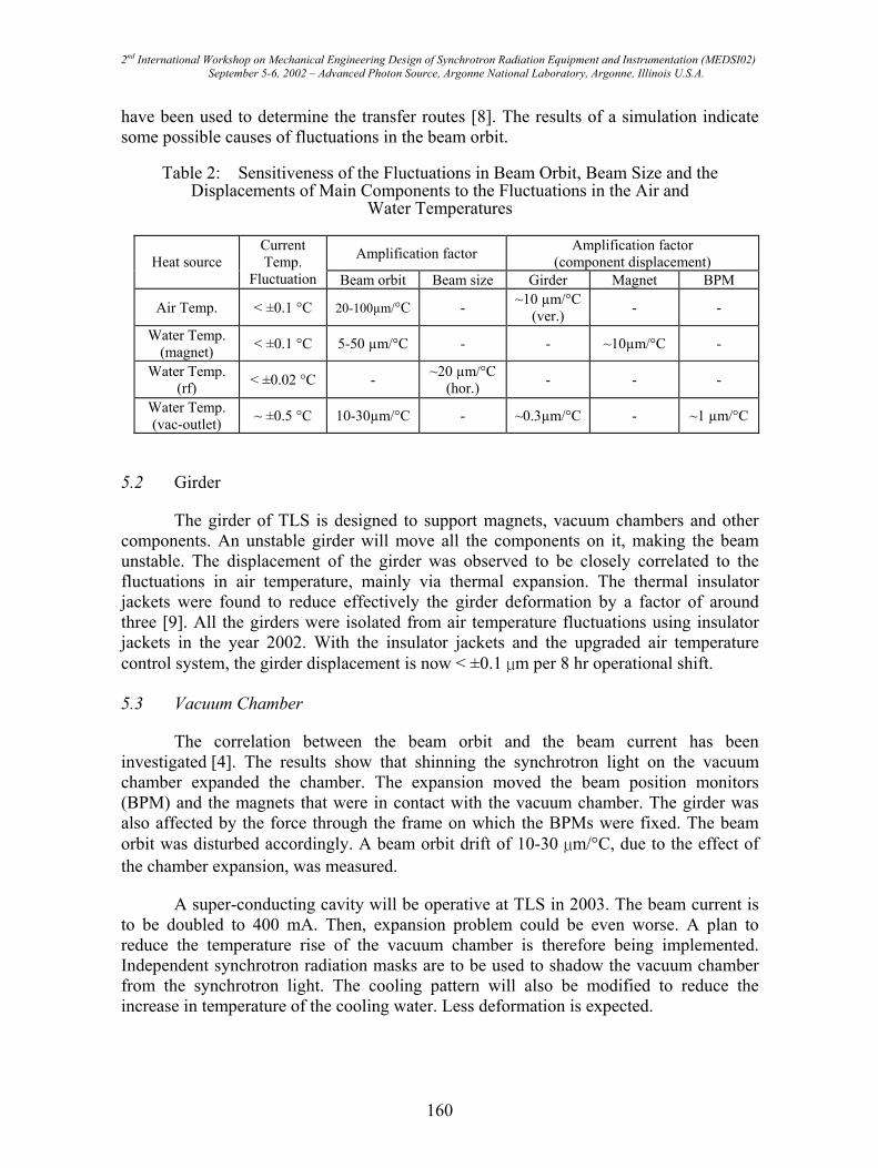
Studies into the thermal-mechanical effects focus largely on identifying the most sensitive mechanical components that translate the thermal forces from heat sources into the fluctuations in the orbit or size of electron beams. Table 2 lists the main components and their sensitiveness to fluctuations in the temperature of the air and water.
The effects of daily variations in the outdoor temperature and the temperature transients following injection were examined in 1998 [3]. Both effects have been minimized by increasing the energy of the injector to 1.5 GeV and by improving the air temperature control system in the storage ring tunnel. Mathematical modeling techniques
159
2nd International Workshop on Mechanical Engineering Design of Synchrotron Radiation Equipment and Instrumentation (MEDSI02) September 5-6, 2002 – Advanced Photon Source, Argonne National Laboratory, Argonne, Illinois U.S.A.
have been used to determine the transfer routes [8]. The results of a simulation indicate some possible causes of fluctuations in the beam orbit.
Table 2: Sensitiveness of the Fluctuations in Beam Orbit, Beam Size and the Displacements of Main Components to the Fluctuations in the Air and
Water Temperatures
Amplification factor Amplification factor (component displacement) Heat source
Current Temp.
Fluctuation Beam orbit Beam size Girder Magnet BPM
Air Temp. < ±0.1 °C 20-100µm/°C - ~10 µm/°C (ver.) - -
Water Temp. (magnet) < ±0.1 °C 5-50 µm/°C - - ~10µm/°C -
Water Temp. (rf) < ±0.02 °C - ~20 µm/°C
(hor.) - - -
Water Temp. (vac-outlet) ~ ±0.5 °C 10-30µm/°C - ~0.3µm/°C - ~1 µm/°C
5.2 Girder
The girder of TLS is designed to support magnets, vacuum chambers and other components. An unstable girder will move all the components on it, making the beam unstable. The displacement of the girder was observed to be closely correlated to the fluctuations in air temperature, mainly via thermal expansion. The thermal insulator jackets were found to reduce effectively the girder deformation by a factor of around three [9]. All the girders were isolated from air temperature fluctuations using insulator jackets in the year 2002. With the insulator jackets and the upgraded air temperature control system, the girder displacement is now < ±0.1 µm per 8 hr operational shift.
5.3 Vacuum Chamber
The correlation between the beam orbit and the beam current has been investigated [4]. The results show that shinning the synchrotron light on the vacuum chamber expanded the chamber. The expansion moved the beam position monitors (BPM) and the magnets that were in contact with the vacuum chamber. The girder was also affected by the force through the frame on which the BPMs were fixed. The beam orbit was disturbed accordingly. A beam orbit drift of 10-30 µm/°C, due to the effect of the chamber expansion, was measured.
A super-conducting cavity will be operative at TLS in 2003. The beam current is to be doubled to 400 mA. Then, expansion problem could be even worse. A plan to reduce the temperature rise of the vacuum chamber is therefore being implemented. Independent synchrotron radiation masks are to be used to shadow the vacuum chamber from the synchrotron light. The cooling pattern will also be modified to reduce the increase in temperature of the cooling water. Less deformation is expected.
160
2nd International Workshop on Mechanical Engineering Design of Synchrotron Radiation Equipment and Instrumentation (MEDSI02) September 5-6, 2002 – Advanced Photon Source, Argonne National Laboratory, Argonne, Illinois U.S.A.
5.4 RF Cavity and Photon Beam Monitor
The cavity is a major heat source of the rf system. The beam size has been found to be quite sensitive to the temperature fluctuations of the DIW in the cavity [5]. The variation in the beam size was significantly reduced after the water temperature fluctuations were reduced to < 0.02 °C.
In the studies on beam size, the temperature of the DIW for the photon beam lines affected the “observed” beam size. The thermally-induced displacement of the mirror was responsible for this observation. A photon beam intensity monitor (ΔI monitor) revealed a similar result. In the ΔI monitor system, not only the mirror itself, but also the mirror chamber and the supporting frame of the monitor, were influenced by the surrounding air/water temperature [10]. After the beam-line DIW temperature stability was improved, a photon beam intensity fluctuation of < 0.3% was achieved. This ΔI value implies a beam size fluctuation of < 0.3 µm. Although the temperature fluctuation of the beam line DIW was reduced to < ±0.2 °C, a correlation is still observed between the temperature fluctuation and the measured photon beam intensity. An independent cooling water system with a temperature fluctuation of < ±0.01 °C is to be implemented for this monitor.
6. Vibration
Several devices, including the overhead crane, AHUs, mechanical pumps, and cooling pipes, have been identified as sources of vibration at TLS. The motion of a 7.5 ton overhead crane seriously distorted the beam orbit [11]. The crane may not be operated while the machine is being operated. Besides, the crane must be in a single location to yield a particular deformation pattern of the storage ring tunnel. Except for that due to the crane, vibration at TLS has not been found to affect greatly the beam stability following the replacement of the worn-out bearings of the AHUs in 1998. However, vibration is becoming a dominant source of noise. The effects of damping materials have been continuously studied and the vibration distribution continually mapped [12]. The air and the cooling water pipes, particularly on the top of the roof of the tunnel, are to be re-supported to reduce vibration. The vibration of the AHUs on the second floor of the core area is to be further damped in the near future.
7. Sensors and Control Systems
7.1 Sensors
Few sensors of the air/water temperature were used during the early operation of TLS. Many air temperature sensors, with a resolution of < 0.1 °C, were installed in the storage ring tunnel in 1997, and revealed a temperature transient during injection. Meanwhile, water temperature sensors were also upgraded to digital one with a resolution of < 0.02 °C. The newly installed water temperature sensors together with the renewed water control system significantly reduced the fluctuation in water temperature. Position sensors, with a resolution of < 0.1 µm, were installed in the second superperiod of the storage ring. The position sensors helped to elucidate the mechanical effects discussed in
161
2nd International Workshop on Mechanical Engineering Design of Synchrotron Radiation Equipment and Instrumentation (MEDSI02) September 5-6, 2002 – Advanced Photon Source, Argonne National Laboratory, Argonne, Illinois U.S.A.
Section 5. Electrical current and voltage transducers were installed recently. Although the main purpose of the electrical sensors is electrical, the electrical data are quite helpful in determining sources of “electrical heating” and in correlating the thermal, mechanical, and the electrical noise.
7.2 Control System
Sensors, valves, pumps and the control system of the water systems were carefully reviewed to improve temperature control [13]. Some parts were replaced because they have an insufficient sensitivity or linearity. The flow rate or the water temperature was adjusted, for some devices, to operate the system at a region of most linear response and to increase the control margin. Variable frequency (VF) controllers were installed for most of the pump drivers. An utility data archive system was also built. Most of the utility data can be accessed through the Internet.
Following the completion of the new Utility Building #2, the CHW capacity for TLS will increase by ~ 40%. A greater CHW capacity will be supplied to the core area and the experimental hall. The present configuration, in which the same AHUs are used for the storage ring tunnel and the experimental hall, will be changed. The AHUs are to be separated by area. Superior air temperature control is expected in these two areas.
8. Summary
Mechanical issues that relate to beam stability at TLS have been investigated. The beam quality was improved in many ways. Sensors were installed, the heat source stabilized, the control system upgraded, thermal-mechanical effects studied, vibrations examined and the cooling capacity increased. Studies have shown that the vibration and temperature fluctuations were the main sources of noise. Via the girder, vacuum chamber, power supply, and the rf cavity, fluctuations in the air/water temperature affected the orbit and size of the electron beam. The photon beam monitor systems were also impacted, leading to misleading interpretations of data.
Following the improvements, the temperature fluctuations of the air and DIW in the tunnel were reduced from > ±1 °C to < ±0.1 °C. The displacement of the girder is now < ±0.1 µm per shift. With the improvement in the global orbit feedback (GFB) system, the beam orbit fluctuation (beam orbit drift per shift) was reduced from ~ 5 µm (> 50 µm) to < 1 µm (< 5 µm w/o GFB and < 3 µm with GFB). The stability of the photon beam intensity (ΔI) has also been improved from > 1% to < 0.3%.
photon beam intensity of ~ 0.1% at a beam current of 400 mA is sought. The AHU configurations are to be modified to reduce further the air temperature fluctuations in the
pipes are to be suppressed. Independent masks are to be installed to reduce the thermal load of the synchrotron light on the vacuum chamber.
experimental hall and the core area. The vibrations due to the AHUs and the air/water
Other work is ongoing to meet the growing demands of users. A stability of the
162

2nd International Workshop on Mechanical Engineering Design of Synchrotron Radiation Equipment and Instrumentation (MEDSI02) September 5-6, 2002 – Advanced Photon Source, Argonne National Laboratory, Argonne, Illinois U.S.A.
9. Acknowledgments
The authors would like thank their colleagues, particularly in the Utility Group and the Mechanical Positioning Group, of the SRRC for their supports in this work.
10. References
[1] R. Keller, H. Nishimura, and the Stability Task Force, “Orbit Stability of the ALS Storage Ring,” LBNL report, LBNL-39796, UC-410, May 1997.
[2] Papers in Proc. of the 1st International workshop on Mechanical Engineering Design of Synchrotron Radiation Equipment and Instrumentation (MEDSI-2000), Paul Scherrer Institute, Switzerland, July 13/14 2000.
[3] J. R. Chen, H. M. Cheng, Z. D. Tsai, C. R. Chen, T. F. Lin, G. Y. Hsiung, and Y. S. Hong, “The Correlation between the Beam Orbit Stability and the Utilities at SRRC,” Proc. of the 6th European Particle Accelerator Conference EPAC’98, Stockholm, (1998).
[4] J.R. Chen, Z.D. Tsai, C.K. Kuan, S.H. Chang, D. Lee, F.Y. Lin and D.J. Wang, “Utility and Mechanical component Stability at SRRC,” Proc. of the MEDSI-2000, Villigen PSI, pp. 91-96 (2000).
[5] J.R. Chen, D.J. Wang, C.K. Kuan, Z.D. Tsai, D.S. Lee, and H.C. Ho, “ Dynamic mechanical consideration for TLS-II,” Proc. of the Shanghai Symposium on Intermediate Energy Light Source (SSIELS-2001), Shanghai, (2001).
[6] C.H. Chang et. al, “Construction and Performance of the Elliptical Polarization Undulator EPU5.6 in SRRC,” Proc. of the Particle Accelerator Conference PAC’99, New York, (1999).
[7] D.S. Lee, Z.D. Tsai, and J.R. Chen, “Mini Environment Control for the Elliptical Polarization Undulator,” Proc. of the Particle Accelerator Conference PAC’01, Chicago, (2001).
[8] H.M. Cheng, C.R. Chen, Z.D. Tsai and J.R. Chen, “Utility Optimization for the Beam Orbit Stability at SRRC,” Proc. of the PAC’99, (1999).
[9] D.J. Wang, H.C. Ho, C.K. Kuan, and J.R. Chen, “Experimental study of thermal deformation of the magnet girder at SRRC storage Ring,” Asian Particle Accelerator Conference (APAC'01), Beijing, September 17-21, 2001.
[10] C.K. Kuan et. al, this proceedings. [11] K.T. Hsu, C.C. Kuo, C. H. Kuo, H.P. Chang, Ch. Wang, H. J. Tsai, J.R. Chen,
K.K. Lin and R.C. Sah, “Beam Orbit Stability at Taiwan Light Source,” Proc. of the PAC’99, New York, (1999).
[12] D.J. Wang, S.Y. Perng, S.-J. Chen, and C.J. Lin, “Comparison of some Commercial Viscoelastic Materials in Vibration Damping,” Proc. of the MEDSI-2000, Villigen PSI, pp.65-76, (2000).
[13] Z.D. Tsai, D.S. Lee, J.C. Chang, Y.C. Chang, and J.R. Chen, “The status of the
17-21, 2001.
utility system stability improvement study at TLS,” APAC’01, Beijing, September
163