Mechanical Properties of Electrospun CNF/PVA Nanofiber ... · Mechanical properties of electrospun...
14
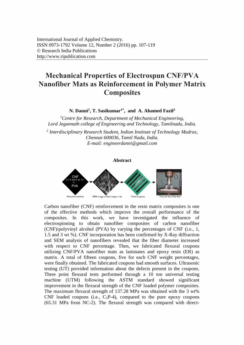
International Journal of Applied Chemistry. ISSN 0973-1792 Volume 12, Number 2 (2016) pp. 107-119 © Research India Publications http://www.ripublication.com Mechanical Properties of Electrospun CNF/PVA Nanofiber Mats as Reinforcement in Polymer Matrix Composites N. Danni 1 , T. Sasikumar 1* , and A. Ahamed Fazil 2 1 Centre for Research, Department of Mechanical Engineering, Lord Jegannath college of Engineering and Technology, Tamilnadu, India. 2 Interdisciplinary Research Student, Indian Institute of Technology Madras, Chennai 600036, Tamil Nadu, India. E-mail: [email protected] Abstract Carbon nanofiber (CNF) reinforcement in the resin matrix composites is one of the effective methods which improve the overall performance of the composites. In this work, we have investigated the influence of electrospinning to obtain nanofiber composites of carbon nanofiber (CNF)/polyvinyl alcohol (PVA) by varying the percentages of CNF (i.e., 1, 1.5 and 3 wt %). CNF incorporation has been confirmed by X-Ray diffraction and SEM analysis of nanofibers revealed that the fiber diameter increased with respect to CNF percentage. Then, we fabricated flexural coupons utilizing CNF/PVA nanofiber mats as laminates and epoxy resin (ER) as matrix. A total of fifteen coupons, five for each CNF weight percentages, were finally obtained. The fabricated coupons had smooth surfaces. Ultrasonic testing (UT) provided information about the defects present in the coupons. Three point flexural tests performed through a 10 ton universal testing machine (UTM) following the ASTM standard showed significant improvement in the flexural strength of the CNF loaded polymer composites. The maximum flexural strength of 137.28 MPa was obtained with the 3 wt% CNF loaded coupons (i.e., C3P-4), compared to the pure epoxy coupons (65.31 MPa from NC-2). The flexural strength was compared with direct-
Transcript of Mechanical Properties of Electrospun CNF/PVA Nanofiber ... · Mechanical properties of electrospun...
International Journal of Applied Chemistry.
ISSN 0973-1792 Volume 12, Number 2 (2016) pp. 107-119
© Research India Publications
http://www.ripublication.com
Mechanical Properties of Electrospun CNF/PVA
Nanofiber Mats as Reinforcement in Polymer Matrix
Composites
N. Danni1, T. Sasikumar1*, and A. Ahamed Fazil2
1Centre for Research, Department of Mechanical Engineering,
Lord Jegannath college of Engineering and Technology, Tamilnadu, India.
2 Interdisciplinary Research Student, Indian Institute of Technology Madras,
Chennai 600036, Tamil Nadu, India.
E-mail: [email protected]
Abstract
Carbon nanofiber (CNF) reinforcement in the resin matrix composites is one
of the effective methods which improve the overall performance of the
composites. In this work, we have investigated the influence of
electrospinning to obtain nanofiber composites of carbon nanofiber
(CNF)/polyvinyl alcohol (PVA) by varying the percentages of CNF (i.e., 1,
1.5 and 3 wt %). CNF incorporation has been confirmed by X-Ray diffraction
and SEM analysis of nanofibers revealed that the fiber diameter increased
with respect to CNF percentage. Then, we fabricated flexural coupons
utilizing CNF/PVA nanofiber mats as laminates and epoxy resin (ER) as
matrix. A total of fifteen coupons, five for each CNF weight percentages,
were finally obtained. The fabricated coupons had smooth surfaces. Ultrasonic
testing (UT) provided information about the defects present in the coupons.
Three point flexural tests performed through a 10 ton universal testing
machine (UTM) following the ASTM standard showed significant
improvement in the flexural strength of the CNF loaded polymer composites.
The maximum flexural strength of 137.28 MPa was obtained with the 3 wt%
CNF loaded coupons (i.e., C3P-4), compared to the pure epoxy coupons
(65.31 MPa from NC-2). The flexural strength was compared with direct-
108 N. Danni, T. Sasikumar and A. Ahamed Fazil
mixed CNF/ER composite coupons (dM-CPs) and found to increase as much
as 46%. The uniform dispersion of CNF/PVA with tunable nanofibers, their
higher surface area and load bearing characteristics could be attributed for this
enhanced strength and these composites may open up numerous possibilities
for industries like defense and automobile.
Keywords: Carbon nanofiber (CNF), poly-vinyl alcohol (PVA), ultra-sonic
scanning, flexural strength and epoxy composites
1. INTRODUCTION Epoxy resin (ER) based matrices have been extensively studied for their tremendous
applications. In the polymeric field, epoxy resins are well predictable thermosetting
matrices presenting a series of remarkable characteristics like excellent stiffness,
specific strength, dimensional strength, chemical resistance and also strong bonding to
the reinforcement [1]. It has been extensively used in the areas such as electronics and
astronautics industries. Still, there is a big space for research to enhance the overall
performance of the epoxy resin matrices by introducing new reinforcements. The
emergence of nanotechnology gives positive approaches which could solve the
existing problems faced in macroscale levels. Especially, the use of nano-fillers such
as Carbon nanotubes (CNTs) and Carbon Nanofibers (CNFs) can provide improved
properties for the epoxy resin matrix.
Carbon nanofibers (CNFs), due to their better tensile strength, thermal, mechanical
and electric properties, have been widely used for polymer reinforcement techniques
[2]. CNFs have been used as the reinforcement materials in polymers like
polyethylene [3], nylon [4], and polycarbonate [5] and are preferred for their high
temperature resistance, good thermal and mechanical properties. CNFs are widely
preferred for high load bearing applications. Many studies have demonstrated the bare
inclusion of CNFs onto the resin matrix but little effort has been made to electrospun
the CNFs and thereby evaluating its performance.
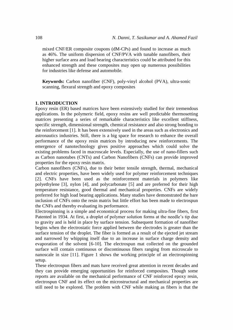
Electrospinning is a simple and economical process for making ultra-fine fibers, first
Patented in 1934. At first, a droplet of polymer solution forms at the needle’s tip due
to gravity and is held in place by surface tension. Subsequent formation of nanofiber
begins when the electrostatic force applied between the electrodes is greater than the
surface tension of the droplet. The fiber is formed as a result of the ejected jet stream
and narrowed by whipping itself due to an increase in surface charge density and
evaporation of the solvent [6-10]. The electrospun mat collected on the grounded
surface will contain continuous or discontinuous fibers ranging from microscale to
nanoscale in size [11]. Figure 1 shows the working principle of an electrospinning
setup.
These electrospun fibers and mats have received great attention in recent decades and
they can provide emerging opportunities for reinforced composites. Though some
reports are available on the mechanical performance of CNF reinforced epoxy resin,
electrospun CNF and its effect on the microstructural and mechanical properties are
still need to be explored. The problem with CNF while making as fibers is that the
Mechanical properties of electrospun CNF/PVA nanofiber mats 109
direct electrospinning of crude CNF solution does not give uniform fiber networks
and spreads only beads. So we have planned to electrospun CNFs using a supporting
polymer Polyvinyl alcohol (PVA) and identify the effect of the electrospun CNFs
over the conventional mixing of both CNF and Epoxy resin (CNF/ER).
For mechanical strength comparision, direct blending of CNF with Epoxy resin
matrix, without PVA, was executed and in order to investigate the efficacy of
electrospinning over direct mixing of solutions. So, both the CNF/PVA nanofiber
mats and CNF/ER composites have been prepared as flexural coupons (CP and dM-
CP coupons respectively) of same dimension and their flexural analysis were carried
out in a 10 ton universal testing machine as per ASTM standards. Also, the
concentration of CNF loading onto PVA was varied and its effect over the flexural
strength was discussed. The microstructure of electrospun CNF/PVA nanofibers,
structural features were studied and defects in the fabricated coupons, their effects on
final flexural strength of the composites were simultaneously investigated.
Figure 1: The schematic diagram of electrospinning setup describing its working
mechanism
2. EXPERIMENTAL PROCEDURE
2.1. Materials
Polyvinyl alcohol (PVA) of average molecular weight of 85, 000-1, 24000 was
obtained (Central drug house (p) ltd) and used without further purification. Araldite
standard epoxy resin (CY 230-1, HUNTSMAN) and hardener (Aradur HY 951) were
purchased (Leo Enterprises Ltd) and directly used. Carbon nanofibers (CNF) (Sigma
Aldrich) used in this study were of 100 nm in diameter, 20-200µm long and of >98%
carbon basis.

110 N. Danni, T. Sasikumar and A. Ahamed Fazil
2.2. Electrospinning of CNF/PVA mat
A homogenous solution of PVA and CNF was obtained by dissolving them in
ethanol/water mixture. Different weight ratio of CNF is added with PVA to obtain the
final solution. In CNF/PVA mixture, the weight percentage of CNF is varied from 1,
1.5 and 3; and mixed with the respective amount of PVA maintaining the final
concentration to 10 wt. % for all samples. The solutions were stirred under a
temperature controlled magnetic stirrer at 60˚C for 4 hours. The solutions were further
sonicated for 120 s at room temperature. These solutions were utilized as polymer
precursors for the electrospinning process using the ESpin-Nano apparatus (PICO
India).
During the electrospinning process, the as prepared polymer solutions were pumped
from a 2.5 ml syringe attached with a hypodermic needle of 0.1mm inner diameter. A
voltage supply of 10kV was applied between the two electrodes which accelerated the
formation of polymer jet from CNF/PVA polymer solution at the needle’s tip (as
depicted in Fig.1). The syringe holding the polymer solution was pumped through a
microcontroller pump with a feed rate of 1 mlh-1. With the same electrospinning
parameters, all the three different CNF/PVA composites had been successfully spun
and they are labeled as C1P (1 wt. % of CNF), C1.5P (1.5 wt. % of CNF) and C3P (3
wt. % of CNF). A total of 24 CNF/PVA nanofiber mats from three solution
compositions were obtained. The length and width of the obtained mats were of 100
mm and 130 mm respectively. The thickness of each mat was of 0.09 mm. The digital
images of the as-obtained CNF/PVA nanofiber mats are presented in figure 2.
Figure 2: The digital images of CNF/PVA electrospun mats C1P (a) C1.5P (b) and C3P
(c) (all the three samples possess the same dimension as mentioned in ‘a’)
2.3. Fabrication of epoxy resin coupon incorporating CNF/PVA nanofiber mats
CNF/PVA nanofiber mats were mixed with epoxy resin matrix through a layer by
layer (as laminate materials within matrix by hand lay-up method) technique to make
the final flexural coupons. The hand lay-up method is the simplest method for
composite molding, which is depicted in figure 3(a).

Mechanical properties of electrospun CNF/PVA nanofiber mats 111
Figure 3: Hand lay-up method for forming the composite (a) and digital image of a
flexural coupon (C1.5P) during the fabrication process (b)
Pure epoxy resin and CNF/PVA nanofiber mats were utilized to fabricate the flexural
coupons and pure epoxy resin coupons (Neat Coupons-NC) were prepared
concurrently to be used as control samples. The epoxy resin was fabricated using CY
230-1 epoxy with the hardener HY951. The final matrix was cured at room
temperature. For each flexural coupon, total of eight nanofiber CNF/PVA mats from
the respective CNF weight percentage was used (depicted in Fig. 3(b)). Finally, three
full coupons with the dimension of 100*130*2 mm (length, width and thickness
respectively) were obtained. They were cut by using diamond cutter avoiding any
edge damage. Each Full coupon was again cut into five small coupons with the
dimension of 80*25 mm (length and width respectively). The as-fabricated flexural
coupons are shown in figure 4 (a) & (b). The final thickness of the flexural coupons
was 2 mm for all the samples. The overall process for obtaining the final flexural
coupons is presented as a schematic in Fig. 5.
Figure 4: Pure epoxy resin coupons (NC) (a) and the as-fabricated CNF/PVA
nanofiber mat reinforced final flexural coupons from various
CNF weight percentages (b)

112 N. Danni, T. Sasikumar and A. Ahamed Fazil
Figure 5: Schematic illustration describing the steps involved in fabricating flexural
coupons and their mechanical testing
2.4. Fabrication of direct-mixed CNF/ER coupons
Pure epoxy resin and CNFs were directly blended to fabricate the flexural coupons
(dM-CPs). CNF of 0.1gram is blended with epoxy resin (ER) and total of 5 coupons
were fabricated and made sure their dimensions (100*130*2 mm) were consistent
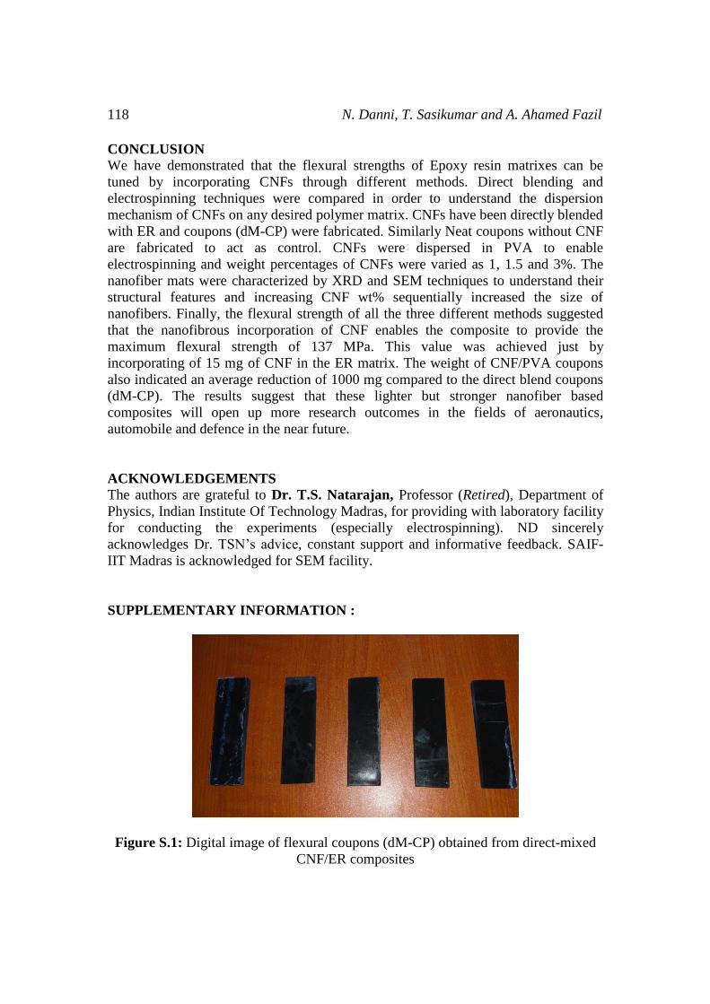
with their counterparts (NCs and CPs). The photographic image of as fabricated dM-
CP coupons were represented in Fig-S1 (see Supplementary Information)
2.5. Characterization The crystal structure of the CNF/PVA electrospun nanofiber mats was analyzed by
PANalytical X’pert Pro equipment available at the Department of Physics, IIT
Madras. The X-ray tube was operating at 40 kV with the Cukα radiation source with a
wavelength of 0.154 nm. The scan was done over the range of 10 to 80° degree with
the step aped of 0.016° per second.The morphologies of the nanofibers were
examined by a FEI-Quanta (FEG) (available at SAIF-IIT Madras). The mats were
sputter coated before the analysis.
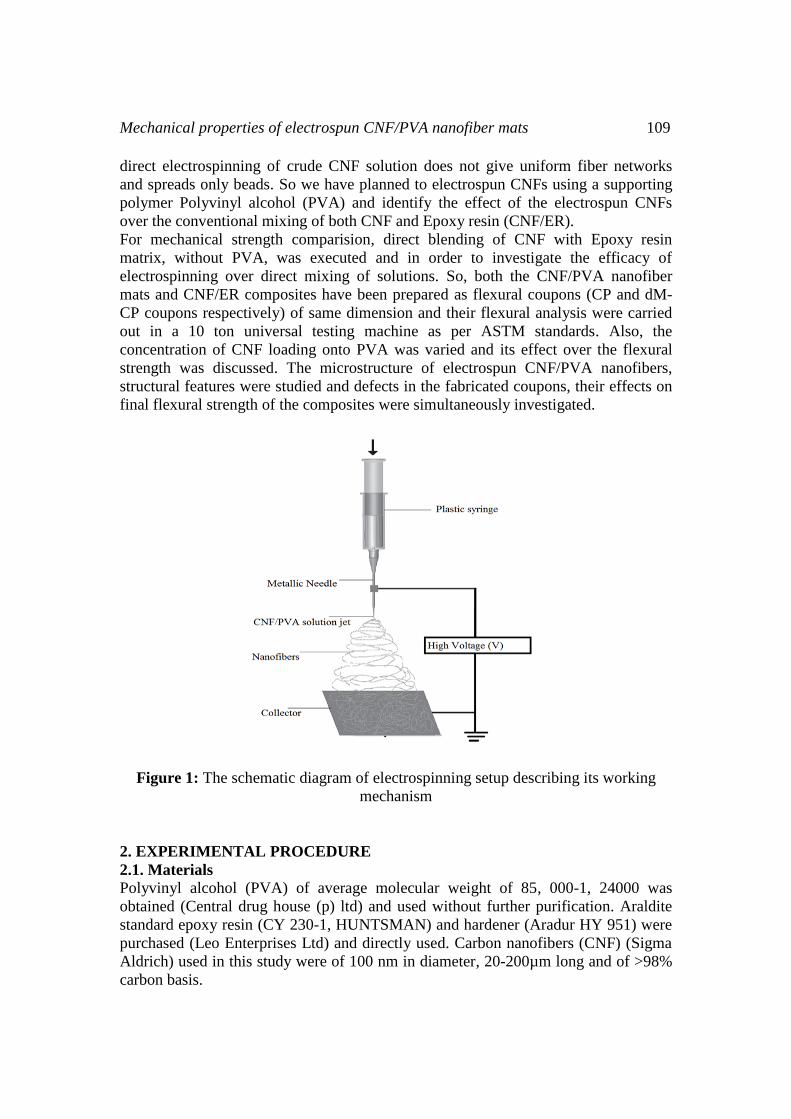
2.5.1. Pulse-echo ultrasonic testing:
Ultrasonic testing (UT) was carried out according to USM 35 specifications. UT is a
versatile inspection method to identify the internal and external flaws in the material.
In the setup, a transducer sends out a pulse of energy and receives the energy back.
Reflection occurs due to the presence of discontinuities and the surface of the test
sample. The amount of reflected sound energy is displayed with the change of time,
which provides the inspected information about the size and the location of the flaws
as shown in figure 6.
UT is conducted on all coupons to identify the defect. The defects identified from the
surface and interior of the coupons are represented as a table (table-2).
Mechanical properties of electrospun CNF/PVA nanofiber mats 113
Figure 6: Working principle of an ultrasonic testing
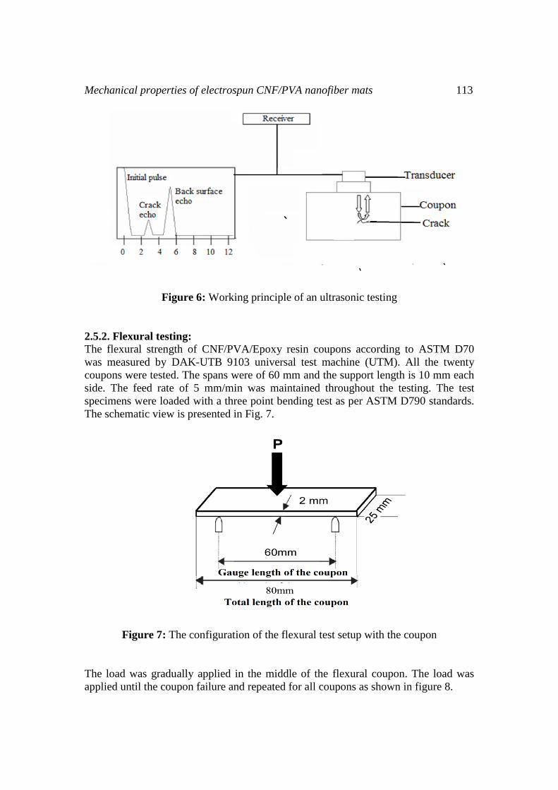
2.5.2. Flexural testing:
The flexural strength of CNF/PVA/Epoxy resin coupons according to ASTM D70
was measured by DAK-UTB 9103 universal test machine (UTM). All the twenty
coupons were tested. The spans were of 60 mm and the support length is 10 mm each
side. The feed rate of 5 mm/min was maintained throughout the testing. The test
specimens were loaded with a three point bending test as per ASTM D790 standards.
The schematic view is presented in Fig. 7.
Figure 7: The configuration of the flexural test setup with the coupon
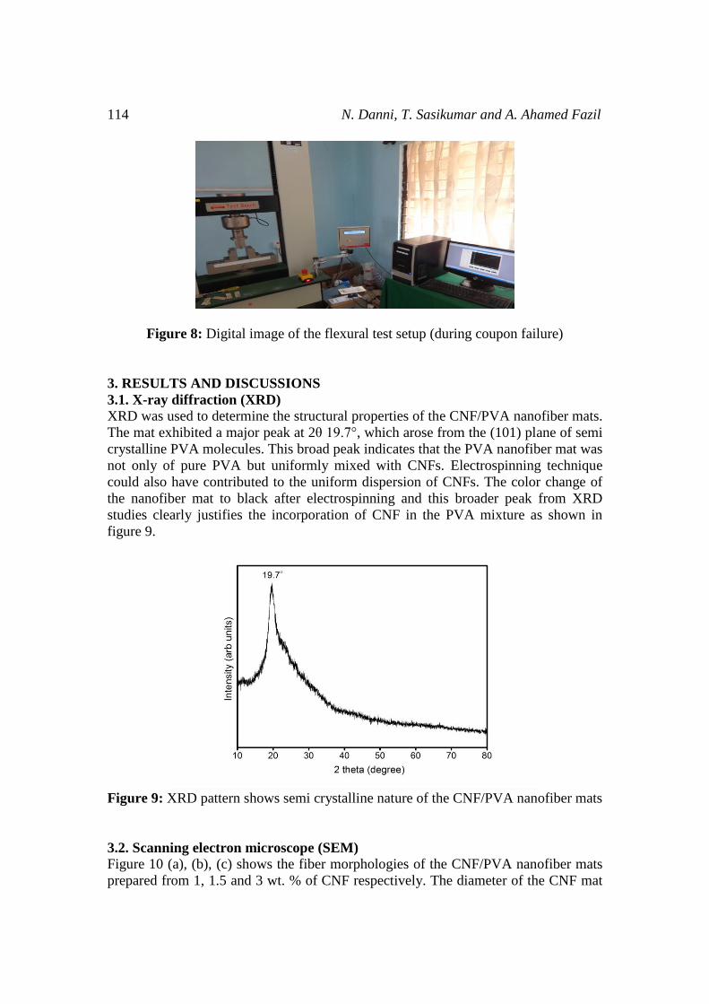
The load was gradually applied in the middle of the flexural coupon. The load was
applied until the coupon failure and repeated for all coupons as shown in figure 8.
114 N. Danni, T. Sasikumar and A. Ahamed Fazil
Figure 8: Digital image of the flexural test setup (during coupon failure)
3. RESULTS AND DISCUSSIONS
3.1. X-ray diffraction (XRD) XRD was used to determine the structural properties of the CNF/PVA nanofiber mats.
The mat exhibited a major peak at 2θ 19.7°, which arose from the (101) plane of semi
crystalline PVA molecules. This broad peak indicates that the PVA nanofiber mat was
not only of pure PVA but uniformly mixed with CNFs. Electrospinning technique
could also have contributed to the uniform dispersion of CNFs. The color change of
the nanofiber mat to black after electrospinning and this broader peak from XRD
studies clearly justifies the incorporation of CNF in the PVA mixture as shown in
figure 9.
Figure 9: XRD pattern shows semi crystalline nature of the CNF/PVA nanofiber mats
3.2. Scanning electron microscope (SEM)
Figure 10 (a), (b), (c) shows the fiber morphologies of the CNF/PVA nanofiber mats
prepared from 1, 1.5 and 3 wt. % of CNF respectively. The diameter of the CNF mat
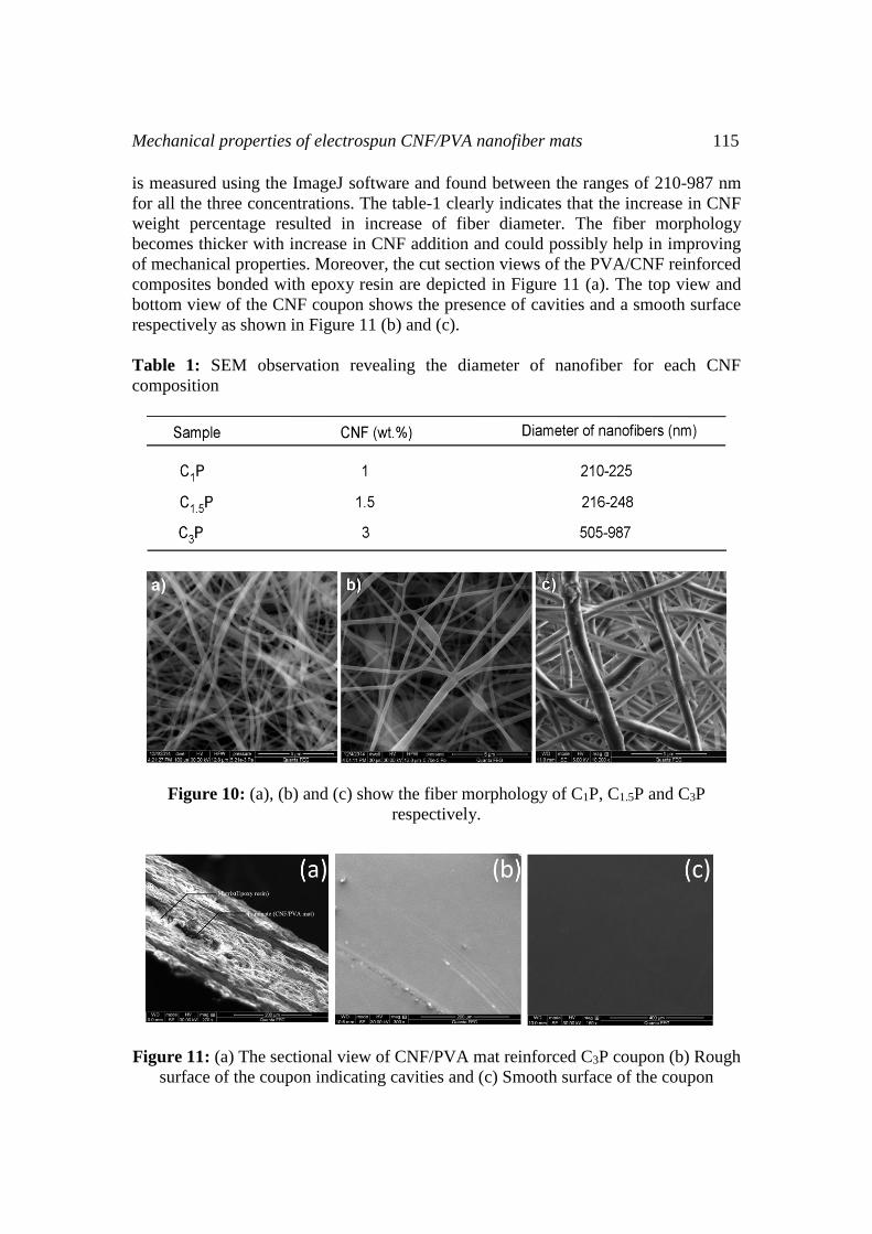
Mechanical properties of electrospun CNF/PVA nanofiber mats 115
is measured using the ImageJ software and found between the ranges of 210-987 nm
for all the three concentrations. The table-1 clearly indicates that the increase in CNF
weight percentage resulted in increase of fiber diameter. The fiber morphology
becomes thicker with increase in CNF addition and could possibly help in improving
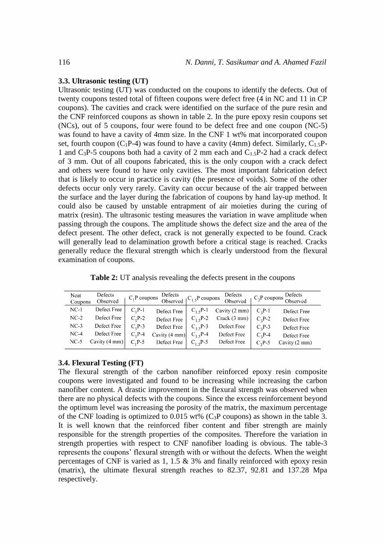
of mechanical properties. Moreover, the cut section views of the PVA/CNF reinforced
composites bonded with epoxy resin are depicted in Figure 11 (a). The top view and
bottom view of the CNF coupon shows the presence of cavities and a smooth surface
respectively as shown in Figure 11 (b) and (c).
Table 1: SEM observation revealing the diameter of nanofiber for each CNF
composition
Figure 10: (a), (b) and (c) show the fiber morphology of C1P, C1.5P and C3P
respectively.
Figure 11: (a) The sectional view of CNF/PVA mat reinforced C3P coupon (b) Rough
surface of the coupon indicating cavities and (c) Smooth surface of the coupon
116 N. Danni, T. Sasikumar and A. Ahamed Fazil
3.3. Ultrasonic testing (UT)
Ultrasonic testing (UT) was conducted on the coupons to identify the defects. Out of
twenty coupons tested total of fifteen coupons were defect free (4 in NC and 11 in CP
coupons). The cavities and crack were identified on the surface of the pure resin and
the CNF reinforced coupons as shown in table 2. In the pure epoxy resin coupons set
(NCs), out of 5 coupons, four were found to be defect free and one coupon (NC-5)
was found to have a cavity of 4mm size. In the CNF 1 wt% mat incorporated coupon
set, fourth coupon (C1P-4) was found to have a cavity (4mm) defect. Similarly, C1.5P-
1 and C3P-5 coupons both had a cavity of 2 mm each and C1.5P-2 had a crack defect
of 3 mm. Out of all coupons fabricated, this is the only coupon with a crack defect
and others were found to have only cavities. The most important fabrication defect
that is likely to occur in practice is cavity (the presence of voids). Some of the other
defects occur only very rarely. Cavity can occur because of the air trapped between
the surface and the layer during the fabrication of coupons by hand lay-up method. It
could also be caused by unstable entrapment of air moieties during the curing of
matrix (resin). The ultrasonic testing measures the variation in wave amplitude when
passing through the coupons. The amplitude shows the defect size and the area of the
defect present. The other defect, crack is not generally expected to be found. Crack
will generally lead to delamination growth before a critical stage is reached. Cracks
generally reduce the flexural strength which is clearly understood from the flexural
examination of coupons.
Table 2: UT analysis revealing the defects present in the coupons
3.4. Flexural Testing (FT)
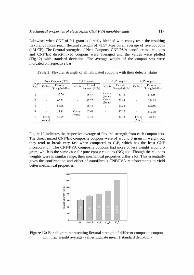
The flexural strength of the carbon nanofiber reinforced epoxy resin composite
coupons were investigated and found to be increasing while increasing the carbon
nanofiber content. A drastic improvement in the flexural strength was observed when
there are no physical defects with the coupons. Since the excess reinforcement beyond
the optimum level was increasing the porosity of the matrix, the maximum percentage
of the CNF loading is optimized to 0.015 wt% (C3P coupons) as shown in the table 3.
It is well known that the reinforced fiber content and fiber strength are mainly
responsible for the strength properties of the composites. Therefore the variation in
strength properties with respect to CNF nanofiber loading is obvious. The table-3
represents the coupons’ flexural strength with or without the defects. When the weight
percentages of CNF is varied as 1, 1.5 & 3% and finally reinforced with epoxy resin
(matrix), the ultimate flexural strength reaches to 82.37, 92.81 and 137.28 Mpa
respectively.
Mechanical properties of electrospun CNF/PVA nanofiber mats 117
Likewise, when CNF of 0.1 gram is directly blended with epoxy resin the resulting
flexural coupons reach flexural strength of 73.57 Mpa on an average of five coupons
(dM-CP). The flexural strengths of Neat Coupons, CNF/PVA nanofiber mat coupons
and CNF/ER direct-mixed coupons were averaged and the values were plotted
(Fig.12) with standard deviation. The average weight of the coupon sets were
indicated on respective bar.
Table 3: Flexural strength of all fabricated coupons with their defects’ status
Figure 12 indicates the respective average of flexural strength from each coupon sets.
The direct mixed CNF/ER composite coupons were of around 6 gram in weight but
they tend to break very fast when compared to C1P, which has the least CNF
incorporation. The CNF/PVA composite coupons had more or less weight around 5
gram, which is the same case for pure epoxy coupons (NC) too. Though the coupons
weights were in similar range, their mechanical properties differ a lot. This essentially
gives the confirmation and effect of nanofibrous CNF/PVA reinforcements to yield
better mechanical properties.
Figure 12: Bar diagram representing flexural strength of different composite coupons
with their weight average (values indicate mean ± standard deviation)
118 N. Danni, T. Sasikumar and A. Ahamed Fazil
CONCLUSION
We have demonstrated that the flexural strengths of Epoxy resin matrixes can be
tuned by incorporating CNFs through different methods. Direct blending and
electrospinning techniques were compared in order to understand the dispersion
mechanism of CNFs on any desired polymer matrix. CNFs have been directly blended
with ER and coupons (dM-CP) were fabricated. Similarly Neat coupons without CNF
are fabricated to act as control. CNFs were dispersed in PVA to enable
electrospinning and weight percentages of CNFs were varied as 1, 1.5 and 3%. The
nanofiber mats were characterized by XRD and SEM techniques to understand their
structural features and increasing CNF wt% sequentially increased the size of
nanofibers. Finally, the flexural strength of all the three different methods suggested
that the nanofibrous incorporation of CNF enables the composite to provide the
maximum flexural strength of 137 MPa. This value was achieved just by
incorporating of 15 mg of CNF in the ER matrix. The weight of CNF/PVA coupons
also indicated an average reduction of 1000 mg compared to the direct blend coupons
(dM-CP). The results suggest that these lighter but stronger nanofiber based
composites will open up more research outcomes in the fields of aeronautics,
automobile and defence in the near future.
ACKNOWLEDGEMENTS
The authors are grateful to Dr. T.S. Natarajan, Professor (Retired), Department of
Physics, Indian Institute Of Technology Madras, for providing with laboratory facility
for conducting the experiments (especially electrospinning). ND sincerely
acknowledges Dr. TSN’s advice, constant support and informative feedback. SAIF-
IIT Madras is acknowledged for SEM facility.
SUPPLEMENTARY INFORMATION :
Figure S.1: Digital image of flexural coupons (dM-CP) obtained from direct-mixed
CNF/ER composites

Mechanical properties of electrospun CNF/PVA nanofiber mats 119
REFERENCES
[1] Filatov.Y, Budyka.A., Kirichenko.V, “Electrospinning of Micro-and
Nanofibers: Fundamentals in Separation and Filtration Processes”. Begell
House, Inc, Redding, CT, PP. 443, 2007.
[2] Ramakrishna.S, Teo.W. E, “ A review of electrospinning design and nanofibre
assemblies”. Nanotechnology, Vol. 17 (14), pp-R89−R106, 2000.
[3] Reneker.D.H, Yarin.A. L, Zussman.E, Xu. H. “Electrospinning of Nanofibers
from Polymer Solutions and Melts”. Advances in Applied Mechanics,
Elsevier: New York, Vol. 41, pp 43−195, 2007.
[4] Rutledge.G. C, Fridrikh.S.V. “Formation of fibers by electrospinning”. Adv.
Drug Delivery Rev, Vol. 59 (14), pp-1384−1391, 2007.
[5] Li.D, Xia. Y. “Electrospinning of nanofibers, Reinventing the wheel”,
Advanced Materials, Vol.16, No.14, pp-1151-1170, 2004b.
[6] Ding.B, wang.M, wang.X, Yu.J, Sun G. “Electrospun nano materials for ultra
sensitive sensors Materials”. Today, Vol. 13(11), pp-16-27, 2010.
[7] Kim I-D, Rothschild A. “Nanostructured metal oxide gas sensors prepared by
electrospinning” Polymers for Advanced Technologies, Vol.22(3), pp-318-
325, 2011.
[8] Ding.B, Wang. M, Yu.J, Sun.G. “Gas sensors based on electrospun
nanofibers”. Sensors.Vol.9(3), pp-1609-1624, 2009.
[9] Hammel.E, Tang.X, Trampert.M, Schmitt. T, Mauthner. K, Eder A. “Carbon
nanofibers for composite applications”. Carbon, Vol-42 (5-6), pp-1153-1158,
2004.
[10] Lozano K, Yang S, Zeng Q. “Rheological analysis of vapor-grown carbon
nanofiber reinforced polyethylene composites”. J. Appl. Poly. Sc, Vol-93, pp-
155-162, 2004.
[11 Pogue. RT, Ye. J, Klosterman. DA, Glass.AS, Chartoff. RP.“Evaluating fiber-
matrix interaction in polymer-matrix composites by inverse gas
chromatography”. Composites: Part A, Vol-29, pp-1273-1281, 1998.
[12] Carneiro.OS, Covas.JA, Bernardo. CA, Caldeira G, Van Hattum FWJ, Ting
JM, Alig RL et al. “Production and assessment of polycarbonate composites
reinforced with vapor-grown carbon nanofibers”. Composites Sc. Tech., Vol-
58, pp-401-407, 1998.
[13] Smith Jr. JG, Connell JW, Hergenrother PM, Yokota R, Criss JM. “High
temperature transfer molding resins based on 2, 3, 3’, 4’-
biphenyltetracarboxylic dianhydride”. Soc. Adv. Mat. Proc. Eng. Ser, Vol-47,
pp-316, 2002,.
[14] Smith. Jr. JG, Connell.JW, Hergenrother. PM, Ford. LA, Criss.JM, “Transfer
molding imide resins based on 2, 3, 3, 4-biphenyltetracarboxylic dianhydride”.
Macromol. Symp, vol-199: pp-401, 2003.
[15] Hou.H, Reneker.DH. “Carbon nanotubes on carbon nanofibers: a novel
structure based on electrospun polymer nanofibers”. Adv Mater;Vol-16(1), pp-
69-73, 2004.
120 N. Danni, T. Sasikumar and A. Ahamed Fazil