
Mechanical Properties of Advanced Gas-Cooled Reactor ...clok.uclan.ac.uk/22136/1/22136...
9
Article Mechanical Properties of Advanced Gas-Cooled Reactor Stainless Steel Cladding After Irradiation Degueldre, Claude, Fahy, James, Kolosov, Oleg, Wilbraham, Richard J., Döbeli, Max, Renevier, Nathalie, Ball, Jonathan and Ritter, Stefan Available at http://clok.uclan.ac.uk/22136/ Degueldre, Claude ORCID: 0000-0003-1858-7519, Fahy, James, Kolosov, Oleg ORCID: 0000- 0003-3278-9643, Wilbraham, Richard J., Döbeli, Max, Renevier, Nathalie ORCID: 0000-0003- 2471-7236, Ball, Jonathan and Ritter, Stefan ORCID: 0000-0003-4430-4877 (2018) Mechanical Properties of Advanced Gas-Cooled Reactor Stainless Steel Cladding After Irradiation. Journal of Materials Engineering and Performance, 27 (5). pp. 2081-2088. ISSN 1059-9495 It is advisable to refer to the publisher’s version if you intend to cite from the work. http://dx.doi.org/10.1007/s11665-018-3323-9 For more information about UCLan’s research in this area go to http://www.uclan.ac.uk/researchgroups/ and search for <name of research Group>. For information about Research generally at UCLan please go to http://www.uclan.ac.uk/research/ All outputs in CLoK are protected by Intellectual Property Rights law, including Copyright law. Copyright, IPR and Moral Rights for the works on this site are retained by the individual authors and/or other copyright owners. Terms and conditions for use of this material are defined in the http://clok.uclan.ac.uk/policies/ CLoK Central Lancashire online Knowledge www.clok.uclan.ac.uk
Transcript of Mechanical Properties of Advanced Gas-Cooled Reactor ...clok.uclan.ac.uk/22136/1/22136...

Article
Mechanical Properties of Advanced GasCooled Reactor Stainless Steel Cladding After Irradiation
Degueldre, Claude, Fahy, James, Kolosov, Oleg, Wilbraham, Richard J., Döbeli, Max, Renevier, Nathalie, Ball, Jonathan and Ritter, Stefan
Available at http://clok.uclan.ac.uk/22136/
Degueldre, Claude ORCID: 0000000318587519, Fahy, James, Kolosov, Oleg ORCID: 0000000332789643, Wilbraham, Richard J., Döbeli, Max, Renevier, Nathalie ORCID: 0000000324717236, Ball, Jonathan and Ritter, Stefan ORCID: 0000000344304877 (2018) Mechanical Properties of Advanced GasCooled Reactor Stainless Steel Cladding After Irradiation. Journal of Materials Engineering and Performance, 27 (5). pp. 20812088. ISSN 10599495
It is advisable to refer to the publisher’s version if you intend to cite from the work.http://dx.doi.org/10.1007/s11665-018-3323-9
For more information about UCLan’s research in this area go to http://www.uclan.ac.uk/researchgroups/ and search for <name of research Group>.
For information about Research generally at UCLan please go to http://www.uclan.ac.uk/research/
All outputs in CLoK are protected by Intellectual Property Rights law, includingCopyright law. Copyright, IPR and Moral Rights for the works on this site are retained by the individual authors and/or other copyright owners. Terms and conditions for use of this material are defined in the http://clok.uclan.ac.uk/policies/
CLoKCentral Lancashire online Knowledgewww.clok.uclan.ac.uk

Mechanical Properties of Advanced Gas-Cooled ReactorStainless Steel Cladding After Irradiation
Claude Degueldre, James Fahy, Oleg Kolosov, Richard J. Wilbraham, Max Dobeli, Nathalie Renevier, Jonathan Ball, and Stefan Ritter
(Submitted December 12, 2017; in revised form February 11, 2018)
The production of helium bubbles in advanced gas-cooled reactor (AGR) cladding could represent asignificant hazard for both the mechanical stability and long-term storage of such materials. However, thehigh radioactivity of AGR cladding after operation presents a significant barrier to the scientific study ofthe mechanical properties of helium incorporation, said cladding typically being analyzed in industrial hotcells. An alternative non-active approach is to implant He2+ into unused AGR cladding material via anaccelerator. Here, a feasibility study of such a process, using sequential implantations of helium in AGRcladding steel with decreasing energy is carried out to mimic the buildup of He (e.g., 50 appm) that wouldoccur for in-reactor AGR clad in layers of the order of 10 lm in depth, is described. The implanted sampleis subsequently analyzed by scanning electron microscopy, nanoindentation, atomic force and ultrasonicforce microscopies. As expected, the irradiated zones were affected by implantation damage (< 1 dpa).Nonetheless, such zones undergo only nanoscopic swelling and a small hardness increase (� 10%), with noappreciable decrease in fracture strength. Thus, for this fluence and applied conditions, the integrity of thesteel cladding is retained despite He2+ implantation.
Keywords atomic force microscopy, hardness, helium implanta-tion, nanoindentation, stainless steel
1. Introduction
Since the start of the 1970s, the UK has operated a fleet ofnuclear reactors quite different to the light-water moderatedreactors (LWR) typically found across the rest of the world. Theadvanced gas-cooled reactor (AGR) uses a graphite core andCO2 cooling with an annular in shape, slightly enriched (up to3.5% U235) uranium dioxide-based fuel clad in stainless steelrather than Zircalloy.
This cladding is rich in both nickel (� 25 wt.%) andchromium (� 20 wt.%) in order to withstand high gas temper-atures (Ref 1). However, during in-reactor irradiation heliumgas bubbles are generated by three different interaction routeswith common elements within the steel. First, via neutronirradiation, nickel isotopes may undergo neutron capture.Among them, 58Ni (68% abundance in natural nickel) reactswith a neutron producing 59Ni that after a second neutroncapture yields an alpha particle which becomes helium.
For thermal neutrons, the cross sections of the first andsecond reaction are, respectively, 4 and 12 barns. Initially,Greenwood et al. (Ref 2) compared the measured andcalculated helium production in nickel using new evaluatedcross sections for 59Ni. Later, Gopalakrishnan et al. (Ref 3)compared the calculated helium production obtained by neutronirradiation in stainless steel with that found experimentally.
Secondly, thermal neutrons may react with 10B, producingHe density that can be quantified using the neutron absorptionrelationship buildup with time.
For the reactor flux and the irradiation time, the contributionreaction is then given by the ratio of the density, flux and crosssection of the absorbing nuclide. For the case of an nuclearsteel, the impact of bore is negligible.
Finally, fast neutrons may also react with transition metalisotopes. However, within the AGR reactor, their flux is smallerthan the thermal neutron flux. Furthermore, the cross section offast neutron M(n,a) reactions is also smaller making thisproduction path slower than He production by thermalneutrons.
The so generated helium segregates at grain boundaries andcan act as nucleation sites for embrittlement (Ref 4, 5). Suchembrittlement results in a reduction in the energy to fracture,due to a reduction in strain hardening (as hardening is alreadyoccurring during irradiation). This is motivated by very similarreasons to those that cause radiation hardening, i.e., develop-ment of defect clusters, dislocations, voids and precipitates.Variations in these parameters make the exact amount ofembrittlement difficult to predict, but the generalized values forthe measurement show predictable consistency (Ref 6).
Historically, mechanical testing via microscopy and simplehardness testing has been found to be a suitable way ofdetermining the effects of helium-initiated embrittlement andhow (if at all) the integrity of AGR clad is compromised. Earlystudies by Madden and Callen (Ref 7) used electronmicroscopy to investigate the microstructure of neutron irradi-ated 20Cr/25Ni/TiN austenitic stainless steel after irradiation at
Claude Degueldre and Richard J. Wilbraham, EngineeringDepartment, Lancaster University, Lancaster LA1 4YW, UK;James Fahy, Engineering Department, Lancaster University,Lancaster LA1 4YW, UK; and Jost Institute, University of CentralLancashire, Preston PR1 2HE, UK; Oleg Kolosov, PhysicsDepartment, Lancaster University, Lancaster LA1 4BA, UK;Max Dobeli, Laboratory of Ion Beam Physics, ETH Zurich, 8093Zurich, Switzerland; Nathalie Renevier, Jost Institute, University ofCentral Lancashire, Preston PR1 2HE, UK; Jonathan Ball,EDF-Energy, Fuel Group CTO, Barnwood, Gloucester GL4 3RS,UK; and Stefan Ritter, Laboratory of Nuclear Materials, Paul ScherrerInstitute, 5232 Villigen, Switzerland. Contact e-mail:[email protected].
JMEPEG �The Author(s)https://doi.org/10.1007/s11665-018-3323-9 1059-9495/$19.00
Journal of Materials Engineering and Performance

783 K to a neutron fluence of 5.0 9 1024 m�2 (thermal) and2.5 9 1024 m�2 (fast). The austenitic matrix was free ofirradiation-induced damage, while the TiN particles containednanoloops which coarsened into a network upon annealing at1083 K. Annealing also resulted in a low density of transmu-tation-induced helium bubbles, � 4 nm in diameter, located inprecipitate-free regions of grain boundaries. The material wasfound to be relatively unaffected by irradiation at these fluencelevels, and helium bubble embrittlement was unlikely undernormal stresses.
Following on from this, Odette and Lucas (Ref 8) tested theeffects of intermediate temperature irradiation on the mechan-ical behavior of several austenitic stainless steels. Theydescribed how visible irradiation-induced features are predom-inantly helium bubbles and dislocation loops. Further, theuniform elongation is reduced to less than 1% due to thedecrease in strain hardening and severe flow localizationfollowing irradiation.
Since 1991 several other steel types have been tested byvarious authors. Hashimoto et al. (Ref 9) studied mixed-spectrum irradiation on ferritic/martensitic steels, as well asinvestigating the pros and cons of nickel and boron doping toproduce helium embrittlement.
Review on the analysis of helium effects has been reportedby Klueh et al. (Ref 10). The same year, Yamamoto et al. (Ref11) reported on the effects of irradiation and helium on the yieldstress changes and hardening and non-hardening embrittlementof martensitic steels.
Pouchon et al. (Ref 12) used x-ray absorption spectroscopyto study irradiated oxide dispersion strengthened steels. Finally,Cammelli et al. (Ref 13) investigated a neutron irradiatedreactor pressure vessel steel by x-ray absorption spectroscopy.
However, since these studies, characterization studies onstainless steel after irradiation have been reported by Degueldreet al. (Ref 14) using advanced analytical techniques such asx-ray absorption spectroscopy.
More recently, Dai et al. (Ref 15) report on the He effects onthe microstructure and mechanical properties of ferritic/marten-sitic steels and this year, Villacampa et al. (Ref 16) complete thework following the helium bubble evolution by post-implan-tation annealing and the hardening in 316L.
A major hurdle in the further study of irradiation damagedclad is that in-reactor or external neutron irradiation results inthe generation of many high activity isotopes within the steel,making conventional laboratory analysis prohibitive unlesscarried out within an industrial hot cell. An alternative approachdeveloped within the last 10 years is to implant He2+ intounused steel using an accelerator. The result is a sample thatmimics the irradiation-induced generation of He but is non-active and therefore easy to investigate within a conventionallaboratory. Such a technique has been used by Jublot-Leclercet al. (Ref 17), who performed TEM studies on the nucleationof bubbles induced by He implantation in industrial austeniticstainless steel, and Liu et al. (Ref 18), who carried out TEMstudies of nanostructured reduced activation ferritic/martensitic(RAFM) steel irradiated with He ions.
Here, a feasibility study using a similar method of He ionimplantation, but using sequential implantations rather than asingle irradiation of He2+ with decreasing energy to mimic thebuildup of He (e.g., 50 appm) that would occur for in-reactorAGR clad, is described. The required He fluency (cm�2) hasbeen estimated for the implantation time and is comparable tothat reached in-pile during reactor operation. In addition, more
advanced imaging/hardness testing techniques have beenapplied to these samples, specifically nanoindentation, but alsoscanning electron microscopy (SEM), atomic force microscopy(AFM) and ultrasonic force microscopy (UFM), in order tocarry out a microstructural study of the mechanical propertyevolution during helium irradiation and post-irradiation anneal-ing of AGR clad.
Nanoindentation is a mature technique for measuring themechanical properties of materials on a nanoscale. However, itsapplication to hardness measurements of ion-irradiated mate-rials has only recently emerged, initially through applicabilitytests by Hosemann et al. (Ref 19) and further refined using themodels of Liu et al. (Ref 20). The models of Liu et al. showedthat while the measured nanoindentation hardness needs to beconverted to the bulk-equivalent hardness by using computa-tion models, the fitting results obtained reveal that the modifiedmodel describes very well the hardness data obtained fromdifferent ion-irradiation systems such as helium and hydrogen.Their proposed model not only revealed the hardness of theirradiated-hardening layer and substrate, but also allowedquantitative understanding on the indentation size effect.Indeed, earlier last year, Ding et al. (Ref 21) successfullymeasured the hardening of oxide dispersion strengthenedferritic steels under irradiation with high-energy heavy ionsusing nanoindentation.
As this is a feasibility study, future post-implantationtreatments are also foreseen to explore the healing effect oftemperature on the irradiation damaged material as well as onthe release of helium. Post-treatment analysis is also required toobserve the effect of temperature and treatment duration on thesize distribution of He bubbles, with the expected final result tofix recommendations on the impact of nickel and treatment onthe integrity of the nuclear material with emphasis on the AGRreactor, but also with possible applications to LWR/PWRvessels or accident tolerant stainless steel cladding.
2. Experimental
2.1 Material
The AGR stainless steel cladding is austenitic in nature. Its‘‘as delivered’’ composition is 20Cr/25Ni/0.7Mn/0.5Nb, withNb present in precipitates.
The steel tubes are first cold rolled so that their initialthickness of 1.6 mm is reduced to 0.8 mm. The material issubsequently heated up to 970 �C for 30 min under anatmosphere of Ar and H2 (� 1%). The grain size is typically10 lm. As stated earlier, AGR clad contains a significantproportion of Nb (0.5 wt.%). The added niobium reacts withthe carbon dissolved in the steel to produce NbCN nanopar-ticles that can be found with FeC nanophases in grainboundaries. These NbCN nanoparticles pin the grain, stoppingsecondary recrystallization and reducing the ductility of thematerial (Ref 22). Thus, its structure is ODS like, with thedispersion of niobium carbide nanoparticles used to stabilizethe steel.
Upon delivery, the sample was further prepared by system-atic polishing with P2500 (8.4 ± 0.5 lm grain size) and P4000(6.5 ± 0.5 lm grain size) SiC paper for 2-3 min each,followed by successive lapping with diamond polishing pastesof successively decreasing grades of 9, 6, 3 and 1 lm,respectively, for 1.5 min each.
Journal of Materials Engineering and Performance

The final 7 mm 9 4 mm sample was mounted on theaccelerator sample carrier using 2 screws. A 400-mesh(37.5 lm aperture), G400P-N3 type TEM copper grid wasadded to the surface of the steel samples to produce a regularpattern of irradiated and unirradiated surface regions. This TEMgrid was adhered to the planed sample surface using a micro-drop of Plano carbon (N650, Planocarbon, Groepl, Austria).
2.2 Implantation
He implantation was carried out at the ETH Zurich 6 MVtandem accelerator. All implantation steps were performed at aninitial He energy of 5 MeV. To obtain a more uniform He depthdistribution in the top 10 lm of the sample surface, aluminumdegrader foils of 5, 10, 15 and 20 lm were sequentially used.The He beam was focused to a spot of about 1 mm diameter ata current of (150 ± 10) nA and raster scanned across an area of6 mm 9 6 mm.
2.3 Nanoindentation
In order to perform a measurement, the indentation head wasplaced onto the sample surface using an optical microscopyunit. Indentation force was then increased to the maximum andsubsequently released. The head was then displaced above thesample to the next point in the vicinity for a new mechanicalcycle and repeated sequentially to cover the required samplearea, with the indentation force and displacement recorded fordata analysis.
Nanoindentation tests were carried out using a MicroMaterial unit Platform 3. The instruments original design wasdeveloped by Newey et al. (Ref 23) by Lancaster Universityand Micro Materials (formed in 1988 by Dr Jim Smith), whichfirst began selling such instruments in 1992. The Platform 3uses a diamond indenter of a Berkovich type, a three-facedpyramidal having the same depth to area ratio as a Vickersindenter. The Berkovich tip has a very flat profile, with a totalincluded angle of 142.3� and a half angle of 65.27�, measuredfrom the axis to one of the pyramid flats. As it is three sided, itis easier to grind these tips to a sharp point and so is morereadily employed for nanoindentation tests. Such a tip istypically used to measure bulk materials and films greater than100 nm thick (Ref 24).
As discussed by Sakharova et al. (Ref 25), depth-sensingindentation measurements are used to determine the hardnessand the Young�s modulus. The hardness, HIT, is evaluated by(e.g., Ref 26) using:
HIT ¼ LMax
AðEq 1Þ
where LMax is the maximum applied load and A is the resid-ual indentation area, at the maximum load.
The area function of the Berkovich indenters is given by:
A ¼ 24:675h2 þ 0:562hþ 0:003216 ðEq 2Þ
with A (lm2). The ideal indentation depth for the area A isthen given by:
A ¼ =24:5h2 ðEq 3Þ
This method is based on the acquisition of force curves thatare analyzed instantaneously.
The accuracy of the hardness results, obtained with Eq 1-3,depends on the evaluation of contact area and compliance. In
this study, the contact area, A, was evaluated using the contourof the indentation (see section 3). Using this approach, contactarea results are independent of the formation of pileup and sink-in. Indentation was performed stepwise from 0.5 to 1.0 lm indepth in a He-implanted layer from the surface to a maximumof about 10 lm in depth.
2.4 Scanning Electron, Atom Force and Ultrasonic ForceMicroscopies
Scanning electron microscopy examinations were performedat 20 kV using a JEOL 6010-LV (JEOL (UK) Ltd., Herts, UK).
For the nanoscale characterization of samples and theformed nanoindentations, a Multimode Atomic Force Micro-scope (AFM) with Nanoscope 8 controller (Bruker, USA) wasused. Surfaces were imaged in contact mode using a contact Sicantilever with 10 nm radius of curvature (ContAl-G, BudgetSensors, Germany) producing topographical images with lateralresolution of better than 5 nm and dimensional accuracy of3 9 10�2.
The ultrasonic force microscope (UFM) deploys a high-frequency ultrasonic vibration that is nonlinearly detected by anAFM tip to map local mechanical moduli of materials with thesame similar nanometer scale lateral resolution as traditionalatomic force microscopy (Ref 27). This near field combinationacoustic microscopy image (Ref 28, 29) also has the benefits ofnanoscale spatial resolution (Ref 27) and significantly reducedfriction (30) that minimizes damage both to the sample and thetip ensuring consistent measurement results. As such, it allowsinvestigation in a nondestructive way of specific features suchas defects, cracks delamination and, in particular, voids such ashelium bubbles.
3. Results
3.1 Implantation
Implantation was performed in five steps with an initial Heenergy of 5 MeV, and the four degrader foils are described insection 2.2 with a total ion fluence of 5 9 1015 cm�2 toproduce an average He bulk density in the top 10 lm of thesample of approximately 5 9 1018 cm�3, simulating a claddingafter reactor operation.
The irradiation sequence has been estimated as the optimumbeam-time utilization. In addition, energies higher than 5 MeVare not considered because they might lead to implantation-induced activation. Simulations were carried out using theirradiation simulation software SRIM (Ref 31), which is basedon a Monte Carlo simulation using the binary collisionapproximation with a random selection of the impact parameterof the next colliding ion. As input parameters, it needs the iontype (isotope from 1H to 238U) and its energy (in the range of10 eV-2 GeV) and the material of one or several target layers(see Ref 32, 33). From these simulations, the irradiation profileshown in Fig. 1 is obtained. The average penetration depths forthe five implantation steps are given in Table 1 along with otherimplantation characteristics. The SRIM results show that He2+
penetration ranges from 9.5 to 1.5 lm as the thickness of the Alfoil increases. However, the real distribution of each peak mustbe broader due to roughness of the degrader foils. The damagecalculations show that the He peaks reach 0.05 dpa.
Journal of Materials Engineering and Performance

3.2 Scanning Electron Microscope Imaging
SEM micrographs for both the TEM grid obscured regionsof the He-implanted steel (A and B) and the 400 mesh Cu TEMgrid itself (C and D) are shown in Fig. 2.
Examination of the images in Fig. 2(a) and (b) reveals asquare array of implanted zones is created on the steel after Heimplantation and subsequent removal of the TEM grid. Theimplanted square zones appear in a darker gray than the non-implanted zones formed by the grid shadow. Such changes incontrast likely correspond to a flat smooth metallic surface forthe non-implanted zones, due to shielding of the steel by theTEM grid and rough swelled surfaces, appearing darker as aresult of enhanced electron scattering, in implanted areas.
In order to determine a suitable spatial pattern for nanoiden-tation, measurements were also taken for five individualsquares of the TEM grid, Fig. 2(c), and implanted zones ofthe steel, Fig. 2(b), with an example of the measured dimen-sions shown in Fig. 2(d). The results of this analysis are shownin Table 2.
Table 2 reveals that the grid and square sizes are33 ± 3 lm, with a spacing between squares of 27 ± 2 lm.As the indentation array size is 40 9 40 lm, tests in section 3.3(below) are performed across both the irradiated and non-irradiated parts of the He-implanted steel.
3.3 Nanoindentation
Indentation was performed along 10 rows and 10 columns(10 9 10 array) with an indentation spacing of 30 microns.With the TEM grid of 37 lm, indentations are performed on thegrid shadow and on the irradiated squares shown in theprevious section. Load varied between 10 and 20 mN withincrements of 0.1 mN. Traces of the indents can be measured.The loading and unloading versus penetration depth curves areshown in Fig. 3.
The loading parts of Fig. 3 do not reveal discontinuities thatwould be typically recorded during either crack or fissureformation. The penetration goes from 600 nm at minimumloading to 1100 nm at the highest loading. Zero load correctionand thermal drift corrections were made. In the unloadingprogram, discontinuities around 2 mN are recorded for allmaximum loads. These discontinuities are an indication of theoccurrence of a structural phase transition and could beeliminated with lower loading. From Fig. 3, it can also beobserved that at loads less than 19 mN the material has aviscoelastic behavior and potential for energy storage. How-ever, the results across areas do not show any fundamentaldifferences. At loadings above 19 mN, short plateaus are foundat high penetration depth and the unloading curves show aslight change in stiffness, a sign that there could be some minorcreep behavior occurring.
The plastic hardness as a function of load at the 100indentation sites is shown in Fig. 4.
From Fig. 4, it can be seen that, as expected, as the loadincreases the hardness decreases. Theoretically, it would beexpected that irradiation should change the hardness behaviorof the stainless steel, i.e., increases in the hardness withintercalation of He into the structure should be observed. Assampling is carried out across both irradiated and non-irradiatedareas (due to the TEM grid pattern, Fig. 2b), high valuessurrounded by lower values in a repetitive manner wouldconfirm that there is a variation in hardness with irradiation asindentations pass repeatedly from irradiated to non-irradiatedarea across the grid pattern.
Thus, from Fig. 4, it appears that the implanted areas are, asexpected, slightly harder than the non-implanted one. This hasbeen further highlighted in Fig. 4 by the plotting of fittingcurves through points at the maximum and minimum ofdeviation from the normal load curve. The upper curve series isdue to the larger load required for given penetration in theimplanted areas, with the lower curve representative ofmeasurements taken at non-implanted areas. Therefore, viacomparison between the two curves, Fig. 4 also shows that thedifference in hardness between irradiated and non-irradiatedregions is on the order of � 10%. It is also important to notethat the depth investigated here ranged from 500 to 1000 nm,
Table 1 Evaluation of Al foil absorber effect on the implantation data for 5 MeV He2+ in the AGR stainless steel sample
Al absorberthickness, lm
He2+ energy at steelsurface, MeV
Penetration depth and itsstandard deviation, lm
Implantationtime, min
Average He2+
current, nA
00 5.00 9.5 ± 0.5 14 15005 4.14 7.5 ± 0.4 12 16010 3.17 5.5 ± 0.6 12 15515 1.99 3.5 ± 0.4 12 15520 0.41 1.5 ± 0.2 12 160
Implanted Atomic Concentra�on (SRIM Simula�on)
1.0E-05
1.0E-04
1.0E-03
1.0E-02
1.0E-01
0 2 4 6 8 10 12Depth in µm
He a
tom
s in
atom
ic p
erce
nt
Fig. 1 SRIM calculated implantation profiles of 5 MeV He2+ in theAGR cladding steel without and with energy reduction via the alu-minum absorbers. The Fe atom density is 9 9 1022 cm�3, and theHe fluence is 1 9 1015 cm�2 for each implantation step
Journal of Materials Engineering and Performance

well below the total implanted layer thickness, with theindentation depth in the range 100-250 nm.
3.4 Optical, Atomic Force and Ultrasonic Microscopies
The indentation network [01,01-10,10] was observed byoptical microscopy (OM), atomic force microscopy (AFM) andultrasonic force microscopy (UFM), as shown in Fig. 5.
The OM images (Fig. 5a and b) show that the lower loadingindents ([01,01] and after) are to be found at the right side ofthe image, opposite to the larger loading indents (i.e., [10, 10])on the left side. The microscopic pictures of Fig. 5(a) and (b)
Fig. 2 SEM secondary electron images of (a) 309 magnification of the TEM grid obscured region of the He-implanted steel, (b) 1009 magni-fication of the obscured region of the He-implanted steel, (c) 1009 magnification of a 400 Mesh copper TEM grid and (d) labeled dimensions ofa single TEM grid square
Table 2 Measured dimensions of a 400-mesh TEM grid and the TEM obscured region of the He-implanted steel
a, lm b, lm c, lm d, lm
TEM grid 25.5 ± 0.3 25.1 ± 0.9 36.9 ± 0.6 36.5 ± 0.4Implanted steel 28.1 ± 2.6 29.3 ± 2.6 32.1 ± 1.8 30.9 ± 2.4
Fig. 3 Hundred Indentation tests on irradiated and non-irradiatedareas. Loading from 10 to 20 mN
Irradiated
Non-irradiated
Fig. 4 Pre-analysis of indentation tests maximum hardness—loadplot revealing the irradiated (higher) and non-irradiated (lower) val-ues
Journal of Materials Engineering and Performance
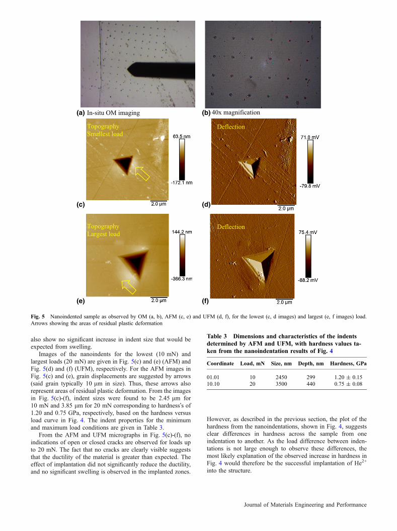
also show no significant increase in indent size that would beexpected from swelling.
Images of the nanoindents for the lowest (10 mN) andlargest loads (20 mN) are given in Fig. 5(c) and (e) (AFM) andFig. 5(d) and (f) (UFM), respectively. For the AFM images inFig. 5(c) and (e), grain displacements are suggested by arrows(said grain typically 10 lm in size). Thus, these arrows alsorepresent areas of residual plastic deformation. From the imagesin Fig. 5(c)-(f), indent sizes were found to be 2.45 lm for10 mN and 3.85 lm for 20 mN corresponding to hardness�s of1.20 and 0.75 GPa, respectively, based on the hardness versusload curve in Fig. 4. The indent properties for the minimumand maximum load conditions are given in Table 3.
From the AFM and UFM micrographs in Fig. 5(c)-(f), noindications of open or closed cracks are observed for loads upto 20 mN. The fact that no cracks are clearly visible suggeststhat the ductility of the material is greater than expected. Theeffect of implantation did not significantly reduce the ductility,and no significant swelling is observed in the implanted zones.
However, as described in the previous section, the plot of thehardness from the nanoindentations, shown in Fig. 4, suggestsclear differences in hardness across the sample from oneindentation to another. As the load difference between inden-tations is not large enough to observe these differences, themost likely explanation of the observed increase in hardness inFig. 4 would therefore be the successful implantation of He2+
into the structure.
(a) In-situ OM imaging (b) 40x magnification
(c) (d)
(e) (f)
Topography Largest load
Deflection
Topography Smallest load
Deflection
Fig. 5 Nanoindented sample as observed by OM (a, b), AFM (c, e) and UFM (d, f), for the lowest (c, d images) and largest (e, f images) load.Arrows showing the areas of residual plastic deformation
Table 3 Dimensions and characteristics of the indentsdetermined by AFM and UFM, with hardness values ta-ken from the nanoindentation results of Fig. 4
Coordinate Load, mN Size, nm Depth, nm Hardness, GPa
01.01 10 2450 299 1.20 ± 0.1510.10 20 3500 440 0.75 ± 0.08
Journal of Materials Engineering and Performance
4. Discussion
Over the last few decades, the study of the behavior of steelunder irradiation has been a key topic. Authors such as Randalland Renevier (Ref 34), Hosemann et al. (Ref 19) and Lupinacciet al. (Ref 35) have shown that steel materials behave wellduring irradiation from the grain to the atomistic level. Forexample, Hosemann did not detect any pileup during nanoin-dentation measurements of ferritic/martensitic stainless steelsgrades. Furthermore, in the early studies of Madden and Callen(Ref 7) on the microstructure of neutron (thermal and fast)irradiated 20Cr/25Ni/TiN austenitic stainless steel, similar incomposition to AGR clad, at 783 K showed that the steel wasfound to be relatively unaffected by irradiation at neutronfluence levels of 5.0 9 1024 m�2 (thermal) and2.5 9 1024 m�2 (fast) and helium bubble embrittlement wasunlikely under normal stresses. This has since been confirmedfor various steel types in several other more recent studies, forexample Fave et al. (Ref 36) who describe a similar responsefor ODS steels with lower He energy ions and shallowerpenetrations.
The nanoindentation results of section 3.3 show thatnanoscopic damage with only a small hardness increase(� 10%) occurs with He irradiation. Additionally, no cracksor significant swelling are observed for the applied loads byeither OM, AFM or UFM of indents.
This is in contrast to results by Lupinacci et al. (Ref 35) whohave reported in a recent study that 304 stainless steelundergoes significant hardness increases after irradiations of 1and 10 dpa, associated with plastic deformation in the irradi-ated area. However, this difference may be explained thus: first,damage calculations for the results reported here show that theirradiation damage levels are well below 1 dpa in accordancewith the observed hardness results, and secondly AGR steel hasa significantly different composition to 304 and is stabilizedakin to an ODS steel by the NbCN nanoinclusions.
Comparison of the results reported here may also be madewith those presented in recent studies by Kim et al. (Ref 37)and Chen et al. (Ref 38). Kim et al. (Ref 37) investigated themicrostructural evolution of NF709 (20Cr-25Ni-1.5MoNbTiN)under neutron irradiation. For 3 dpa, the hardness was observedto increase from about 3 (non-irradiated) to 5 GPa (irradiated).In this work, the damage is smaller and the variation ofhardness is consequently smaller. Chen et al. looked at theeffect of grain orientation on nanoindentation behavior of amodel austenitic alloy Fe-20Cr-25Ni (similar composition toAGR clad). They found that there is only a small effectof � 10% hardness difference by stressing along different grainorientations for a depth > 1 nm. This is similar to thatobserved here for grain displacements induced by He implan-tation.
In summary, the implantation of He2+ using an acceleratorhas been successfully achieved, mimicking the He concentra-tion and energy encountered in AGR cladding after irradiationduring current operation. Nanoindentation has been used toassess the effect of He irradiation on the mechanical propertiesof the AGR cladding steel. As described above, there are noobserved fundamental differences between implanted and non-implanted areas of the AGR steel confirming the work ofMadden and Callen (Ref 7).
Further development of the present preliminary study willinitially involve a detailed investigation of the influence of
helium on the mechanical properties of the implanted steel inthe He doped shallow layers. A low angle slope cut extendingacross the 10 lm implanted depth over approximately 100 lmshall be studied in using metallographic microscopes andscanning probe microscopes to explore in detail the mechanicalproperties along the He implanted depth and transitionsbetween implanted and original layers.
5. Conclusions
The production of a non-active sample simulating He gasbubble formation in AGR cladding material during reactoroperation has been successfully achieved. Such an approach isimportant because after in-reactor operation or alternativelyafter neutron irradiation AGR cladding is highly radioactiveand can only be analyzed in hot cells. The approach used herehas been instead to implant He2+ using an accelerator andperform sequential implantation with decreasing energy tomimic the buildup of He (e.g., 50 appm) in the irradiatedcladding material in layers of the order of 10 lm. Theimplanted sample was subsequently analyzed by SEM, nanoin-dentation, atom force and ultrasonic force microscopies. Asexpected the irradiated zones undergo nanoscopic damageswith only a small hardness increase (� 10%). Cracks were notobserved for any of the applied loads. Thus, for the tested AGRclad, there are no observed fundamental mechanical differencesbetween implanted and non-implanted areas of the AGR steelconfirming the integrity of the steel cladding under the appliedHe fluence conditions.
Open Access
This article is distributed under the terms of the CreativeCommons Attribution 4.0 International License (http://creativecommons.org/licenses/by/4.0/), which permits unrestricted use, distribution, and reproduction in any medium, provided you giveappropriate credit to the original author(s) and the source, provide alink to the Creative Commons license, and indicate if changes weremade.
References
1. B.J. Marsden and G.N. Hall, Graphite in Gas-Cooled Reactors,Reference Module in Materials Science and Materials Engineering,Current as of 28 October 2015 (2016)
2. L.R. Greenwood, D.W. Kneff, R.P. Skowronski, and F.M. Mann, AComparison of Measured and Calculated Helium Production in NickelUsing Newly Evaluated Neutron Cross Sections for 59Ni, J. Nucl.Mater., 1984, 123, p 1002–1010
3. V. Gopalakrishnan, R.V. Nandedkar, and S. Ganesan, Comparison ofCalculated Helium Production in Stainless Steel Due to NeutronIrradiation with Experiment, J. Nucl. Mater., 1996, 228, p 207–214
4. I.J. Ford, Intergranular Fracture of Fast Reactor Irradiated StainlessSteel, Acta Metall. Mater., 1992, 40, p 113–122
5. S.L. Mannan and P.V. Sivaprasad, Austenitic Stainless Steels for In-Core Applications of Fast Breeder Reactors, Reference Module inMaterials Science and Materials Engineering, Current as of 22 July2016 (2016)
6. G.R. Odette and G.E. Lucas, Embrittlement of Nuclear ReactorPressure Vessels, J. Nucl. Mater., 2001, 53, p 18–22
7. P.K. Madden and V.M. Callen, The Microstructure of NeutronIrradiated 20Cr/25Ni/TiN Austenitic Stainless Steel, J. Nucl. Mater.,1983, 113, p 46–57
Journal of Materials Engineering and Performance

8. G.R. Odette and G.E. Lucas, The Effects of Intermediate TemperatureIrradiation on the Mechanical Behavior of 300-Series AusteniticStainless Steels, J. Nucl. Mater., 1991, 179–181, p 572–576
9. N. Hashimoto, R.L. Klueh, and K. Shiba, Pros and Cons of Nickel -and Boron-Doping to Study Helium Effects in Ferritic/MartensiticSteels, J. Nucl. Mater., 2002, 307–311, p 222–228
10. R.L. Klueh, N. Hashimoto, M.A. Sokolov, P.J. Maziasz, and S.Jitsukawa, Mechanical Properties of Neutron-Irradiated Nickel-Con-taining Martensitic Steels: II. Review and Analysis of Helium-EffectsStudies, J. Nucl. Mater., 2006, 357, p 169–182
11. T. Yamamoto, G.R. Odette, H. Kishimoto, J.-W. Rensman, and P. Miao,On the Effects of Irradiation and Helium on the Yield Stress Changesand Hardening and Non-hardening Embrittlement of � 8Cr TemperedMartensitic Steels: Compilation and Analysis of Existing Data, J. Nucl.Mater., 2006, 356, p 27–49
12. M.A. Pouchon, A.J. Kropf, A. Froideval, C. Degueldre, and W.Hoffelner, An X-Ray Absorption Spectroscopy Study of an oxideDispersion Strengthened Steel, j. Nucl. Mater., 2007, 362, p 253–258
13. S. Cammelli, C. Degueldre, G. Kuri, and J. Bertsch, Study of a NeutronIrradiated Reactor Pressure Vessel Steel by X-Ray Absorption Spec-troscopy, Nucl. Instrum. Methods B, 2008, 266, p 4775–4781
14. C. Degueldre, G. Kuri, M. Martin, A. Froideval, S. Cammelli, A.Orlov, J. Bertsch, and M.A. Pouchon, Nuclear Material Investigationsby Advanced Analytical Techniques, Nucl. Instrum. Methods B, 2010,268, p 3364–3370
15. Y. Dai, J. Henry, Z. Tong, X. Averty, and B. Long, Neutron/protonIrradiation and He Effects on the Microstructure and MechanicalProperties of Ferritic/Martensitic Steels T91 and EM10, J. Nucl. Mater.,2011, 415, p 306–310
16. I. Villacampa, J.C. Chen, P. Spatig, H.P. Seifert, and F. Duval, HeliumBubble Evolution and Hardening in 316L by Post-ImplantationAnnealing, J. Nucl. Mater., 2018, 500, p 389–402
17. S. Jublot-Leclerc, M.-L. Lescoat, F. Fortuna, L. Legras, X. Li, and A.Gentils, TEM Study of the Nucleation of Bubbles Induced by HeImplantation in 316L Industrial Austenitic Stainless Steel, J. Nucl.Mater., 2015, 466, p 646–652
18. W.B. Liu, Y.Z. Ji, P.K. Tan, C. Zhang, C.H. He, and Z.G. Yang,Microstructure Evolution During Helium Irradiation and Post-irradia-tion Annealing in a Nanostructured Reduced Activation Steel, J. Nucl.Mater., 2016, 479, p 323–330
19. P. Hosemann, C. Vieh, R.R. Greco, S. Kabra, J.A. Valdez, M.J.Cappiello, and S.A. Maloy, Nanoindentation on Ion Irradiated Steels, J.Nucl. Mater., 2009, 389, p 239–247
20. P.P. Liu, F.R. Wan, and Q. Zhan, A Model to Evaluate the Nano-indentation Hardness of Ion-Irradiated Materials, Nucl. Instrum.Methods B, 2015, 342, p 13–18
21. Z.N. Ding, C.H. Zhang, Y.T. Yang, Y. Song, A. Kimura, and J. Jang,Hardening of ODS Ferritic Steel Under Irradiation with High-EnergyHeavy Ions, J. Nucl. Mater., 2017, 493, p 53–61
22. A.L. Marzoca, M.I. Luppo, and M. Zalazar, Identification of Precip-itates in Weldelements Performed in an ASTM A335 Gr P91 Steel bythe FCAW Process, Procedia Mater. Sci., 2015, 15, p 119–122
23. D. Newey, M.A. Wilkins, and H.M. Pollock, An Ultra-Low LoadPenetration Hardness Tester, J. Phys. E Sci. Instrum., 1982, 15, p 119–122
24. E.S. Berkovich, Three-Faceted Diamond Pyramid for StudyingMicrohardness by Indentation, Zavodskaya Laboratoria, 1950, 13, p345–347 ((in Russian))
25. N.A. Sakharova, J.V. Fernandes, J.M. Antunes, and M.C. Oliveira,Comparison Between Berkovich, Vickers and Conical IndentationTests: A Three-Dimensional Numerical Simulation Study, Int. J. SolidsStruct., 2009, 46, p 1095–1104
26. W.C. Oliver and G.M. Pharr, An Improved Technique for Determin-ing Hardness and Elastic-Modulus Using Load and DisplacementSensing Indentation Experiments, J. Mater. Res., 1992, 7, p 1564–1583
27. J.L. Bosse, P.D. Tovee, B.D. Huey, and O.V. Kolosov, PhysicalMechanisms of Megahertz Vibrations and Nonlinear Detection inUltrasonic Force and Related Microscopies, J. Appl. Phys., 2014, 115,p 144304
28. A. Briggs and O.V. Kolosov, Acoustic Microscopy, 2nd ed., OxfordUniversity Press, Oxford, 2009
29. R. Gr. Maev, Acoustic Microscopy: Fundamentals and Applications,Wiley, New York, 2008
30. F. Dinelli, S.K. Biswas, G.A.D. Briggs, and O.V. Kolosov, UltrasoundInduced Lubricity in Microscopic Contact, Appl. Phys. Lett., 1997, 71,p 1177–1179
31. J.F. Ziegler, M.D. Ziegler, and J.P. Biersack, SRIM—The Stopping andRange of Ions in Matter, Nucl. Instrum. Methods B, 2010, 268, p 1818–1823
32. J.P. Biersack and L.G. Haggmark, A Monte Carlo Computer Programfor the Transport of Energetic Ions in Amorphous Targets, Nucl.Instrum. Methods, 1980, 174, p 257–269
33. J.F. Ziegler, J.P. Biersack, and U. Littmark, The Stopping and Range ofIons in Matter, Pergamon, New York, 1985
34. N.X. Randall, N. Renevier, H. Michel, and P. Collignon, CorrelationBetween Processing Parameters and Technical Properties as a Functionof Substrate Polarization and Depth in a Nitrided 316L Stainless SteelUsing Nanoidentation and Scanning Force Microscopy, Vaccum, 1997,48, p 849–855
35. A. Lupinacci, K. Chen, Y. Li, M. Kunz, Z. Jiao, G.S. Was, M.D. Abed,A.M. Minor, and P. Hosemann, Characterisation of Ion Beam Irradiated304 Stainless Steel Utilising Nanoidentation and Laue Microdiffrac-tion, J. Nucl. Mater., 2015, 458, p 70–76
36. L. Fave, M.A. Pouchon, M. Dobeli, M. Schulte-Borchers, and A.Kimura, Helium Ion Irradiation Induced Swelling and Hardening inCommercial and Experimental ODS Steels, J. Nucl. Mater., 2014, 445,p 235–240
37. B.K. Kim, L. Tan, Y. Yang, X. Zhang, and M. Li, Micro StructuralEvolution of NF709 (20Cr-25Ni-1.5MoNbTiN) Under Neutron Irradi-ation, J. Nucl. Mater., 2015, 470, p 229–235
38. T. Chen, L. Tan, Z. Lu, and H. Xu, The Effect of Grain Orientation onNanoindentation Behavior of Model Austenitic Alloy Fe-20Cr-25Ni,Acta Mater., 2017, 138, p 83–91
Journal of Materials Engineering and Performance