Mechanical pressure gauges J - Lighting | Heating...216 Mechanical Pressure Gauges SIKA pressure...
69
J Mechanical pressure gauges J Bourdon tube pressure gauges J Differential pressure gauges J Diaphragm pressure gauges J capsule element pressure gauges DS_Mechanical_pressure_gauges 08/2015 Contains products with:
Transcript of Mechanical pressure gauges J - Lighting | Heating...216 Mechanical Pressure Gauges SIKA pressure...

JMechanical pressure gauges
J Bourdon tube pressure gauges
J Differential pressure gauges
J Diaphragm pressure gauges
J capsule element pressure gauges
DS_Mechanical_pressure_gauges 08/2015
Contains products with:
Natalie Lundie
HP Stamp

216
Mechanical Pressure Gauges
SIKA pressure gauges are quality measuring instruments for use in industrial applications. They are fitted with stainless steel
cases as standard and comply with the EN 837-1 until EN 837-3 European standards.
SIKA offers various models based on three different measuring elements: bourdon tubes, diaphragms and capsule elements. All
three types operate on the same principle: elastic deformation of the measuring element under the influence of pressure. This
motion is coupled to a pointer mechanism. The appropriate type (bourdon tube, diaphragm or capsule element) for a particular
application depends on the application area, necessary display range and installation location.
Bourdon tube pressure gauges
Bourdon tube pressure gauges are the most common type in
many areas and are used to measure medium to high pressures.
They cover measuring spans from 600 mbar to 4000 bar.
The measuring element is a curved tube with a circular, spiral
or coiled shape, commonly called a bourdon tube. This tube
moves outward when the pressure inside the tube is higher
than the external pressure, and inward when the internal
pressure is lower. This motion is proportional to the pressure to
be measured, and it is coupled to the pointer mechanism.
General information
The provisions of Part 2 of the EN 837 standard should generally
be observed when selecting pressure gauges. We offer a variety
of standard and special versions of pressure gauges, as well
as matching accessories. On request, we can fit our gauges
with electrical limit switches, which are described in a separate
section limit switches. Please don‘t hesitate to contact us if you
have any questions.

217
Capsule element pressure gauge
Capsule element pressure gauges are used to measure air
and dry gases at low pressures. They cover measuring spans
from 2.5 mbar to 600 mbar. The measuring element consists of
two metal diaphragms soldered together to form a cylindrical
bellows chamber. This capsule element expands when the
pressure inside the element is higher than the external
pressure, and it contracts when the internal pressure is lower.
This motion is proportional to the pressure to be measured, and
it is coupled to the pointer mechanism.
Diaphragm pressure gauges
Diaphragm pressure gauges are used to measure gases and
liquids. They cover measuring spans from 10 mbar to 40 bar.
The measuring element consists of one circular diaphragm
clamped between a pair of flanges. The positive or negative
pressure acting on these diaphragms causes deformation of
the measuring element. The magnitude of the deformation is
proportional to the pressure to be measured, and it is coupled
to the pointer mechanism.

218
Case type
The stainless steel case is available in two versions: with a
bayonet ring (type MRE) or with a crimped-on ring (type MRE-g).
Case ventilation is provided by a pressure equalisation insert.
Display ranges
DIN display ranges from -1...0 bar to 0...1000 bar are available
(max. 600 bar with brass connection or 1000 bar with stainless
steel connection). Gauges with special ranges can be provided
on request.
Degree of protection according to EN 60529
IP54 (IP65 for filled case with closed pressure equalisation
insert). Types other than IP65 available on request.
Dial
Aluminium, white with black scale markings.
Pointer: Aluminium, black
Window
Instrument glass for types with brass connection thread,
laminated safety glass for type MRE with stainless steel connection,
polycarbonate for type MRE-g with stainless steel connection.
Pointer movement
Brass & German silver; stainless steel for gauges with stainless
steel connection.
Connection threads and materials
Standard pressure gauges have a brass connection thread
and bronze Bourdon tube. Version with connection thread and
Bourdon tube made from stainless steel is optionally available.
Temperature range
• Storage temperature
-40...70 °C (-20...70 °C with filled case)
• Ambient operating temperature
-40...60 °C (-20...60 °C with filled case)
• Media temperature
Gauges with brass connection 60 °C max.
Gauges with stainless steel connection 200 °C max.
(100 °C max. with filled case)
Ambient temperature sensivity
The pressure gauges are calibrated at a reference temperature
of 20 °C. At other operating temperatures the maximum
indication error is ±0.4 % of full scale value per 10 °C difference
in accordance with EN 837-1.
Options
• Safety version with baffle compliant with EN 873-1 S3 (only with bayonet ring case)
• Throttle screw in input channel
• Versions for higher media temperatures
• With glycerine filled case
• Adjustable pointer, aluminium (only unfilled)
• Aluminium adjustable pointer (only with unfilled case)
• Customer-specific special scales available with large order
quantities
SIKA quality industrial-grade pressure gauges with 63 mm
stainless steel cases are suitable for measuring the pressure
of gaseous or liquid media, but not for highly viscous or
crystallizing media.
• Pressure gauges compliant with EN 837-1
• Stainless steel case with bayonet ring or crimped-on ring
• Brass or stainless steel threaded connection
• Connection at bottom or back, G¼ B
• EN 837-1 accuracy class 1.6,
class 2.5 (for display ranges 0...600 bar and 0...1000 bar)
• GL type approval certificate available
Bourdon tube pressure gauges, industrial version
Type MRE and MRE-g, nominal size 63 mm
Type Mre-g
Maximum pressure load
Static load 75 % of full-scale value
Dynamic load 65 % of full-scale value
Overload Full scale-value
219
* Data applies to versions without mounting flange
* Versions available on request, but not recommended
by EN 837-1.
** Front flange with oval holes and separate trim ring, recommended panel cut out Ø 67 ± 0.3 mm
Types and dimensions - bayonet ring case
With front flange**Bottom connection*, lower back connection or central back connection
With rear flangeBottom connection, lower back connection* or central back connection*
Without mounting flangeBottom connection, lower back connection or central back connection
Dimensions [mm]
NS D D1 D2 a a1 b b1 b2 b3 c c1 c2 c3 d1 d2
63 64 62 66 10 13 33 37 36 40 5 2 13 13 75 85
Dimensions [mm] Weight [kg] (approx.)*NS d3 e G G1 g g1 h h1 s s2 s3 SW unfilled filled
63 3.6 18 G¼ B
M12 x 1.5
¼ NPT 59 59 54 54 5 2 5.5 14 0.18 0.25
220
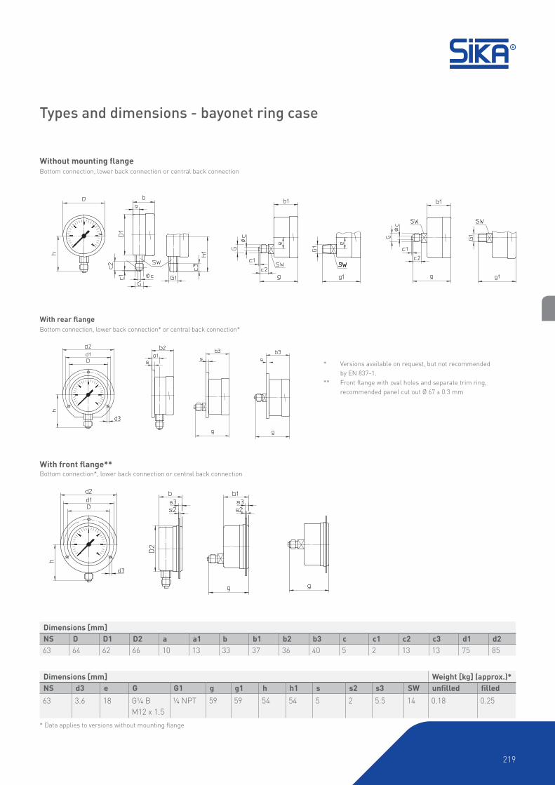
* Data applies to versions without mounting flange
Without mounting flangeBottom connection, lower back connection or central back connection
With u-clamp***Lower back connection or central back connection
With front flange**Lower back connection or central back connection
With rear flangeBottom connection, lower back connection* or central back* connection
* Versions available on request, but not recommended by EN 837-1
** Recommended panel cut out Ø 67 ± 0.3 mm
*** Recommended panel cut out Ø 64 ± 0.3 mm
Types and dimensions – crimped-on ring case
Dimensions [mm]
NS D D1 D2 a a1 b b1 b2 b3 c c1 c2 c3 d1 d2
63 67 62 64 10 13 33 37 36 40 5 2 13 13 75 85
Dimensions [mm] Weight [kg] (approx.)*NS d3 e G G1 g g1 h±1 h1±1 s s1 s3 s4 SW unfilled filled
63 3.6 18 G¼ B
M12 x 1.5
¼ NPT 60 60 54 54 5 1 9.5 8.5 14 0.18 0.25
221
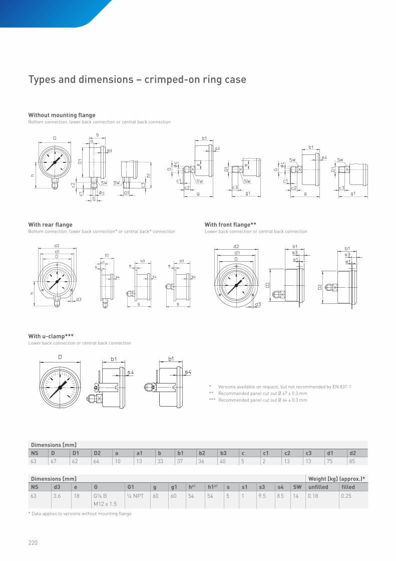
Order code
Order example MRE 1 1 1 315 0 0 0
Bourdon tube pressure gauges, industrial version
Bayonet ring caseCrimped-on ring case
MREMREG
Nominal size
63 mm 1
Connection thread
G¼ B bottomG¼ B lower back connectionG¼ B central back connection¼ NPT bottom¼ NPT lower back connection¼ NPT central back connectionM12 x 1.5 bottomM12 x 1.5 lower back connectionM12 x 1.5 central back connection
125MNS346
Connection material
BrassStainless steel
13
Display ranges
-1...0 bar-1...0.6 bar-1...1.5 bar-1...3 bar-1...5 bar
315505515525535
-1...9 bar-1...15 bar0...0.6 bar0...1 bar0...1.6 bar
545555015025035
0...2.5 bar0...4 bar0...6 bar0...10 bar0...16 bar
045055065075085
0...25 bar0...40 bar0...60 bar0...100 bar0...160 bar
095105115125135
0...250 bar0...400 bar0...600 bar0...1000 bar only with crimped-on ring case (connection material stainless steel)
145155165175
Mounting flangeNoneRear flangeFront flangeU-clamp only with crimped-on ring case
0123
Option
None 0
Filled case
Unfilled caseFilled case (glycerine)
0G

222
Case type
Available only with type MRE-g crimped-on ring case. Case
ventilation is provided by a pressure equalisation insert.
Display ranges
DIN display ranges from -1...0 bar to 0...1000 bar available
(max. 600 bar with brass connection block; max. 1000 bar with
stainless steel connection block). Gauges with special ranges
can be provided on request.
Degree of protection according to EN 60529
IP65 with closed pressure equalisation insert.
Dial
Aluminium, white with black scale markings.
Pointer: Aluminium, black
Window
Instrument glass; gauges with stainless steel connection have
laminated safety glass.
Pointer movement
Brass & German silver; stainless steel for gauges with stainless
steel connection.
Connection threads and materials
Standard pressure gauges have brass connection threads and
bronze Bourdon tubes. A version with connection thread and
Bourdon tube made from stainless steel is optionally available.
Temperature range
• Storage temperature
-40 to 70 °C (-20 to 70 °C with filled case)
• Ambient operating temperature
-40 to 60 °C (-20 to 60 °C with filled case)
• Media temperature
Gauges with brass connection 60 °C max.
Gauges with stainless steel connection 200 °C max.
(100 °C max. with filled case)
Ambient temperature sensitivity
The pressure gauges are calibrated at a reference temperature
of 20 °C. At other operating temperatures the maximum
indication error is ±0.4 % of full scale value per 10 °C difference
in accordance with EN 837-1.
Options
• Throttle screw in input channel
• Versions for higher media temperatures
• With glycerine filled case
• Customer-specific special scales available with large
order quantities
SIKA quality industrial-grade pressure gauges with
80 mm stainless steel cases are suitable for measuring the
pressure of gaseous or liquid media, but not for highly viscous
or crystallizing media.
• Pressure gauges compliant with EN 837-1
• Stainless steel case with crimped-on ring
• Brass or stainless steel threaded connection
• Connection at bottom or central back, G½ B
• EN 837-1 accuracy class 1.0, class 1.6
(for display range 0...600 or 0...1000 bar)
• GL type approval certificate available
Type MRE-g, nominal size 80 mm
Type Mre-g
Maximum pressure load
Static load 75 % of full scale value
Dynamic load 65 % of full scale value
Overload Max. full scale value
223
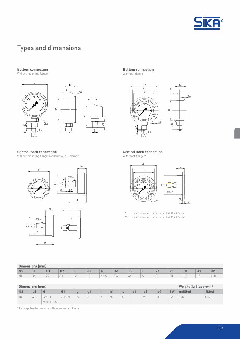
Bottom connectionWith rear flange
Bottom connectionWithout mounting flange
Central back connectionWith front flange**
Central back connection Without mounting flange (available with u-clamp)*
* Data applies to versions without mounting flange
* Recommended panel cut out Ø 81 ± 0.5 mm
** Recommended panel cut out Ø 84 ± 0.5 mm
Types and dimensions
Dimensions [mm]
NS D D1 D2 a a1 b b1 b2 c c1 c2 c3 d1 d2
80 86 79 81 16 19 41.5 36 44 6 3 20 19 95 110
Dimensions [mm] Weight [kg] (approx.)*NS d3 G G1 g g1 h h1 s s1 s3 s4 SW unfilled filled
80 4.8 G½ B
M20 x 1.5
½ NPT 74 73 76 75 5 1 9 8 22 0.34 0.50
224
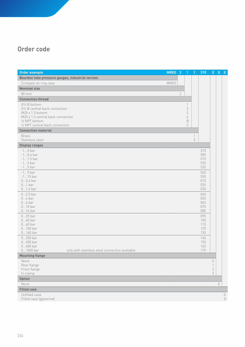
Order code
Order example MREG 2 1 1 315 0 0 0
Bourdon tube pressure gauges, industrial version
Crimped-on ring case MREG
Nominal size
80 mm 2
Connection thread
G½ B bottomG½ B central back connectionM20 x 1.5 bottomM20 x 1.5 central back connection½ NPT bottom½ NPT central back connection
1234BC
Connection material
BrassStainless steel
13
Display ranges
-1...0 bar-1...0.6 bar-1...1.5 bar-1...3 bar-1...5 bar
315505515525535
-1...9 bar-1...15 bar0...0.6 bar0...1 bar0...1.6 bar
545555015025035
0...2.5 bar0...4 bar0...6 bar0...10 bar0...16 bar
045055065075085
0...25 bar0...40 bar0...60 bar0...100 bar0...160 bar
095105115125135
0...250 bar0...400 bar0...600 bar0...1000 bar only with stainless steel connection available
145155165175
Mounting flangeNoneRear flangeFront flangeU-clamp
0123
Option
None 0
Filled case
Unfilled caseFilled case (glycerine)
0G

-225-
225
226
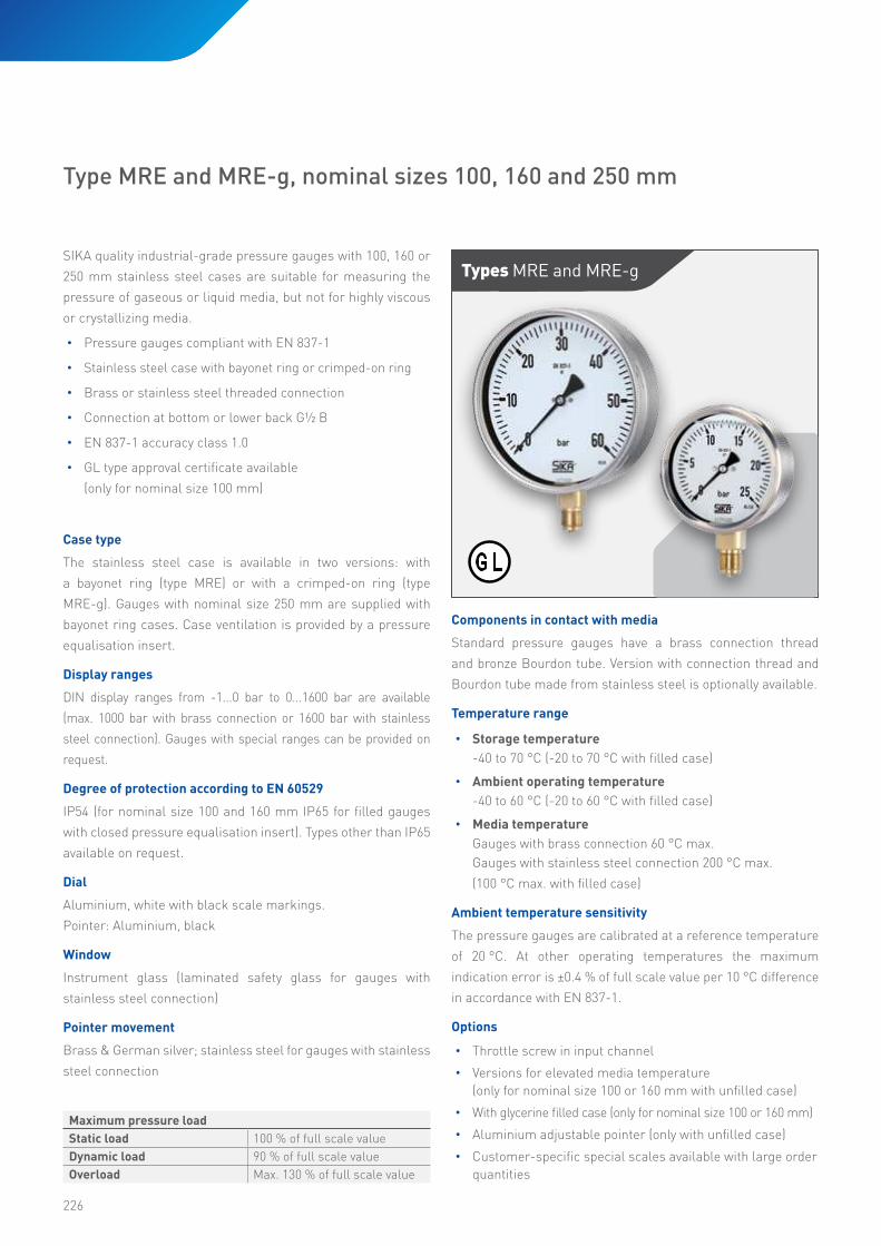
SIKA quality industrial-grade pressure gauges with 100, 160 or
250 mm stainless steel cases are suitable for measuring the
pressure of gaseous or liquid media, but not for highly viscous
or crystallizing media.
• Pressure gauges compliant with EN 837-1
• Stainless steel case with bayonet ring or crimped-on ring
• Brass or stainless steel threaded connection
• Connection at bottom or lower back G½ B
• EN 837-1 accuracy class 1.0
• GL type approval certificate available
(only for nominal size 100 mm)
Types Mre and Mre-g
Type MRE and MRE-g, nominal sizes 100, 160 and 250 mm
Case type
The stainless steel case is available in two versions: with
a bayonet ring (type MRE) or with a crimped-on ring (type
MRE-g). Gauges with nominal size 250 mm are supplied with
bayonet ring cases. Case ventilation is provided by a pressure
equalisation insert.
Display ranges
DIN display ranges from -1...0 bar to 0...1600 bar are available
(max. 1000 bar with brass connection or 1600 bar with stainless
steel connection). Gauges with special ranges can be provided on
request.
Degree of protection according to EN 60529
IP54 (for nominal size 100 and 160 mm IP65 for filled gauges
with closed pressure equalisation insert). Types other than IP65
available on request.
Dial
Aluminium, white with black scale markings.
Pointer: Aluminium, black
Window
Instrument glass (laminated safety glass for gauges with
stainless steel connection)
Pointer movement
Brass & German silver; stainless steel for gauges with stainless
steel connection
Components in contact with media
Standard pressure gauges have a brass connection thread
and bronze Bourdon tube. Version with connection thread and
Bourdon tube made from stainless steel is optionally available.
Temperature range
• Storage temperature
-40 to 70 °C (-20 to 70 °C with filled case)
• Ambient operating temperature
-40 to 60 °C (-20 to 60 °C with filled case)
• Media temperature
Gauges with brass connection 60 °C max.
Gauges with stainless steel connection 200 °C max.
(100 °C max. with filled case)
Ambient temperature sensitivity
The pressure gauges are calibrated at a reference temperature
of 20 °C. At other operating temperatures the maximum
indication error is ±0.4 % of full scale value per 10 °C difference
in accordance with EN 837-1.
Options
• Throttle screw in input channel
• Versions for elevated media temperature
(only for nominal size 100 or 160 mm with unfilled case)
• With glycerine filled case (only for nominal size 100 or 160 mm)
• Aluminium adjustable pointer (only with unfilled case)
• Customer-specific special scales available with large order quantities
Maximum pressure load
Static load 100 % of full scale value
Dynamic load 90 % of full scale value
Overload Max. 130 % of full scale value

227
Without mounting flangeBottom connection or lower back connection
With rear flange***Bottom connection** or lower back connection*
With front flangeBottom connection* or lower back connection****
* Version available on request, but not recommended by EN 837-1.
** Nominal size 100 rear flange optionally available with oval holes compliant with EN 837-1.*** With three lugs for nominal size 250.
**** Recommended panel cut out Ø 104 ± 0.5 mm for NS 100; Ø 164 ± 0.5 mm for NS 160; Ø 254 ± 0.5 mm for NS 250.
***** Welded lugs and separate fixing flange at front.
Types and dimensions – bayonet ring case
* Data applies to versions without mounting flange
Dimensions [mm] Weight [kg] (approx.)*NS d3 d5 G G1 e g g1 h±1 h1±1 s s1 s2 s3 s5 SW SW1 unfilled filled
100 4.8 M4 G½ B
M20 x 1.5
½ NPT 30 97 96 87 84 6 1 2 5.5 7 22 17 0.60 0.95
160 5.8 M5 G½ B
M20 x 1.5
½ NPT 30 92.5 91.5 115 114 6 1.5 2.5 6 8 22 17 1.10 1.95
250 5.8 G½ B
M20 x 1.5
½ NPT 52 97 96 165 164 6 - 2 8.5 - 22 17 2.10
Dimensions [mm]
NS D D1 D2 a a1 b b1 b2 b3 c c1 c2 c3 d1 d2
100 101 99 103 20 23.5 55 55 58.5 58.5 6 3 20 19 116 132
160 161 159 163 15 18 50 55 53 58 6 3 20 19 178 196
250 251 249 15.5 17.5 58 58 60 60 6 3 20 19 270 285
Einbautafel
***** *****
Panel
228
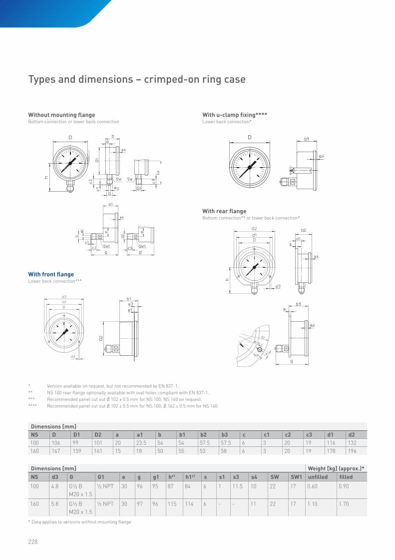
* Version available on request, but not recommended by EN 837-1.
** NS 100 rear flange optionally available with oval holes compliant with EN 837-1.*** Recommended panel cut out Ø 102 ± 0.5 mm for NS 100; NS 160 on request.
**** Recommended panel cut out Ø 102 ± 0.5 mm for NS 100; Ø 162 ± 0.5 mm for NS 160.
* Data applies to versions without mounting flange
Without mounting flangeBottom connection or lower back connection
With front flangeLower back connection***
With rear flangeBottom connection** or lower back connection*
With u-clamp fixing****Lower back connection*
Types and dimensions – crimped-on ring case
Dimensions [mm] Weight [kg] (approx.)*NS d3 G G1 e g g1 h±1 h1±1 s s1 s3 s4 SW SW1 unfilled filled
100 4.8 G½ B
M20 x 1.5
½ NPT 30 96 95 87 84 6 1 11.5 10 22 17 0.60 0.90
160 5.8 G½ B
M20 x 1.5
½ NPT 30 97 96 115 114 6 - - 11 22 17 1.10 1.70
Dimensions [mm]
NS D D1 D2 a a1 b b1 b2 b3 c c1 c2 c3 d1 d2
100 106 99 101 20 23.5 54 54 57.5 57.5 6 3 20 19 116 132
160 167 159 161 15 18 50 55 53 58 6 3 20 19 178 196
229
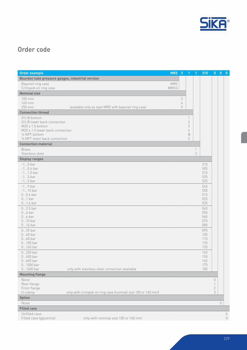
Order code
Order example MRE 3 1 1 315 0 0 0
Bourdon tube pressure gauges, industrial version
Bayonet ring caseCrimped-on ring case
MREMREG
Nominal size
100 mm160 mm250 mm available only as type MRE with bayonet ring case
345
Connection thread
G½ B bottomG½ B lower back connectionM20 x 1.5 bottomM20 x 1.5 lower back connection½ NPT bottom½ NPT lower back connection
1234BC
Connection material
BrassStainless steel
13
Display ranges
-1...0 bar-1...0.6 bar-1...1.5 bar-1...3 bar-1...5 bar
315505515525535
-1...9 bar-1...15 bar0...0.6 bar0...1 bar0...1.6 bar
545555015025035
0...2.5 bar0...4 bar0...6 bar0...10 bar0...16 bar
045055065075085
0...25 bar0...40 bar0...60 bar0...100 bar0...160 bar
095105115125135
0...250 bar0...400 bar0...600 bar0...1000 bar0...1600 bar only with stainless steel connection available
145155165175185
Mounting flangeNoneRear flangeFront flangeU-clamp only with crimped-on ring case (nominal size 100 or 160 mm)
0123
Option
None 0
Filled case
Unfilled caseFilled case (glycerine) only with nominal size 100 or 160 mm
0G
230
Case type
The stainless steel case has a bayonet ring and is designed to
conform to safety requirements similar to EN 837-1 S3. The
gauges have a sturdy baffle between the dial plate and the
Bourdon tube and connection block. The entire back cover is
designed to blow out.
Display ranges
Available with DIN display ranges from -1...0 bar to 0...1600 bar
or 0...1000 bar (only with brass connection). Special ranges can
be provided on request.
Degree of protection according to EN 60529
IP54 (IP65 with filled case)
Dial
Aluminium, white with black scale markings.
Pointer: Aluminium, black
Window
Laminated safety glass
Pointer movement
Brass & German silver; stainless steel for gauges with stainless
steel connection.
Connection threads and materials
Standard pressure gauges have a brass connection block and
bronze Bourdon tube. A version with the connection block and
Bourdon tube made from stainless steel is optionally available.
Temperature range
• Storage temperature
-40 to 70 °C (-20 to 70 °C with filled case)
• Ambient operating temperature
-40 to 60 °C (-20 to 60 °C with filled case)
• Media temperature
Gauges with brass connection 60 °C max.
Gauges with stainless steel connection 200 °C max.
(100 °C max. with filled case)
Ambient temperature sensitivity
The pressure gauges are calibrated at a reference temperature
of 20 °C. At other operating temperatures the maximum
indication error is ±0.4 % of full scale per 10 °C difference in
accordance with EN 837-1.
Options
• Throttle screw in inlet channel
• With glycerine filled case
• Aluminium adjustable pointer (only with unfilled case)
• Customer-specific special scales are available with large
order quantities
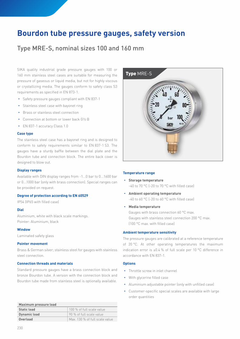
Type Mre-sSIKA quality industrial grade pressure gauges with 100 or
160 mm stainless steel cases are suitable for measuring the
pressure of gaseous or liquid media, but not for highly viscous
or crystallizing media. The gauges conform to safety class S3
requirements as specified in EN 873-1.
• Safety pressure gauges compliant with EN 837-1
• Stainless steel case with bayonet ring
• Brass or stainless steel connection
• Connection at bottom or lower back G½ B
• EN 837-1 accuracy Class 1.0
Bourdon tube pressure gauges, safety version
Type MRE-S, nominal sizes 100 and 160 mm
Maximum pressure load
Static load 100 % of full scale value
Dynamic load 90 % of full scale value
Overload Max. 130 % of full scale value
231
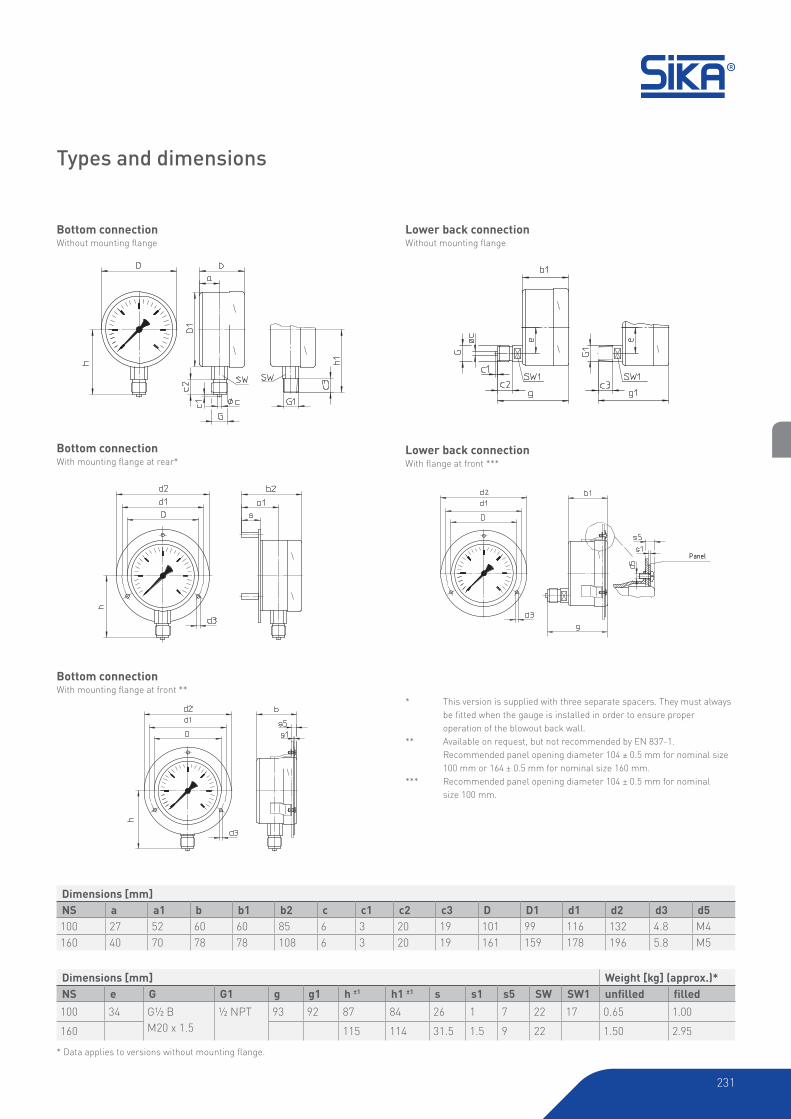
Lower back connectionWithout mounting flange
Bottom connection Without mounting flange
Lower back connectionWith flange at front ***
Bottom connectionWith mounting flange at rear*
Bottom connection With mounting flange at front **
* This version is supplied with three separate spacers. They must always
be fitted when the gauge is installed in order to ensure proper operation of the blowout back wall.
** Available on request, but not recommended by EN 837-1.
Recommended panel opening diameter 104 ± 0.5 mm for nominal size
100 mm or 164 ± 0.5 mm for nominal size 160 mm.
*** Recommended panel opening diameter 104 ± 0.5 mm for nominal
size 100 mm.
* Data applies to versions without mounting flange.
Types and dimensions
Dimensions [mm]
NS a a1 b b1 b2 c c1 c2 c3 D D1 d1 d2 d3 d5
100 27 52 60 60 85 6 3 20 19 101 99 116 132 4.8 M4
160 40 70 78 78 108 6 3 20 19 161 159 178 196 5.8 M5
Dimensions [mm] Weight [kg] (approx.)*NS e G G1 g g1 h ±1 h1 ±1 s s1 s5 SW SW1 unfilled filled
100 34 G½ B
M20 x 1.5
½ NPT 93 92 87 84 26 1 7 22 17 0.65 1.00
160 115 114 31.5 1.5 9 22 1.50 2.95
Panel

232
Order code
Order example MRES 3 1 1 315 0 0 0
Bourdon tube pressure gauges, safety version
Bayonet ring case MRES
Nominal size
100 mm160 mm
34
Connection thread
G½ B bottomG½ B lower backM20 x 1.5 bottomM20 x 1.5 lower back½ NPT bottom½ NPT lower back
1234BC
Connection material
BrassStainless steel
13
Display ranges
-1...0 bar-1...0.6 bar-1...1.5 bar-1...3 bar-1...5 bar
315505515525535
-1...9 bar-1...15 bar0...0.6 bar0...1 bar0...1.6 bar
545555015025035
0...2.5 bar0...4 bar0...6 bar0...10 bar0...16 bar
045055065075085
0...25 bar0...40 bar0...60 bar0...100 bar0...160 bar
095105115125135
0...250 bar0...400 bar0...600 bar0...1000 bar0...1600 bar only with stainless steel connection available
145155165175185
Mounting flangeNoneRear flangeFront flange
012
Option
None 0
Filled case
Unfilled caseFilled case (glycerine)
0G

-233-
233

234
Case type
The stainless steel case has a bayonet ring and is designed to
conform to safety requirements similar to EN 837-1 S3. The
gauges have a sturdy baffle between the dial plate and the
Bourdon tube and connection block. The entire back cover is
designed to blow out.
Display ranges
DIN display ranges 0...2500 bar and 0...4000 bar available.
Degree of protection according toEN 60529
IP54 (IP65 with filled case)
Dial
Aluminium, white with black scale markings.
Pointer: Aluminium, black
Window
Laminated safety glass
Pointer movement
Stainless steel
Components in contact with media
The connection thread is made from stainless steel, and the
spiral Bourdon tube is made from either stainless steel or
nickel-iron alloy, depending on the display range.
Temperature range
• Storage temperature
-40 to 70 °C (-20 to 70 °C with filled case)
• Ambient operating temperature
-40 to 60 °C (-20 to 60 °C with filled case)
• Media temperature
200 °C max. (100 °C max. with filled case)
Ambient temperature sensitivity
The pressure gauges are calibrated at a reference temperature
of 20 °C. At other operating temperatures the maximum
indication error is ±0.4 % of full scale value per 10 °C difference
in accordance with EN 837-1.
Options
• Other high-pressure threads
• Display range 0...3000 bar; others available on request
• With glycerine filled case
• Aluminium adjustable pointer (only with unfilled case)
• Customer-specific special scales available with large order
quantities
Type Mre-s-hDSIKA quality high-pressure gauges with 100 or 160 mm stainless
steel cases are suitable for measuring pressures up to 4000 bar
in hydraulic systems.
• Safety pressure gauges compliant with EN 837-1 S3
• Stainless steel case with bayonet ring
• High-pressure process connection with M16 x 1.5 female
thread and sealing cone for ¼“ tube
• Connection at bottom
• EN 837-1 accuracy class 1.0
Maximum pressure load
Static load 100 % of full scale value
Dynamic load 65 % of full scale value
Overload Max. full scale value
Bourdon tube pressure gauges, high-pressure version
Type MRE-S-HD, nominal sizes 100 and 160 mm

235
Bottom connectionWithout mounting flange, NS 100
Bottom connection Without mounting flange*, NS 160 with wall bracket
Bottom connectionWith front flange***
Bottom connectionWith rear flange**
* Data applies to versions without mounting flange
* An aluminium wall bracket with black finish and 60 mm protrusion is included in the price for this version (scale range 0...4000 bar).
** This version comes with three separate standoffs. They must always be fitted when the gauge is installed in order to ensure proper functioning of the blow out
back wall spacers.
*** Version with three fixing lugs welded to the case and a separate trim ring with three holes.
Types and dimensions
Dimensions [mm]
NS D d1 d2 d3 d4 d5 d6 d7 d8 a a1 b b1
100 101 116 132 4.8 M4 2.5 4.3 M16 x 1.5 HD - 27 52 60 90
160 161 178 196 5.8 M5 2.5 4.3 M16 x 1.5 HD 26 34 64 78 108
Dimensions [mm] Weight [kg] (approx.)*NS h ±1 o s s1 s2 t t1 u u1 SW unfilled filled
100 71 - 1 26 7 9.5 11 - - 22 0.65 1.00
160 139 63 1.5 32 8 9.5 11 65 56 22 2.00 3.10

236
Order code
Order example MRESHD 3 H 3 195 0 0 0
Bourdon tube safety pressure gauges, high-pressure version
Bayonet ring case MRESHD
Nominal size
100 mm160 mm
34
Connection thread
High-pressure bottom connection (M16x1.5 female thread and sealing cone for ¼“ tube) H
Connection material
Stainless steel 3
Display ranges
0...2500 bar0...4000 bar
195205
Mounting flangeNoneRear flangeFront flange
012
Option
None 0
Filled case
Unfilled caseFilled case (glycerine)
0G

-237-
237

238
Case type
The stainless steel case has a bayonet ring. Gauges with 100
and 160 mm nominal size are optionally available with filled case
(glycerine).
Display ranges
DIN scale ranges from -1...0 bar to 0...600 bar or 0...1,600 bar (with
stainless steel connection) are available. Filled case versions
are available with scale ranges of 1...1.5 bar. Special ranges can
be provided on request. See order code for detailed information.
Degree of protection according to EN 60529
IP54 (IP65 with filled case)
Dial
Aluminium, white; black scale markings
Pointer: knive edge pointer for precise reading
Window
Instrument glass; laminated safety glass for gauges with
stainless steel connection
Pointer movement
Brass & German silver, low-friction.
Connection threads and materials
The connection block is made from brass; the Bourdon tube is
made from bronze or another copper alloy. Bourdon tubes of
gauges with stainless steel connection are made from stainless
steel; Bourdon tubes for scale ranges ≥1000 bar are made from
nickel-steel alloys.
Temperature range
• Storage temperature
-40 to 70 °C (-20 to 70 °C with filled case)
• Ambient operating temperature
-40 to 60 °C (-20 to 60 °C with filled case)
• Media temperature
Gauges with brass connection 60 °C max.
Gauges with stainless steel connection 200 °C max.
(100 °C max. with filled case)
Ambient temperature sensitivity
The pressure gauges are calibrated at a reference temperature
of 20 °C. At other operating temperatures the maximum
indication error is ±0.4 % of full scale per 10 °C difference in
accordance with EN 837-1.
Options
• Adjustment screw for zero point correction (with unfilled
case versions, only for NS 160 and 250 mm)
• Throttle screw in inlet channel
• With glycerine filled case
Type MFeSIKA quality precision pressure gauges with 100, 160 or 250 mm
stainless steel cases are suitable for the precise measurement
of the pressure of gaseous or liquid media, but not for highly
viscous or crystallizing media. These gauges are used in
precision equipment, in laboratories and for checking plant
pressure gauges.
• Precision pressure gauges compliant with EN 837-1
• Stainless steel case with bayonet ring
• Brass or stainless steel connection
• Connection at bottom or lower back G½ B
• EN 837-1 accuracy class 0.6
Bourdon tube pressure gauges, precision version
Type MFE, nominal sizes 100, 160 and 250 mm
Maximum pressure load
Static load Full scale value
Dynamic load 90 % of full scale value
Overload Max. 130 % of full scale value

239
Types and dimensions
* Nominal size 250, with lugs
** Unfilled version, with fixed front ring, with oval holes and separate trim ring for nominal size 160 Filled version, with lugs welded onto case and separate front ring
*** Available on request, but not recommended by EN 837-1.
**** NS 100 optionally available with oval holes compliant with EN 837-1.
***** Recommended panel opening: Ø 104 ± 0.5 mm for NS 100; Ø 164 ± 0.5 mm for NS 160; Ø 254 ± 0.5 mm for NS 250
* Data applies to versions without mounting flange
With front mounting flange Lower back connection**
With front mounting flangeConnection at bottom**
********
unfilled unfilledfilled filled
Without mounting flangeLower back connection
Without mounting flangeBottom connection
With u-clampConnection at lower back
With rear mounting flange*Bottom or lower back connection***
*******
Dimensions [mm]
NS a a1 b b1 c c1 c2 c3 D D1 d1 d2 d3 e g g1
100 20 23.5 55 58.5 6 3 20 19 101 99 116 132 4.8 30 97 96
160 15.5 19 51 54 6 3 20 19 161 167 178 196 5.8 52 92.5 91.5
250 15.5 17.5 58 60 6 3 20 19 251 - 270 285 5.8 52 97 96
Dimensions [mm] Weight [kg] (approx.)*NS G G1 h ±1 h1 ±1 s s1 s2 s3 SW SW1 unfilled filled100 G½ B
M20 x 1.5
½ NPT 87 84 2 6 5.5 - 22 17 0.60 0.95
160 115 114 2.5 6 6 1.5 22 17 1.10 1.95
250 165 164 2 2 7 2 22 17 2.10 -
240
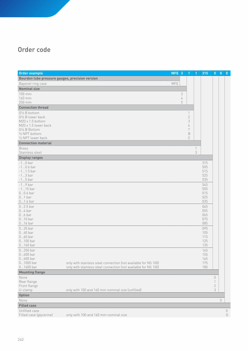
Order example MFE 3 1 1 315 0 0 0
Bourdon tube pressure gauges, precision version
Bayonet ring case MFE
Nominal size
100 mm160 mm250 mm
345
Connection thread
G½ B bottomG½ B lower backM20 x 1.5 bottomM20 x 1.5 lower backG¼ B Bottom½ NPT bottom½ NPT lower back
12347BC
Connection material
BrassStainless steel
13
Display ranges
-1...0 bar-1...0.6 bar-1...1.5 bar-1...3 bar-1...5 bar
315505515525535
-1...9 bar-1...15 bar0...0.6 bar0...1 bar0...1.6 bar
545555015025035
0...2.5 bar0...4 bar0...6 bar0...10 bar0...16 bar
045055065075085
0...25 bar0...40 bar0...60 bar0...100 bar0...160 bar
095105115125135
0...250 bar0...400 bar0...600 bar0...1000 bar only with stainless steel connection (not available for NS 100)0...1600 bar only with stainless steel connection (not available for NS 100)
145155165175185
Mounting flangeNoneRear flangeFront flangeU-clamp only with 100 and 160 mm nominal size (unfilled)
0123
Option
None 0
Filled case
Unfilled caseFilled case (glycerine) only with 100 and 160 mm nominal size
0G
Order code

-241-
241
242
Ambient temperature sensitivity
The pressure gauges are calibrated at a reference temperature
of 20 °C. At other operating temperatures the maximum
indication error is ±0.4 % of full scale value per 10 °C difference
in accordance with EN 837-1.
Case type
Available only with type MRE-g crimped-on ring case. Case
ventilation is provided by a pressure equalisation insert.
Display ranges
DIN display ranges from -1…0 bar to 0…600 bar available.
Degree of protection according to EN 60529
IP65
Dial
Aluminium, white with black scale markings.
Window
Plastic, clear
Pointer movement
Brass & German silver; stainless steel for gauges with stainless
steel connection.
Connection threads and materials
The connection block and the Bourdon tube is made from copper
alloy. Instruments with NS 100 mm and bourdon tubes for scale
ranges ≥100 bar are made from stainless steel.
Temperature range
• Storage temperature
-20 to 60 °C
• Ambient operating temperature
-20 to 60 °C
• Media temperature
Gauges with brass connection 60 °C max.
Options
• Mounting flange at front or rear
• U-clamp fixing
• Other options ca be realized based on our
industrial version (Typen MRE und MRE-g)
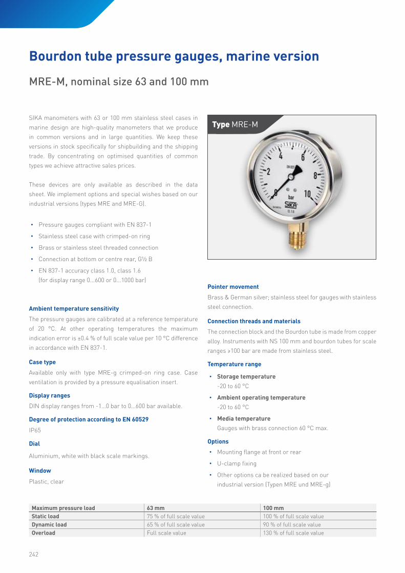
SIKA manometers with 63 or 100 mm stainless steel cases in
marine design are high-quality manometers that we produce
in common versions and in large quantities. We keep these
versions in stock specifically for shipbuilding and the shipping
trade. By concentrating on optimised quantities of common
types we achieve attractive sales prices.
These devices are only available as described in the data
sheet. We implement options and special wishes based on our
industrial versions (types MRE and MRE-G).
• Pressure gauges compliant with EN 837-1
• Stainless steel case with crimped-on ring
• Brass or stainless steel threaded connection
• Connection at bottom or centre rear, G½ B
• EN 837-1 accuracy class 1.0, class 1.6
(for display range 0...600 or 0...1000 bar)
Type Mre-M
Maximum pressure load 63 mm 100 mm
Static load 75 % of full scale value 100 % of full scale value
Dynamic load 65 % of full scale value 90 % of full scale value
Overload Full scale value 130 % of full scale value
Bourdon tube pressure gauges, marine version
MRE-M, nominal size 63 and 100 mm

243
NS = 63 mm
NS = 100 mm NS = 63 mm
NS = 100 mm
Bottom connectionWith rear flange
Bottom connectionWithout mounting flange
Central back connectionWith front flange
Central back connection Without mounting flange
Central back connection Available with u-clamp
Dimensions [mm]
NS D D1 a a1 b b1 b2 c c1 c2 d1 d2 d3 e G g h s s1 s3 SW
63 68 62 13 14 32 32 33 5 2 13 75 85 3.6 - G¼ 58 54 1 1 4.5 14
100 107 99 15.5 14 48 48 49 6 3 20 115 132 5.1 30 G½ 81.5 87 1 1 6 22
Types and dimensions

244
Order code
Order example MREM 3 1 1 315 0 0 G
Bourdon tube pressure gauges, industrial version
Crimped-on ring case MREM
Nominal size
63 mm100 mm
13
Connection thread
G¼ B bottom (63 mm)G½ B bottom (100 mm)G¼ central back connection (63 mm)G½ B central back connection (100 mm)
1152
Connection material
BrassStainless steel (only for 0...1000 bar and 0...1600 bar)
13
Display ranges
-1...0 bar-1...0.6 bar-1...1.5 bar-1...3 bar
315505515525
-1...5 bar-1...9 bar-1...15 bar0...0.6 bar0...1 bar
535545555015025
0...1.6 bar0...2.5 bar0...4 bar0...6 bar0...10 bar
035045055065075
0...16 bar0...25 bar0...40 bar0...60 bar0...100 bar
085095105115125
0...160 bar0...250 bar0...400 bar0...600 bar0...1000 bar
135145155165175
Mounting flangeNoneRear flangeFront flangeU-clamp
0123
Option
None 0
Filled case
Filled case (glycerine) G

-245-
245

246
Type Mreg-KWe manufacture pressure gauges specifically designed for use
in refrigeration and chiller systems and specifically adapted to
this application. They have scales showing both the pressure
and the pressure-dependent evaporation temperature of the
corresponding refrigerant. Some of these pressure gauges
also have additional safety features according to the hazard
classification of the refrigerant.
• Stainless steel crimped ring case
• Bottom or rear connection
• Brass connection (stainless steel for R717)
• EN 837-1 accuracy class 1 (class 1.6 with 63 mm case)
• Standard display ranges -1 to 15 bar, -1 to 24 bar,
-1 to 30 bar
• Standard refrigerants R134a, R404a, R407c, R507, R717
Designed and built for safety
Refrigerants are classified into three groups according to
VBG 20 Sect. 3:
• Group 1:
Non-flammable refrigerants with no harmful impact
on health
• Group 2:
Toxic or corrosive refrigerants and refrigerants with a lower
explosion limit of at least 3.5 % by volume when mixed with
air
• Group 3:
As group 2, but with an explosion limit below 3.5% by
volume
SIKA refrigeration pressure gauges comply with EN 837-1
safety level S2 for refrigerants in groups 1 and 2 and EN 837-1
safety level S3 for refrigerants in group 3.
Bourdon tube pressure gauges, chiller version
Type MREG-K, nominal sizes 63, 80 and 100 mm
Option
Thread 7/16“-20 UNF with tapered seal according to DIN 3866
for solderless connection to 6 mm tubing (¼“ flare)
The provisions of the EN 837-2 standard should be
observed when using pressure gauges.
247
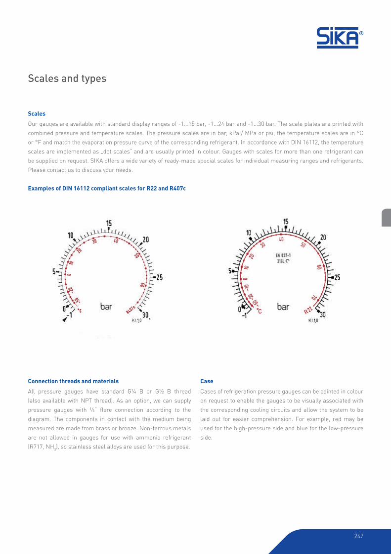
Scales
Our gauges are available with standard display ranges of -1...15 bar, -1...24 bar and -1...30 bar. The scale plates are printed with
combined pressure and temperature scales. The pressure scales are in bar, kPa / MPa or psi; the temperature scales are in °C
or °F and match the evaporation pressure curve of the corresponding refrigerant. In accordance with DIN 16112, the temperature
scales are implemented as „dot scales“ and are usually printed in colour. Gauges with scales for more than one refrigerant can
be supplied on request. SIKA offers a wide variety of ready-made special scales for individual measuring ranges and refrigerants.
Please contact us to discuss your needs.
Connection threads and materials
All pressure gauges have standard G¼ B or G½ B thread
(also available with NPT thread). As an option, we can supply
pressure gauges with ¼“ flare connection according to the
diagram. The components in contact with the medium being
measured are made from brass or bronze. Non-ferrous metals
are not allowed in gauges for use with ammonia refrigerant
(R717, NH3), so stainless steel alloys are used for this purpose.
Scales and types
Examples of DIN 16112 compliant scales for R22 and R407c
Case
Cases of refrigeration pressure gauges can be painted in colour
on request to enable the gauges to be visually associated with
the corresponding cooling circuits and allow the system to be
laid out for easier comprehension. For example, red may be
used for the high-pressure side and blue for the low-pressure
side.
248
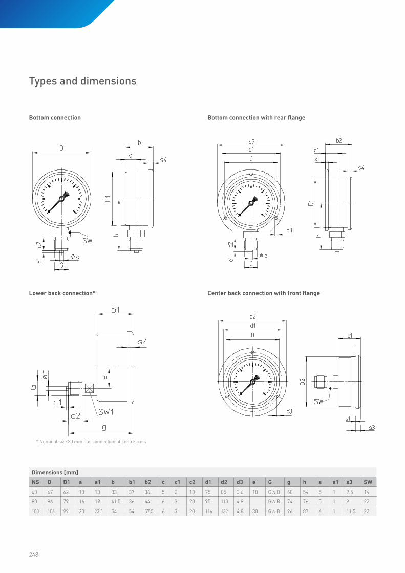
Types and dimensions
Bottom connection Bottom connection with rear flange
Center back connection with front flangeLower back connection*
* Nominal size 80 mm has connection at centre back
Dimensions [mm]
NS D D1 a a1 b b1 b2 c c1 c2 d1 d2 d3 e G g h s s1 s3 SW
63 67 62 10 13 33 37 36 5 2 13 75 85 3.6 18 G¼ B 60 54 5 1 9.5 14
80 86 79 16 19 41.5 36 44 6 3 20 95 110 4.8 G½ B 74 76 5 1 9 22
100 106 99 20 23.5 54 54 57.5 6 3 20 116 132 4.8 30 G½ B 96 87 6 1 11.5 22
249
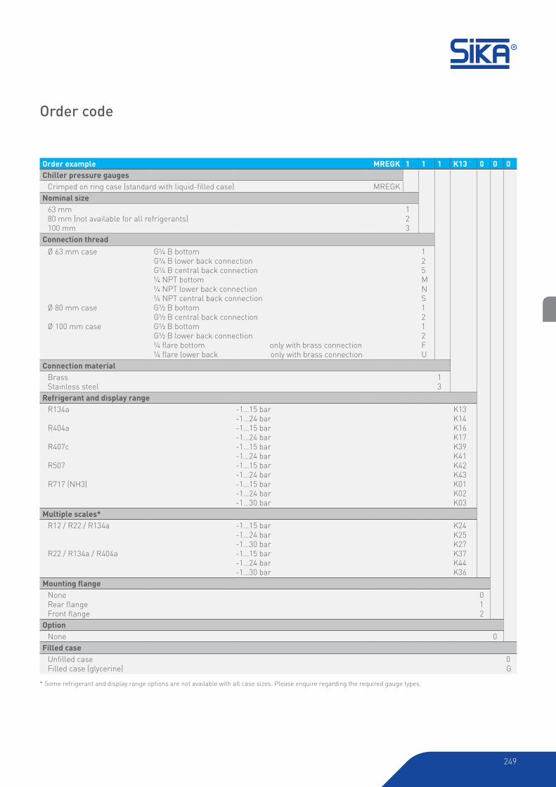
Order code
Order example MREGK 1 1 1 K13 0 0 0
Chiller pressure gauges
Crimped on ring case (standard with liquid-filled case) MREGK
Nominal size
63 mm80 mm (not available for all refrigerants)100 mm
123
Connection thread
Ø 63 mm case
Ø 80 mm case
Ø 100 mm case
G¼ B bottomG¼ B lower back connectionG¼ B central back connection¼ NPT bottom¼ NPT lower back connection¼ NPT central back connectionG½ B bottomG½ B central back connectionG½ B bottomG½ B lower back connection¼ flare bottom only with brass connection¼ flare lower back only with brass connection
125MNS1212FU
Connection material
BrassStainless steel
13
Refrigerant and display range
R134a
R404a
R407c
R507
R717 (NH3)
-1…15 bar-1…24 bar-1…15 bar-1…24 bar-1…15 bar-1…24 bar-1…15 bar-1…24 bar-1…15 bar-1…24 bar-1…30 bar
K13K14K16K17K39K41K42K43K01K02K03
Multiple scales*R12 / R22 / R134a
R22 / R134a / R404a
-1…15 bar-1…24 bar-1…30 bar -1…15 bar-1…24 bar-1…30 bar
K24K25K27K37K44K36
Mounting flangeNoneRear flangeFront flange
012
Option
None 0
Filled case
Unfilled caseFilled case (glycerine)
0G
* Some refrigerant and display range options are not available with all case sizes. Please enquire regarding the required gauge types.

250
Type MrpVersion according to US standard, specifically designed for
process applications in the chemical industry and
in oil and gas applications. Suitable for pressure
measurement with gaseous and liquid media, including
aggressive media, that are not highly viscous.
• Thermoplastic case with integrated rear flange
• connection at bottom ½ NPT
• Stainless steel threaded connection and bourdon tube
• Accuracy compliant with Grade 2A according to
ASME B40.1 (±0.5 %)
• Safety version
Case type
Pressure gauges with safety features similar to EN 837-1 S3,
with solid front and pressure relief back. The case and integrated
rear mounting flange are made from black thermoplastic PBTP.
This material is flame retardant (fire class UL 94 VO) and impact
resistant.
Display range / Scales compliant with ASME B40.1 or EN 873-1
These process pressure gauges are available in many
commonly used ranges from 0...0.6 bar to 0...1000 bar, as well
as the corresponding psi ranges from 0...10 psi to 0...15 000 psi.
Scale plate white aluminium with black scale markings.
Degree of protection according toEN 60529
IP65
Dial
Aluminium, white with black scale markings.
Pointer: Aluminium, adjustable, black
Window
Laminated safety glass
Pointer movement
CrNi-Steel
Connection threads and materials
Connection and bourdon tube made from stainless steel.
Bourdon tube pressure gauges, US process version
Type MRP, nominal size 4½“
Maximum pressure load
Static load Full scale value
Dynamic load 90 % of full scale value
Overload Max. 130 % of full scale value
Temperature range
• Storage temperature
-40 to 70 °C (-20 to 70 °C with filled case)
• Ambient operating temperature
-40 to 60 °C (-20 to 60 °C with filled case)
• Media temperature
100 °C max. (70 °C max. with filled case)
Ambient temperature sensitivity
The pressure gauges are calibrated at a reference temperature
of 20 °C/68 °F. According to the ASME standards the maximum
permissible deviation per 28 °C/50 °F may be up to ±1 %.
Options
• With glycerine filled case
251
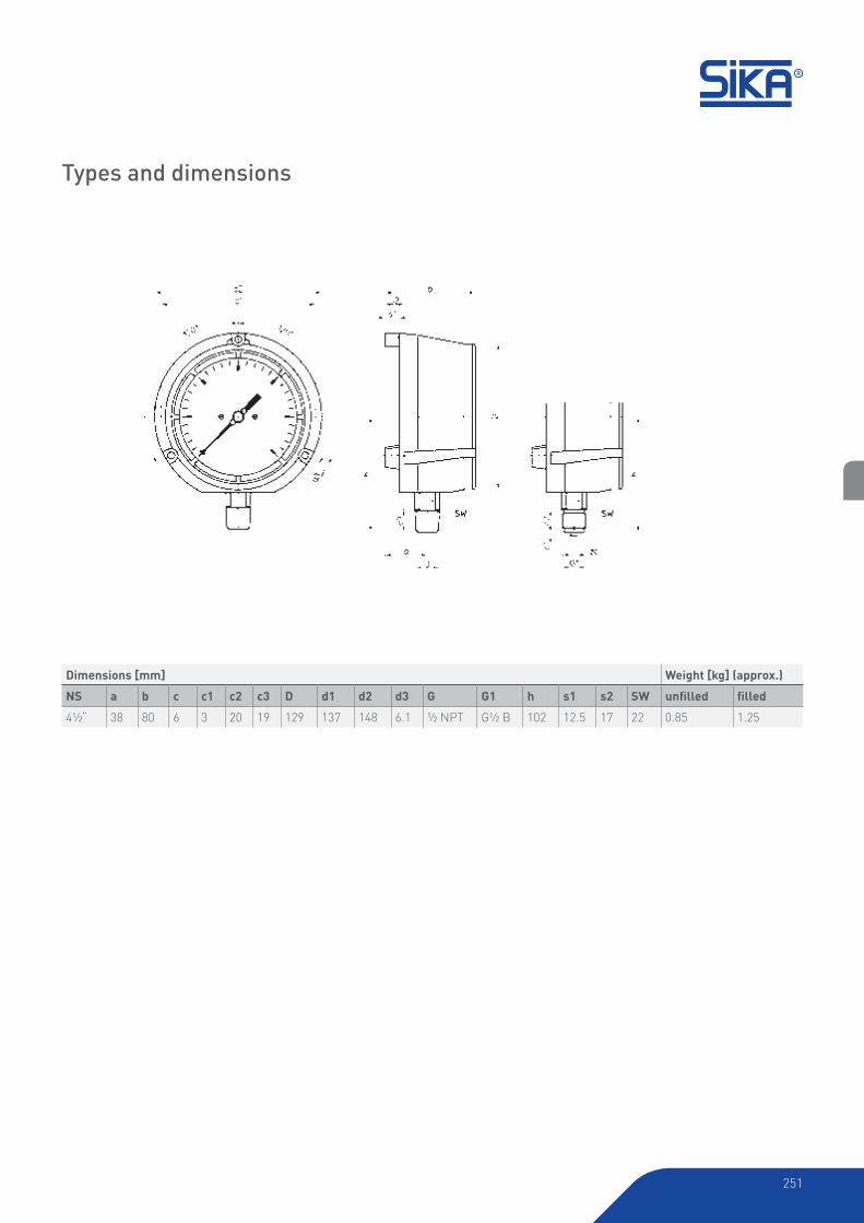
Types and dimensions
Dimensions [mm] Weight [kg] (approx.)
NS a b c c1 c2 c3 D d1 d2 d3 G G1 h s1 s2 SW unfilled filled
4½“ 38 80 6 3 20 19 129 137 148 6.1 ½ NPT G½ B 102 12.5 17 22 0.85 1.25

252
Order code
Order example MRP 3 M 3 015 1 0 0 - P
Bourdon tube pressure gauges,process version according to US standard
Plastic case MRP
Nominal size
4½“ 3
Connection thread
¼ NPT bottom½ NPT bottomG½ B bottom
MB1
Connection material
Stainless steel 3
Display ranges*0...0,6 bar0...1 bar0...1,6 bar0...2,5 bar0...4 bar
015025035045055
0...6 bar0...10 bar0...16 bar0...25 bar0...40 bar
065075085095105
0...60 bar0...100 bar0...160 bar0...250 bar0...400 bar
115125135145155
0...600 bar0...1000 bar * Other ranges (vacuum or pressure, as well as psi) available on request.
165175
Mounting flangeIntegrated rear flange 1
Option
None 0
Filled case
Unfilled caseFilled case (glycerine)
0G
Scale
Scale range in barScale range in psiScale range with dual scale bar & psi
P1

-253-
253
254
Connection threads and materials
The pressure gauges have a stainless steel thread.
Temperature range
• Storage temperature
-20...70 °C
• Ambient operating temperature
-20...60 °C
• Media temperature
Up to 160 °C
Ambient temperature sensivity
The pressure gauges are calibrated at a reference temperature
of 20 °C. At other operating temperatures the maximum
indication error is ±0.4 % of full scale value per 10 °C difference
in accordance with EN 837-1.
Case type
The stainless steel case is available with a crimped-on ring.
Case ventilation is provided by a pressure equalisation insert.
Display ranges
Multiple scales in bar, l/h and USg/h
Degree of protection according to EN 60529
IP65 for filled case with closed pressure equalisation insert
Dial
Aluminium, white with black scale markings.
Pointer: Aluminium, black.
Window
Instrument glass
Pointer movement
CrNi-Steel
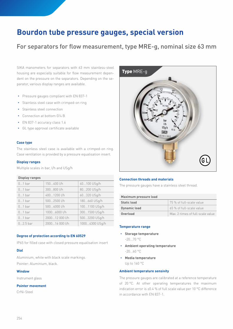
SIKA manometers for separators with 63 mm stainless-steel
housing are especially suitable for flow measurement depen-
dent on the pressure on the separators. Depending on the se-
parator, various display ranges are available.
• Pressure gauges compliant with EN 837-1
• Stainless steel case with crimped-on ring
• Stainless steel connection
• Connection at bottom G¼ B
• EN 837-1 accuracy class 1.6
• GL type approval certificate available
For separators for flow measurement, type MRE-g, nominal size 63 mm
Bourdon tube pressure gauges, special version
Type Mre-g
Maximum pressure load
Static load 75 % of full-scale value
Dynamic load 65 % of full-scale value
Overload Max. 2-times of full-scale value
Display ranges
0...1 bar 150...400 l/h 40...100 USg/h
0...1 bar 300...800 l/h 80...200 USg/h
0...1 bar 400...1200 l/h 60...320 USg/h
0...1 bar 500...2500 l/h 180...660 USg/h
0...1 bar 500...4000 l/h 100...1100 USg/h
0...1 bar 1000...6000 l/h 300...1500 USg/h
0...1 bar 2000...12 000 l/h 500...3200 USg/h
0...2.5 bar 2000...16 000 l/h 1000...4300 USg/h
255
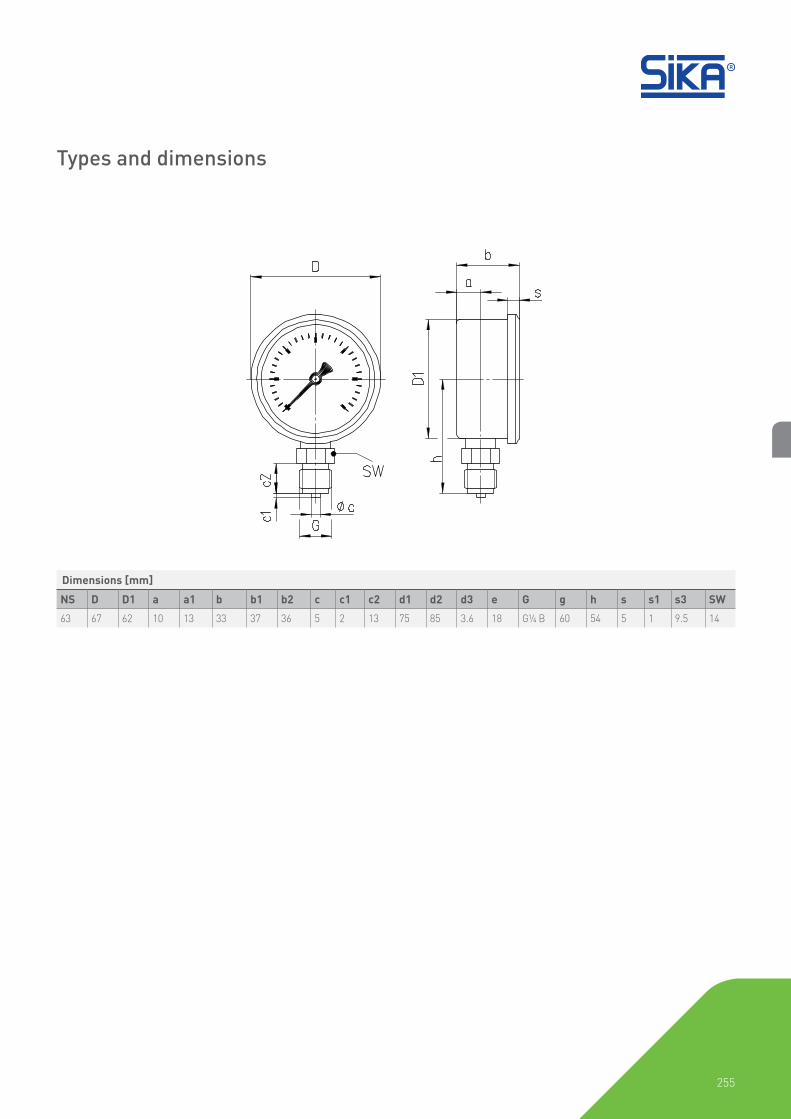
Dimensions [mm]
NS D D1 a a1 b b1 b2 c c1 c2 d1 d2 d3 e G g h s s1 s3 SW
63 67 62 10 13 33 37 36 5 2 13 75 85 3.6 18 G¼ B 60 54 5 1 9.5 14
Types and dimensions

256
Order code
Order example MREG 1 1 1 02513 G DA
Bourdon tube pressure gauges for separators
Crimped on ring case MREG
Nominal size
63 mm 1
Connection thread
G¼ B bottom 1
Connection material
Brass 1
Display range
Pressure Flow rate0...1 bar 2000...12 000 l/h, 500...3200 USg/h0...1 bar 1000...6000 l/h, 3000...1500 USg/h0...1 bar 150...400 l/h, 40...100 USg/h0...1 bar 300...800 l/h, 80...200 USg/h0...1 bar 400...1200 l/h, 60...320 USg/h0...1 bar 500...4000 l/h, 100...1100 USg/h0...2.5 bar 2000...16 000 l/h, 1000...4300 USg/h
02513025230253302543025530254404503
Filled case
Filled case (glycerine) G
Additional product information
Flow indicators DA

-257-
257
258
Case type
The stainless steel case is available with a bayonet ring.
Construction
The instruments are provided with two independently working
measuring systems, each system with its own pressure
connection. The connections are marked with + and - (+ for
the higher pressure, - for the lower pressure). A special duplex
movement with the pointer arbors seated co-axial into each
other transfers the pressure proportional motions of both
Bourdon tubes to the pointers.
Display range
DIN display ranges available from 0…0.6 bar up to 0…600 bar.
Degree of protection according to EN 60529
IP54 (IP65 for filled case).
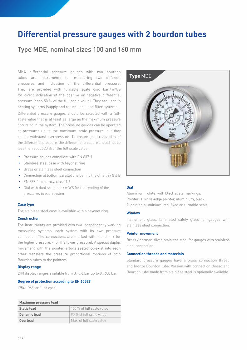
SIKA differential pressure gauges with two bourdon
tubes are instruments for measuring two different
pressures and indication of the differential pressure.
They are provided with turnable scale disc bar / mWS
for direct indication of the positive or negative differential
pressure (each 50 % of the full scale value). They are used in
heating systems (supply and return lines) and filter systems.
Differential pressure gauges should be selected with a full-
scale value that is at least as large as the maximum pressure
occurring in the system. The pressure gauges can be operated
at pressures up to the maximum scale pressure, but they
cannot withstand overpressure. To ensure good readability of
the differential pressure, the differential pressure should not be
less than about 20 % of the full scale value.
• Pressure gauges compliant with EN 837-1
• Stainless steel case with bayonet ring
• Brass or stainless steel connection
• Connection at bottom parallel one behind the other, 2x G½ B
• EN 837-1 accuracy, class 1.6
• Dial with dual scale bar / mWS for the reading of the
pressures in each system
Type MDe
Differential pressure gauges with 2 bourdon tubes
Type MDE, nominal sizes 100 and 160 mm
Dial
Aluminium, white; with black scale markings.
Pointer: 1. knife-edge pointer, aluminium, black.
2. pointer, aluminium, red, fixed on turnable scale.
Window
Instrument glass, laminated safety glass for gauges with
stainless steel connection.
Pointer movement
Brass / german silver, stainless steel for gauges with stainless
steel connection.
Connection threads and materials
Standard pressure gauges have a brass connection thread
and bronze Bourdon tube. Version with connection thread and
Bourdon tube made from stainless steel is optionally available.
Maximum pressure load
Static load 100 % of full scale value
Dynamic load 90 % of full scale value
Overload Max. of full scale value
259
Temperature range
• Storage temperature
-40 to 70 °C (-20 to 70 °C with filled case)
• Ambient operating temperature
-40 to 60 °C (-20 to 60 °C with filled case)
• Media temperature
Gauges with brass connection: 60 °C max.
Gauges with stainless steel connection: 100 °C max.
Ambient temperature sensitivity
The pressure gauges are calibrated at a reference temperature
of 20 °C. At other operating temperatures the maximum
indication error is ±0.4 % of full scale value per 10 °C difference
in accordance with EN 837-1.
Options
• With glycerine filled case
• Customer-specific special scales available with large
order quantities

260
* Unfilled version with fixed front mounting flange with oval holes and separate trim ring.** Filled version with lugs welded to the case and separate trim ring.
Without mounting flangeParallel one behind the other
With front flange, unfilled*Parallel one behind the other
With front flange, filled**Parallel one behind the other
With rear flangeParallel one behind the other
Types and dimensions
Dimensions [mm]
NS D d1 d2 d3 a a1 b b1 c c1 c2 c3
100 100 116 132 4.8 15 19 85 89 6 3 20 19
160 160 178 196 5.8 33 37 104 106.5 6 3 20 19
Dimensions [mm] Weight [kg] (approx)***
NS G G1 h±1 h1±1 k SW s s1 s2 s3 unfilled filled
100 G½ B ½ NPT 87 86 32 22 2 6 6 1 0.90 1.50
160 G½ B ½ NPT 117 116 32 22 2 6 6 1 1.50 3.50
*** Data applies to versions without mounting flange

261
Order example MDE 3 1 3 015 1 0 0
Differential pressure gauges with 2 bourdon tubes
Bayonet ring case MDE
Nominal size
100 mm160 mm
34
Connection thread
G½ B bottom NPT bottomM20 x 1.5
1B3
Connection material
BrassStainless steel
13
Display range
0...0.6 bar0...1 bar0...1.6 bar0...2.5 bar0...4 bar
015025035045055
0...6 bar0...10 bar0...16 bar0...25 bar0...40 bar
065075085095105
0...60 bar0...100 bar0...160 bar0...250 bar0...400 bar
115125135145155
0...600 bar 165
Mounting flangeNoneRear flangeFront flange
012
Option
None 0
Filled case
Unfilled caseFilled case (glycerine)
0G
Order code
262
Window
Instrument glass
Pointer movement
Brass / German silver
Connection threads and materials
Standard pressure gauges have a brass connection thread and
bronze Bourdon tube.
Temperature range
• Storage temperature
-40 to 70 °C
• Ambient operating temperature
-40 to 60 °C
• Media temperature
Gauges with brass connection: 60 °C max. soft soldered
Gauges with stainless steel connection: 100 °C max.
Ambient temperature sensitivity
The pressure gauges are calibrated at a reference temperature
of 20 °C. At other operating temperatures the maximum
indication error is ±0.4 % of full scale value per 10 °C difference
in accordance with EN 837-1.
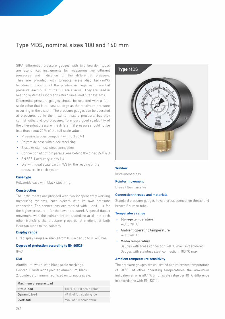
SIKA differential pressure gauges with two bourdon tubes
are economical instruments for measuring two different
pressures and indication of the differential pressure.
They are provided with turnable scale disc bar / mWS
for direct indication of the positive or negative differential
pressure (each 50 % of the full scale value). They are used in
heating systems (supply and return lines) and filter systems.
Differential pressure gauges should be selected with a full-
scale value that is at least as large as the maximum pressure
occurring in the system. The pressure gauges can be operated
at pressures up to the maximum scale pressure, but they
cannot withstand overpressure. To ensure good readability of
the differential pressure, the differential pressure should not be
less than about 20 % of the full scale value.
• Pressure gauges compliant with EN 837-1
• Polyamide case with black steel ring
• Brass or stainless steel connection
• Connection at bottom parallel one behind the other, 2x G½ B
• EN 837-1 accuracy, class 1.6
• Dial with dual scale bar / mWS for the reading of the
pressures in each system
Case type
Polyamide case with black steel ring.
Construction
The instruments are provided with two independently working
measuring systems, each system with its own pressure
connection. The connections are marked with + and - (+ for
the higher pressure, - for the lower pressure). A special duplex
movement with the pointer arbors seated co-axial into each
other transfers the pressure proportional motions of both
Bourdon tubes to the pointers.
Display range
DIN display ranges available from 0…0.6 bar up to 0…600 bar.
Degree of protection according to EN 60529
IP43
Dial
Aluminium, white; with black scale markings.
Pointer: 1. knife-edge pointer, aluminium, black.
2. pointer, aluminium, red, fixed on turnable scale.
Maximum pressure load
Static load 100 % of full scale value
Dynamic load 90 % of full scale value
Overload Max. of full scale value
Type MDs
Type MDS, nominal sizes 100 and 160 mm
263
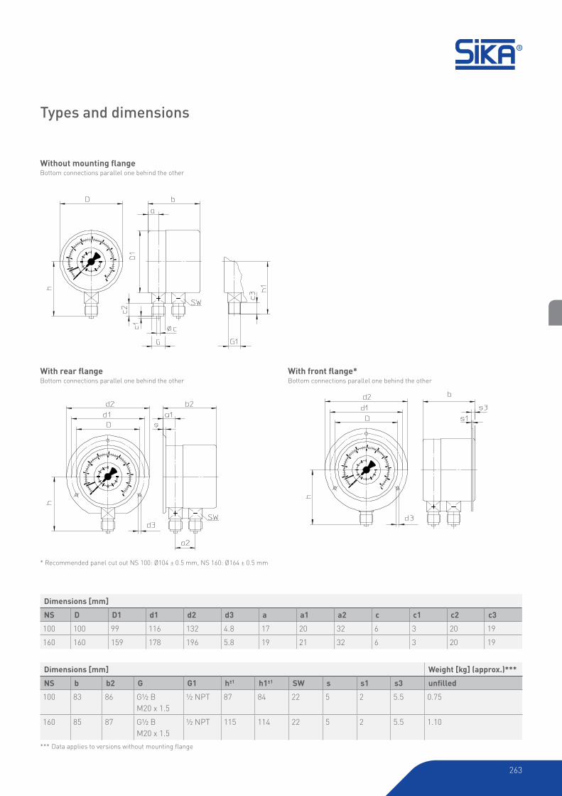
* Recommended panel cut out NS 100: Ø104 ± 0.5 mm, NS 160: Ø164 ± 0.5 mm
Without mounting flangeBottom connections parallel one behind the other
With rear flangeBottom connections parallel one behind the other
With front flange*Bottom connections parallel one behind the other
Types and dimensions
Dimensions [mm]
NS D D1 d1 d2 d3 a a1 a2 c c1 c2 c3
100 100 99 116 132 4.8 17 20 32 6 3 20 19
160 160 159 178 196 5.8 19 21 32 6 3 20 19
Dimensions [mm] Weight [kg] (approx.)***
NS b b2 G G1 h±1 h1±1 SW s s1 s3 unfilled
100 83 86 G½ B
M20 x 1.5
½ NPT 87 84 22 5 2 5.5 0.75
160 85 87 G½ B
M20 x 1.5
½ NPT 115 114 22 5 2 5.5 1.10
*** Data applies to versions without mounting flange
264
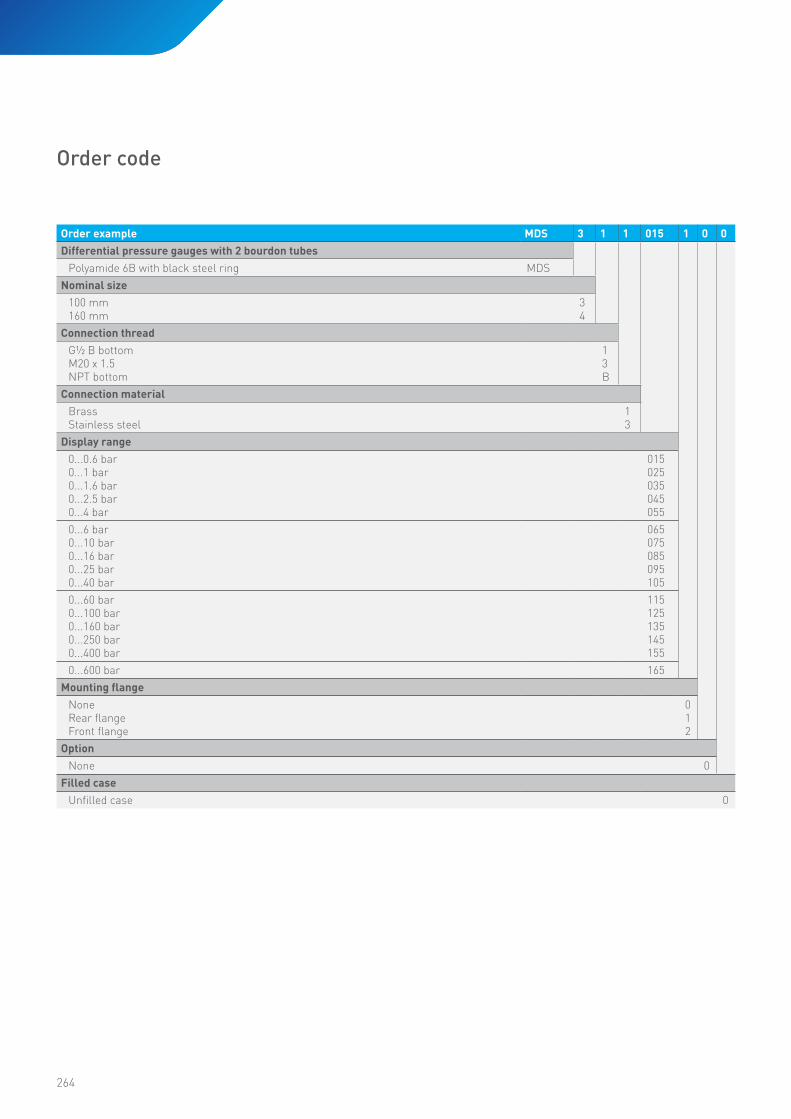
Order example MDS 3 1 1 015 1 0 0
Differential pressure gauges with 2 bourdon tubes
Polyamide 6B with black steel ring MDS
Nominal size
100 mm160 mm
34
Connection thread
G½ B bottomM20 x 1.5NPT bottom
13B
Connection material
BrassStainless steel
13
Display range
0...0.6 bar0...1 bar0...1.6 bar0...2.5 bar0...4 bar
015025035045055
0...6 bar0...10 bar0...16 bar0...25 bar0...40 bar
065075085095105
0...60 bar0...100 bar0...160 bar0...250 bar0...400 bar
115125135145155
0...600 bar 165
Mounting flangeNoneRear flangeFront flange
012
Option
None 0
Filled case
Unfilled case 0
Order code

-265-
265

266
Pressure gauges with horizontal diaphragm allow to find suitable versions for even difficult kinds of media, such as aggressive, contaminated or viscous media. The stainless steel
bayonet ring case is designed for applications where a rust
resistant, sealed case of high chemical resistance is required
(dirty damp, or corrosive atmosphere)..
• Pressure gauges compliant with EN 837-3
• Stainless steel case with bayonet ring
• Stainless steel connection, G½ B
• Connection at bottom, enlarged channel opening in case
of PTFE lining, optional open flange
• EN 837-1 accuracy, class 1.6 (with protecting foil class 2.5)
Maximum pressure load
Static load 100 % of full scale value
Dynamic load 90 % of full scale value
Overload Up to 5-times, max. 40bar
Type Mpe
Diaphragm pressure gauges
Type MPE, nominal sizes 100 and 160 mm
Case type
The stainless steel case has a bayonet ring and is designed to
conform to safety requirements similar to EN 837-1.
Display ranges (EN 837-3)
Display ranges from 0..10 mbar up to 0…40 bar, with PTFE-foil
starting at 0...40 mbar; filled starting at 0...40 mbar available.
Degree of protection according to EN 60529
IP54 (unfilled), IP65 (filled)
Dial
Aluminium, white with black scale markings.
Pointer: Aluminium, black.
Window
Laminated safety glass
Pointer movement
CrNi-Steel
Measuring flange
Flange made of stainless steel.
Display ranges ≤250 mbar = Ø 160 mm
Display ranges ≥400 mbar = Ø 100 mm
Connection threads and materials
Pressure gauges with stainless steel connection are available
with a stainless steel diaphragm (40 to 250 mbar) or a Duratherm
diaphragm (0.4 to 40 bar). In addition, they can optionally be
produced with PTFE lining.
Temperature range
• Storage temperature
-40 to 70 °C (-20 to 70 °C with filled case)
• Ambient operating temperature
-20 to 60 °C
• Media temperature
100 °C max. (70 °C max. with filled case)
Ambient temperature sensitivity
The pressure gauges are calibrated at a reference temperature
of 20 °C. At other operating temperatures indication errors can
be considerable.
Options
• Inlet port orifice up to Ø 10 mm
• Hygienic connection, e.g. according to DIN 11851,
DN 25 to DN 50
• Adjustable pointer, aluminum, black
• Diaphragm with protection foil: PTFE (>40 mbar, vacuum
tight), sealing PTFE; Fine-silver (>160 mbar, vacuum
tight), sealing FPM; Tantalum (>160 mbar, vacuum tight
upon request), sealing PFTE, others upon request
• Up to 10-times overload protection, but max. 40 bar (600
psi) for measuring flange Ø 100 mm (3.94“) max. 2.5 bar (40 psi) for measuring flange Ø 160 mm (6.3“)
• Other filling fluid, silicone oil for temp. down to -40 °C (flange sealing PTFE)
• Version for temperatures >100 °C

267
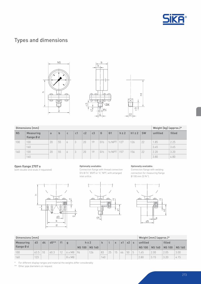
Open flange 2707 a(with double-end studs if requested)
Types and dimensions
Dimensions [mm] Weight [kg] (approx)*
NS Measuring
flange Ø da b c c1 c2 c3 G G1 h ± 2 h1 ± 2 SW unfilled filled
100 100 20 55 6 3 20 19 G½ ½ NPT 127 126 22 1.85 2.25
160 3.45 3.65
160 100 20 55 6 3 20 19 G½ ½ NPT 157 156 22 2.20 3.20
160 3.80 4.80
Dimensions [mm] Weight [kg] (approx)*
Measuring
flange Ø dd3 d4 d5** f1 g h ± 2 k l x x1 x2 s unfilled filled
NS 100 NS 160 NS 100 NS 160 NS 100 NS 160
100 63.5 10 60.3 12 6 x M8 96 126 83 25 15 46 50 5 1.65 2.00 2.05 3.00
160 123 8 x M8 140 2.80 3.15 3.20 4.15
* For different display ranges and material the weights differ considerably
** Other pipe diameters on request
Optionally available:
Connection flange with thread connection G½ B (½“ BSP) or ½“ NPT, with enlarged
inlet orifice.
Optionally available:
Connection flange with welding connection for measuring flange Ø 100 mm (3.94“).

268
Open flanges according to DIN EN 1092-1, DN 15, 20, 25 and 50, PN10 to PN40,Measuring flange Ø d= 160 mm
DN 15, 20 and 25
Measuring flange Ø d= 100 mm
DN 50Measuring flange Ø d= 100 mm
Types and dimensions
Dimensions [mm] Weight [kg] (approx.)*
Measuring
flange Ø dDN d1 d2 f f1 g h ± 2 k x unfilled filled
NS 100 NS 160 NS 100 NS 160 NS 100 NS 160
160 15 95 45 2 16 4 x 14 127 157 65 46 4.15 4.50 4.55 5.50
20 105 58 18 129 159 75 48 4.45 4.80 4.85 5.80
25 115 68 85 4.60 4.95 5.00 5.95
50 165 102 20 4 x 18 137 167 125 56 6.05 6.40 6.45 7.40
Dimensions [mm] Weight [kg] (approx)*
Measuring
flange Ø dDN d1 d2 f g h ± 2 k t x unfilled filled
NS 100 NS 160 NS 100 NS 160 NS 100 NS 160
100 15 99 45 2 4 x M12** 106 157 65 12 30 2.30 2.65 2.70 3.65
20 105 58 75 2.40 2.75 2.80 3.75
25 115 68 103 133 85 22 2.50 2.85 2.90 3.85
50 165 102 4 x Ø18 101 131 125 20 3.60 3.95 4.00 4.95
45° staggered draw
45° staggered draw
45° staggered draw
* For different display ranges and material the weights differ considerably
** With double-end studs M12 x 35 on request

269
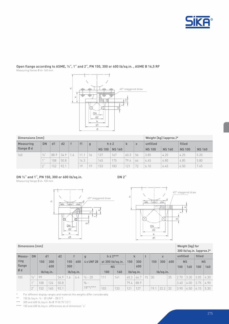
Open flange according to ASME, ½“, 1“ and 2“, PN 150, 300 or 600 lb / sq.in. , ASME B 16,5 RFMeasuring flange Ø d= 160 mm
DN ½“ and 1“, PN 150, 300 or 600 lb / sq.in.Measuring flange Ø d= 100 mm
Dimensions [mm] Weight [kg] (approx.)*
Measuring
flange Ø dDN d1 d2 f f1 g h ± 2 k x unfilled filled
NS 100 NS 160 NS 100 NS 160 NS 100 NS 160
160 ½“ 88.9 34.9 1.6 11.1 16 137 167 60.3 56 3.85 4.20 4.25 5.20
1“ 108 50.8 14.3 145 175 79.4 64 4.45 4.80 4.85 5.80
2“ 152 92.1 19 19 153 183 121 72 6.10 6.45 6.50 7.45
Dimensions [mm] Weight [kg] (approx.)*
Measu-
ring
flangeØ d
DN d1 d2 f g h ± 2**** k t x unfilled filled
150 300
600
150
300
600 4 x UNF 2B at 300 lb / sq.in. 150 300
600
150 300 600 NS NS
NS 100 160 100 160
lb / sq.in. lb / sq.in. 100 160 lb / sq.in. lb / sq.in.
100 ½“ 99 34.9 1.6 6.4 ½ - 20 111 141 60.3 66.7 15 30 35 2.55 2.90 2.95 3.90
1“ 108 124 50.8 ⅝ - 18**/***
79.4 88.9 3.50 3.85 3.90 4.85
2“ 152 165 92.1 103 133 121 127 19.1 22.2 32 3.90 4.25 4.30 5.25
45° staggered draw
45° staggered draw
45° staggered draw
* For different display ranges and material the weights differ considerably
** 150 lb./sq.in: ½ - 20 UNF - 2B (1“)
*** 300 and 600 lb./sq.in: 8x Ø 19 (0.75“) (2“)
**** 150 and 600 lb./sq.in: differences as of dimension “x“
DN 2“

270
Order example MPE 3 1 3 356 0 0 0
Diaphragm pressure gauges unfilledBayonet ring case made of stainless steel MPE
Nominal size
100 mm160 mm
34
Connection thread
G½ B bottomM20 x 1.5 bottom½ NPT bottom
13B
Connection material
Stainless steel 3
Display range
-10...0 mbar Ø 160 mm measuring flange-16...0 mbar Ø 160 mm measuring flange-25...0 mbar Ø 160 mm measuring flange-40...0 mbar Ø 160 mm measuring flange-60...0 mbar Ø 160 mm measuring flange
356366376386396
-100...0 mbar Ø 160 mm measuring flange-160...0 mbar Ø 160 mm measuring flange-250...0 mbar Ø 160 mm measuring flange-1...1.5 bar Ø 100 mm measuring flange-1...3 bar Ø 100 mm measuring flange
406416426515525
-1...0.6 bar Ø 100 mm measuring flange-1...5 bar Ø 100 mm measuring flange-1...9 bar Ø 100 mm measuring flange-1...15 bar Ø 100 mm measuring flange0...0.6 bar Ø 100 mm measuring flange
505535545555015
0...1 bar Ø 100 mm measuring flange0...1.6 bar Ø 100 mm measuring flange0...2.5 bar Ø 100 mm measuring flange0...4 bar Ø 100 mm measuring flange0...6 bar Ø 100 mm measuring flange
025035045055065
0...10 bar Ø 100 mm measuring flange0...16 bar Ø 100 mm measuring flange0...25 bar Ø 100 mm measuring flange0...40 bar Ø 100 mm measuring flange0...60 mbar Ø 160 mm measuring flange
075085095105116
0...100 mbar Ø 160 mm measuring flange0...160 mbar Ø 160 mm measuring flange0...250 mbar Ø 160 mm measuring flange0...400 mbar Ø 160 mm measuring flange
126136146156
Mounting flangeNone 0
Option
None 0
Filled case
Unfilled case 0
Order code

271
Order example MPE 3 1 3 386 0 0 G
Diaphragm pressure gauges filledBayonet ring case made of stainless steel MPE
Nominal size
100 mm160 mm
34
Connection thread
G½ B bottomM20 x 1.5 bottom½ NPT bottom
13B
Connection material
Stainless steel 3
Display range
-160...0 mbar Ø 160 mm measuring flange-250...0 mbar Ø 160 mm measuring flange-1...1.5 bar Ø 100 mm measuring flange-1...3 bar Ø 100 mm measuring flange-1...0.6 bar Ø 100 mm measuring flange
416426515525505
-1...5 bar Ø 100 mm measuring flange-1...9 bar Ø 100 mm measuring flange-1...15 bar Ø 100 mm measuring flange0...0.6 bar Ø 100 mm measuring flange0...1 bar Ø 100 mm measuring flange
535545555015025
0...1.6 bar Ø 100 mm measuring flange0...2.5 bar Ø 100 mm measuring flange0...4 bar Ø 100 mm measuring flange0...6 bar Ø 100 mm measuring flange0...10 bar Ø 100 mm measuring flange
035045055065075
0...16 bar Ø 100 mm measuring flange0...25 bar Ø 100 mm measuring flange0...40 bar Ø 100 mm measuring flange0...160 mbar Ø 160 mm measuring flange0...250 mbar Ø 160 mm measuring flange
085095105136146
0...400 mbar Ø 160 mm measuring flange 156
Mounting flangeNone 0
Option
None 0
Filled case
Filled case (glycerine) G

272
Diaphragm pressure gauges, safety version
Type MPE-S, nominal sizes 100 and 160 mm
Pressure gauges with horizontal diaphragm allow to find suitable versions for even difficult kinds of media, such as aggressive, contaminated or viscous media. The stainless steel
bayonet ring case is designed for applications where a rust
resistant, sealed case of high chemical resistance is required
(dirty damp, or corrosive atmosphere). The gauges conform to
safety class S3 requirements as specified in EN 873-1.
• Pressure gauges compliant with EN 837-3 S3
• Stainless steel case with bayonet ring
• Stainless steel connection, G½ B
• Connections at bottom, with enlarged channel opening
in case of PTFE lining, optional open flange
• EN 837-3 accuracy, class 1.6 (class 2.5 with protection foil,
filled and vacuum ranges))
Maximum pressure load
Static load 100 % of full scale value
Dynamic load 90 % of full scale value
Overload Up to 5-times, max. 40 bar and max. 2.5 bar for flange Ø 160 mm
Type Mpe-s
Case type
The stainless steel case has a bayonet ring and is designed to
conform to safety requirements similar to EN 837-1 S3. The
gauges have a sturdy baffle between the dial plate and the Bourdon tube and connection block. The entire back cover is
designed to blow out.
Display ranges (EN 837-3)
Display range from 0..10 mbar up to 0…40 bar, with PTFE-foil
starting at 0...40 mbar; filled starting at 0...160 mbar up to
40 bar available.
Degree of protection according to EN 60529
IP54 (unfilled), IP65 (filled)
Dial
Aluminium, white with black scale markings.
Pointer: Aluminium, black.
Window
Laminated safety glass
Pointer movement
CrNi-Steel
Measuring flangeFlange made of stainless steel.
Display range ≤ 250 mbar = Ø 160 mm
Display range ≥ 400 mbar = Ø 100 mm
Connection threads and materials
Pressure gauges with stainless steel connection are available
with a stainless steel diaphragm (10 to 250 mbar) or a Duratherm
Options
• Inlet port orifice up to Ø 10 mm
• Hygienic connection, e.g. according to DIN 11851, DN 25 to
DN 50
• Window acryl glass or polycarbonate (only for display
ranges ≥ 0...100 mbar)
• Adjustable pointer, aluminium, black
• Diaphragm with protection foil: PTFE (> 40 mbar, vacuum
tight), sealing PTFE; Fine-silver (> 160 mbar, vacuum
tight), sealing FPM; Tantalum (> 160 mbar, vacuum tight
upon request), sealing PFTE, others upon request
• Up to 10-times overload protection, but max. 40 bar (600
psi) for measuring flange Ø 100 mm (3.94“) max. 2.5 bar
(40 psi) for measuring flange Ø 160 mm (6.3“)
• Other filling fluid, silicone oil for temp. down to -40 °C (flange sealing PTFE)
• Version for temperatures >100 °C
diaphragm (0.4 to 40 bar). In addition, they can optionally be
produced with PTFE lining.
Temperature range
• Storage temperature
-40 to 70 °C (-20 to 70 °C with filled case)
• Ambient operating temperature
-20 to 60 °C
• Media temperature
100 °C max. (70 °C max. with filled case)
Ambient temperature sensitivity
The pressure gauges are calibrated at a reference temperature
of 20 °C. At other operating temperatures indication errors can
be considerable.
273
Open flange 2707 a(with double-end studs if requested)
Types and dimensions
Dimensions [mm] Weight [kg] (approx.)*
NS Measuring
flange Ø da b c c1 c2 c3 G G1 h ± 2 h1 ± 2 SW unfilled filled
100 100 20 55 6 3 20 19 G½ ½ NPT 127 126 22 1.85 2.25
160 3.45 3.65
160 100 20 55 6 3 20 19 G½ ½ NPT 157 156 22 2.20 3.20
160 3.80 4.80
Dimensions [mm] Weight [mm] (approx.)*
Measuring
flange Ø dd3 d4 d5** f1 g h ± 2 k l x x1 x2 s unfilled filled
NS 100 NS 160 NS 100 NS 160 NS 100 NS 160
100 63.5 10 60.3 12 6 x M8 96 126 83 25 15 46 50 5 1.65 2.00 2.05 3.00
160 123 8 x M8 140 2.80 3.15 3.20 4.15
* For different display ranges and material the weights differ considerably
** Other pipe diameters on request
Optionally available:
Connection flange with thread connection G½ B (½“ BSP) or ½“ NPT, with enlarged
inlet orifice.
Optionally available:
Connection flange with welding connection for measuring flange Ø 100 mm (3.94“).

274
Open flange according to DIN EN 1092-1, DN 15, 20, 25 and 50, PN10 to PN40Measuring flange Ø d= 160 mm
DN 15, 20 and 25Measuring flange Ø d= 100 mm
DN 50
Dimensions [mm] Weight [kg] (approx.)*
Measuring
flange Ø dDN d1 d2 f f1 g h ± 2 k x unfilled filled
NS 100 NS 160 NS 100 NS 160 NS 100 NS 160
160 15 95 45 2 16 4 x 14 127 157 65 46 4.15 4.50 4.55 5.50
20 105 58 18 129 159 75 48 4.45 4.80 4.85 5.80
25 115 68 85 4.60 4.95 5.00 5.95
50 165 102 20 4 x 18 137 167 125 56 6.05 6.40 6.45 7.40
Dimensions [mm] Weight [kg] (approx.)*
Measuring
flange Ø dDN d1 d2 f g h ± 2 k t x unfilled filled
NS 100 NS 160 NS 100 NS 160 NS 100 NS 160
100 15 99 45 2 4 x M12** 106 157 65 12 30 2.30 2.65 2.70 3.65
20 105 58 75 2.40 2.75 2.80 3.75
25 115 68 103 133 85 22 2.50 2.85 2.90 3.85
50 165 102 4 x Ø18 101 131 125 20 3.60 3.95 4.00 4.95
* For different display ranges and material the weights differ considerably
** With double-end studs M12 x 35 on request
45° staggered draw
45° staggered draw
45° staggered draw
275
Open flange according to ASME, ½“, 1“ and 2“, PN 150, 300 or 600 lb/sq.in. , ASME B 16,5 RFMeasuring flange Ø d= 160 mm
DN ½“ and 1“, PN 150, 300 or 600 lb/sq.in.Measuring flange Ø d= 100 mm
Dimensions [mm] Weight [kg] (approx.)*
Measuring
flange Ø dDN d1 d2 f f1 g h ± 2 k x unfilled filled
NS 100 NS 160 NS 100 NS 160 NS 100 NS 160
160 ½“ 88.9 34.9 1.6 11.1 16 137 167 60.3 56 3.85 4.20 4.25 5.20
1“ 108 50.8 14.3 145 175 79.4 64 4.45 4.80 4.85 5.80
2“ 152 92.1 19 19 153 183 121 72 6.10 6.45 6.50 7.45
Dimensions [mm] Weight [kg] for
300 lb/sq.in. (approx.)*
Measu-
ring
flangeØ d
DN d1 d2 f g h ± 2*** k t x unfilled filled
150 300
600
150
300
600 4 x UNF 2B at 300 lb/sq.in. 150 300
600
150 300 600 NS NS
NS 100 160 100 160
lb/sq.in. lb/sq.in. 100 160 lb/sq.in. lb/sq.in.
100 ½“ 99 34.9 1.6 6.4 ½ - 20 111 141 60.3 66.7 15 30 35 2.70 3.30 3.05 4.30
1“ 108 124 50.8 ⅝ - 18**/***
79.4 88.9 3.40 4.00 3.75 4.90
2“ 152 165 92.1 103 133 121 127 19.1 22.2 32 3.90 4.50 4.15 5.30
* For different display ranges and material the weights differ considerably
** 150 lb./sq.in: ½ - 20 UNF - 2B (1“)
*** 300 and 600 lb./sq.in: 8x Ø 19 (0.75“) (2“)
**** 150 and 600 lb./sq.in: differences as of dimension “x“
DN 2“
45° staggered draw
45° staggered draw
45° staggered draw

276
Order example MPES 3 1 3 356 0 0 0
Diaphragm pressure gauges unfilledBayonet ring case made of stainless steel MPES
Nominal size
100 mm160 mm
34
Connection thread
G½ B bottomM20 x 1.5 bottom½ NPT bottom
13B
Connection material
Stainless steel 3
Display range
-10...0 mbar Ø 160 mm measuring flange-16...0 mbar Ø 160 mm measuring flange-25...0 mbar Ø 160 mm measuring flange-40...0 mbar Ø 160 mm measuring flange-60...0 mbar Ø 160 mm measuring flange
356366376386396
-100...0 mbar Ø 160 mm measuring flange-160...0 mbar Ø 160 mm measuring flange-250...0 mbar Ø 160 mm measuring flange-1...1.5 bar Ø 100 mm measuring flange-1...3 bar Ø 100 mm measuring flange
406416426515525
-1...0.6 bar Ø 100 mm measuring flange-1...5 bar Ø 100 mm measuring flange-1...9 bar Ø 100 mm measuring flange-1...15 bar Ø 100 mm measuring flange0...0.6 bar Ø 100 mm measuring flange
505535545555015
0...1 bar Ø 100 mm measuring flange0...1.6 bar Ø 100 mm measuring flange0...2.5 bar Ø 100 mm measuring flange0...4 bar Ø 100 mm measuring flange0...6 bar Ø 100 mm measuring flange
025035045055065
0...10 bar Ø 100 mm measuring flange0...16 bar Ø 100 mm measuring flange0...25 bar Ø 100 mm measuring flange0...40 bar Ø 100 mm measuring flange0...60 mbar Ø 160 mm measuring flange
075085095105116
0...100 mbar Ø 160 mm measuring flange0...160 mbar Ø 160 mm measuring flange0...250 mbar Ø 160 mm measuring flange0...400 mbar Ø 160 mm measuring flange
126136146156
Mounting flangeNone 0
Option
None 0
Filled case
Unfilled case 0
Order code
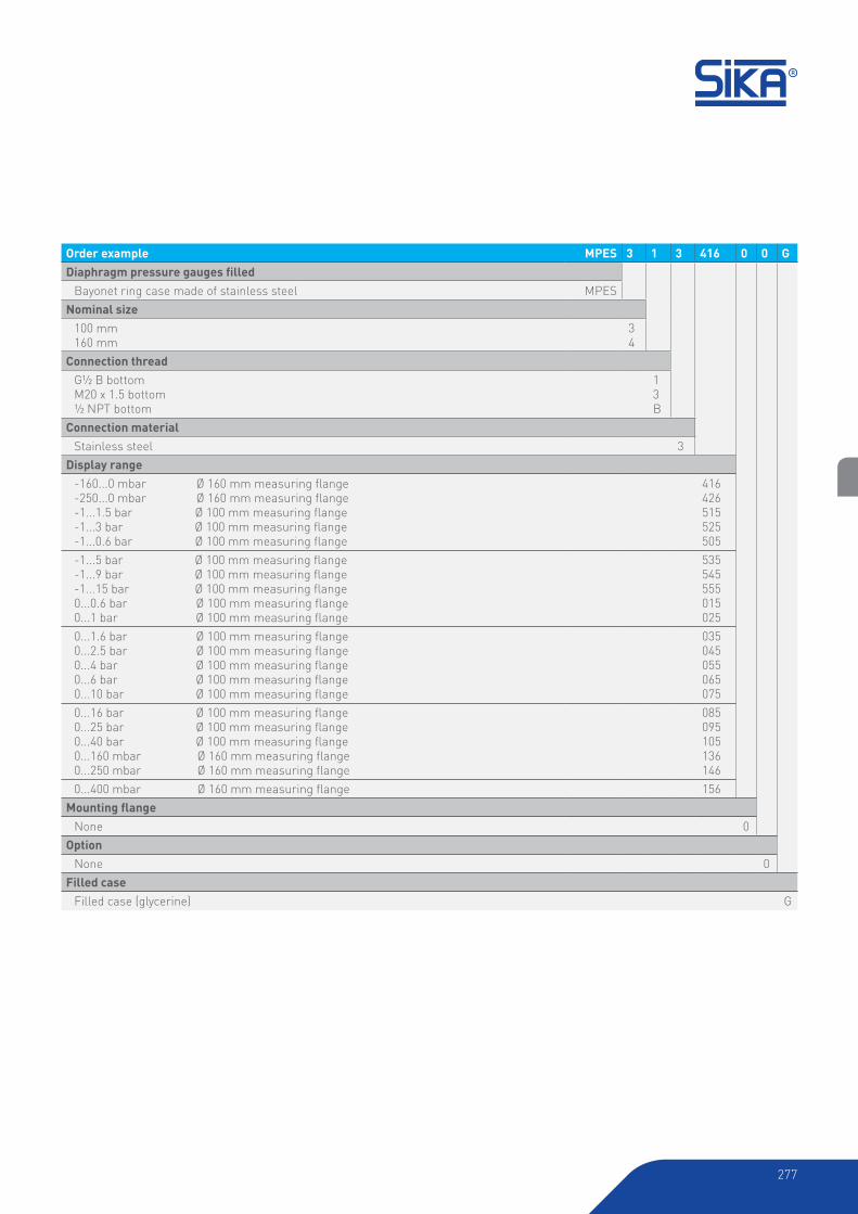
277
Order example MPES 3 1 3 416 0 0 G
Diaphragm pressure gauges filledBayonet ring case made of stainless steel MPES
Nominal size
100 mm160 mm
34
Connection thread
G½ B bottomM20 x 1.5 bottom½ NPT bottom
13B
Connection material
Stainless steel 3
Display range
-160...0 mbar Ø 160 mm measuring flange-250...0 mbar Ø 160 mm measuring flange-1...1.5 bar Ø 100 mm measuring flange-1...3 bar Ø 100 mm measuring flange-1...0.6 bar Ø 100 mm measuring flange
416426515525505
-1...5 bar Ø 100 mm measuring flange-1...9 bar Ø 100 mm measuring flange-1...15 bar Ø 100 mm measuring flange0...0.6 bar Ø 100 mm measuring flange0...1 bar Ø 100 mm measuring flange
535545555015025
0...1.6 bar Ø 100 mm measuring flange0...2.5 bar Ø 100 mm measuring flange0...4 bar Ø 100 mm measuring flange0...6 bar Ø 100 mm measuring flange0...10 bar Ø 100 mm measuring flange
035045055065075
0...16 bar Ø 100 mm measuring flange0...25 bar Ø 100 mm measuring flange0...40 bar Ø 100 mm measuring flange0...160 mbar Ø 160 mm measuring flange0...250 mbar Ø 160 mm measuring flange
085095105136146
0...400 mbar Ø 160 mm measuring flange 156
Mounting flangeNone 0
Option
None 0
Filled case
Filled case (glycerine) G
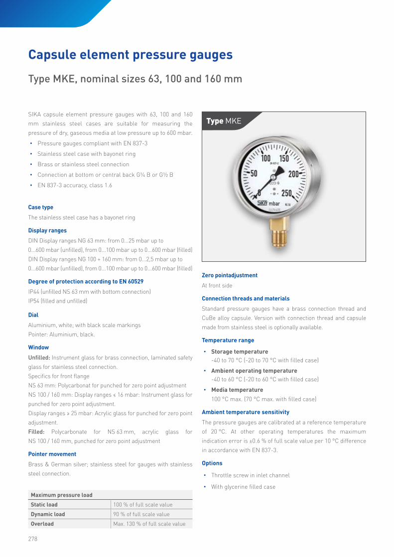
278
SIKA capsule element pressure gauges with 63, 100 and 160
mm stainless steel cases are suitable for measuring the
pressure of dry, gaseous media at low pressure up to 600 mbar.
• Pressure gauges compliant with EN 837-3
• Stainless steel case with bayonet ring
• Brass or stainless steel connection
• Connection at bottom or central back G¼ B or G½ B
• EN 837-3 accuracy, class 1.6
Maximum pressure load
Static load 100 % of full scale value
Dynamic load 90 % of full scale value
Overload Max. 130 % of full scale value
Type MKe
Capsule element pressure gauges
Type MKE, nominal sizes 63, 100 and 160 mm
Case type
The stainless steel case has a bayonet ring
Display ranges
DIN Display ranges NG 63 mm: from 0...25 mbar up to
0...600 mbar (unfilled), from 0...100 mbar up to 0...600 mbar (filled)
DIN Display ranges NG 100 + 160 mm: from 0...2,5 mbar up to
0...600 mbar (unfilled), from 0...100 mbar up to 0...600 mbar (filled)
Degree of protection according to EN 60529
IP44 (unfilled NS 63 mm with bottom connection)
IP54 (filled and unfilled)
Dial
Aluminium, white; with black scale markings
Pointer: Aluminium, black.
Window
Unfilled: Instrument glass for brass connection, laminated safety
glass for stainless steel connection.
Specifics for front flange
NS 63 mm: Polycarbonat for punched for zero point adjustment
NS 100 / 160 mm: Display ranges ≤ 16 mbar: Instrument glass for
punched for zero point adjustment.
Display ranges ≥ 25 mbar: Acrylic glass for punched for zero point
adjustment.
Filled: Polycarbonate for NS 63 mm, acrylic glass for
NS 100 / 160 mm, punched for zero point adjustment
Pointer movement
Brass & German silver; stainless steel for gauges with stainless
steel connection.
Zero pointadjustment
At front side
Connection threads and materials
Standard pressure gauges have a brass connection thread and
CuBe alloy capsule. Version with connection thread and capsule
made from stainless steel is optionally available.
Temperature range
• Storage temperature
-40 to 70 °C (-20 to 70 °C with filled case)
• Ambient operating temperature
-40 to 60 °C (-20 to 60 °C with filled case)
• Media temperature
100 °C max. (70 °C max. with filled case)
Ambient temperature sensitivity
The pressure gauges are calibrated at a reference temperature
of 20 °C. At other operating temperatures the maximum
indication error is ±0.6 % of full scale value per 10 °C difference
in accordance with EN 837-3.
Options
• Throttle screw in inlet channel
• With glycerine filled case

279
Without mounting flange, NS 63Bottom connection
Without mounting flange, NS 63Central back connection
Types and dimensions
With rear flange, NS 63Bottom connection
With rear flange, NS 63Central back connection*
With front flange, NS 63Bottom connection*, **
With front flange, NS 63Central back connection**
* Available upon request, but according to EN 837-3 not recommended
** Front flange with slotted holes, separate cover ring, recommended panel cut out; Ø 67 ± 0,3 mm
NS 63 mm / 100 mm
Case ventilation closeable
NS 160 mm
Blow-out device
Case Ventilation
NS 63 / 100 mm (filled) with
case ventilation closeable.
NS 160 mm (filled) with
Blow-out device. Ventilation
required for internal pressure
compensation.
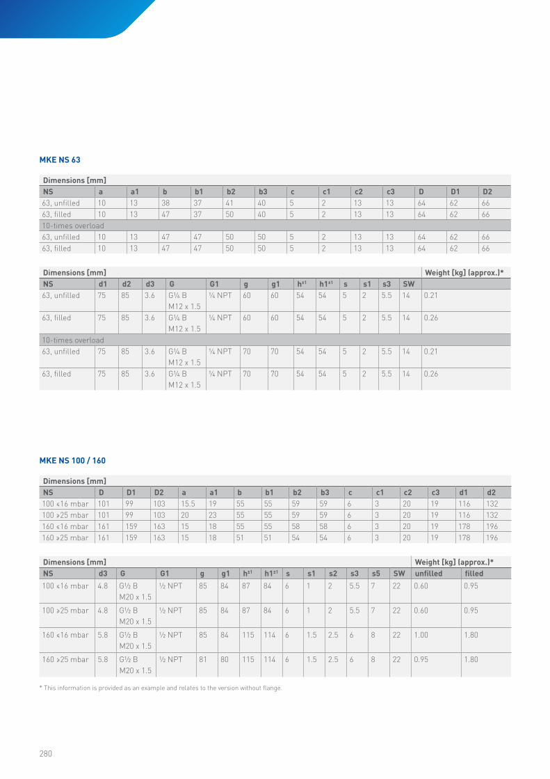
280
Dimensions [mm]
NS D D1 D2 a a1 b b1 b2 b3 c c1 c2 c3 d1 d2
100 ≤16 mbar 101 99 103 15.5 19 55 55 59 59 6 3 20 19 116 132
100 ≥25 mbar 101 99 103 20 23 55 55 59 59 6 3 20 19 116 132
160 ≤16 mbar 161 159 163 15 18 55 55 58 58 6 3 20 19 178 196
160 ≥25 mbar 161 159 163 15 18 51 51 54 54 6 3 20 19 178 196
Dimensions [mm] Weight [kg] (approx.)*NS d3 G G1 g g1 h±1 h1±1 s s1 s2 s3 s5 SW unfilled filled
100 ≤16 mbar 4.8 G½ B
M20 x 1.5
½ NPT 85 84 87 84 6 1 2 5.5 7 22 0.60 0.95
100 ≥25 mbar 4.8 G½ B
M20 x 1.5
½ NPT 85 84 87 84 6 1 2 5.5 7 22 0.60 0.95
160 ≤16 mbar 5.8 G½ B
M20 x 1.5
½ NPT 85 84 115 114 6 1.5 2.5 6 8 22 1.00 1.80
160 ≥25 mbar 5.8 G½ B
M20 x 1.5
½ NPT 81 80 115 114 6 1.5 2.5 6 8 22 0.95 1.80
MKE NS 100 / 160
Dimensions [mm]
NS a a1 b b1 b2 b3 c c1 c2 c3 D D1 D2
63, unfilled 10 13 38 37 41 40 5 2 13 13 64 62 66
63, filled 10 13 47 37 50 40 5 2 13 13 64 62 66
10-times overload
63, unfilled 10 13 47 47 50 50 5 2 13 13 64 62 66
63, filled 10 13 47 47 50 50 5 2 13 13 64 62 66
Dimensions [mm] Weight [kg] (approx.)*NS d1 d2 d3 G G1 g g1 h±1 h1±1 s s1 s3 SW
63, unfilled 75 85 3.6 G¼ B
M12 x 1.5
¼ NPT 60 60 54 54 5 2 5.5 14 0.21
63, filled 75 85 3.6 G¼ B
M12 x 1.5
¼ NPT 60 60 54 54 5 2 5.5 14 0.26
10-times overload
63, unfilled 75 85 3.6 G¼ B
M12 x 1.5
¼ NPT 70 70 54 54 5 2 5.5 14 0.21
63, filled 75 85 3.6 G¼ B
M12 x 1.5
¼ NPT 70 70 54 54 5 2 5.5 14 0.26
MKE NS 63
* This information is provided as an example and relates to the version without flange.

281
Without mounting flange, NS 100 / 160Bottom connection
Without mounting flange, NS 100 / 160Central back connection
With rear flange NS 100 / 160Bottom connection*
* NS 100 rear mounting flange for surface mounting, optionally available with slotted holes according to EN 837-3** Available upon request, but according to EN 837-3 not recommended
*** Filled: welded brackets and removable front flange**** Recommended panel cut out bei NS 100 Ø 104 ± 0,5 mm, NS160 Ø164 ± 0,5mm
With front flange NS 100 / 160Bottom connection**, ***
With rear flange NS 100 / 160Central back connection**
With front flange NS 100 / 160Central back connection***, ****
D
h
a
b
D1
c1
c2
c
G
SW
G1
c3
h1
SW
c
G
c1
c2
g
b1
SW
G1
c3
g1
b1
SW
d1
d2
D
h
d3
lich
ten z
u S
chadeners
atz
. Alle R
G
D2
s2
s3
b b
D
d1
d2
d3
s1
d5
s5Z (2 : 1)
Einbautafel
Z
D2
s2
s3
b1
D
d1
h
d3
d2
d2
118
116
6
s
a1
b2
s
b3
g
Panel
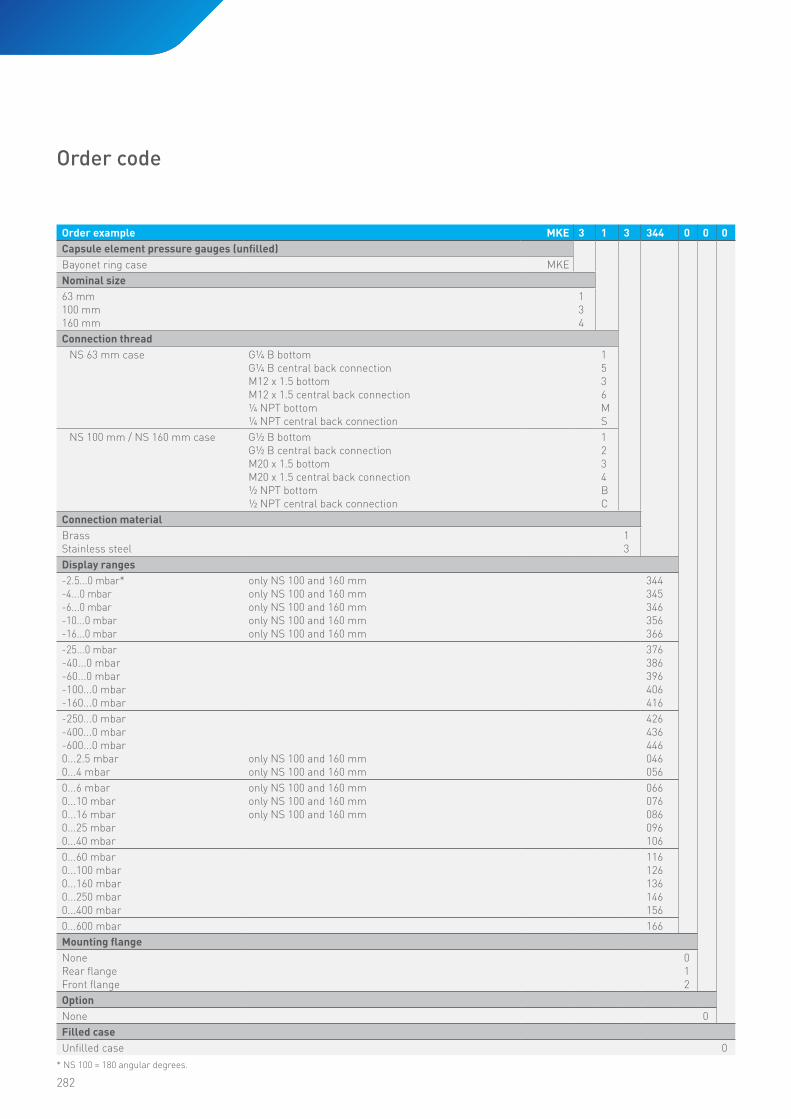
282
Order example MKE 3 1 3 344 0 0 0
Capsule element pressure gauges (unfilled)Bayonet ring case MKE
Nominal size
63 mm100 mm160 mm
134
Connection thread
NS 63 mm case G¼ B bottomG¼ B central back connectionM12 x 1.5 bottomM12 x 1.5 central back connection¼ NPT bottom¼ NPT central back connection
1536MS
NS 100 mm / NS 160 mm case G½ B bottomG½ B central back connectionM20 x 1.5 bottomM20 x 1.5 central back connection½ NPT bottom½ NPT central back connection
1234BC
Connection material
BrassStainless steel
13
Display ranges
-2.5...0 mbar*-4...0 mbar-6...0 mbar-10...0 mbar-16...0 mbar
only NS 100 and 160 mmonly NS 100 and 160 mmonly NS 100 and 160 mmonly NS 100 and 160 mmonly NS 100 and 160 mm
344345346356366
-25...0 mbar-40...0 mbar-60...0 mbar-100...0 mbar-160...0 mbar
376386396406416
-250...0 mbar-400...0 mbar-600...0 mbar0...2.5 mbar0...4 mbar
only NS 100 and 160 mmonly NS 100 and 160 mm
426436446046056
0...6 mbar 0...10 mbar0...16 mbar0...25 mbar0...40 mbar
only NS 100 and 160 mmonly NS 100 and 160 mmonly NS 100 and 160 mm
066076086096106
0...60 mbar0...100 mbar0...160 mbar0...250 mbar0...400 mbar
116126136146156
0...600 mbar 166
Mounting flangeNoneRear flangeFront flange
012
Option
None 0
Filled case
Unfilled case 0
Order code
* NS 100 = 180 angular degrees.

283
Order example MKE 3 1 3 406 0 0 G
Capsule element pressure gauges (filled)Bayonet ring case MKE
Nominal size
63 mm100 mm160 mm
134
Connection thread
NS 63 mm G¼ B bottomG¼ B central back connectionM12 x 1.5 bottomM12 x 1.5 central back connection¼ NPT bottom¼ NPT central back connection
1536MS
NS 100 mm / NS 160 mm G½ B bottomG½ B central back connectionM20 x 1.5 bottomM20 x 1.5 central back connection½ NPT bottom½ NPT central back connection
1234BC
Connection material
BrassStainless steel
13
Display ranges
-100...0 mbar -160...0 mbar-250...0 mbar-400...0 mbar-600...0 mbar
406416426436446
0...100 mbar 0...160 mbar0...250 mbar0...400 mbar0...600 mbar
126136146156166
Mounting flangeNoneRear flangeFront flange
012
Option
None 0
Filled case
Filled case (glycerine) G
Natalie Lundie
HP Stamp