MECHANICAL ONLINE SYSTEM FOR CLEANING HEAT EXCHANGER...
8
MECHANICAL ONLINE SYSTEM FOR CLEANING HEAT EXCHANGER TUBES BY SPONGE RUBBER BALLS (TAPROGGE-SYSTEM) R. Kleinebrahm 1 1 TAPROGGE GmbH, Schliemannstr. 2-14, 58300 Wetter, Germany, [email protected] ABSTRACT Cooling waters used in power stations or industrial plants contain dissolved and unsolved substances which can significantly vary in both quantity and composition. Undesired deposition of these substances on tube surfaces is designated as micro fouling. Normally several fouling mechanisms occur in heat exchanger tubes at the same time and intensify. Fouling impairs the heat transfer in heat exchanger tubes. As a result, the efficiency of heat exchangers and of the overall process decreases. To avoid unplanned outages and take advantage of an additional opportunity of recognizing problems at early stage, online cleaning procedure with sponge rubber balls for prevention and removal of deposits in heat exchanger tubes, like the TAPROGGE-System, is advisable. This paper provides a practical insight into the possibilities and benefits resulting from the operation of online cleaning system furthermore, it will be demonstrated that cleaning balls also promoted the formation of protective layers in tubes. INTRODUCTION The commonality of the tube bundle heat exchangers, which are treated in this paper, is that they are operated with cooling water, which is passed through tubes to cool a second fluid. The differences are the geometry, the current conduction and the physical properties of the fluids in tube bundle heat exchangers, but for this consideration basically the tube material and the type and properties of the cooling water. Usually, three different material types are used as tube material: Copper alloys, such as copper-nickel or brass materials, stainless-steels or titanium, very rarely also aluminium compounds. [6] Cooling water systems are divided into two categories: Once-through and circuit cooling water systems. The sources of cooling water for once-through cooling systems are, for example, river, brackish or seawater. Circuit cooling systems are divided into open and closed systems and the corresponding source for make-up water, for example, pond, well or seawater [1]. These two aspects alone (kind of cooling water and tube material) may account for almost thirty different fouling problems. [6] The generic term fouling is divided into macro and micro fouling. Micro fouling comprises bio fouling (e.g. bacteria), sedimentation (e.g. sand) and the precipitate of salts (e.g. lime). Usually micro fouling causes a layer on the tube surface consisting of salts or bacteria. Moreover, it is possible that sediments enter this layer. Macro fouling designates coarse particles, which block or plug system parts, like tubes. It is classified according to its source: biological, like mussels, or industrial sources, like synthetics. Frequently, macro fouling provides optimal conditions for micro fouling, for instance, lower flow rates. [6] Fig. 1 Examples of bio fouling (a), corrosion products (b), biological macro fouling (c) and lime layer (d). Examples of the various types of fouling are shown in Fig. 1. Fig. 1a shows so-called tubular worms which encapsulate in the tube. This hard encapsulation provides ideal protection against external influences. Fig. 1b shows an example of corrosion. Nickel dissolves from the copper- nickel material due to a poor covering layer formation. The tube surface roughness increases. An example of macro fouling is shown in Fig. 1c. A shell is jammed in the tube inlet and thus blocks the tube. Fig. 1d shows a typical example of micro fouling by scaling. A complete top layer of calcium carbonate is formed. This covering layer is built up in several phases. Two phases can be seen here. The initiation of or tendency to different fouling mechanisms is determined by the type of cooling water, too. While circuit cooling systems are mainly responsible for micro fouling, like concentration of ingredients, the main Heat Exchanger Fouling and Cleaning – 2017 ISBN: 978-0-9984188-0-3; Published online www.heatexchanger-fouling.com 240
Transcript of MECHANICAL ONLINE SYSTEM FOR CLEANING HEAT EXCHANGER...

MECHANICAL ONLINE SYSTEM FOR CLEANING HEAT EXCHANGER TUBES BY
SPONGE RUBBER BALLS (TAPROGGE-SYSTEM)
R. Kleinebrahm1
1 TAPROGGE GmbH, Schliemannstr. 2-14, 58300 Wetter, Germany, [email protected]
ABSTRACT
Cooling waters used in power stations or industrial plants
contain dissolved and unsolved substances which can
significantly vary in both quantity and composition.
Undesired deposition of these substances on tube surfaces is
designated as micro fouling. Normally several fouling
mechanisms occur in heat exchanger tubes at the same time
and intensify. Fouling impairs the heat transfer in heat
exchanger tubes. As a result, the efficiency of heat
exchangers and of the overall process decreases. To avoid
unplanned outages and take advantage of an additional
opportunity of recognizing problems at early stage, online
cleaning procedure with sponge rubber balls for prevention
and removal of deposits in heat exchanger tubes, like the
TAPROGGE-System, is advisable. This paper provides a
practical insight into the possibilities and benefits resulting
from the operation of online cleaning system furthermore, it
will be demonstrated that cleaning balls also promoted the
formation of protective layers in tubes.
INTRODUCTION
The commonality of the tube bundle heat exchangers,
which are treated in this paper, is that they are operated with
cooling water, which is passed through tubes to cool a second
fluid. The differences are the geometry, the current
conduction and the physical properties of the fluids in tube
bundle heat exchangers, but for this consideration basically
the tube material and the type and properties of the cooling
water.
Usually, three different material types are used as tube
material: Copper alloys, such as copper-nickel or brass
materials, stainless-steels or titanium, very rarely also
aluminium compounds. [6]
Cooling water systems are divided into two categories:
Once-through and circuit cooling water systems. The sources
of cooling water for once-through cooling systems are, for
example, river, brackish or seawater. Circuit cooling systems
are divided into open and closed systems and the
corresponding source for make-up water, for example, pond,
well or seawater [1]. These two aspects alone (kind of cooling
water and tube material) may account for almost thirty
different fouling problems. [6]
The generic term fouling is divided into macro and micro
fouling. Micro fouling comprises bio fouling (e.g. bacteria),
sedimentation (e.g. sand) and the precipitate of salts (e.g.
lime). Usually micro fouling causes a layer on the tube
surface consisting of salts or bacteria. Moreover, it is possible
that sediments enter this layer. Macro fouling designates
coarse particles, which block or plug system parts, like tubes.
It is classified according to its source: biological, like
mussels, or industrial sources, like synthetics. Frequently,
macro fouling provides optimal conditions for micro fouling,
for instance, lower flow rates. [6]
Fig. 1 Examples of bio fouling (a), corrosion products (b),
biological macro fouling (c) and lime layer (d).
Examples of the various types of fouling are shown in
Fig. 1. Fig. 1a shows so-called tubular worms which
encapsulate in the tube. This hard encapsulation provides
ideal protection against external influences. Fig. 1b shows an
example of corrosion. Nickel dissolves from the copper-
nickel material due to a poor covering layer formation. The
tube surface roughness increases. An example of macro
fouling is shown in Fig. 1c. A shell is jammed in the tube
inlet and thus blocks the tube. Fig. 1d shows a typical
example of micro fouling by scaling. A complete top layer of
calcium carbonate is formed. This covering layer is built up
in several phases. Two phases can be seen here.
The initiation of or tendency to different fouling
mechanisms is determined by the type of cooling water, too.
While circuit cooling systems are mainly responsible for
micro fouling, like concentration of ingredients, the main
Heat Exchanger Fouling and Cleaning – 2017
ISBN: 978-0-9984188-0-3; Published online www.heatexchanger-fouling.com 240
problem in once-through cooling systems is, for example, the
ingress of macro fouling, like mussels or sand.
Which fouling mechanisms occur in heat exchanger
tubes also depends on the tube material and its surface
condition. The rougher a material, the better can the deposits
adhere and grow. Irrespective of the material, particularly
ribbed tubes have this disadvantage.
Due to the natural toxicity of copper, copper-alloyed
tubes are rarely affected by bio fouling (macro and micro
fouling). However, there is an increased risk of corrosion. In
the case of stainless-steels and titanium, the corrosion risk is
rather low, but there is an increased problem of bio fouling,
both macro and micro fouling.
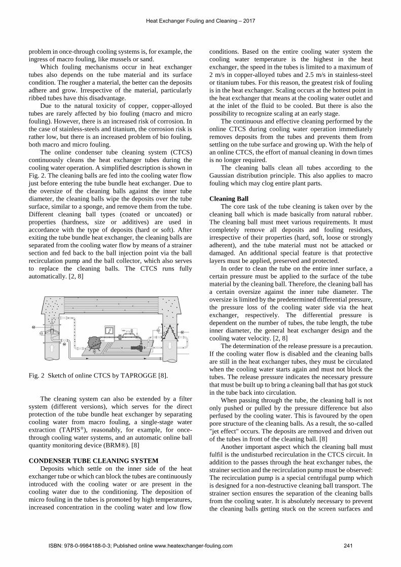
The online condenser tube cleaning system (CTCS)
continuously cleans the heat exchanger tubes during the
cooling water operation. A simplified description is shown in
Fig. 2. The cleaning balls are fed into the cooling water flow
just before entering the tube bundle heat exchanger. Due to
the oversize of the cleaning balls against the inner tube
diameter, the cleaning balls wipe the deposits over the tube
surface, similar to a sponge, and remove them from the tube.
Different cleaning ball types (coated or uncoated) or
properties (hardness, size or additives) are used in
accordance with the type of deposits (hard or soft). After
exiting the tube bundle heat exchanger, the cleaning balls are
separated from the cooling water flow by means of a strainer
section and fed back to the ball injection point via the ball
recirculation pump and the ball collector, which also serves
to replace the cleaning balls. The CTCS runs fully
automatically. [2, 8]
Fig. 2 Sketch of online CTCS by TAPROGGE [8].
The cleaning system can also be extended by a filter
system (different versions), which serves for the direct
protection of the tube bundle heat exchanger by separating
cooling water from macro fouling, a single-stage water
extraction (TAPIS®), reasonably, for example, for once-
through cooling water systems, and an automatic online ball
quantity monitoring device (BRM®). [8]
CONDENSER TUBE CLEANING SYSTEM
Deposits which settle on the inner side of the heat
exchanger tube or which can block the tubes are continuously
introduced with the cooling water or are present in the
cooling water due to the conditioning. The deposition of
micro fouling in the tubes is promoted by high temperatures,
increased concentration in the cooling water and low flow
conditions. Based on the entire cooling water system the
cooling water temperature is the highest in the heat
exchanger, the speed in the tubes is limited to a maximum of
2 m/s in copper-alloyed tubes and 2.5 m/s in stainless-steel
or titanium tubes. For this reason, the greatest risk of fouling
is in the heat exchanger. Scaling occurs at the hottest point in
the heat exchanger that means at the cooling water outlet and
at the inlet of the fluid to be cooled. But there is also the
possibility to recognize scaling at an early stage.
The continuous and effective cleaning performed by the
online CTCS during cooling water operation immediately
removes deposits from the tubes and prevents them from
settling on the tube surface and growing up. With the help of
an online CTCS, the effort of manual cleaning in down times
is no longer required.
The cleaning balls clean all tubes according to the
Gaussian distribution principle. This also applies to macro
fouling which may clog entire plant parts.
Cleaning Ball
The core task of the tube cleaning is taken over by the
cleaning ball which is made basically from natural rubber.
The cleaning ball must meet various requirements. It must
completely remove all deposits and fouling residues,
irrespective of their properties (hard, soft, loose or strongly
adherent), and the tube material must not be attacked or
damaged. An additional special feature is that protective
layers must be applied, preserved and protected.
In order to clean the tube on the entire inner surface, a
certain pressure must be applied to the surface of the tube
material by the cleaning ball. Therefore, the cleaning ball has
a certain oversize against the inner tube diameter. The
oversize is limited by the predetermined differential pressure,
the pressure loss of the cooling water side via the heat
exchanger, respectively. The differential pressure is
dependent on the number of tubes, the tube length, the tube
inner diameter, the general heat exchanger design and the
cooling water velocity. [2, 8]
The determination of the release pressure is a precaution.
If the cooling water flow is disabled and the cleaning balls
are still in the heat exchanger tubes, they must be circulated
when the cooling water starts again and must not block the
tubes. The release pressure indicates the necessary pressure
that must be built up to bring a cleaning ball that has got stuck
in the tube back into circulation.
When passing through the tube, the cleaning ball is not
only pushed or pulled by the pressure difference but also
perfused by the cooling water. This is favoured by the open
pore structure of the cleaning balls. As a result, the so-called
"jet effect" occurs. The deposits are removed and driven out
of the tubes in front of the cleaning ball. [8]
Another important aspect which the cleaning ball must
fulfil is the undisturbed recirculation in the CTCS circuit. In
addition to the passes through the heat exchanger tubes, the
strainer section and the recirculation pump must be observed:
The recirculation pump is a special centrifugal pump which
is designed for a non-destructive cleaning ball transport. The
strainer section ensures the separation of the cleaning balls
from the cooling water. It is absolutely necessary to prevent
the cleaning balls getting stuck on the screen surfaces and
Heat Exchanger Fouling and Cleaning – 2017
ISBN: 978-0-9984188-0-3; Published online www.heatexchanger-fouling.com 241

thereby disturbing the recirculation of other cleaning balls.
The strainer configuration can vary in angle and screen bar
width. In addition, the cleaning ball can be adjusted in size
and hardness. This shows that the design and function of the
cleaning balls is an extremely complex process which must
consider the CTCS as a whole. [8]
In addition, the different types of fouling and tube
materials in the heat exchanger must be observed. In the case
of copper-alloyed tubes, for example, it is important that an
oxide layer is formed to protect the material from corrosive
attack. Therefore a cleaning ball without any abrasive effect
is recommended.
In the case of titanium or stainless-steel tubes, the tube
surfaces are very smooth, a slight abrasive effect is necessary
to achieve a sufficient cleaning effect. Cleaning balls
provided with polishing agents help keeping these tubes
clean. The polishing agent has a lower hardness than the tube
material and thus acts only as fouling abrasive. [8]
There are two different basic cleaning ball types for
typical materials in tube bundle heat exchangers. Moreover,
there are further possibilities to increase the abrasiveness of
the cleaning balls. For this purpose, basic cleaning ball types
are coated with different materials, such as polishing agents,
synthetic granulate or corundum. The coating can be applied
as total or as ring which effects in different ways. For a better
distribution over the tube sheet, cleaning ball types with
different sinking velocities are produced. Thus, the upper and
lower tubes are reached in the same way. If necessary, a
mixture of different types may also be recommended. [6, 8]
Experience has shown that the cleaning balls have a
regular life time of up to four weeks. Within this time, the
cleaning balls show two different typical wear patterns,
depending on the tube surface condition.
In smooth tubes with a roughness of up to 5 μm, no more
abrasion is present and the cleaning balls are not worn down.
The wear of the cleaning balls is caused by the continuous
mechanical load in the tubes, on the screen of the strainer
section, in the ball recirculation pump, in the piping, and also
by various additives and characteristics of the cooling water.
The diameters of the cleaning balls remain constant. The
cleaning balls only become softer. This wear mechanism is
typical for stainless-steel and titanium tubes.
Copper alloyed tubes typically have a higher roughness.
The wear pattern is determined by the abrasion of the
cleaning ball surface. The cleaning ball is oriented in the heat
exchanger tube according to the least resistance. In order to
clean the heat exchanger tubes effectively, the cleaning balls
must have an oversize of at least 0.5 mm in diameter. Typical
wear phases are shown in Fig. 3.
Fig. 3 wear phases of cleaning balls, as a result of tube
roughness.
In the first wear phase, the cleaning balls are cigar-
shaped. The cleaning ball is oriented with the smallest
diameter along the tube surface. The contact surface of the
cleaning ball on the roughness surface is thereby increased.
However, the smallest ball diameter and thus the contact
pressure and the effect of the cleaning ball are significantly
lower. For this type of cleaning balls, it is recommended to
replace the cleaning balls in order to maintain the cleaning at
an effective and efficient level, because starting from this
wear phase the ball diameter is smaller than required.
In the second wear phase, the cleaning ball has an oval
shape. The smallest ball diameter lies only with the heat
exchanger tube inner diameter. The maximum diameter also
decreases with time. The cleaning balls are no longer
effective.
In the third wear phase, a round shape is obtained again.
The cleaning ball diameter is smaller than the smallest inner
diameter of the heat exchanger tubes. The cleaning ball has
no more cleaning effect.
As far as worn cleaning balls are concerned, there is
another problem besides the poor cleaning effect. Cleaning
balls that are both too small and too soft are pushed through
the screen bars of the strainer section more easily by the
cooling water flow and thus disappear from the system.
These are then found in the cooling tower or the
corresponding water box.
When cleaning balls in stainless-steel or titanium tubes
have a cigar shape, this is a strong indication that hard
deposits are present in the tubes, whereby tube roughness
increases. The cleaning ball is much more than just a cleaning
tool, it is also an indicator of any changes and deposits in the
heat exchanger tubes and thus for the entire heat exchanger.
PROTECTION LAYER
By reason of the high thermal conductivity
(100 - 110 W/m K, at 20 °C), the corrosion resistance
(corrosion rate ≤ 0.01 mm/a) and the favourable price,
copper-alloyed tubes, such as material 2.0470 or 2.0460,
were used in heat exchangers in the past. Their resistance to
corrosive attack is caused by the formation of self-oxide
layers. However, this protective layer is only surface-
covering and resistant in salt-free cooling waters without any
tendency to form deposits. The copper oxide layer has a
thickness of up to 5 μm. [3]
In chloride-rich cooling waters, the oxides of the
protective layer are replaced by chlorides which increase the
rate of corrosion [4]. The local increase in the electron
conductivity increases the risk of pitting corrosion. Solid
deposits, such as, calcium carbonate, or biological
decomposition products, can also cause pitting corrosion. In
this case, the establishment of an external protection layer is
a successful measure.
On account of the susceptibility to corrosion of copper-
alloyed tubes, stainless-steels, like 1.4301, 1.4401 or 1.4436,
have more and more been used since the 1960s. Their poorer
thermal conductivity is almost eliminated by the lower wall
thickness. The stainless-steels also form a passive layer
which protects the material against corrosive attacks. This
passive layer is an oxide film with a thickness of 1 to 4 nm
[3]. Special care is required in the case of deposits because
Heat Exchanger Fouling and Cleaning – 2017
ISBN: 978-0-9984188-0-3; Published online www.heatexchanger-fouling.com 242

areas of corrosion and pitting can form. The same applies to
clogged cooling tubes. Due to the low flow rate and the
prevention of cleaning, the corrosion potential increases. [3]
Another option is to use titanium tubes. Their poor
thermal conductivity is also compensated by the reduced wall
thickness. Titanium is protected against corrosive attack by a
passive layer. A special feature of the protective layers of
stainless-steel and titanium tubes is the rapid renewal after
mechanical injuries in oxygen-containing cooling waters. [3]
Cleaning process with protection layer
In the case of aggressive cooling waters, such as
seawater, it is important to protect the heat exchanger tubes,
especially copper-alloyed tubes, from corrosive attack. An
iron-rich protective layer can be applied to the tube surface
using iron sulphate dosing system. This is done in two
phases: First, the layer is applied and then obtained. This
means that the iron sulphate dosing must be continued
otherwise the protective layer is destroyed again.
The thicker the protective layer is the better the corrosion
resistance of the tube material. However, the saturation is
obtained from a certain strength, approximately 2 mg/cm². In
addition, the fouling rate increases with increasing strength
of the protective layer because the natural toxicity of copper
decreases. Furthermore, the task of the heat exchanger must
also be considered. The stronger the protective layer the
poorer the heat transfer. It is therefore absolutely necessary
to form a very thin yet effective protective layer. [5]
The mechanism of iron sulphate dosing is based on the
solubility of the salt. The oxidation of the iron ions from the
dissolved iron sulphate produces colloidal iron(III)oxide-
hydroxide, which accumulates on the surface of the tube. [5]
4 Fe2++ 8 OH-+ O2 → 4 FeO(OH) + 2 H2O (1)
In order to obtain a compact, homogeneous, thin and
adherent layer for protecting the tube material, the
coordination between the iron sulphate dosing and the
operation of an online CTCS is important. The optimized
operation of the cleaning system in conjunction with the iron
sulphate dosing (intermittently), results in a reddish-brown
protection layer with a thickness of 10 to 50 μm. This
protection layer provides a good corrosion protection and
causes low heat transfer losses (Fig. 4b). [5]
Fig. 4 Protection layer formation as a function of the
online CTCS [5].
Without online CTCS the protective layer is soft,
voluminous and porous. The heat transfer loss is up to 60 %
(Fig. 4a). Continuous cleaning with online CTCS results in a
compact, glossy and homogeneous surface of the protective
layer (Fig. 4c). However, these two protective layer types
(Fig. 4a and c) tend to burst in the event of dry downtimes.
Intermittent cleaning provides a good countermeasure,
resulting in a dull, reddish brown layer, which is less
sensitive to decommissioning and drying out. A successful
operation with copper-alloyed tubes in conjunction with
seawater is a cleaning mode of one hour a day. The cleaning
system is adjusted to the usual ball frequency of 12 balls per
tube per hour. According to the distribution of the cleaning
balls in the heat exchanger, all heat exchanger tubes are
cleaned mechanically 6 - 24 times a day by cleaning balls. [6]
In order for the iron sulphate protective layer to adhere
optimally to heat exchanger tube surface, various cooling
water conditions, such as pH-value, suspended solid fraction
or temperature, must be satisfied. The tube material, the tube
surface condition, the iron sulphate dosing and the sponge
rubber cleaning procedure have also a considerable influence
on formation of the optimum protective layer.
Iron(III)oxide-hydroxide is readily soluble in water in an
acidic environment but is almost insoluble in a basic milieu.
The ideal pH-value for forming and maintaining the
protective layer is 8 [5].
The formation of iron(III)oxide-hydroxide is an
endothermic reaction. From a temperature of 20 °C, which is
usually achieved in heat exchangers (cooling water side), the
reaction rate is sufficient. The cooling water inlet
temperature is a variable which the plant operator cannot
influence. During the winter months a suitable protective
layer is difficult to apply with temperatures below 6 °C, for
example, in the Northern Europe region. [5]
The formation of the optimum protective layer can be
prevented by means of various particles in the cooling water
such as sediments, dust or lime precipitates. The dissolved
iron ions can bind to the particles and are thus no longer
available for the protective layer. The particles can also be
incorporated into the protective layer. As a result, the
protective layer becomes damaged and inhomogeneous. The
presence of particles must be prevented. [5]
Other factors are dissolved oxygen which is required for
the reaction and inorganic compounds such as sulphides,
ammonia or manganese, which shifts the reaction.
Before the protective layer is applied, the surface must
be clean and free from deposits. Corrosion areas must be
removed. If an intact protective layer already exists, this
should be kept. If it is damaged, however, the layer should be
removed and corundum balls should be used. Given that
corundum is harder than copper-alloyed materials, corundum
balls are both deposit and material abrasive. This also applies
to aluminium-based tube materials. For this reason it is
absolutely important to ensure that corundum balls are used
correctly and not permanently. Ideally an inspection is
performed to verify the tube condition before the start of the
corundum ball cleaning procedure. In general, cleaning with
sponge rubber balls must be carried out at least before the
application of the protective layer in order to remove loose
deposits. [5]
Heat Exchanger Fouling and Cleaning – 2017
ISBN: 978-0-9984188-0-3; Published online www.heatexchanger-fouling.com 243

For cleaning procedure during iron sulphate dosing, the
sponge rubber ball is used without any abrasive effect. The
sponge rubber cleaning is the instrument for the balance
between the maintenance of the good heat transfer and the
prevention of corrosion. The optimal cleaning frequency with
sponge rubber balls is influenced by the various local
conditions. The properties of the protective layer crucially
depend on the cleaning frequency and duration. An
intermittent cleaning frequency, like up to a few hours per
day, is recommended as far as possible. However, in most
cases the cleaning frequency is one hour per day. [6]
The proper protective layer must be monitored
continuously. For this purpose regular visual checks are
suitable. Another possibility, which also brings about much
more detailed results, is the extraction of tubes with
subsequent metallurgical examination. However, the
extracted tube should be a representative tube so that the
results can be transferred to the entire heat exchanger.
In order to perform an on-line check of the formation of
the protection layer with aid of iron sulphate in copper-
alloyed tubes it is suitable to determine the copper content in
the cooling water outlet.
According to this measurement method, suspended
copper is determined, which is an indication of corrosion
products. Copper content is increased by a corundum ball
cleaning, as corrosion products are removed from the heat
exchanger tube surface. During the formation of the
protective layer, the copper content in the cooling water
outlet is reduced.
Fig. 5 Copper content (dots) as a function of the iron
sulphate dosing (grey areas) [5].
Fig. 5 shows an example of the interplay between copper
content and iron sulphate dosing during the protective layer
application. First, the copper content is over 50 ppb. In the
course of the iron sulphate dosing, a first protective layer can
be successfully be applied. The iron sulphate dosing is
carried out in each case over a period of twelve hours. The
influence of the iron sulphate dosage on the copper content is
obvious and is demonstrated by the decrease of the copper
emission to almost 10 ppb. Also after dosing, the copper
content decreases even further. This shows the slow constant
build-up of the protective layer in the heat exchanger tube,
due to the sufficient concentration of iron sulphate in the
cooling water. The pause interval between two dosing
periods results from the system. When the copper content
increases, iron sulphate is dosed again. In this case the
interval is 8 - 13 hours. After 70 hours, the copper content in
the cooling water output is less than 5 ppb. Now it is to be
assumed that the protective layer is applied and the phase of
the protective layer conservation is starting.
Other possibilities for checking the formation of the
protection layer are the eddy current test and the
measurement of the polarization resistance [5].
Possible problems of uniform protective layer formation
occur particularly in the inlet area of the heat exchanger
tubes. If the protective layer is not formed sufficiently,
erosion corrosion becomes possible. Countermeasures are
the reduction of the amount of cooling water, the reduction
of the ball frequency or the increase of iron sulphate dosing.
In the case of a reduction of the heat transfer, which can
be recognized by the deterioration of both the U-value and
the terminal temperature difference (TTD), either the iron
sulphate dosing is reduced or the ball frequency is increased
or both are supplemented. [2]
Due to the fact that, especially in power stations, just
little attention is paid to the cooling water side of heat
exchanger tubes, comparatively rough protection layer
structures result. These are first evident by the increased
cleaning ball wear. With a roughness of, for example, 50 μm,
the ball life time is reduced to only two days. These rough
protection layers must be removed. With the help of a
corundum ball cleaning procedure, the rough protection
layers are removed and the tubes are smoothed. By the use of
corundum cleaning balls with subsequent polishing cleaning
balls an end roughness of 8 μm is achieved. The life time of
the cleaning ball is thus increased again to up to four weeks.
If the cleaning balls are not checked carefully and exchanged
in time, they will lose their effect and efficiency. After only
four months, the protective layer can be damaged again in
such a way that the ball life time is again two days. Due to
the damaged protective layer, corrosion can also occur again.
The following procedure is recommended for the
build-up of a cooling water side protection layer with good
corrosion protection and long cleaning ball life time:
1. Preparation of the heat exchanger tube surface by means
of corundum balls for smoothing the surface and
removing deposits and corrosion products. A maximum
tube material roughness of 10 μm is applied.
2. Intermittent tube cleaning procedure, depending on the
conditions of the system and cooling water type, with
sponge rubber balls, polishing balls or a mixture of both
types of cleaning balls.
3. For circuit cooling water systems, a copper inhibitor can
also be added.
The smoothing of the tube surface by means of a
corundum ball cleaning and the subsequent continuous
effective cleaning with polishing balls is also recommended
for the heat transfer tube materials like stainless-steel and
titanium. The passive-protective layers of these tube
materials are built so quickly and comprehensively with the
help of the oxygen in the cooling water that no further
protective layers have to be applied for these tube materials.
In the case of titanium, corrosion problems have been
Heat Exchanger Fouling and Cleaning – 2017
ISBN: 978-0-9984188-0-3; Published online www.heatexchanger-fouling.com 244

unknown so far. Corrosion is also rare in stainless-steel heat
exchangers. The cause of corrosion in stainless-steel tubes
are deposits on the tube surface or clogged tubes. This can be
successfully be prevented by means of a continuous,
effective tube cleaning, if necessary with an additional debris
filter installed directly in front of the heat exchanger for the
protection of the same.
Cleanliness factor
An important factor for verifying the condition of the
heat exchanger is the cleanliness factor (CF). The CF is
defined by the ratio of the actual and design heat transfer
coefficients:
CF = Uactual
Udesign (2)
With the help of the actual heat transfer coefficient
compared to the design heat transfer coefficient, degradation
of the heat flow, for example by deposits or too thick
protection layers, is detected. The CF is 95 - 100 % for clean
heat exchanger tubes for stainless-steel and titanium
materials. For copper-alloyed tubes, depending on the type of
cooling water, for sea and brackish water 85 – 95 % and for
cooling tower and fresh water 95 – 100 % are reached. The
CF can be measured directly in the heat exchanger tube
which is a very accurate way of determination. A further
possibility is to calculate this indirectly via the transferred
heat flow, by means of steam temperature or steam pressure,
cooling water temperatures, cooling water flow rate and other
system values. Due to the various parameters, with the
respective measurement errors, this method is imprecise.
Often the measured steam data does not produce any
thermodynamically meaningful results. As a result of the
necessary assumptions, further error sources are added. [6]
In a power plant, the heat transfer coefficient was
measured directly in the heat exchanger tube (Fig. 6). The
influence of the cleaning balls is shown on basis of this data.
In the months from September to the beginning of
November, a maximum CF of 87 % is reached. By the use of
a new cleaning ball charge, characterized by the grey triangle,
this CF is reached.
Fig. 6 Recording of the CF, measured directly in the heat
exchanger tube, over time, including display of the
ball exchange (grey triangles and dot) [5].
Within one week after exchange of cleaning balls, the CF
and thus the cleaning effect remains constant at 85 - 87 %.
The heat exchanger tubes are cleaned well. Subsequently, the
wear of the cleaning balls and thus the clear reduction in the
cleaning effect can be seen. The CF decreases continuously.
This means that the heat exchanger tubes are no longer
sufficiently cleaned. Contamination of heat exchanger tubes
increases. The CF decreases to 80 %. The cleaning ball
exchange interval is three to five weeks and is much too long.
To achieve continuously effective cleaning, the cleaning ball
exchange interval should be reduced to one week.
Due to poor result for the CF, a CF of 95 – 100 % is
expected. The calculation of the cleaning balls was checked
again. In the middle of November the optimized cleaning ball
type was used, shown with the help of the grey dot. In this
case the ball diameter was adjusted, among other things. This
increased the CF to 96 %. Immediately after addition of the
new optimized cleaning balls the CF drops again. This is due
to very strong contamination and the associated high cleaning
ball wear. For this reason, the cleaning ball exchange must
first take place more quickly until the deposits from the tubes
have been completely removed. [5]
This example demonstrates the importance of the timely
exchange and the correct layout of cleaning balls and the
influence of the cleaning ball wear on the efficiency of the
cleaning in the heat exchanger. Even when using non-optimal
cleaning balls, the CF is increased by 6 % by the use of a new
cleaning ball charge. The increase with the help of the
optimized cleaning ball resulted in a further increase of
almost 10 %. If the cleaning is carried out correctly, the heat
exchanger is kept clean and the heat transfer is optimized.
Efficiency enhancement
The heat transfer impairs due to clogged or polluted heat
exchanger tubes. The discharge heat quantity, of the fluid to
be cooled, decreases. The required temperature cannot be
achieved. To compensate this, the cooling water flow may be
adjusted. The poorer the heat transfer, the more cooling water
is required. Only a certain proportion is compensated for by
means of the cooling water flow, that is also limited, because
the temperature increases despite an increased amount of
cooling water. For power stations with turbine condensers,
this means that the steam temperature and thus the steam
pressure in the condenser increase. By reducing the vacuum,
the entire circuit process is affected, and the power output of
the power plant is reduced.
In a power plant, with a design power output of
1033 106 W and a design vacuum on the steam side in the
condenser of 7600 Paabs, data was recorded as shown in Table
1. The power output, the steam pressure in the condenser and
the cooling water flow are measurements. Among other data
from these measured data, the calculated loss data, which is
respectively related to the loss of the vacuum, and the CF,
which describes the state of the heat exchanger tubes at the
same time, are pointed. The pure loss data of the steam
pressure and the power output are determined by the
difference between the actually measured data and the design
data. Depending on the loss of the steam pressure and the loss
of the power output, the average loss of the power results in
0.07 102 %/Pa respectively 0.74 104 W/Pa.
Heat Exchanger Fouling and Cleaning – 2017
ISBN: 978-0-9984188-0-3; Published online www.heatexchanger-fouling.com 245

Table 1: Loss of power output as a function of condenser
steam pressure.
load pressure flowcw loss CF
106 W 102 Paabs kg/s 10-2 %/Pa 104 W/Pa %
1 003 116.4 7 380 0.072 0.748 91.0
1 007 110.3 7 156 0.075 0.773 88.1
1 010 104.8 7 440 0.077 0.794 90.4
1 013 102.2 7 296 0.076 0.782 88.8
1 017 97.1 7 276 0.074 0.766 87.7
1 019 95.4 7 322 0.070 0.727 88.1
1 022 91.2 7 085 0.068 0.701 85.3
1 026 86.3 7 482 0.063 0.654 89.2
1 029 82.7 7 428 0.065 0.673 87.7
In accordance to Table 1 it seems that the CF and the
vapor pressure loss are independent of each other. This is due
to the strong influence of the cooling water flow. In this case,
the CF was not measured directly in the heat exchanger tube
but was calculated with the aid of the transferred heat flow.
As already shown in Eq. (2), the CF is dependent on the
actual and the design heat transfer coefficients. The heat
transfer coefficient is determined according to the Eq. (3).
U = mcw ∙ cp,cw
Acond ∙ ln (
Ts- Tin,cw
Ts- Tout,cw) (3)
The following connections of the variables result from
the assumption that the specific heat capacity (cp,cw), the heat
transfer area (Acond) and the cooling water inlet temperature
(Ti,cw) are constant. The steam temperature increases with
decreasing vacuum. The actual heat transfer coefficient drops
and thus the CF. With decreasing cooling water outlet
temperature (To,cw), the transferred heat quantity, the heat
transfer coefficient and the CF decrease. If the cooling water
flow is increased, the transferred heat quantity can be
increased again, thus the heat transfer coefficient is again
increased and the CF becomes apparently better. This does
not reflect the reality, but compensates for the poorer heat
transfer with more cooling water. This is also the reason why
the CF partially increases despite vacuum loss. Despite better
CF the tube condition still remains in a non-optimal state.
The cooling water inlet temperature is dependent on the
season. With decreasing cooling water inlet temperature, the
transferred heat quantity, heat transfer coefficient and CF
increase. There are better conditions in winter than in
summer months.
Table 2: Data from typical power station losses related to
condenser vacuum (GEC Alsthom case study) [7].
Type of unit Performance variation Output difference
106 W 10-2 %/Pa 104 W/Pa
330 0.07 0.23
600 0.09 0.54
900 0.12 1.08
The power output losses from Table 1 are also confirmed
by a case study by GEC Alsthom (Table 2). There are similar
contexts. The efficiency loss is not just related to the power
output of the power plant, but also CO2 emissions are
important factors and are gaining importance. Resulting from
a continuous loss of the vacuum of only 1000 Paabs in turbine
condenser is a power loss of 7.4 106 W results. With the
assumption of specific CO2-emission of 1 10-3 kg/Wh and an
operating time of 6000 h/a this results in a CO2-emission of
43 106 kg/a. This could be saved just by a clean turbine
condenser, at the same power output. [7]
CONCLUSIONS
For tube bundle heat exchangers which are operated with
cooling water, the use of online CTCS is the state of the art.
If they are operated without sufficient attention larger
disturbances may arise which could be minimized by a better
and timely consideration. Examples such as corrosion or bad
protective layer formation have been explained. For each
system, different operating modes for online CTCS result
from individual circumstances.
The wear behaviour of the cleaning balls determines the
state of the tubes and also of the corresponding protective
layer in a manner of approximation. The CF is an indication
of the cleanliness and condition of the heat exchanger tubes.
The aim of the online cleaning systems is to keep the heat
exchanger tubes clean and to allow as high heat transfer as
possible. This also increases the life time of the heat
exchangers and their tubes and manually cleaning procedures
of heat exchanger tubes are no longer necessary.
Furthermore, the efficiency of the heat exchanger remains
constant at a good level. In order to achieve this, the cleaning
ball must be optimal adjusted to the system, which means the
components of the CTCS, heat exchanger, and cooling water
conditions.
NOMENCLATURE
A Area, m²
BRM Ball Recirculation Monitor
CF Cleanliness Factor, %
cp specific heat capacity, J/kg K
CTCS Condenser Tube Cleaning System
d diameter, m
m Mass flow, kg/s
T Temperature, K
TAPIS TAPROGGE Intake System
TTD Terminal temperature difference, K
U U-Value, thermal Transmittance, W/m² K
Subscript
abs absolute
actual measurement values
cb cleaning ball
cond condenser
cw cooling water
design design values
s steam
i inner
in inlet
out outlet
Heat Exchanger Fouling and Cleaning – 2017
ISBN: 978-0-9984188-0-3; Published online www.heatexchanger-fouling.com 246

REFERENCES
[1] Bott, T. R., 1995, Fouling of Heat Exchangers,
Elsevier science B.V., Netherlands.
[2] Müller-Steinhagen, H. et al., 2001, Handbuch
Wärmeübertrager-Reinigungssysteme, pp. 163-205.
[3] Czolkoss, W., Fichte, W., Schliethoff, K., 1991,
Deckschichtstrukturen auf Kondensatoroberflächen, Der
Maschinenschaden Vol. 64 Heft 5.
[4] North, R.-F., Pryor, H.-J., 1970, The Influence of
Corrosion Product Structure on the Corrosion Rate of Cu-Ni-
Alloys, Corrosion Science 10, pp. 297-311.
[5] Glaze, F. J., Eimer, K., 1985, The combined use of
TAPROGGE sponge ball cleaning and ferrous sulphate
injection, TAPROGGE Technical Report 85-27.
[6] Czolkoss, W., 1992, Recommendations for the
selection of cleaning balls and optimal cleaning frequency,
TAPROGGE Technical Report 92-30.
[7] Paren, J., Pouzenc, C., 1991, Design of power
station condensers, GEC Alsthom Technical Review No. 6,
pp. 19-38.
[8] Website of TAPROGGE GmbH, Wetter;
www.taprogge.de
Heat Exchanger Fouling and Cleaning – 2017
ISBN: 978-0-9984188-0-3; Published online www.heatexchanger-fouling.com 247