Mechanical Fasteners - LHE theory.pdf · Mechanical Fasteners ... designate bolt and screw thread...
30
Mechanical Fasteners Mechanical Fasteners – – Tensile and Shear Stress Areas Tensile and Shear Stress Areas Lecture 28 Lecture 28 Engineering 473 Engineering 473 Machine Design Machine Design
Transcript of Mechanical Fasteners - LHE theory.pdf · Mechanical Fasteners ... designate bolt and screw thread...

Mechanical Fasteners Mechanical Fasteners ––Tensile and Shear Stress AreasTensile and Shear Stress Areas
Lecture 28Lecture 28
Engineering 473Engineering 473Machine DesignMachine Design
Threaded FastenersThreaded Fasteners
BoltBolt � Threaded fastener designed to pass through holes in mating members and to be secured by tightening a nut from the end opposite the head of the bolt.
ScrewScrew � Threaded fastener designed to be inserted through a hole in one member and into a threaded hole in a mating member.
Mott, Fig. 18-1
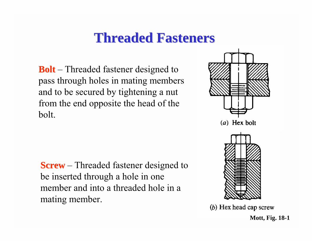
BoltsBolts
Mott, Fig. 18-2
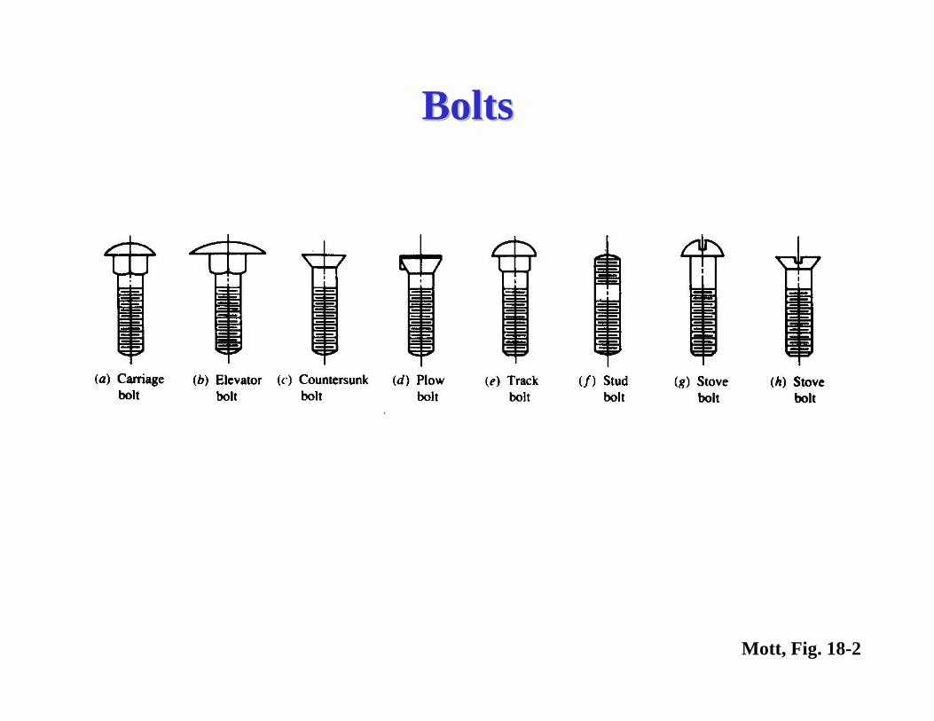
Machine ScrewsMachine Screws
Mott, Fig. 18-3
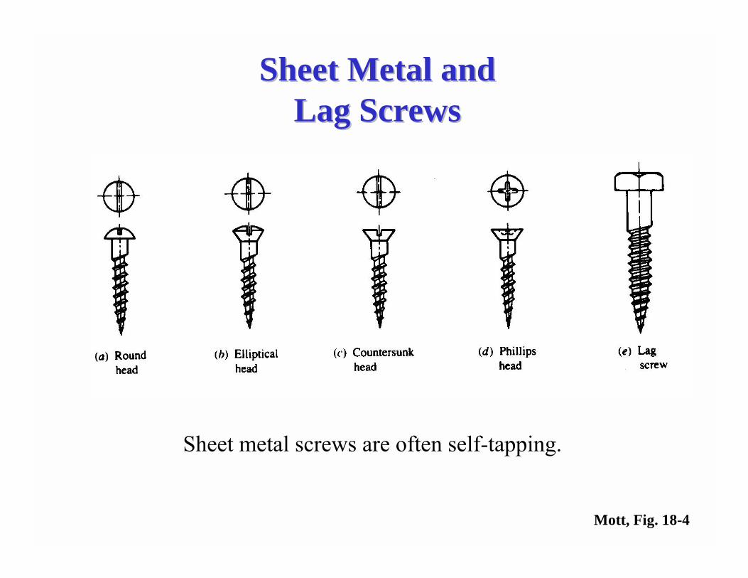
Sheet Metal and Sheet Metal and Lag ScrewsLag Screws
Sheet metal screws are often self-tapping.
Mott, Fig. 18-4
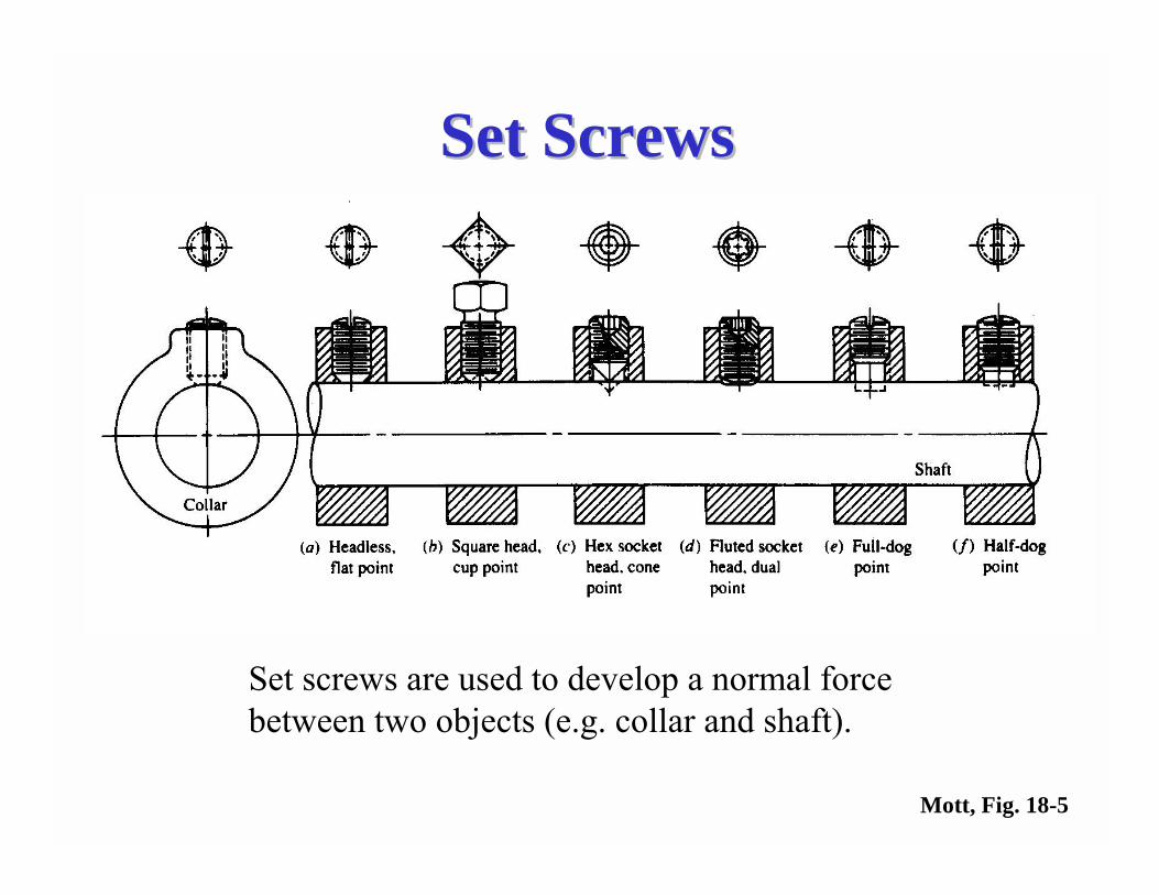
Set ScrewsSet Screws
Set screws are used to develop a normal force between two objects (e.g. collar and shaft).
Mott, Fig. 18-5
Thread StandardsThread Standards(Inch Series)(Inch Series)
American Standard B1.1American Standard B1.1--19491949
First American standard to cover the Unified Thread Series agreed upon by the United Kingdom, Canada, and the United States. Represents the basic American standard for fastener threads. Threads made to this standard are called �unified threads�.
ANSI B1.1ANSI B1.1--1989/ASME B1.11989/ASME B1.1--19891989
Revised standard that still incorporates much of the original standard.
Thread StandardsThread Standards(Metric Series)(Metric Series)
ANSI B1.13MANSI B1.13M--1983 (R1989)1983 (R1989)
Contains system of metric threads for general fastening purposes in mechanisms and structures. Fasteners made to this standard are often referred to as M-series.
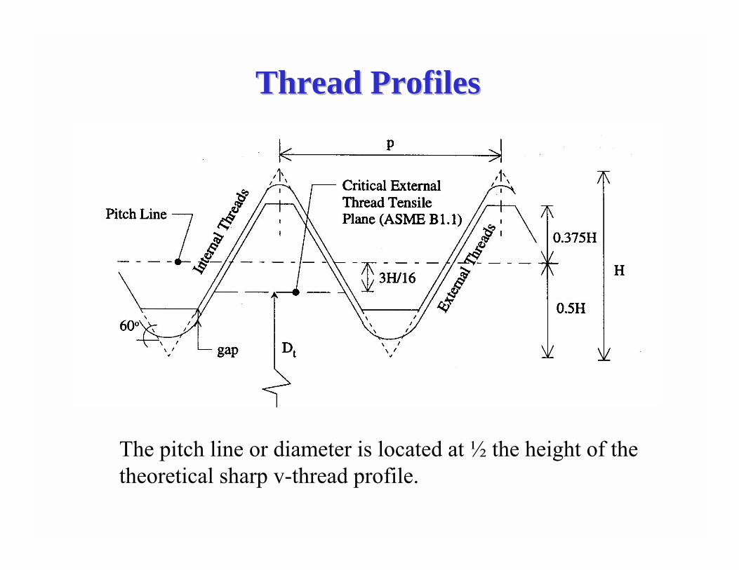
Thread ProfilesThread Profiles
The pitch line or diameter is located at ½ the height of the theoretical sharp v-thread profile.

Thread SeriesThread Series
Unified CoarseUnified Coarse--Thread Series (UNC or UNRC)Thread Series (UNC or UNRC)
Thread SeriesThread Series � groups of diameter-pitch combinations distinguished from each other by the number of threads per inch applied to a specific diameter.
Most commonly used in the bulk production of bolts, screws, nuts for general engineering applications.
Unified FineUnified Fine--Thread Series (UNF or UNRF)Thread Series (UNF or UNRF)Use when more threads per inch are required (i.e. where are short length of engagement is available).
MM--SeriesSeriesMetric system of diameters, pitches, and tolerance/allowances.

Thread ClassesThread Classes
Thread ClassesThread Classes � Define the amount of tolerance and allowance associated with a particular thread.
Classes 1A, 2A, 3AClasses 1A, 2A, 3A � apply to external threads. Class 2A is the most commonly used.
Classes 1B, 2B, 3BClasses 1B, 2B, 3B � apply to internal threads. Class 2B is the most commonly used.

Thread DesignationsThread Designations(Inch Series)(Inch Series)
2A20UNC41 −−
Nominal Size
Threads per inch
Thread Series
Thread Class
External Thread
The following is an example of the standard method used to designate bolt and screw thread requirements on a drawing or in a specification.
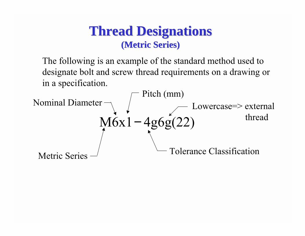
Thread DesignationsThread Designations(Metric Series)(Metric Series)
4g6g(22)M6x1−
The following is an example of the standard method used to designate bolt and screw thread requirements on a drawing or in a specification.
Metric Series
Nominal DiameterPitch (mm)
Tolerance Classification
Lowercase=> external thread
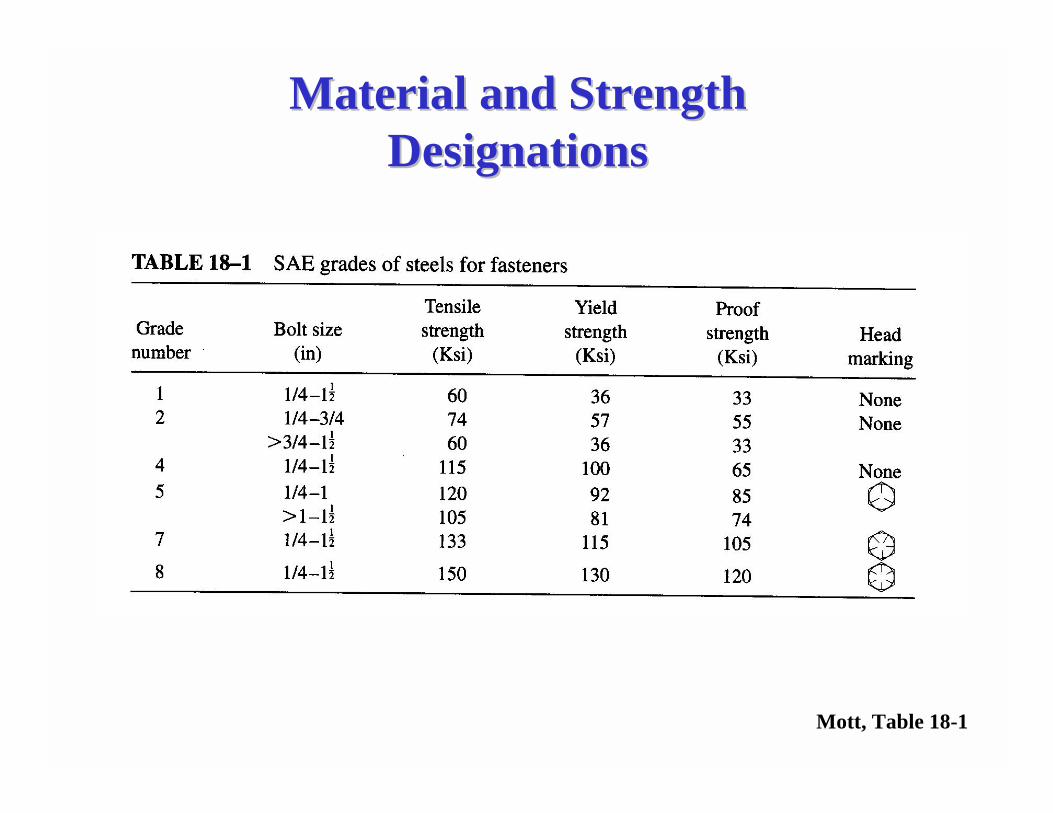
Material and Strength Material and Strength DesignationsDesignations
Mott, Table 18-1
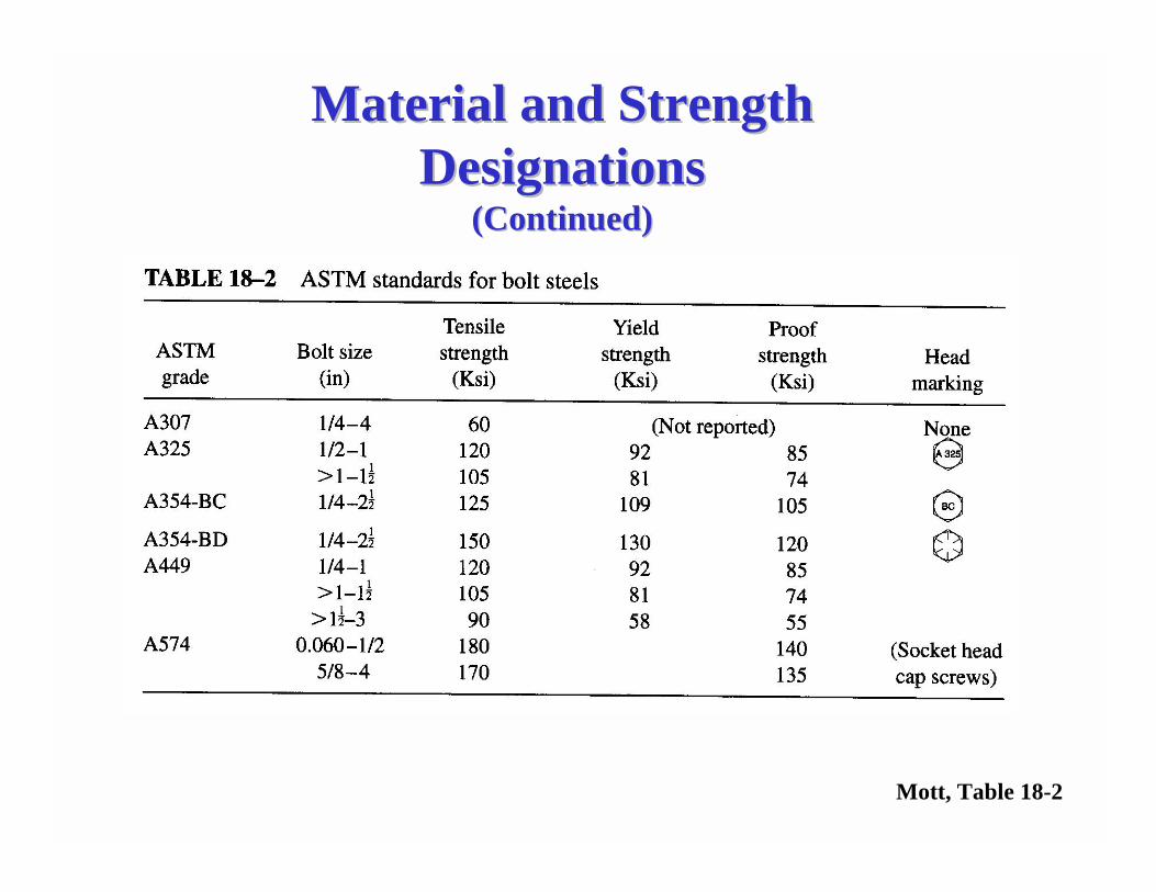
Material and Strength Material and Strength DesignationsDesignations
(Continued)(Continued)
Mott, Table 18-2

Material and Strength Material and Strength DesignationsDesignations
Mott, Table 18-3
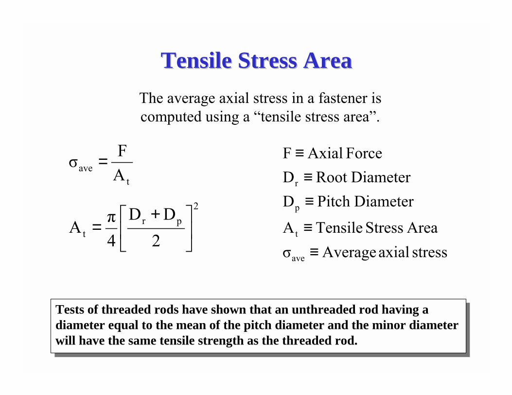
Tensile Stress AreaTensile Stress AreaThe average axial stress in a fastener is computed using a �tensile stress area�.
2pr
t 2DD
4πA �
�
���
� +=
tave A
Fσ =
stress axial AverageσArea Stress TensileA
DiameterPitch DDiameterRoot D
Force AxialF
ave
t
p
r
≡≡
≡≡
≡
Tests of threaded rods have shown that an unthreaded rod having a diameter equal to the mean of the pitch diameter and the minor diameter will have the same tensile strength as the threaded rod.

Tensile Stress AreaTensile Stress Area(Continued)(Continued)
( )°⋅=
��
���
� +−=
60tan2n1H
H163H
832dD bt
threads/inp1n threadofheight ltheoreticaH
bolt ofdiameter dplane criticalat diameter D
b
t
=≡≡≡≡
Matt Scolforo, Sverdrup Technology

Tensile Stress AreaTensile Stress Area(Continued)(Continued)
( )
( )
n1639dD
163
83
n60tandD
60tan2n1H
H163H
832dD
bt
bt
bt
−=
��
���
� +°−=
°⋅=
��
���
� +−=
2
bt
2tt
n0.9743d
4πA
D4πA
��
���
� −=
⋅=
This is the formula used by manufacturers of inch series fasteners to publish the tensile area in their catalogs.

Tensile Stress AreaTensile Stress Area(Continued)(Continued)
2
bt n0.9328d
4πA �
�
���
� −=
The following formula may be obtained in a similar manner for metric series threads.
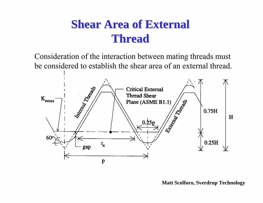
Shear Area of External Shear Area of External ThreadThread
Consideration of the interaction between mating threads must be considered to establish the shear area of an external thread.
Matt Scolforo, Sverdrup Technology

Shear Area of External ThreadsShear Area of External Threads(Continued)(Continued)
( )gap0.75H
0.5t30tan
ntKπA
e
emaxn,es,
−=°
⋅⋅⋅=
inchper threadsnplaneshear criticalat threadexternal of thicknesst
threadinternal ofdiameter minor maximumK threadexternal of areashear A
e
maxn,
es,
≡≡
≡≡

Shear Area of External Shear Area of External ThreadsThreads(Continued)(Continued)
( )
( )
( ) ���
����
�−°⋅=
=°=
−=°
⋅⋅⋅=
gap2n
30.7530tan2t
2n360tan
2n1H
gap0.75H0.5t30tan
ntKπA
e
e
emaxn,s,e
( )maxn,mins,e
mins,maxn,e
mins,maxn,
KE3
12n1t
E2n
321K
21
2n3
43
312t
E2n
321K
21gap
−+=
���
�
���
�
���
�
�−+−⋅=
���
�
�−+=
The gap equation is based on tolerance data.
Es,min=minimum pitch diameter of the external thread
Shear Area of External Shear Area of External ThreadsThreads(Continued)(Continued)
( )��
���
� −+⋅⋅⋅= maxn,mins,maxn,es, KE3
12n1KnπA
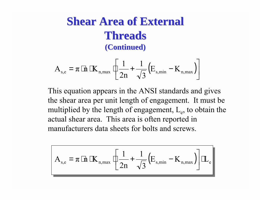
This equation appears in the ANSI standards and gives the shear area per unit length of engagement. It must be multiplied by the length of engagement, Le, to obtain the actual shear area. This area is often reported in manufacturers data sheets for bolts and screws.
( ) emaxn,mins,maxn,es, LKE3
12n1KnπA ⋅�
�
���
� −+⋅⋅⋅=
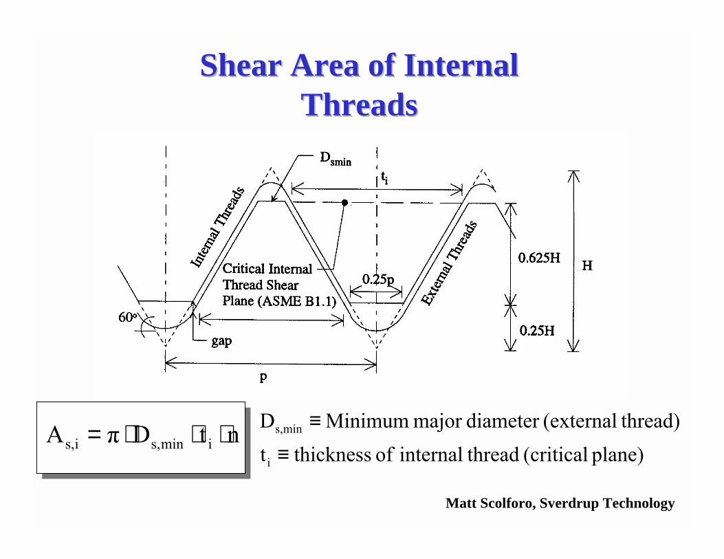
Shear Area of Internal Shear Area of Internal ThreadsThreads
ntDπA imins,is, ⋅⋅⋅=plane) (critical threadinternal of thicknesst
thread)(externaldiameter major MinimumD
i
mins,
≡≡
Matt Scolforo, Sverdrup Technology
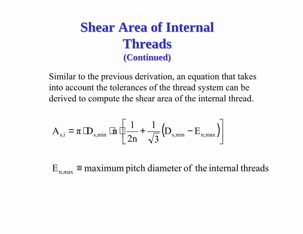
Shear Area of Internal Shear Area of Internal ThreadsThreads(Continued)(Continued)
( )
threadsinternal theofdiameter pitch maximumE
ED3
12n1nDπA
maxn,
maxn,mins,mins,is,
≡
��
���
� −+⋅⋅⋅=
Similar to the previous derivation, an equation that takes into account the tolerances of the thread system can be derived to compute the shear area of the internal thread.

Length of EngagementLength of Engagement(Equal Strength Materials)(Equal Strength Materials)
If the internal thread and external thread material have the same strength, then
t
maxt A
FS =eis,
maxt LA
F0.5S⋅
=
is,
te
eis,tttmax
A2AL
LA0.5SASF
=
==
Tensile StrengthTensile Strength(External Thread)(External Thread)
Shear StrengthShear Strength(Internal Thread)(Internal Thread)

Length of EngagementLength of Engagement(Unequal Strength Materials)(Unequal Strength Materials)
If the internal thread and external thread do not have the same material, then
t
maxet, A
FS =eis,
maxit, LA
F0.5S⋅
=
it,is,
et,te
eis,it,tet,max
SAS2A
L
LA0.5SASF
⋅⋅
=
==
Tensile StrengthTensile Strength(External Thread)(External Thread)
Shear StrengthShear Strength(Internal Thread)(Internal Thread)
Bolt/Nut Design PhilosophyBolt/Nut Design Philosophy
ANSI standard bolts and nuts of equal grades are designed to have the bolt fail before the threads in the nut are stripped.
The engineer designing a machine element is responsible for determining how something should fail taking into account the safety of the operators and public. Length of engagement is an important consideration in designing machine elements with machine screws.
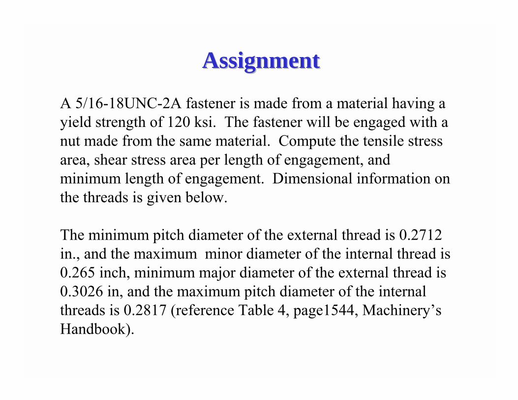
AssignmentAssignment
A 5/16-18UNC-2A fastener is made from a material having a yield strength of 120 ksi. The fastener will be engaged with a nut made from the same material. Compute the tensile stress area, shear stress area per length of engagement, and minimum length of engagement. Dimensional information on the threads is given below.
The minimum pitch diameter of the external thread is 0.2712 in., and the maximum minor diameter of the internal thread is 0.265 inch, minimum major diameter of the external thread is 0.3026 in, and the maximum pitch diameter of the internal threads is 0.2817 (reference Table 4, page1544, Machinery�s Handbook).