
Mechanical Failure Mode Analysis · NORSOK S-002 7. NORSOK S-005 8. DNV-OS-E402 2004 9. CE RoHS...
107
Open Publication OPEN SAFETY EQUIPMENT LTD FAMILY OF REBREATHERS FAILURE MODE, EFFECT AND CRITICALITY ANALYSIS VOLUME 4: Mechanical Failure Mode Analysis DOCUMENT NUMBER: [Filename] FMECA_OR_V4_180821.doc CONTRIBUTORS: Dr. Alex Deas, Dr. Bob Davidov, Marat Evtukov, Alexei Bogatchov, Dr Vladimir Komarov, Dr Oleg Zabgreblenny, Dr Alexander Kudriashov, and client review teams. DEPARTMENT: Engineering LAST REVISED: 21 st August 2018 REVISION: B13 APPROVALS ____/AD/_____________________ Project Manager _____21st Aug 2018_____ Date ____/KB/________________________ Quality Officer _____21 st Aug 2018_____ Date Controlled Document Classified Document DO NOT COPY. Copyright © 2006, 2007, 2008, 2009, 2010, 2014, 2015, 2018 Deep Life Group All patents, patent applications, design and topographical rights reserved. No circuit may be reproduced without a licence for the topographical rights contained therein from Open Safety Equipment Ltd, a Deep Life Group company. This document does not constitute a licence to use any patent, patent application or topographical right of Deep Life Group. FMECA_OR_V4_180821.doc Rev B13 Page 1 of 107
Transcript of Mechanical Failure Mode Analysis · NORSOK S-002 7. NORSOK S-005 8. DNV-OS-E402 2004 9. CE RoHS...
Open Publication
OPEN SAFETY EQUIPMENT LTDFAMILY OF REBREATHERS
FAILURE MODE, EFFECT ANDCRITICALITY ANALYSIS VOLUME 4:
Mechanical Failure Mode AnalysisDOCUMENT
NUMBER:[Filename]
FMECA_OR_V4_180821.doc
CONTRIBUTORS: Dr. Alex Deas, Dr. Bob Davidov, Marat Evtukov, AlexeiBogatchov, Dr Vladimir Komarov, Dr Oleg Zabgreblenny,Dr Alexander Kudriashov, and client review teams.
DEPARTMENT: Engineering
LAST REVISED: 21st August 2018
REVISION: B13
APPROVALS
____/AD/_____________________Project Manager
_____21st Aug 2018_____Date
____/KB/________________________Quality Officer
_____21st Aug 2018_____Date
ControlledDocument
Classified Document DO NOT COPY.
Copyright © 2006, 2007, 2008, 2009, 2010, 2014, 2015, 2018 Deep Life Group
All patents, patent applications, design and topographical rights reserved. No circuit may bereproduced without a licence for the topographical rights contained therein from Open SafetyEquipment Ltd, a Deep Life Group company. This document does not constitute a licence touse any patent, patent application or topographical right of Deep Life Group.
FMECA_OR_V4_180821.doc Rev B13 Page 1 of 107
Open Publication
Revision History
Revision Date Description
A 11P
thP Nov 2006 Document assembled from other files
B6 14P
thP Feb 2009 3P
rdP Jan 2007Update based on test results. Clarified
Method. B2: Results from HAZOP reviews held in Jan07 added 16P
thP Feb 2007. B3 is addition of XFig 4-32X only in Feb
2007. B4 on 28 P
thP May added consideration of water
dumps and review of all previous actions, followingmanned trials. B5 on 26 P
thP Oct 2008 updated water dump
decision based on feedback from training managers. B6on 14P
thP Feb 2009, updating ALVBOV
B7 22th May 2009 Intermediate pressure over-pressure effects consideredin more detail, and section on Over-pressure valvesadded.
B8 23rd Aug 2009 Updated with ALVBOV seal failures, manual oxygendosing unit failures, and flapper web failures.
B9 5th Dec 2009 Material MSDS references updated
B10
B11
31st Jul 2010
21st Aug 2014
Sections 4.4, 4.10, 4.16 and 4.27 Updated. Sections4.17 and 4.30 added. Clarification of flapper valvereverse pressure requirement.
Added further detail to flapper valves and also new waterdump design, Sections 4.10 and 4.14. Changes in 2013Version of EN 14143 considered: no change found to berequired other than as minor update to Section 2.
B12 21st Aug 2015 PFD-HUD images added. Further detail on hosesadded.
B13 21st Aug 2018 Detail of battery test by SIRA for ATEX compatibilityadded (for PFD-HUD) and all eCCRs models.
FMECA_OR_V4_180821.doc Rev B13 Page 2 of 107

Open Publication
Table of Contents
1 PURPOSE AND SCOPE................................................................................................8
2 STANDARDS.................................................................................................................8
3 DESIGN OVERVIEW......................................................................................................8
3.1 Surface Supplied eSCR/eCCR..........................................................................................................10
3.2 Multi-role professional Rebreather, Incursion-MIL models..........................................................11
3.3 Sports Pure O2 Rebreather and iCCR.............................................................................................14
4 FAILURE MODE ANALYSIS.......................................................................................17
4.1 Cylinders............................................................................................................................................17
4.2 Cylinder Valves..................................................................................................................................174.2.1 Design Decision Review...............................................................................................................174.2.2 Risk Assessment...........................................................................................................................174.2.3 Failure Mode Analysis..................................................................................................................17
4.3 First Stage Regulators.......................................................................................................................184.3.1 Design Decision Review...............................................................................................................184.3.2 Risk Assessment...........................................................................................................................184.3.3 Failure Mode Analysis..................................................................................................................18
4.4 Intermediate Pressure Relief Valves................................................................................................184.4.1 Design Decision Review...............................................................................................................184.4.2 Risk Assessment...........................................................................................................................194.4.3 Failure Mode Analysis..................................................................................................................19
4.5 Pressure sensors.................................................................................................................................194.5.1 Design Decision Review...............................................................................................................194.5.2 Risk Assessment...........................................................................................................................204.5.3 Failure Mode Analysis..................................................................................................................21
4.6 High pressure hoses...........................................................................................................................21
4.7 Rigid Medium Pressure hoses...........................................................................................................21
4.8 Flexible Medium Pressure hoses.......................................................................................................214.8.1 Marking.........................................................................................................................................224.8.2 Kink test.......................................................................................................................................234.8.3 MSDS...........................................................................................................................................234.8.4 Kink test........................................................................................................................................234.8.5 Test Pressures................................................................................................................................234.8.6 Failure Mode.................................................................................................................................23
4.9 Breathing Hose Ports.........................................................................................................................264.9.1 Design Decision Review...............................................................................................................264.9.2 Risk Assessment...........................................................................................................................26
FMECA_OR_V4_180821.doc Rev B13 Page 3 of 107
Open Publication
4.9.3 Failure Mode Analysis..................................................................................................................28
4.10 Water Dumps...................................................................................................................................294.10.1 Design Decision Review.............................................................................................................294.10.2 Risk Assessment..........................................................................................................................294.10.3 Failure Mode Analysis................................................................................................................30
4.11 Breathing Hoses...............................................................................................................................324.11.1 Design Decision Review.............................................................................................................32
4.11.1.1 Flexible Only versus Flex with Rigid Sections.....................................................................324.11.1.2 Material................................................................................................................................324.11.1.3 Manufacturing Method.........................................................................................................324.11.1.4 Overall Assessment..............................................................................................................33
4.11.2 Compliance.................................................................................................................................334.11.3 Risk Assessment..........................................................................................................................364.11.4 Failure Mode Analysis................................................................................................................374.11.5 Training Requirement.................................................................................................................38
4.12 Breathing Hose Connections...........................................................................................................384.12.1 Design Decision Review.............................................................................................................384.12.2 Risk Assessment..........................................................................................................................404.12.3 Failure Mode Analysis................................................................................................................40
4.13 O-rings and X-rings.........................................................................................................................404.13.1 Design Decision Review.............................................................................................................414.13.2 Risk Analysis..............................................................................................................................414.13.3 Failure Mode Analysis................................................................................................................424.13.4 Training Requirement.................................................................................................................43
4.14 Flapper valves..................................................................................................................................434.14.1 Design Decision Review.............................................................................................................434.14.2 Compliance.................................................................................................................................474.14.3 Risk Analysis..............................................................................................................................484.14.4 Failure Mode Analysis................................................................................................................49
4.15 Mouthpiece: plain DSV version......................................................................................................514.15.1 Design Decision Review.............................................................................................................514.15.2 Compliance.................................................................................................................................534.15.3 Risk Assessment..........................................................................................................................534.15.4 Failure Mode Analysis................................................................................................................53
4.16 Mouthpiece: ALVBOV Version......................................................................................................544.16.1 Design Decision Review.............................................................................................................544.16.2 Risk Assessment..........................................................................................................................564.16.3 Failure Mode Analysis................................................................................................................59
4.16.3.1 Failure to operate..................................................................................................................594.16.3.2 Failure to actuate..................................................................................................................594.16.3.3 Free Flow..............................................................................................................................594.16.3.4 Seal failure modes................................................................................................................604.16.3.5 Connector failure modes.......................................................................................................61
4.17 Automatic Loop Volume device (ALV)..........................................................................................614.17.1 Design Decision Review.............................................................................................................614.17.2 Risk Assessment..........................................................................................................................624.17.3 Failure Mode Analysis................................................................................................................62
FMECA_OR_V4_180821.doc Rev B13 Page 4 of 107
Open Publication
4.18 Hose weights.....................................................................................................................................644.18.1 Design Decision Review.............................................................................................................644.18.2 Risk Assessment..........................................................................................................................644.18.3 Failure Mode Analysis................................................................................................................65
4.19 Peripheral Field Display (PFD)......................................................................................................654.19.1 Design Decision Review.............................................................................................................654.19.2 Risk Analysis..............................................................................................................................654.19.3 Failure Mode Analysis................................................................................................................66
4.20 Counterlungs....................................................................................................................................664.20.1 Design Decision Review.............................................................................................................664.20.2 Compliance.................................................................................................................................704.20.3 Risk Analysis..............................................................................................................................704.20.4 Failure Mode Analysis................................................................................................................71
4.21 Counterlung Covers.........................................................................................................................714.21.1 Design Decision Review.............................................................................................................714.21.2 Risk Analysis..............................................................................................................................724.21.3 Failure Mode Analysis................................................................................................................72
4.22 Scrubber Housing............................................................................................................................724.22.1 Design Decision Review.............................................................................................................724.22.2 Risk Assessment..........................................................................................................................744.22.3 Failure Mode Analysis................................................................................................................75
4.23 Scrubber attachment.......................................................................................................................754.23.1 Design Decision Review.............................................................................................................754.23.2 Risk Assessment .........................................................................................................................754.23.3 Failure Modes.............................................................................................................................75
4.24 Scrubber Seal...................................................................................................................................764.24.1 Design Decision Review.............................................................................................................764.24.2 Risk Assessment..........................................................................................................................764.24.3 Failure Mode Analysis................................................................................................................76
4.25 Scrubber Housing Seal....................................................................................................................784.25.1 Design Decision Review.............................................................................................................784.25.2 Risk Assessment..........................................................................................................................784.25.3 Failure Mode Analysis................................................................................................................78
4.26 Flow Cones.......................................................................................................................................784.26.1 Design Decision Review.............................................................................................................784.26.2 Risk Assessment..........................................................................................................................784.26.3 Failure Mode Analysis................................................................................................................79
4.27 Electronic Gas Injector...................................................................................................................794.27.1 Design Decision Review.............................................................................................................794.27.2 Risk Assessment..........................................................................................................................794.27.3 Failure Mode Analysis................................................................................................................794.27.4 Reliability Testing.......................................................................................................................804.27.5 Leakage and Fail Open Risk Mitigation......................................................................................804.27.6 Contamination Risk Mitigation...................................................................................................81
4.27.6.1 Inlet Protection.....................................................................................................................824.27.6.2 Back Flow Protection...........................................................................................................82
FMECA_OR_V4_180821.doc Rev B13 Page 5 of 107
Open Publication
4.28 Passive Addition and Manual Oxygen Dosing valve.....................................................................834.28.1 Design Decision Review.............................................................................................................834.28.2 Risk Assessment..........................................................................................................................844.28.3 Failure Mode Analysis................................................................................................................85
4.29 Battery Housings..............................................................................................................................864.29.1 Design Decision Review.............................................................................................................864.29.2 Compliance.................................................................................................................................864.29.3 Risk Assessment..........................................................................................................................864.29.4 Failure Mode Analysis................................................................................................................87
4.30 Oxygen Cells and Cell Holders.......................................................................................................874.30.1 Design Decision Review.............................................................................................................874.30.2 Risk Assessment..........................................................................................................................874.30.3 Failure Mode Analysis................................................................................................................88
4.31 Electronics Chamber.......................................................................................................................884.31.1 Design Decision Review.............................................................................................................884.31.2 Risk Assessment..........................................................................................................................894.31.3 Failure Mode Analysis................................................................................................................89
4.32 Connector penetrators.....................................................................................................................894.32.1 Design Decision Review.............................................................................................................894.32.2 Risk Assessment..........................................................................................................................894.32.3 Failure Mode Analysis................................................................................................................90
4.33 Connector reliability........................................................................................................................904.33.1 Design Decision Review.............................................................................................................904.33.2 Risk Assessment..........................................................................................................................924.33.3 Failure Mode Analysis................................................................................................................93
4.34 Gas Port Mechanical Reliability.....................................................................................................934.34.1 Design Decision Review.............................................................................................................934.34.2 Risk Assessment..........................................................................................................................934.34.3 Failure Mode Analysis................................................................................................................94
4.35 Scrubber Stick..................................................................................................................................944.35.1 Design Decision Review.............................................................................................................944.35.2 Risk Assessment..........................................................................................................................944.35.3 Failure Mode Analysis................................................................................................................95
4.36 CO2 sensor and window..................................................................................................................954.36.1 Design Decision Review.............................................................................................................954.36.2 Risk Assessment..........................................................................................................................964.36.3 Failure Mode Analysis................................................................................................................96
4.37 Sensor Bell Membrane....................................................................................................................974.37.1 Design Decision Review.............................................................................................................974.37.2 Risk Assessment..........................................................................................................................974.37.3 Failure Mode Analysis................................................................................................................97
4.38 Scrubber Cartridge.........................................................................................................................984.38.1 Design Decision Review.............................................................................................................984.38.2 Risk Assessment..........................................................................................................................984.38.3 Failure Mode Analysis................................................................................................................99
4.39 Breathing Gas Heating....................................................................................................................99
FMECA_OR_V4_180821.doc Rev B13 Page 6 of 107

Open Publication
4.39.1 Design Decision Review.............................................................................................................994.39.2 Risk Assessment..........................................................................................................................994.39.3 Failure Mode Analysis..............................................................................................................100
4.40 Gas Circuit in Umbilical Supplied Configuration.......................................................................1004.40.1 Design Decision Review...........................................................................................................1004.40.2 Risk Analysis............................................................................................................................1044.40.3 Failure Mode Analysis..............................................................................................................105
4.41 Gas Flow of SCUBA configurations.............................................................................................106
5 CONFIRMATION OF CLOSURE ON SAFETY ACTIONS........................................1065.1.1 Failure Mode Analysis................................................................................................................106
FMECA_OR_V4_180821.doc Rev B13 Page 7 of 107
Open Publication
1 PURPOSE AND SCOPEThis is Volume 4 of the FMECA of the safety case for the Open Safety Equipment Ltdrebreathers, Project ORECCR1.
This document covers the safety, risk and failure analysis of the mechanical components inthe rebreather on a bottom up basis, that is, considering the mechanical system componentby component.
The rebreather can be configured as single or dual scrubber, for surface supplied or selfcontained applications.
All tests carried out in this report, were performed by the Baltic Assessment Institute, anindependent legal entity from Deep Life Ltd and Open Safety Equipent Ltd.
2 STANDARDS
Many standards and advisory groups have considered the issues of rebreather safety andissued documents setting minimum requirements needed from the system to address theissues they identified. The relevant documents identified by the Review Team are:
1. EN14143:2003 and 2013
2. EN13555:2008
3. EN61508 Parts 1 to 3
4. NORSOK U-100:2006
5. NORSOK U-101:1999
6. NORSOK S-002
7. NORSOK S-005
8. DNV-OS-E402 2004
9. CE RoHS Directive
10. CE EMC Directive
11. CE Low Voltage Directive
12. CE Machinery Directives
13. IMCA AODC 035
The design has been verified against the relevant sections of each one of the abovestandards or advisory documents, with 5 units of each type as required by NORSOK U101.
Reference is made to these standards in this FMECA to ensure proper consideration hasbeen given to failure modes and minimum performance targets.
Compliance matrices have been produced for each of these standards, with supporting testdata, of which this is a part (for NORSOK U101, EN61508 and EN14143).
This document does not replace the clause by clause compliance verification documents.
3 DESIGN OVERVIEW
The project forms a technology base that is realised in several formats, specific to theapplication.
The four formats considered by this review are:
• Surface supplied umbilical diver’s eCCR / eSCR: dual scrubber, with umbilicalcomms, video, lighting, heating and real-time monitoring topside. (Model UmbilicalDiver’s eCCR)
• Multi-role professional rebreather: single scrubber and through water comms SCUBArebreather (Model Incursion, front or back mountable, or back mount only)configurable to operate in manual O2, SCR, switched mode, and eCCR modes.
FMECA_OR_V4_180821.doc Rev B11 Page 8 of 107
Open Publication
• sports iCCR: single scrubber with monitoring (Model Apocalpyse Type IV iCCR)
• sports O2-CCR: single scrubber (Model Apocalpyse Type IV O2-CCR)
Each of these configuratons are described separately in detail by Green Book engineeringdescriptions. These documents describe the design and in their realisation, in accordancewith QP-05 and QP-20 in the ISO 9001 quality system operated by Deep Life Ltd.
No attempt will be made here to cover the detail that is in the Green Books, other than ageneral overview as each component is considered and the following general description toenable the reader to follow the points arising from the review. Conversely, there is inevitablysome repetition of material from the Green Books in this review, because Failure ModeAnalysis preceded design work and continued in parallel with the design, as required byQuality Process QP-20.
The realisations of all major subassemblies have been tested according to a formal TestPlan and the results are described in respective Design Verification Reports.
FMECA_OR_V4_180821.doc Rev B11 Page 9 of 107
Open Publication
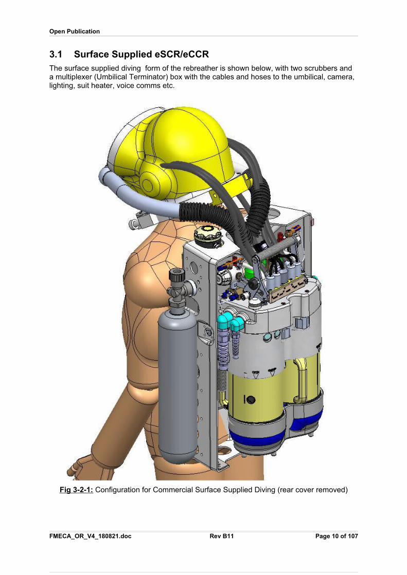
3.1 Surface Supplied eSCR/eCCRThe surface supplied diving form of the rebreather is shown below, with two scrubbers and a multiplexer (Umbilical Terminator) box with the cables and hoses to the umbilical, camera, lighting, suit heater, voice comms etc.
Fig 3 - 2-1: Configuration for Commercial Surface Supplied Diving (rear cover removed)
FMECA_OR_V4_180821.doc Rev B11 Page 10 of 107
Open Publication
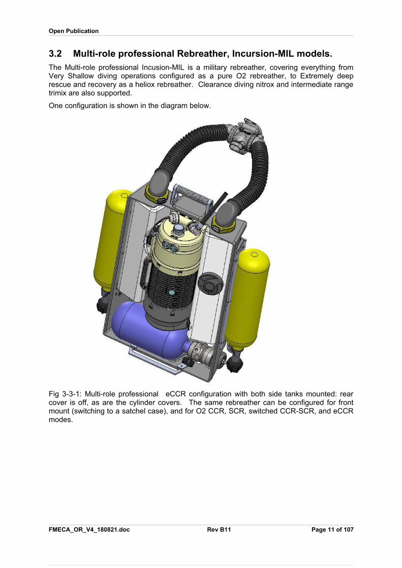
3.2 Multi-role professional Rebreather, Incursion-MIL models.The Multi-role professional Incusion-MIL is a military rebreather, covering everything fromVery Shallow diving operations configured as a pure O2 rebreather, to Extremely deeprescue and recovery as a heliox rebreather. Clearance diving nitrox and intermediate rangetrimix are also supported.
One configuration is shown in the diagram below.
Fig 3-3-1: Multi-role professional eCCR configuration with both side tanks mounted: rearcover is off, as are the cylinder covers. The same rebreather can be configured for frontmount (switching to a satchel case), and for O2 CCR, SCR, switched CCR-SCR, and eCCRmodes.
FMECA_OR_V4_180821.doc Rev B11 Page 11 of 107
Open Publication
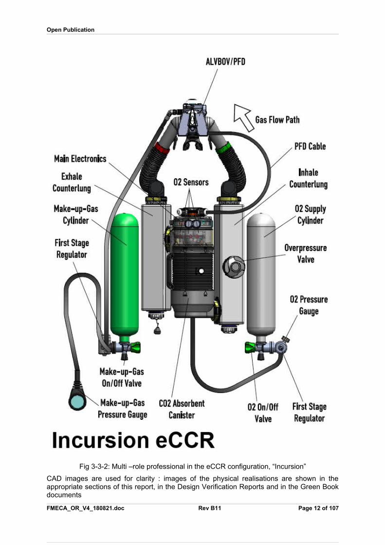
Fig 3-3-2: Multi –role professional in the eCCR configuration, “Incursion”
CAD images are used for clarity : images of the physical realisations are shown in theappropriate sections of this report, in the Design Verification Reports and in the Green Bookdocuments
FMECA_OR_V4_180821.doc Rev B11 Page 12 of 107
Open Publication
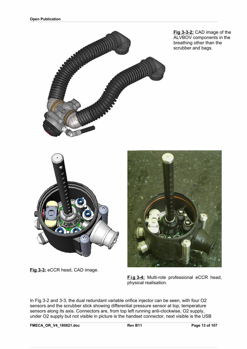
Fig 3 - 3-2: CAD image of theALVBOV components in the breathing other than the scrubber and bags.
In Fig 3-2 and 3-3, the dual redundant variable orifice injector can be seen, with four O2 sensors and the scrubber stick showing differential pressure sensor at top, temperature sensors along its axis. Connectors are, from top left running anti-clockwise, O2 supply, under O2 supply but not visible in picture is the handset connector, next visible is the USB
FMECA_OR_V4_180821.doc Rev B11 Page 13 of 107
Fig 3 - 3 : eCCR head, CAD image.
Fig 3 - 4 : Multi-role professional eCCR head,physical realisation.
Open Publication
and charging PFD, battery housing 1, hose port to inhale counterlung, battery housing 2. PFD port can just be seen under hose port. .
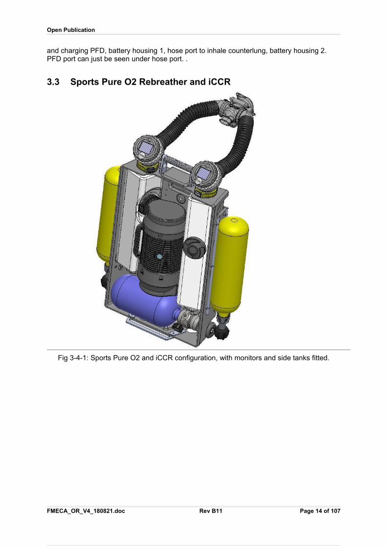
3.3 Sports Pure O2 Rebreather and iCCR
Fig 3-4-1: Sports Pure O2 and iCCR configuration, with monitors and side tanks fitted.
FMECA_OR_V4_180821.doc Rev B11 Page 14 of 107
Open Publication
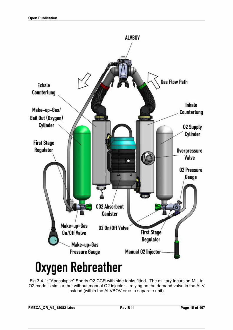
Fig 3-4-1: “Apocalypse” Sports O2-CCR with side tanks fitted. The military Incursion-MIL inO2 mode is similar, but without manual O2 injector – relying on the demand valve in the ALV
instead (within the ALVBOV or as a separate unit).
FMECA_OR_V4_180821.doc Rev B11 Page 15 of 107
Open Publication
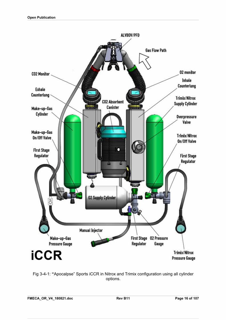
Fig 3-4-1: “Apocalpse” Sports iCCR in Nitrox and Trimix configuration using all cylinderoptions.
FMECA_OR_V4_180821.doc Rev B11 Page 16 of 107
Open Publication
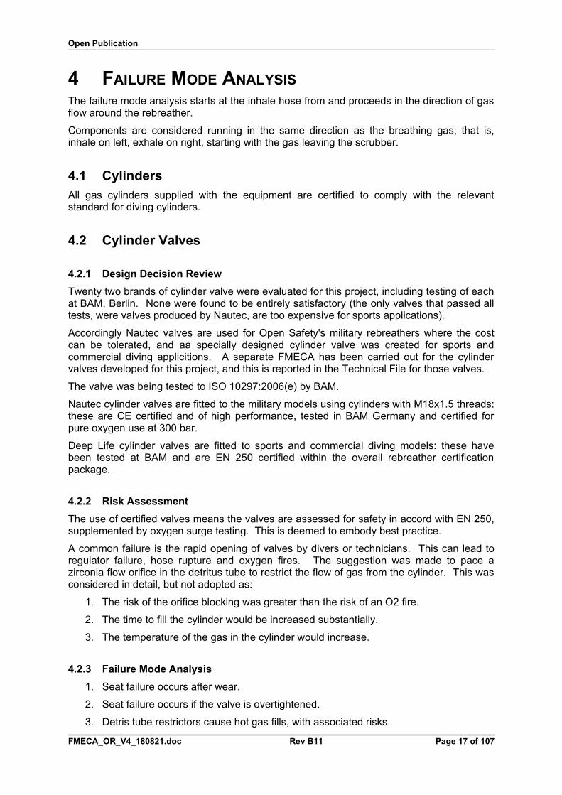
4 FAILURE MODE ANALYSIS
The failure mode analysis starts at the inhale hose from and proceeds in the direction of gasflow around the rebreather.
Components are considered running in the same direction as the breathing gas; that is,inhale on left, exhale on right, starting with the gas leaving the scrubber.
4.1 CylindersAll gas cylinders supplied with the equipment are certified to comply with the relevantstandard for diving cylinders.
4.2 Cylinder Valves
4.2.1 Design Decision Review
Twenty two brands of cylinder valve were evaluated for this project, including testing of eachat BAM, Berlin. None were found to be entirely satisfactory (the only valves that passed alltests, were valves produced by Nautec, are too expensive for sports applications).
Accordingly Nautec valves are used for Open Safety's military rebreathers where the costcan be tolerated, and aa specially designed cylinder valve was created for sports andcommercial diving applicitions. A separate FMECA has been carried out for the cylindervalves developed for this project, and this is reported in the Technical File for those valves.
The valve was being tested to ISO 10297:2006(e) by BAM.
Nautec cylinder valves are fitted to the military models using cylinders with M18x1.5 threads:these are CE certified and of high performance, tested in BAM Germany and certified forpure oxygen use at 300 bar.
Deep Life cylinder valves are fitted to sports and commercial diving models: these havebeen tested at BAM and are EN 250 certified within the overall rebreather certificationpackage.
4.2.2 Risk Assessment
The use of certified valves means the valves are assessed for safety in accord with EN 250,supplemented by oxygen surge testing. This is deemed to embody best practice.
A common failure is the rapid opening of valves by divers or technicians. This can lead toregulator failure, hose rupture and oxygen fires. The suggestion was made to pace azirconia flow orifice in the detritus tube to restrict the flow of gas from the cylinder. This wasconsidered in detail, but not adopted as:
1. The risk of the orifice blocking was greater than the risk of an O2 fire.
2. The time to fill the cylinder would be increased substantially.
3. The temperature of the gas in the cylinder would increase.
4.2.3 Failure Mode Analysis
1. Seat failure occurs after wear.
2. Seat failure occurs if the valve is overtightened.
3. Detris tube restrictors cause hot gas fills, with associated risks.
FMECA_OR_V4_180821.doc Rev B11 Page 17 of 107
Open Publication
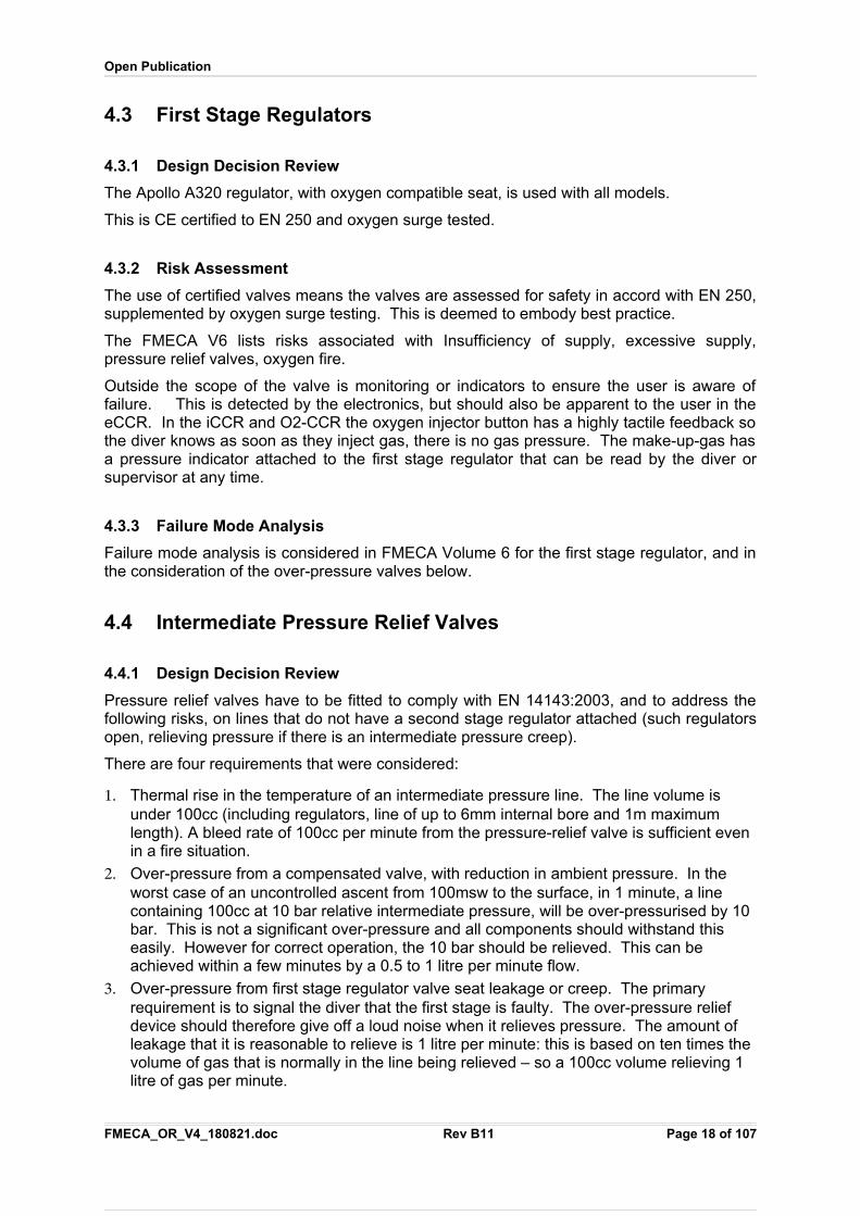
4.3 First Stage Regulators
4.3.1 Design Decision Review
The Apollo A320 regulator, with oxygen compatible seat, is used with all models.
This is CE certified to EN 250 and oxygen surge tested.
4.3.2 Risk Assessment
The use of certified valves means the valves are assessed for safety in accord with EN 250,supplemented by oxygen surge testing. This is deemed to embody best practice.
The FMECA V6 lists risks associated with Insufficiency of supply, excessive supply,pressure relief valves, oxygen fire.
Outside the scope of the valve is monitoring or indicators to ensure the user is aware offailure. This is detected by the electronics, but should also be apparent to the user in theeCCR. In the iCCR and O2-CCR the oxygen injector button has a highly tactile feedback sothe diver knows as soon as they inject gas, there is no gas pressure. The make-up-gas hasa pressure indicator attached to the first stage regulator that can be read by the diver orsupervisor at any time.
4.3.3 Failure Mode Analysis
Failure mode analysis is considered in FMECA Volume 6 for the first stage regulator, and inthe consideration of the over-pressure valves below.
4.4 Intermediate Pressure Relief Valves
4.4.1 Design Decision Review
Pressure relief valves have to be fitted to comply with EN 14143:2003, and to address thefollowing risks, on lines that do not have a second stage regulator attached (such regulatorsopen, relieving pressure if there is an intermediate pressure creep).
There are four requirements that were considered:
1. Thermal rise in the temperature of an intermediate pressure line. The line volume is under 100cc (including regulators, line of up to 6mm internal bore and 1m maximum length). A bleed rate of 100cc per minute from the pressure-relief valve is sufficient even in a fire situation.
2. Over-pressure from a compensated valve, with reduction in ambient pressure. In the worst case of an uncontrolled ascent from 100msw to the surface, in 1 minute, a line containing 100cc at 10 bar relative intermediate pressure, will be over-pressurised by 10 bar. This is not a significant over-pressure and all components should withstand this easily. However for correct operation, the 10 bar should be relieved. This can be achieved within a few minutes by a 0.5 to 1 litre per minute flow.
3. Over-pressure from first stage regulator valve seat leakage or creep. The primary requirement is to signal the diver that the first stage is faulty. The over-pressure relief device should therefore give off a loud noise when it relieves pressure. The amount of leakage that it is reasonable to relieve is 1 litre per minute: this is based on ten times the volume of gas that is normally in the line being relieved – so a 100cc volume relieving 1 litre of gas per minute.
FMECA_OR_V4_180821.doc Rev B11 Page 18 of 107
Open Publication
4. It is recognised that a large obstruction to the valve seat will cause a very large gas pulse which will likely burst the first stage diaphragm. Large obstructions should be avoided by fitting sintered filters on the inlets of first stage regulators, and where there is a possibility of a negative pressure (reverse pressure) being applied, then an outlet filter should be fitted to the first stage regulator or the system it connects to: this is mostly an issue for commercial diving gas manifolds.
Overall, the pressure relief device should relieve at least 1 litre per minute with a 50% over-pressure.
Extensive characterisation was carried out, reported in DV_OPRV_100720_A4.pdf
From June 2010, only one type of valve is used on all BOMs: ORT 6520 N1 Ed2.
4.4.2 Risk Assessment
The risks and their assessment are listed above.
The conclusion is the pressure relief valve should lift within a 50% increase of over-pressure,providing at least a 1 litre per minute flow rate, and a load noise.
The valves used lift within 2 bar of their over-pressure setting, providing a hundred times theminimum identified. The noise generated is so loud, the diver would turn off the cylinder if itwere in use and switch to another gas source.
The maximum flow rate of over 500 lpm presents the hazard of a rapid loss of all the gas inthe cylinder: a 2 litre cylinder containing 100 bar, will take 20 seconds to discharge. This ismitigated by the cylinder shut-off would normally be carried out by the diver within 10seconds.
4.4.3 Failure Mode Analysis
The failure mode is a loss of pressure, or a failure to prevent a rise in pressure.
Failure to open is unlikely to cause any significant safety issue, because the hose has aburst pressure more than twelve times the normal operating pressure, and there is a reliefmeans in the hose: either an open orifice, or a second stage regulator that will lift if there is agradual over-pressure.
A sudden over-pressure will blow the first stage diaphragm. This is mitigated by using filtersbefore and after the valves to prevent detritus getting underneath the valve seat
Failure where the valve leaks gas, is an unwanted failure and the dive would have to beaborted.
If a cylinder valve is opened too quickly, a hot and high pressure gas surge will occur. Thismay exceed the ability of any pressure relief valve to relieve the pressure due to its speed.A failure of a low pressure hose or of a regulator diaphragm may occur. Mitigation of thisfailure mode by use of flow orifices has been considered but rejected as it introduces twoother failure modes, with higher frequency than the failure being mitigated.
4.5 Pressure sensors
4.5.1 Design Decision Review
All self contained pressure gauges are CE certified. This does not consider saturation divinguse, so additional assessment was made in respect to helium environments.
The problem of helium ingress and damage to pressure sensors is well known.
FMECA_OR_V4_180821.doc Rev B11 Page 19 of 107
Open Publication
During the design process, each main type of pressure sensor was assessed for heliumdamage by exposure to pure helium at 141bar for a month. No piezo-electric or piezo-resistive sensor worked after such exposure: recovery times lasted days in some instances.This left strain gauges and capacitive pressure sensors as the basis for the present design.
Thelma Norway have reported a helium tolerant pressure sensor by filling the rear of thesensor with silicone oil, which is the pressurised such as by a screw with an O-ring. Themethod described by Thelma was reproduced and found not to be effective. The reasons forthe failure were explored and it was concluded that the mechanism by which helium invadesthe reference chamber of a pressure sensor is that it penetrates stress lines: that is,materials which are not under strain do not allow helium to pass through other than at anextremely low rate of diffusion, but materials under strain allow helium to pass four orders ofmagnitude or more, faster.
This phenomenon can be demonstrated using a helium party balloon. Such a balloon willlose enough helium to lose its buoyancy in air in around four days. If the balloon after beingfilled with helium is then sprayed with a thin layer of lacquer, it remains afloat for a month:the lacquer is under strain only from thermal expansion and contraction but the much thickerballoon rubber is under considerable strain.
This phenomenon means the Thelma sensor does not suffer helium ingress at the pressureat which the silicone oil is maintained at, but at other pressures, will suffer ingress.
To address this problem, the design takes the following approach:
1. Gas cylinder contents sensors are permitted to drift. The 8 bar drift caused by heliumat 140msw over a month is not significant if the sensor is considered as simplygenerally indicative of whether the bail out cylinder is full or not. The electronicsshould deduct 8 bar from the reading to ensure the operator is not misled: thecylinder overpressure of 8 bar does not present a significant safety hazard, as it isless than the effect of thermal expansion of the gas.
2. The depth sensor is a sealed sensor, in the silicone oil of the electronics chamber.Silicone oil is a liquid, so cannot be under strain. It equalises the pressure in theelectronics chamber with the ambient, meaning that the walls of the electronicschamber should not be under strain, therefore should not permeate helium. Thismeans the silicone oil should be free of helium and a sealed sensor in that oil shouldnot drift. This is confirmed by trials.
3. There is a differential sensor on the scrubber stick. This was changed from twoabsolute sensors to one differential capacitive sensor to overcome this helium driftissue.
Bourdon tube type pressure gauges are fitted to all gas supplies from dive tanks. In thecase of the SCUBA configuration of the equipment, the make-up-gas and bail-out gaugesare visible to the diver during the dive. There is no gauge on the oxygen supply visible to thediver, but it is highly visible during pre-dive checks. If there is an unexpected loss of oxygen,this is apparent to the diver using tactile feedback, whereupon bail out gas is supplied, andfor the iCCR and eCCRs there are additional electronic warnings.
4.5.2 Risk Assessment
The following risks have been identified in relation to the pressure sensors:
1. Complete failure. This is detected by the electronics, but should also be apparent tothe user.
2. Blockage of the diffusion sensor port.
FMECA_OR_V4_180821.doc Rev B11 Page 20 of 107
Open Publication
4.5.3 Failure Mode Analysis
The failure mode is a loss of pressure sensor data or resolution.
Small bourdon tube type gauges can cause the face plate to pop out during rapiddecompression after exposure to helium environments. The gauges are chosen so as not torelease any significant quantity of gas when this occurs.
4.6 High pressure hosesThere are no high pressure hoses other than to the pressure gauge, which is a CE certifiedgauge and hose supplied as a pair.
In the commercial rebreather there is high pressure pipework in Tungum pipe, with a 0.8mminternal bore and 3.8mm external diameter, that is rated to 600 bar, with a working pressureof 300 bar. Tungum is oxygen compatible.
4.7 Rigid Medium Pressure hosesIn the commercial rebreather and professional rebreather, the oxygen hose is pressurised asit feeds an electronic variable orifice injector: that hose is solid Tungum tube.
4.8 Flexible Medium Pressure hosesA variety of hoses are used within the dive industry for intermediate pressure gas:
Ref
Hose type and description Reliability.
Cost factor relative tothe lowest cost hose
1 1TE hose made by Conti to SAE 100R2 is used by the better dive equipment companies. It is not suitabile for oxygen charging from the information on:
http://www.contitech.de/pages/produk...ch-info_en.pdf
http://www.balflexusa.com/assets/fil...patibility.pdf
5 3
2 Miflex braided hoses. These have an excellent exterior appearance, but were found during tests in Open Safety to have high failure rates when used with pure oxygen. The certification data has not been released by the manufacturer, though is claimed to be EN 250.
The braiding makes the hose difficult to examine and to decontaminate. Failures occurred in testing with pure O2 in DLG laboratories.
3 6
3 Diesel fuel hose to SAE J844, J1131, J1394, or ASTM D471, 0624, 0638, D648, 0709, 0746, 0742, 02240. These are not intended for pneumatic use, nor for SCUBA diving, however they are used by some low cost dive equipment manufacturers. Theyare not suitable for intermediate pressure gas lines.
4 1
FMECA_OR_V4_180821.doc Rev B11 Page 21 of 107
Open Publication
4 Si Tech hose to EN 250. Elastomer hose, with aramid weave and reinforcement, rubberised outer layer. This has good flexibility and is available with a safe disconnect cover on international BC fittings.
7 11
5 OSEL PEX hose, see below. This hose has less flexibility than the Si Tech hose, and has a higher minimum bend radius. It is used by OSEL in commercial diving rebreathers.
8 11
6 OSEL TPU hose, see below.
This hose has less flexibility than the Si Tech hose, and has a higher minimum bend radius. It is used by OSEL in commercial diving rebreathers.
8 11
The reliability scale is determined from performance in tests in 100% O2 on a scale 0 to 10, with 10 being perfect.
A PEX and a TPU hose is used by OSEL for commercial diving applications, and Si Techhose is used for all other LP applications.
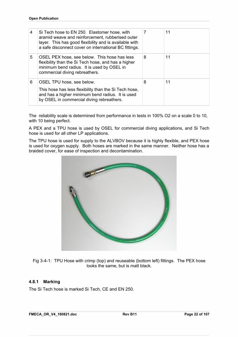
The TPU hose is used for supply to the ALVBOV because it is highly flexible, and PEX hoseis used for oxygen supply. Both hoses are marked in the same manner. Neither hose has abraided cover, for ease of inspection and decontamination.
Fig 3-4-1: TPU Hose with crimp (top) and reuseable (bottom left) fittings. The PEX hoselooks the same, but is matt black.
4.8.1 Marking
The Si Tech hose is marked Si Tech, CE and EN 250.
FMECA_OR_V4_180821.doc Rev B11 Page 22 of 107
Open Publication
The PEX and TPU hoses are each marked in letters 5mm high continuously along its length“---------- OPEN SAFETY: WARNING – DO NOT EXCEED 20 BAR (290 psi). HIGHERPRESSURE MAY CAUSE DAMAGE OR PERSONAL INJURY. CE ----
4.8.2 Kink test.
All hoses listed are non-kinking, with reference to the kink tests in EN 15333:2008, which references EN 14593-1:2005, 6.11.
4.8.3 MSDS
The TPU hose has a TPU inner and TPU sheath, which does not carry any known allergenicor off-gassing risks, separated by a nylon braid.
The PEX hose has a polymerising polyester outersheath, nylon braid, and PEX inner hose.None carry any known allergenic or off-gassing risks. PEX is chosen for suitability with lowpressure oxygen: it does not carry any pressurised gas, but provides oxygen at ambientpressure to the scrubber or injector.
The Si Tech hose is not used for commercial diving applications by OSEL because itoffgasses in helium: it is restricted to sport and military applications where the greaterflexibility is required and helium exposure durations are relatively low.
4.8.4 Kink test
The PEX and TPU hose is non-kinking, with reference to the kink tests in EN 15333:2008, which references EN 14593-1:2005, 6.11.
The Si Tech hose is already CE marked and passes the EN 250 kink test.
4.8.5 Test Pressures
Samples of both PEX and TPU hose has been tested hydrostatically and withstands 120 barfor two minutes. All production hoses will be tested at this pressure for one minute.
The reusable fittings and the hose, has a burst pressure exceeding 120 bar. The 120 bar isthe design target, because it is ten times the highest working pressure for a second stageregulator.
The Si Tech hose fails at between 56 bar and 128 bar, generally close to the fitting. This isfive to ten times the second stage working pressure.
4.8.6 Failure Mode
The causes of a hose failure include:
1. Over-pressure. This can occur in rebreathers if valves are turned on rapidly.Simulations show temperatures at the regulator increasing to 800C under adiabaticcompression: the pressure increases with temperature, so 800C would increasepressure from a typical 200 bar input to 730 bar from the application of Boyles law,was 200 bar *(800C+273)/(273+21C)=730. A 300 bar cylinder would impose apressure of 1094 bar on the regulator input. The regulator seat would lift, with a risetime that is likely to be too fast for the pressure to be discharged from any pressurerelief devices, so the weakest hose point would fail.
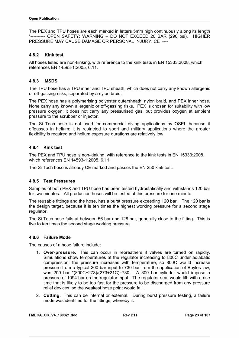
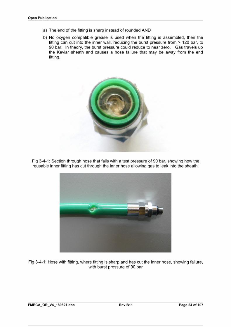
2. Cutting. This can be internal or external. During burst pressure testing, a failuremode was identified for the fittings, whereby if:
FMECA_OR_V4_180821.doc Rev B11 Page 23 of 107
Open Publication
a) The end of the fitting is sharp instead of rounded AND
b) No oxygen compatible grease is used when the fitting is assembled, then thefitting can cut into the inner wall, reducing the burst pressure from > 120 bar, to90 bar. In theory, the burst pressure could reduce to near zero. Gas travels upthe Kevlar sheath and causes a hose failure that may be away from the endfitting.
Fig 3-4-1: Section through hose that fails with a test pressure of 90 bar, showing how thereusable inner fitting has cut through the inner hose allowing gas to leak into the sheath.
Fig 3-4-1: Hose with fitting, where fitting is sharp and has cut the inner hose, showing failure,with burst pressure of 90 bar
FMECA_OR_V4_180821.doc Rev B11 Page 24 of 107
Open Publication
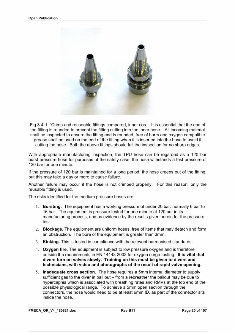
Fig 3-4-1: “Crimp and reuseable fittings compared, inner core. It is essential that the end ofthe fitting is rounded to prevent the fitting cutting into the inner hose. All incoming materialshall be inspected to ensure the fitting end is rounded, free of burrs and oxygen compatible
grease shall be used on the end of the fitting when it is inserted into the hose to avoid itcutting the hose. Both the above fittings should fail the inspection for no sharp edges.
With appropriate manufacturing inspection, the TPU hose can be regarded as a 120 barburst pressure hose for purposes of the safety case: the hose withstands a test pressure of120 bar for one minute.
If the pressure of 120 bar is maintained for a long period, the hose creeps out of the fitting,but this may take a day or more to cause failure.
Another failure may occur if the hose is not crimped properly. For this reason, only thereusable fitting is used.
The risks identified for the medium pressure hoses are:
1. Bursting. The equipment has a working pressure of under 20 bar: normally 6 bar to 16 bar. The equipment is pressure tested for one minute at 120 bar in its manufacturing process, and as evidence by the results given herein for the pressure test.
2. Blockage. The equipment are uniform hoses, free of items that may detach and forman obstruction. The bore of the equipment is greater than 3mm.
3. Kinking. This is tested in compliance with the relevant harmonised standards.
4. Oxygen fire. The equipment is subject to low pressure oxygen and is therefore outside the requirements in EN 14143:2003 for oxygen surge testing. It is vital that divers turn on valves slowly. Training on this must be given to divers and technicians, with video and photographs of the result of rapid valve opening.
5. Inadequate cross section. The hose requires a 5mm internal diameter to supply sufficient gas to the diver in bail out – from a rebreather the bailout may be due to hypercapnia which is associated with breathing rates and RMVs at the top end of the possible physiological range. To achieve a 5mm open section through the connectors, the hose would need to be at least 6mm ID, as part of the connector sits inside the hose.
FMECA_OR_V4_180821.doc Rev B11 Page 25 of 107
Open Publication
Toxicity. The equipment does not contain any substance known to have any significanttoxicity. A MSDS is provided with this Technical File for each material used in theequipment.
4.9 Breathing Hose Ports
4.9.1 Design Decision Review
The ports connect the breathing hoses to the mouthpiece, Counterlungs and scrubber.
There are three types of port in common use:
1. Screw connection ports. These carry risks of cross-threading, no matter how largethe thread is, the thread is invariably external on one part of the port with risk ofthread damage, the thread traps contaminants and there is no clear indication to theuser that the thread is properly engaged: the user stops turning the nut whenresistance is felt – this may be due to thread damage. There is considerableoperational experience of using screw connection ports, but the hazards associatedwith them are intrinsic to their design.
2. Bayonet type ports. These depend on the pins which can be damaged easily. Thebayonet generally has a sequence of actions, which can occur by accident: push,rotate, pull – the push and pull can be a byproduct of the difference in pressure insidethe loop and externally, during pre-dive checks. There is little operational experienceof using bayonet ports.
3. Press-Click Ports. These are the most widely used ports for Multi-role professionalrebreathers, exemplified by the Draeger P Port, by virtue of the large sales volumefrom Draeger Dolphin and Ray rebreathers, and the use of similar Press-Click portson rebreathers from other OEMs.
The design is a Press-Click type port developed after testing ports in common use, aHAZOP study, and then a development project to address all of the limitations identifiedduring either testing or from the HAZOP. The use of a Press-Click connector as the basisfor this development appears to be the optimal decision.
4.9.2 Risk Assessment
The risks presented by the Press-Click Ports in common use are:
1. The bore of the Draeger P Port is just 22mm – 24mm. This presents significant breathing resistance: it is more than that of an oro-nasal mask, and more than theflapper valves in common designs. The bore presents a risk of CO2 retention due to increased Work Of Breathing.This risk was addressed within the project by establishing a minimum bore of 36mm, giving a 10.17cm² gas cross section compared to 3.8cm² for the P Port. The reason for choosing 36mm is that the sum of all the port obstructions then becomes equal to the resistance of the flapper valve, after optimisation.
2. The Press-Click Ports that were examined were found to fall apart readily: pressing the plastic around the port on two opposite sides just behind the button was sufficient in most cases.This risk was overcome by increasing the thickness of the plastic and screwing the parts together from behind instead of relying on clip fit assembly.
3. The Press-Click Ports generally have a single O-ring, and as the ports act in series, it would mean that if any one O-ring failed, then the loop failed. This risk was addressed by designing in double O-rings. Both act in piston mode,
FMECA_OR_V4_180821.doc Rev B11 Page 26 of 107
Open Publication
as this is the most reliable form of moving O-ring seal in practice. The O-ring pressure was also increased such that if a ring is lost, there is less space for water to ingress through.
4. The Press-Click Ports that were tested did not mate securely: it was not clear if the ports were fully engaged or not.This risk was addressed by using a locking channel that is significantly deeper and wider than ports in common use, for a very positive "click".A further change was made to add a white line to the button(s) such that it is visible only when properly engaged. This gives clear visible feedback to the user that the port is engaged properly.
5. The ports in common use could be disconnected by pulling hard enough on the hose.This risk was addressed by increasing the depth of the wire retainer groove and increasing the diameter of the clip wire by 50% over that of ports in common use.
6. The P Ports in common use could be pulled through the counterlung if the counterlung material was under tension. This risk is considered under the counterlung assembly, but required specific design features to be incorporated into the port to enable a secure seal and to retain the port onto a lip on the counterlung.
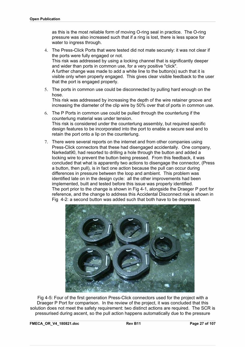
7. There were several reports on the internet and from other companies using Press-Click connectors that these had disengaged accidentally. One company, Narkedat90, had resorted to drilling a hole through the button and added a locking wire to prevent the button being pressed. From this feedback, it was concluded that what is apparently two actions to disengage the connector, (Pressa button, then pull), is in fact one action because the pull can occur during differences in pressure between the loop and ambient. This problem was identified late on in the design cycle: all the other improvements had been implemented, built and tested before this issue was properly identified.The port prior to the change is shown in Fig 4-1, alongside the Draeger P port for reference, and the change to address this Accidental Disconnect risk is shown in Fig 4-2: a second button was added such that both have to be depressed.
Fig 4-5: Four of the first generation Press-Click connectors used for the project with aDraeger P Port for comparison. In the review of the project, it was concluded that this
solution does not meet the safety requirement: two distinct actions are required. The SCR ispressurised during ascent, so the pull action happens automatically due to the pressure
FMECA_OR_V4_180821.doc Rev B11 Page 27 of 107
Open Publication
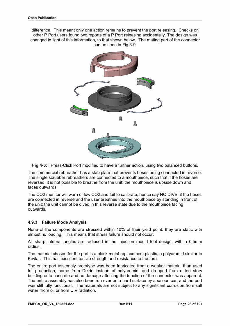
difference. This meant only one action remains to prevent the port releasing. Checks onother P Port users found two reports of a P Port releasing accidentally. The design was
changed in light of this information, to that shown below. The mating part of the connectorcan be seen in Fig 3-9.
Fig 4 - 6 : Press-Click Port modified to have a further action, using two balanced buttons.
The commercial rebreather has a stab plate that prevents hoses being connected in reverse.The single scrubber rebreathers are connected to a mouthpiece, such that if the hoses are reversed, it is not possible to breathe from the unit: the mouthpiece is upside down and faces outwards.
The CO2 monitor will warn of low CO2 and fail to calibrate, hence say NO DIVE, if the hosesare connected in reverse and the user breathes into the mouthpiece by standing in front of the unit: the unit cannot be dived in this reverse state due to the mouthpiece facing outwards.
4.9.3 Failure Mode Analysis
None of the components are stressed within 10% of their yield point: they are static withalmost no loading. This means that stress failure should not occur.
All sharp internal angles are radiused in the injection mould tool design, with a 0.5mmradius.
The material chosen for the port is a black metal replacement plastic, a polyaramid similar toKevlar. This has excellent tensile strength and resistance to fracture.
The entire port assembly prototype was been fabricated from a weaker material than usedfor production, name from Delrin instead of polyaramid, and dropped from a ten storybuilding onto concrete and no damage affecting the function of the connector was apparent.The entire assembly has also been run over on a hard surface by a saloon car, and the portwas still fully functional. The materials are not subject to any significant corrosion from saltwater, from oil or from U.V radiation.
FMECA_OR_V4_180821.doc Rev B11 Page 28 of 107
Open Publication
Errors in assembly or from wear are apparent to the user in that the white line on the buttonsis not visible when engaged: this is a fail safe failure. The button may also stick if grit orcontaminants invade its sliding surfaces: this results in the white line not being visible whenengaged, which is a fail safe failure.
The O-rings require preventative maintenance in the form of cleaning if contaminated withgrit or oil, and annual replacement. The O-ring material is EPDM which has excellent U.V.resistance and good resistance to ozone which occurs in a welding environment, unlikeViton or butyl. EPDM has good dynamic wear properties.
EPDM is a synthetic plastic and does not carry the allergenic risks of latex based rubbers.
There are no plausible failure modes identified, that do not result in the port failing positive ornegative pressure tests or a cursory visible inspection by the user.
The plastics manufacture has confirmed the plastic granules contain no plasticizer. Toxicchemicals include formaldehyde are generated when the plastic is burnt, but this requirestemperatures of over 200C.
4.10 Water Dumps
4.10.1 Design Decision Review
The water dumps have been the subject of considerable ergonomic testing, to find the besttype and location.
Automatic water dumps were found both by formal modelling and in manned trials, to beunusable because the pressure differential needed to actuate them fights the pressuredifferential to trigger the Over Pressure Valve.
Manual dumps were concluded, located at the bottom of each of the counterlungs. Thewater dump is a 30mm diameter and requires between 1kg and 1.5kg to actuate it, so it willnot trigger automatically.
An extended review of the water dumps considered whether these should be single ordouble valve design. With a single dump, pulling the dump opens the breathing loop. With adouble valve, water ingress to the loop is prevented by use of a second flapper valve, butthen in the event the water dump is pulled, the diver would suffer water ingress wheninverted – the period of time between the dump being pulled or entrapped and the loss ofgas would then make the cause of the water ingress to become unrelated for the diver,making its rectification much less likely.
The design used on all O.R. rebreather models uses a twin valve, combining a pull-dumpand a one-way valve to prevent water ingress.
The pull dump has a different knob than that for BCDs that can be distinguished by feel,even though thick gloves.
The pull dump has a tube over the pull cord to prevent the pull cord entangling with cylindervalves.
4.10.2 Risk Assessment
The manual dump could be pulled accidentally, resulting in a complete loss of the breathingloop.
The manual dump cord could fail.
The manual dump could pull away from the counterlung. This is mitigated, or eliminated, bythe use of an injection moulded port reinforcing ring that is welded to the counterlung.
FMECA_OR_V4_180821.doc Rev B11 Page 29 of 107
Open Publication
4.10.3 Failure Mode Analysis
The failure modes of the water dump are:
Stuck open. The two Training Managers, Paul Haynes and Gregg Stanton, indicatedthat a double valve dump was strongly preferred, and that the isolation of the causalevent and the manifestation of the failure should the dump be pulled, is less of anissue than water ingress to the loop. All water dump valves are double valves.
Stuck shut. This can be caused by breakage of the pull cord, or the pull cord comingaway from the pull toggle. The hazard is mitigated by their protected location, andthe use of two water dumps, only one of which need operate.
Slow leak. This is a subset of stuck open. The valve seat on all BCD dump valvesthat were tested carry a risk of not seating correctly because the spring places anuneven force on the valve stopper. A total redesign and retooling of the valve wascarried out to move the stopped as a piston so it is unable to move sideways. Thischange involved total retooling of 7 parts: it was carried out as the improved design issafer.
Entanglement. This is mitigated by their protected location and the choice of pulldumps that are of a low snag design: a pear shape instead of a ring or hoop. Afurther mitigation made in May 2010 onwards was the use of a rigid tube over the pullcord to prevent it entangling in cylinder valves, subsequently changed to shorted thecord such that there is no free cord that may tangle.
The version of the water dump that is installed in all counterlungs has an umbrella valve(one-way valve) fitted to prevent water ingress.
Test diver reported in May 2010 that in a pre-dive check a slow leak was seen from a waterdump, due to the cord entangling. Like any other fault that is reported, this was treated inaccordance with Deep Life’s QP-20 functional safety processes: an entry was made on tothe Mantis tracking system, it was reviewed and a mitigation was found by fitting a Bowdencable: this involves placing a semi-rigid small bore pneumatic tube to cover the pull dumpcord. This was reviewed, and changed to shorten the cord such that there is no spare cord:the pull-stop is held against the case.
One customer reported that it is possible for the stopped to partially seal: this is a knownfailure mode of all BCD dump valves. The fault rectifies itself if the valve is pulled again andreleased. Twelve different types of BCD dump was tested and all could exhibit the fault.However, in the review process it was concluded that a better design was feasible, using acaptive piston to prevent sideways movement. This eliminates this fault mode. Such adesign was then carried out and tooled. Images of the result are shown below: original andimproved.
FMECA_OR_V4_180821.doc Rev B11 Page 30 of 107
Open Publication
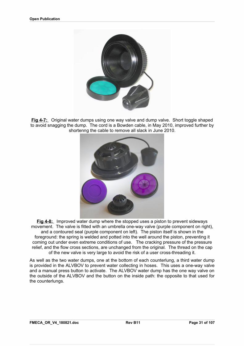
Fig 4 - 7 : Original water dumps using one way valve and dump valve. Short toggle shapedto avoid snagging the dump. The cord is a Bowden cable, in May 2010, improved further by
shortenng the cable to remove all slack in June 2010.
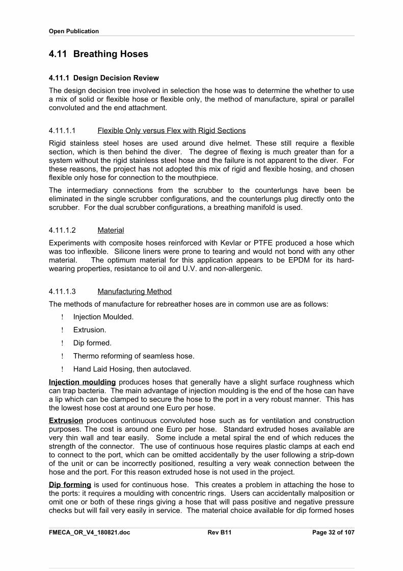
Fig 4 - 8 : Improved water dump where the stopped uses a piston to prevent sidewaysmovement. The valve is fitted with an umbrella one-way valve (purple component on right),
and a contoured seal (purple component on left). The piston itself is shown in theforeground: the spring is welded and potted into the well around the piston, preventing it
coming out under even extreme conditions of use. The cracking pressure of the pressurerelief, and the flow cross sections, are unchanged from the original. The thread on the cap
of the new valve is very large to avoid the risk of a user cross-threading it.
As well as the two water dumps, one at the bottom of each counterlung, a third water dumpis provided in the ALVBOV to prevent water collecting in hoses. This uses a one-way valveand a manual press button to activate. The ALVBOV water dump has the one way valve onthe outside of the ALVBOV and the button on the inside path: the opposite to that used forthe counterlungs.
FMECA_OR_V4_180821.doc Rev B11 Page 31 of 107
Open Publication
4.11 Breathing Hoses
4.11.1 Design Decision Review
The design decision tree involved in selection the hose was to determine the whether to usea mix of solid or flexible hose or flexible only, the method of manufacture, spiral or parallelconvoluted and the end attachment.
4.11.1.1 Flexib l e Only versus Flex with Rigid Sections
Rigid stainless steel hoses are used around dive helmet. These still require a flexiblesection, which is then behind the diver. The degree of flexing is much greater than for asystem without the rigid stainless steel hose and the failure is not apparent to the diver. Forthese reasons, the project has not adopted this mix of rigid and flexible hosing, and chosenflexible only hose for connection to the mouthpiece.
The intermediary connections from the scrubber to the counterlungs have been beeliminated in the single scrubber configurations, and the counterlungs plug directly onto thescrubber. For the dual scrubber configurations, a breathing manifold is used.
4.11.1.2 Material
Experiments with composite hoses reinforced with Kevlar or PTFE produced a hose whichwas too inflexible. Silicone liners were prone to tearing and would not bond with any othermaterial. The optimum material for this application appears to be EPDM for its hard-wearing properties, resistance to oil and U.V. and non-allergenic.
4.11.1.3 Manufacturing Method
The methods of manufacture for rebreather hoses are in common use are as follows:
Injection Moulded.
Extrusion.
Dip formed.
Thermo reforming of seamless hose.
Hand Laid Hosing, then autoclaved.
Injection moulding produces hoses that generally have a slight surface roughness whichcan trap bacteria. The main advantage of injection moulding is the end of the hose can havea lip which can be clamped to secure the hose to the port in a very robust manner. This hasthe lowest hose cost at around one Euro per hose.
Extrusion produces continuous convoluted hose such as for ventilation and constructionpurposes. The cost is around one Euro per hose. Standard extruded hoses available arevery thin wall and tear easily. Some include a metal spiral the end of which reduces thestrength of the connector. The use of continuous hose requires plastic clamps at each endto connect to the port, which can be omitted accidentally by the user following a strip-downof the unit or can be incorrectly positioned, resulting a very weak connection between thehose and the port. For this reason extruded hose is not used in the project.
Dip forming is used for continuous hose. This creates a problem in attaching the hose tothe ports: it requires a moulding with concentric rings. Users can accidentally malposition oromit one or both of these rings giving a hose that will pass positive and negative pressurechecks but will fail very easily in service. The material choice available for dip formed hoses
FMECA_OR_V4_180821.doc Rev B11 Page 32 of 107
Open Publication
is also limited: generally butyl rubbers are used or PU. The cost of dip formed hoses isaround four times that of injection moulded hoses.
Thermo-reforming produces hoses with a smooth cuff and either parallel or spiralconvolutions. The strength of the hose is less than that for injection moulding: samplesfailed in pull tests with around 50kg load. The failure is a complete breakage of the hosebecause there is a small cut in the hose on each convolution where the tool has grabbed thehose during manufacture. When a stress crack extends from the outer surface to the inner,it travels almost immediately around the circumference of the hose. Special attention toensure that these cuts are minimised needs to be given. Other than this, the raw material inthermo-reformed hoses is very smooth and uniform. The hoses can stretch 400%: twice thatof hoses manufactured using other processes. The hose cost is three times that of injectionmoulded hoses.
Hand laid hosing produces hoses around a mandrel. The layer process is of a concern, asit can trap gas even after autoclaving which could expand during decompression in asaturation diving environment. The process appears to be a low volume alternative to amoulded hose, with the benefit that stress cracks are unlikely to penetrate from layer tolayer. The cost of these hoses is typically 30 times higher than that for injection mouldedhose.
4.11.1.4 Overall Assessment
Thermo-reformed EPDM hoses have been selected for the project, but this may becomeinjection moulded later using a very smooth mould core. The design uses a spiralconvolution to enable water to drain easily from the hose.
The hoses have a strong protective cover to prevent accidental damage manufactured from1000 Cordura, or from oil and cut resistant two ply commercial dry suit material dependingon the application. The cover is closed with Velcro.
4.11.2 Compliance
EN14143:2003 Section 5.8.8 Breathing hoseThe breathing hose shall be flexible and non-kinking.
The meaning of “non-kinking” in the standard is understood to be when the hose is bent 180 degrees, it does not flatten and close off the gas passage completely or near completely. The DL hoses do not kink. However, during negative pressure tests it is highly desirable thatthe hose can be deformed into an axial kink and retain that position subject to negative pres-sure being maintained: the hose does this, and releases the kink automatically when negat-ive pressure is removed.
To check this understanding, hoses from other units carrying a CE marking were checked TPF
1FPT.
The Buddy Inspiration hose was tested with a 180 degree bend, and the hose kinked, redu-cing the bore to near zero. The Draeger Dolphin hose reduced in bore by 90% but did not kink – however the hazard of such hose that is nearly closed is the same as for a kink.
1
TP
�PT Neither the Draeger Dolphin nor the Buddy Inspiration are certified to EN14143, but use a
historic PPE Directive compliance based on specifications each company has written in house todescribe its own product. However, as both claim to meet the PPE Directive, then these shall beused as reference points.FMECA_OR_V4_180821.doc Rev B11 Page 33 of 107
Open Publication
The DL hose did not kink and the bore did not reduce to less than 35mm in diameter: it was the only safe hose of the three hose types tested.
EN14143:2003 Section 5.8.8 Breathing hoseThe breathing hose shall permit free head movement and shall not restrict or close off the gas supply under chin or arm pressure during practical performance tests. Testing shall be done in accordance with 6.15.
Three hose samples were used and all pass this test.
The DL hoses are much shorter than hoses on other rebreathers, with provision to adjust theeffective length.
EN14143:2003 Section 5.8.8 Breathing hoseThe hose shall not collapse and the elongation shall be at least 10 % and not greater than 30 %. Testing shall be done in accordance with 6.8.5.
EN14143:2003 Section 6.8.5 Flexibility of breathing hoses
Suspend the breathing hose assembly for testing elongation. Measure the hose length (without couplings).Afterwards apply a force of 10 N to the hose assembly for a period of 5 min and measure and record thelength of the hose. Calculate the elongation (%).
The DL hoses meet the requirement that the hose does not collapse.
It is not clear why there is a limit of 30% on elongation: in fact it creates a safety hazardbecause much longer hose lengths are required to allow sufficient head movement than arerequired in an optimal design, and a non-kinking hose requires much more than a 30%stretch otherwise it will block off the gas pass (for example, the Draeger Dolphin hoseblocked 90% of the flow diameter in the kink test). The standard relates to over the headtype hose designs and has been unduly influenced by these.
The optimum hose design stretches 400% on a 25kg load, without permanent deformation,and this allows the length of the hose to be reduced by a factor of 3.8 compared to a hosethat only stretches by 30%, considerably reducing the area exposed to puncture and alsoreducing the weight of the unit (reduced dead gas space).
Several contemporary hoses from other CE marked rebreathers were tested to see howother companies comply with this strange requirement. The results using the 10N (1kg) loadhere were:
Hose manufacturer Material /Construction
Hose bore
OD/ID (mm)
Free hoselength
(mm)
Hose lengthunder 10 N
(mm)
Elongation
(%)
DL Large Bore EPDMThermoformedfor application
54/36 150 400 260
DL Small Bore EPDM
Thermoformedfor application
48/31 150 400 260
Draeger LAR5 EPDMInjection
moulded forapplication
45/30 400 560 40
Draeger
Dolphin
EPDMInjection
moulded for
47/34 500 580 16
FMECA_OR_V4_180821.doc Rev B11 Page 34 of 107
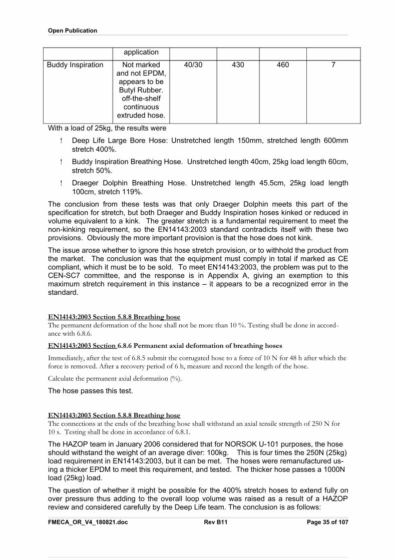
Open Publication
application
Buddy Inspiration Not markedand not EPDM,appears to beButyl Rubber.off-the-shelfcontinuous
extruded hose.
40/30 430 460 7
With a load of 25kg, the results were
Deep Life Large Bore Hose: Unstretched length 150mm, stretched length 600mmstretch 400%.
Buddy Inspiration Breathing Hose. Unstretched length 40cm, 25kg load length 60cm,stretch 50%.
Draeger Dolphin Breathing Hose. Unstretched length 45.5cm, 25kg load length100cm, stretch 119%.
The conclusion from these tests was that only Draeger Dolphin meets this part of thespecification for stretch, but both Draeger and Buddy Inspiration hoses kinked or reduced involume equivalent to a kink. The greater stretch is a fundamental requirement to meet thenon-kinking requirement, so the EN14143:2003 standard contradicts itself with these twoprovisions. Obviously the more important provision is that the hose does not kink.
The issue arose whether to ignore this hose stretch provision, or to withhold the product fromthe market. The conclusion was that the equipment must comply in total if marked as CEcompliant, which it must be to be sold. To meet EN14143:2003, the problem was put to theCEN-SC7 committee, and the response is in Appendix A, giving an exemption to thismaximum stretch requirement in this instance – it appears to be a recognized error in thestandard.
EN14143:2003 Section 5.8.8 Breathing hoseThe permanent deformation of the hose shall not be more than 10 %. Testing shall be done in accord-ance with 6.8.6.
EN14143:2003 Section 6.8.6 Permanent axial deformation of breathing hoses
Immediately, after the test of 6.8.5 submit the corrugated hose to a force of 10 N for 48 h after which theforce is removed. After a recovery period of 6 h, measure and record the length of the hose.
Calculate the permanent axial deformation (%).
The hose passes this test.
EN14143:2003 Section 5.8.8 Breathing hoseThe connections at the ends of the breathing hose shall withstand an axial tensile strength of 250 N for 10 s. Testing shall be done in accordance of 6.8.1.
The HAZOP team in January 2006 considered that for NORSOK U-101 purposes, the hose should withstand the weight of an average diver: 100kg. This is four times the 250N (25kg)load requirement in EN14143:2003, but it can be met. The hoses were remanufactured us-ing a thicker EPDM to meet this requirement, and tested. The thicker hose passes a 1000N load (25kg) load.
The question of whether it might be possible for the 400% stretch hoses to extend fully onover pressure thus adding to the overall loop volume was raised as a result of a HAZOPreview and considered carefully by the Deep Life team. The conclusion is as follows:
FMECA_OR_V4_180821.doc Rev B11 Page 35 of 107
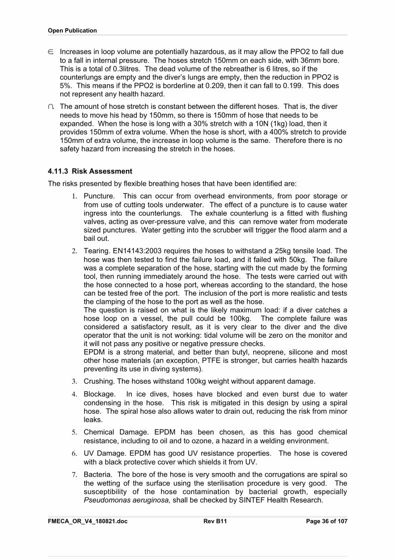
Open Publication
a. Increases in loop volume are potentially hazardous, as it may allow the PPO2 to fall due to a fall in internal pressure. The hoses stretch 150mm on each side, with 36mm bore. This is a total of 0.3litres. The dead volume of the rebreather is 6 litres, so if the counterlungs are empty and the diver’s lungs are empty, then the reduction in PPO2 is 5%. This means if the PPO2 is borderline at 0.209, then it can fall to 0.199. This does not represent any health hazard.
b. The amount of hose stretch is constant between the different hoses. That is, the diver needs to move his head by 150mm, so there is 150mm of hose that needs to be expanded. When the hose is long with a 30% stretch with a 10N (1kg) load, then it provides 150mm of extra volume. When the hose is short, with a 400% stretch to provide150mm of extra volume, the increase in loop volume is the same. Therefore there is no safety hazard from increasing the stretch in the hoses.
4.11.3 Risk Assessment
The risks presented by flexible breathing hoses that have been identified are:
1. Puncture. This can occur from overhead environments, from poor storage orfrom use of cutting tools underwater. The effect of a puncture is to cause wateringress into the counterlungs. The exhale counterlung is a fitted with flushingvalves, acting as over-pressure valve, and this can remove water from moderatesized punctures. Water getting into the scrubber will trigger the flood alarm and abail out.
2. Tearing. EN14143:2003 requires the hoses to withstand a 25kg tensile load. Thehose was then tested to find the failure load, and it failed with 50kg. The failurewas a complete separation of the hose, starting with the cut made by the formingtool, then running immediately around the hose. The tests were carried out withthe hose connected to a hose port, whereas according to the standard, the hosecan be tested free of the port. The inclusion of the port is more realistic and teststhe clamping of the hose to the port as well as the hose.The question is raised on what is the likely maximum load: if a diver catches ahose loop on a vessel, the pull could be 100kg. The complete failure wasconsidered a satisfactory result, as it is very clear to the diver and the diveoperator that the unit is not working: tidal volume will be zero on the monitor andit will not pass any positive or negative pressure checks.EPDM is a strong material, and better than butyl, neoprene, silicone and mostother hose materials (an exception, PTFE is stronger, but carries health hazardspreventing its use in diving systems).
3. Crushing. The hoses withstand 100kg weight without apparent damage.
4. Blockage. In ice dives, hoses have blocked and even burst due to watercondensing in the hose. This risk is mitigated in this design by using a spiralhose. The spiral hose also allows water to drain out, reducing the risk from minorleaks.
5. Chemical Damage. EPDM has been chosen, as this has good chemicalresistance, including to oil and to ozone, a hazard in a welding environment.
6. UV Damage. EPDM has good UV resistance properties. The hose is coveredwith a black protective cover which shields it from UV.
7. Bacteria. The bore of the hose is very smooth and the corrugations are spiral sothe wetting of the surface using the sterilisation procedure is very good. Thesusceptibility of the hose contamination by bacterial growth, especiallyPseudomonas aeruginosa, shall be checked by SINTEF Health Research.
FMECA_OR_V4_180821.doc Rev B11 Page 36 of 107
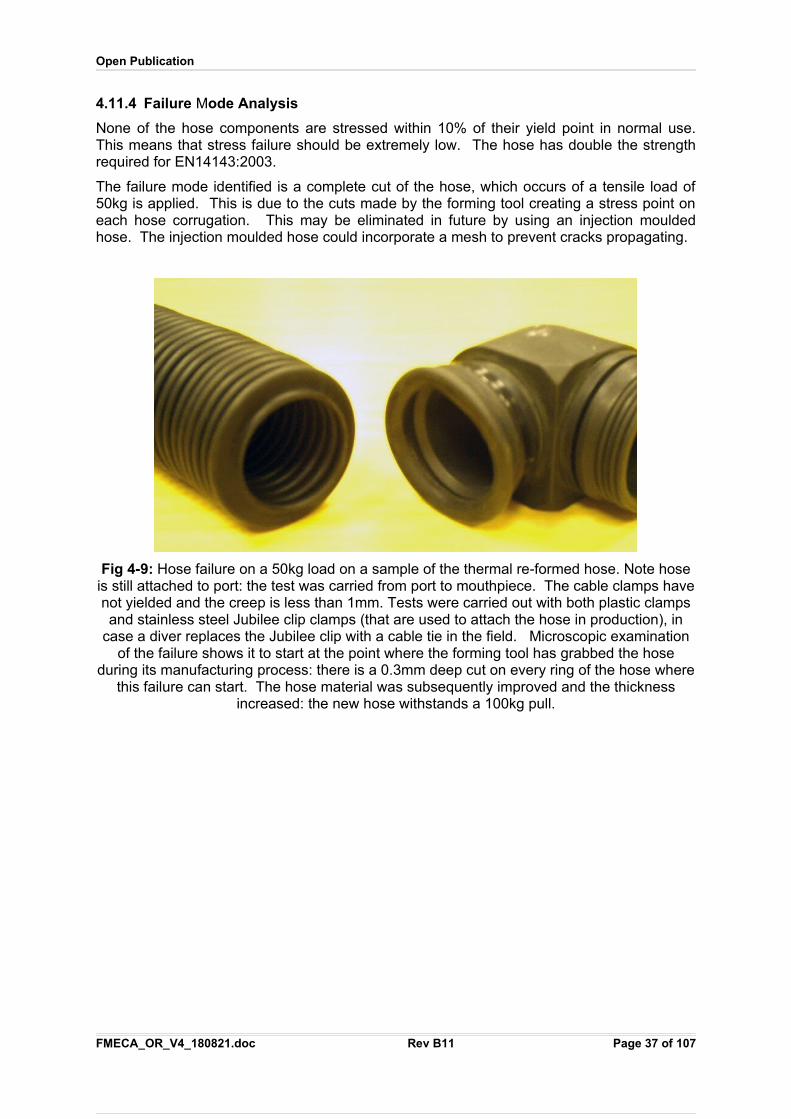
Open Publication
4.11.4 Failure Mode Analysis
None of the hose components are stressed within 10% of their yield point in normal use.This means that stress failure should be extremely low. The hose has double the strengthrequired for EN14143:2003.
The failure mode identified is a complete cut of the hose, which occurs of a tensile load of50kg is applied. This is due to the cuts made by the forming tool creating a stress point oneach hose corrugation. This may be eliminated in future by using an injection mouldedhose. The injection moulded hose could incorporate a mesh to prevent cracks propagating.
Fig 4-9: Hose failure on a 50kg load on a sample of the thermal re-formed hose. Note hoseis still attached to port: the test was carried from port to mouthpiece. The cable clamps havenot yielded and the creep is less than 1mm. Tests were carried out with both plastic clampsand stainless steel Jubilee clip clamps (that are used to attach the hose in production), in
case a diver replaces the Jubilee clip with a cable tie in the field. Microscopic examinationof the failure shows it to start at the point where the forming tool has grabbed the hose
during its manufacturing process: there is a 0.3mm deep cut on every ring of the hose wherethis failure can start. The hose material was subsequently improved and the thickness
increased: the new hose withstands a 100kg pull.
FMECA_OR_V4_180821.doc Rev B11 Page 37 of 107
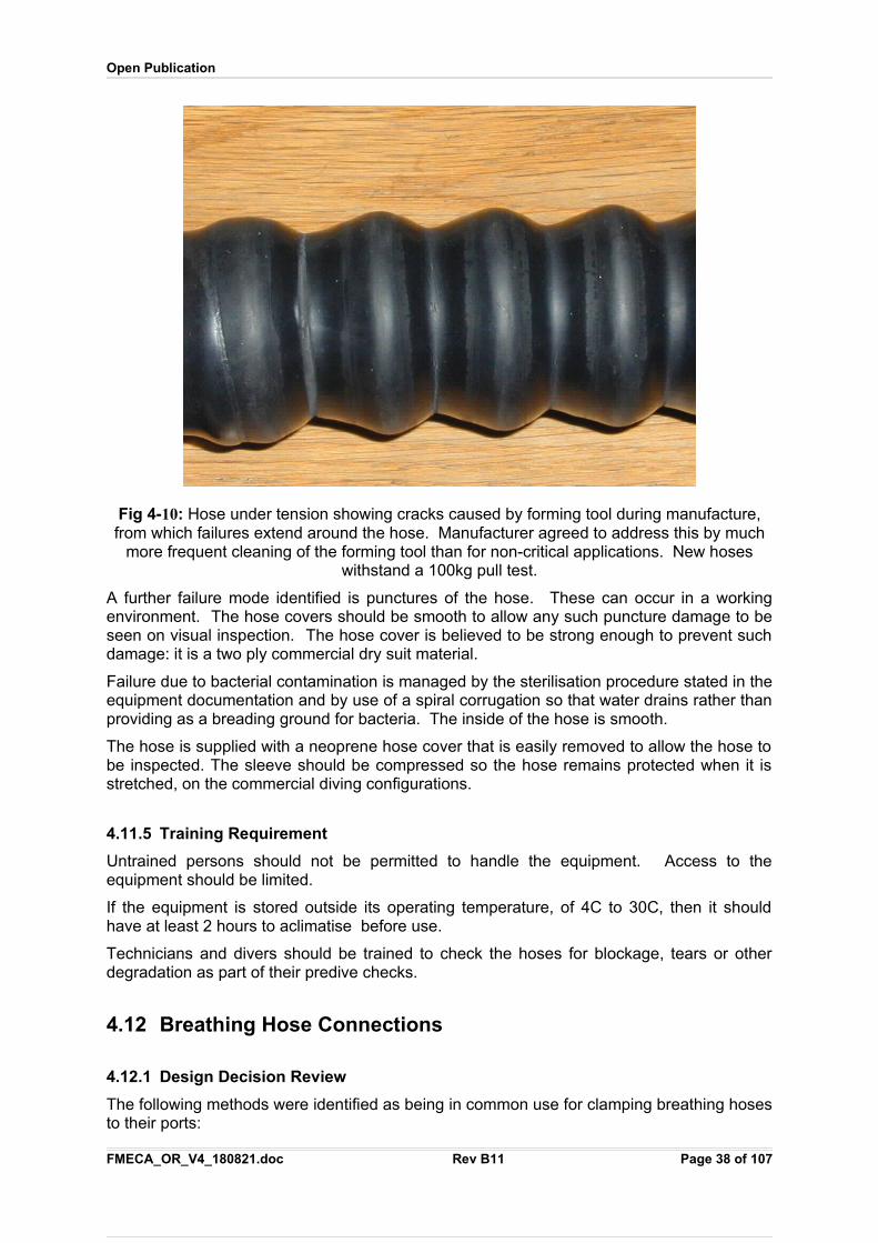
Open Publication
Fig 4-10: Hose under tension showing cracks caused by forming tool during manufacture,from which failures extend around the hose. Manufacturer agreed to address this by much
more frequent cleaning of the forming tool than for non-critical applications. New hoseswithstand a 100kg pull test.
A further failure mode identified is punctures of the hose. These can occur in a workingenvironment. The hose covers should be smooth to allow any such puncture damage to beseen on visual inspection. The hose cover is believed to be strong enough to prevent suchdamage: it is a two ply commercial dry suit material.
Failure due to bacterial contamination is managed by the sterilisation procedure stated in theequipment documentation and by use of a spiral corrugation so that water drains rather thanproviding as a breading ground for bacteria. The inside of the hose is smooth.
The hose is supplied with a neoprene hose cover that is easily removed to allow the hose tobe inspected. The sleeve should be compressed so the hose remains protected when it isstretched, on the commercial diving configurations.
4.11.5 Training Requirement
Untrained persons should not be permitted to handle the equipment. Access to theequipment should be limited.
If the equipment is stored outside its operating temperature, of 4C to 30C, then it shouldhave at least 2 hours to aclimatise before use.
Technicians and divers should be trained to check the hoses for blockage, tears or otherdegradation as part of their predive checks.
4.12 Breathing Hose Connections
4.12.1 Design Decision Review
The following methods were identified as being in common use for clamping breathing hosesto their ports:
FMECA_OR_V4_180821.doc Rev B11 Page 38 of 107
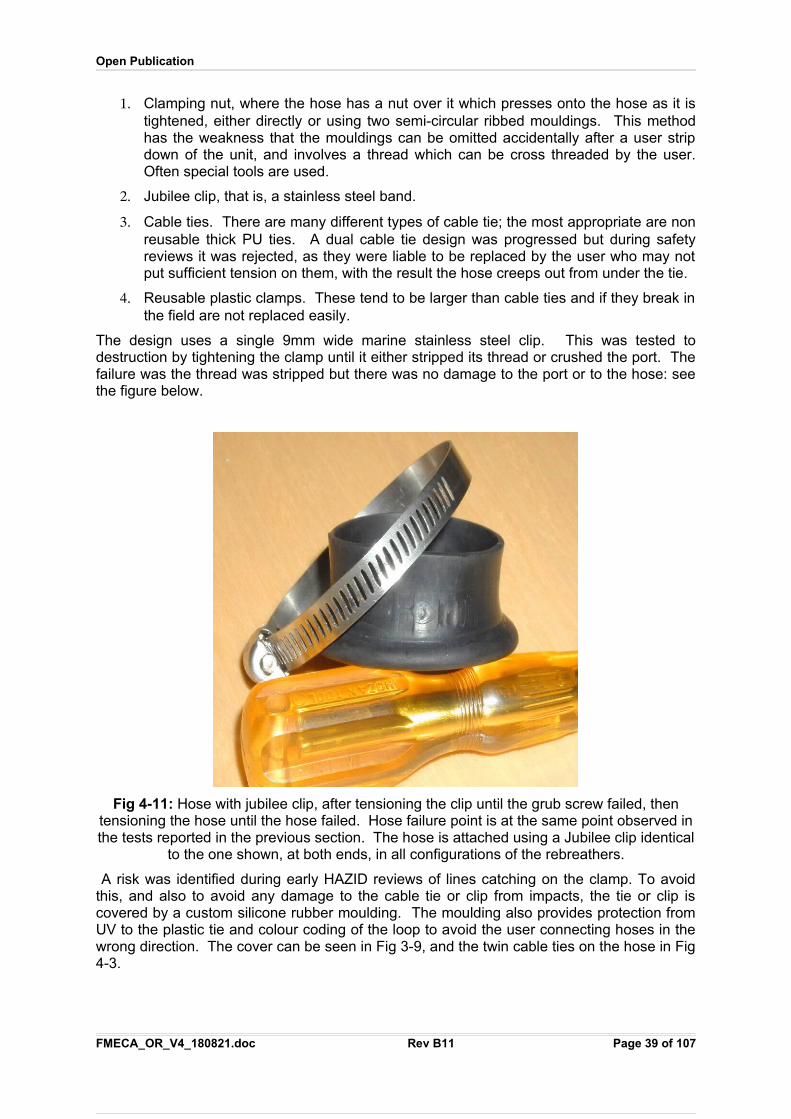
Open Publication
1. Clamping nut, where the hose has a nut over it which presses onto the hose as it istightened, either directly or using two semi-circular ribbed mouldings. This methodhas the weakness that the mouldings can be omitted accidentally after a user stripdown of the unit, and involves a thread which can be cross threaded by the user.Often special tools are used.
2. Jubilee clip, that is, a stainless steel band.
3. Cable ties. There are many different types of cable tie; the most appropriate are nonreusable thick PU ties. A dual cable tie design was progressed but during safetyreviews it was rejected, as they were liable to be replaced by the user who may notput sufficient tension on them, with the result the hose creeps out from under the tie.
4. Reusable plastic clamps. These tend to be larger than cable ties and if they break inthe field are not replaced easily.
The design uses a single 9mm wide marine stainless steel clip. This was tested todestruction by tightening the clamp until it either stripped its thread or crushed the port. Thefailure was the thread was stripped but there was no damage to the port or to the hose: seethe figure below.
Fig 4-11: Hose with jubilee clip, after tensioning the clip until the grub screw failed, thentensioning the hose until the hose failed. Hose failure point is at the same point observed inthe tests reported in the previous section. The hose is attached using a Jubilee clip identical
to the one shown, at both ends, in all configurations of the rebreathers.
A risk was identified during early HAZID reviews of lines catching on the clamp. To avoidthis, and also to avoid any damage to the cable tie or clip from impacts, the tie or clip iscovered by a custom silicone rubber moulding. The moulding also provides protection fromUV to the plastic tie and colour coding of the loop to avoid the user connecting hoses in thewrong direction. The cover can be seen in Fig 3-9, and the twin cable ties on the hose in Fig4-3.
FMECA_OR_V4_180821.doc Rev B11 Page 39 of 107
Open Publication
The clip cover is made from silicone, not EPDM: a batch of EPDM samples in 60 and 70durometer material was fabricated but found to yield immediately, then stretch. This meantthe cover would sit loosely on the clip rather than grip it tightly.
There is no lip on the end of the hose: this is considered desirable, but the manufacturercould not achieve this using the thermal reforming method used for the hose.
4.12.2 Risk Assessment
The risks presented by the hoses terminations that have been identified are:
1. UV damage to the cable tie. This is avoided by a silicone cover.
2. Mechanical damage to the cable tie. This is avoided by a silicone cover.
3. Chemical damage to the cable tie. The ties are compatible with the environment andresist chemicals that may occur in that environment, including oil and ozone.
4. Aging of the cable tie material. This is avoided by using a marine grade stainlesssteel. For the Multi-role professional unit the cable ties are a moulding that isrequired to be checked on annual service.
5. Incorrect assembly. All extraneous parts are eliminated from the design: thetermination comprises just the port, the hose, the two cable ties or Jubilee clip andthe clip cover. The cable ties should be replaced on annual servicing. There are noscrew threads to damage or trap contamination.
6. Off-gassing. The cable ties are replaced by stainless steel strapping on thecommercial unit where off-gassing into a saturation dive habitat would pose a risk tohealth.
7. Loose connection. If the connection is not sufficiently tight, the hose will creep outfrom under the ties or clip. The hose should be inspected by applying 25kg of tensileforce whenever the cable ties or clip is replaced or adjusted: creep should be muchless than 0.5mm.
4.12.3 Failure Mode Analysis
The failure mode for the hose connection is the hose comes off the connector. This is agross failure and would be detected during pre-dive checks: the unit will not pass positive ornegative pressure checks in this state.
In tests of the weakest form of the clamp, that of cable ties, creep of less than 1mm wasseen with the cable tie tightened as far as possible, and in the failure test of the hose, thehose failed before the cable tie showed any significant creepage.
Failures from UV, chemical and mechanical hazards are managed in the design by using atie cover.
Failure from the user misassembling the connection is avoided by using a very simple formof connection with minimal parts other than the tie cover.
4.13 O-rings and X-ringsO-rings are used in most subassemblies in the design. This analysis covers all places in thedesign where O-rings are used.
FMECA_OR_V4_180821.doc Rev B11 Page 40 of 107
Open Publication
4.13.1 Design Decision Review
There are several materials in common use for oxygen compatible O-rings. The onlymaterials without known health issues, that are not liable to failure in either UV or ozone, areEPDM and heavily carbon loaded silicone. EPDM has better dynamic wear properties, so isused for all O-rings. The EPDM O-ring is not readily available in any other colour exceptblack, so all O-rings in the unit are black.
A HAZOP on the O-rings was carried out: “HAZOP report O rings 070216.pdf”.
During the HAZOP each of the following O-ring positions was reviewed:
1. Hoses, Breathing. Dual O Rings, Ambient to Surface to Ambient pressure
2. Hoses, Electrical, Dual O Rings, Ambient to Surface pressure
3. Hoses, Gas Intermediate Pressure, Dual, Ambient to Surface to Ambient + 10 bar
4. Scrubber canister seal, Single thick, Ambient to Ambient
5. Scrubber cartridge seal, Dual, sleeve type seal, Ambient to Ambient
6. Pressure sensors (Gas contents), single, Ambient to High Pressure
7. Thermal expansion oil piston seals, single, Ambient to Ambient
8. Gas injector, dual, Ambient to Surface pressure
9. Counter Lung retaining ring, single + seal rings, Ambient to Ambient.
10. Mouthpiece X-rings, Ambient to Ambient.
The reliability of O-rings was reviewed, with comparison to hydraulic pistons such as onexcavators. Excavator hydraulic ram seals provides years of life in very poor conditions.The shape of these is designed for high pressure to ambient only. The wear of round sealsin the rebreather should be minimal under all plausible operating conditions.
It was noted that the dual Ambient to Ambient seals provide Ambient to Surface and Surfaceto Ambient, so the sealing pressure is high as well as reliable.
The HAZOP discussion on the scrubber canister seal concurred with the design decisionthat one thick O-ring was safer than two thin O Rings in this application.
The O-Rings are all black EPDM, which has good chemical resistance, good UV and ozoneresistance, and is strong mechanically with good wear properties, other than the cartridgeseal which is red and the scrubber seal which is orange, for ease of user inspection.
During the HAZOP on the O-rings, a detailed MSDS for Black EPDM was considered, andon further enquiry, was found to contain Thiram as a softener, a toxic substance. A speciallyformulated EPDM was procured to eliminate Thiram and all other softeners or plasticizers.
4.13.2 Risk Analysis
The risks presented by the O-rings that have been identified are:
1. UV damage. There is risk of UV damage if a hose is left on deck disconnected froma port, or disconnected in an environment where arc welding is being carried out.The material chosen for all the O-rings is EPDM or silicone, both of which have goodresistance to UV.
2. Chemical damage. Silicone and EPDM is compatible with the environment and resistchemicals that may occur in that environment, including oil and ozone. Silicone O-rings swell in the presence of silicone oil: this is considered separately.
FMECA_OR_V4_180821.doc Rev B11 Page 41 of 107
Open Publication
3. Contamination. If non O2 compatible grease is used, toxic VOCs are likely to beintroduced into the breathing loop. It is important that only approved O2 compatiblegrease is used anywhere in the rebreather.
4. Mechanical damage. This is most likely to occur from sand or grit on the matingsurface, or damage to the mating surface. All O-rings are piston type, that is slideinto a cylinder except for:
The half mask mouthpiece where a sliding O-ring is used around the mouthpieceopening and introducing a second seal would create too much friction,
Some penetrators where there is insufficient space and the O ring is entirelystatic,
The single O-ring fitted to the high pressure sensing port of the first stageregulators: this is an industry standard design of port that the present design hasno influence over.
5. The risk from O-ring failure is mitigated by using two O-rings in series in all locationswhere O-rings occur in which leakage would cause a significant detriment to healthor safety, such as isolation of the breathing loop from the surrounding sea water.
6. Mechanical damage to the mating face. The use of twin piston type O-rings mitigatesthis risk. The O-rings are set as deep into the mating parts as practicable to reducethe probability of both failing simultaneously. The tolerance around O-rings has beenreduced to reduce the effect of any O-ring failure to a non-critical event. A risk was identified during HAZOP reviews where if the scrubber canister end isdamaged, it can act as a cutting tool on the canister O-ring. This hazard should bemitigated by inspection procedures and training.
7. Cutting the O-ring on the edge of the mating barrel: this is avoided by use of a 15degree lead in on all surfaces with plain O-rings, and use of a rolled edge where anX-ring is used.
8. Omission of an O-ring. If both O-rings are omitted, the rebreather will still operate,other than the scrubber canister O-ring, but will leak slowly. The unit will not passeither positive or negative pressure tests in this state, which are enforced by thesystem when it is powered up and not in the water.
9. Replacement with unsuitable material. This has a similar failure mode as theomission of O-rings.
10. Replacement with the wrong size. In most cases, the part will not mate if the O-ring isthe wrong size. If a thinner O-ring is fitted, the failure is similar to that of omission ofan O-ring.
11. Wear. The O-rings should all be replaced on annual service. The O-rings cansupport considerable wear: ports have been tested dry, free of oxygen compatiblegrease, with many more matings than is likely to occur in a lifetime of service, withoutfailure. In the worst case, the failure is similar to that of omission of an O-ring.
4.13.3 Failure Mode Analysis
The failure mode for O-rings is that gas blows past the ring.
The tolerance around O-rings has been set such that this is not a catastrophic failure, otherthan for the scrubber canister. The scrubber canister is subject to special considerationlater.
Scrubber O-Rings: A test was performed on the effect of omission of the scrubber O-ring and determine the survivability of such a complete ring failure. The onus was to either prove
FMECA_OR_V4_180821.doc Rev B11 Page 42 of 107
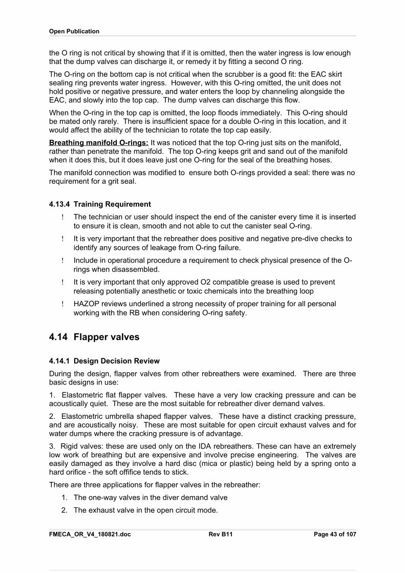
Open Publication
the O ring is not critical by showing that if it is omitted, then the water ingress is low enough that the dump valves can discharge it, or remedy it by fitting a second O ring.
The O-ring on the bottom cap is not critical when the scrubber is a good fit: the EAC skirt sealing ring prevents water ingress. However, with this O-ring omitted, the unit does not hold positive or negative pressure, and water enters the loop by channeling alongside the EAC, and slowly into the top cap. The dump valves can discharge this flow.
When the O-ring in the top cap is omitted, the loop floods immediately. This O-ring should be mated only rarely. There is insufficient space for a double O-ring in this location, and it would affect the ability of the technician to rotate the top cap easily.
Breathing manifold O-rings: It was noticed that the top O-ring just sits on the manifold, rather than penetrate the manifold. The top O-ring keeps grit and sand out of the manifold when it does this, but it does leave just one O-ring for the seal of the breathing hoses.
The manifold connection was modified to ensure both O-rings provided a seal: there was norequirement for a grit seal.
4.13.4 Training Requirement
The technician or user should inspect the end of the canister every time it is insertedto ensure it is clean, smooth and not able to cut the canister seal O-ring.
It is very important that the rebreather does positive and negative pre-dive checks to identify any sources of leakage from O-ring failure.
Include in operational procedure a requirement to check physical presence of the O-rings when disassembled.
It is very important that only approved O2 compatible grease is used to prevent releasing potentially anesthetic or toxic chemicals into the breathing loop
HAZOP reviews underlined a strong necessity of proper training for all personal working with the RB when considering O-ring safety.
4.14 Flapper valves
4.14.1 Design Decision Review
During the design, flapper valves from other rebreathers were examined. There are threebasic designs in use:
1. Elastometric flat flapper valves. These have a very low cracking pressure and can beacoustically quiet. These are the most suitable for rebreather diver demand valves.
2. Elastometric umbrella shaped flapper valves. These have a distinct cracking pressure,and are acoustically noisy. These are most suitable for open circuit exhaust valves and forwater dumps where the cracking pressure is of advantage.
3. Rigid valves: these are used only on the IDA rebreathers. These can have an extremelylow work of breathing but are expensive and involve precise engineering. The valves areeasily damaged as they involve a hard disc (mica or plastic) being held by a spring onto ahard orifice - the soft offifice tends to stick.
There are three applications for flapper valves in the rebreather:
1. The one-way valves in the diver demand valve
2. The exhaust valve in the open circuit mode.
FMECA_OR_V4_180821.doc Rev B11 Page 43 of 107
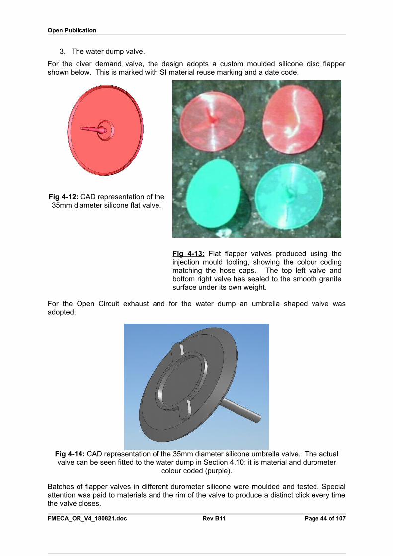
Open Publication
3. The water dump valve.
For the diver demand valve, the design adopts a custom moulded silicone disc flappershown below. This is marked with SI material reuse marking and a date code.
Fig 4 - 12 : CAD representation of the35mm diameter silicone flat valve.
Fig 4 - 13 : Flat flapper valves produced using theinjection mould tooling, showing the colour codingmatching the hose caps. The top left valve andbottom right valve has sealed to the smooth granitesurface under its own weight.
For the Open Circuit exhaust and for the water dump an umbrella shaped valve wasadopted.
Fig 4 - 14 : CAD representation of the 35mm diameter silicone umbrella valve. The actualvalve can be seen fitted to the water dump in Section 4.10: it is material and durometer
colour coded (purple).
Batches of flapper valves in different durometer silicone were moulded and tested. Specialattention was paid to materials and the rim of the valve to produce a distinct click every timethe valve closes.
FMECA_OR_V4_180821.doc Rev B11 Page 44 of 107
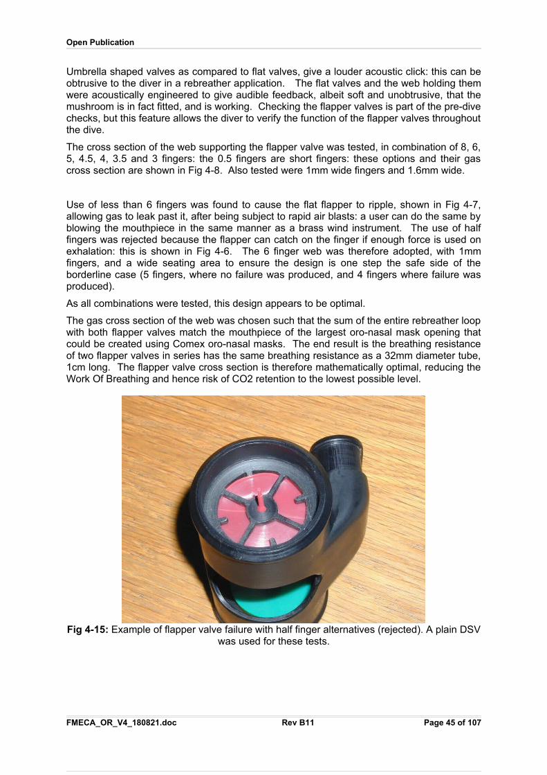
Open Publication
Umbrella shaped valves as compared to flat valves, give a louder acoustic click: this can beobtrusive to the diver in a rebreather application. The flat valves and the web holding themwere acoustically engineered to give audible feedback, albeit soft and unobtrusive, that themushroom is in fact fitted, and is working. Checking the flapper valves is part of the pre-divechecks, but this feature allows the diver to verify the function of the flapper valves throughoutthe dive.
The cross section of the web supporting the flapper valve was tested, in combination of 8, 6,5, 4.5, 4, 3.5 and 3 fingers: the 0.5 fingers are short fingers: these options and their gascross section are shown in Fig 4-8. Also tested were 1mm wide fingers and 1.6mm wide.
Use of less than 6 fingers was found to cause the flat flapper to ripple, shown in Fig 4-7,allowing gas to leak past it, after being subject to rapid air blasts: a user can do the same byblowing the mouthpiece in the same manner as a brass wind instrument. The use of halffingers was rejected because the flapper can catch on the finger if enough force is used onexhalation: this is shown in Fig 4-6. The 6 finger web was therefore adopted, with 1mmfingers, and a wide seating area to ensure the design is one step the safe side of theborderline case (5 fingers, where no failure was produced, and 4 fingers where failure wasproduced).
As all combinations were tested, this design appears to be optimal.
The gas cross section of the web was chosen such that the sum of the entire rebreather loopwith both flapper valves match the mouthpiece of the largest oro-nasal mask opening thatcould be created using Comex oro-nasal masks. The end result is the breathing resistanceof two flapper valves in series has the same breathing resistance as a 32mm diameter tube,1cm long. The flapper valve cross section is therefore mathematically optimal, reducing theWork Of Breathing and hence risk of CO2 retention to the lowest possible level.
Fig 4-15: Example of flapper valve failure with half finger alternatives (rejected). A plain DSVwas used for these tests.
FMECA_OR_V4_180821.doc Rev B11 Page 45 of 107
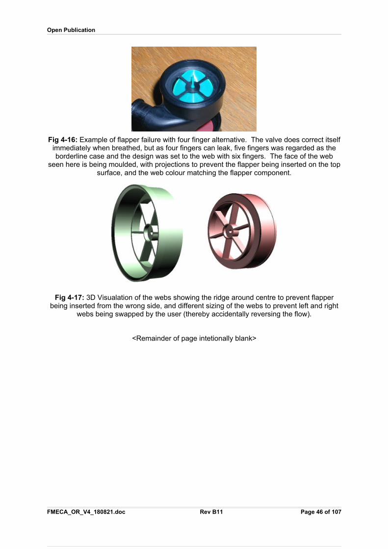
Open Publication
Fig 4-16: Example of flapper failure with four finger alternative. The valve does correct itselfimmediately when breathed, but as four fingers can leak, five fingers was regarded as theborderline case and the design was set to the web with six fingers. The face of the web
seen here is being moulded, with projections to prevent the flapper being inserted on the topsurface, and the web colour matching the flapper component.
Fig 4-17: 3D Visualation of the webs showing the ridge around centre to prevent flapperbeing inserted from the wrong side, and different sizing of the webs to prevent left and right
webs being swapped by the user (thereby accidentally reversing the flow).
<Remainder of page intetionally blank>
FMECA_OR_V4_180821.doc Rev B11 Page 46 of 107
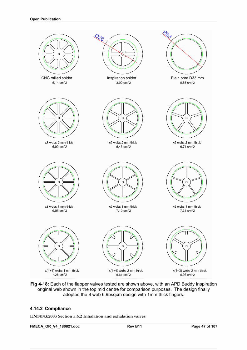
Open Publication
Fig 4-18: Each of the flapper valves tested are shown above, with an APD Buddy Inspirationoriginal web shown in the top mid centre for comparison purposes. The design finally
adopted the 8 web 6.95sqcm design with 1mm thick fingers.
4.14.2 Compliance
EN14143:2003 Section 5.6.2 Inhalation and exhalation valves
FMECA_OR_V4_180821.doc Rev B11 Page 47 of 107
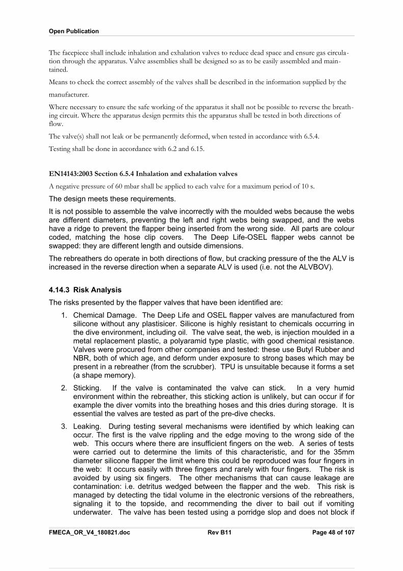
Open Publication
The facepiece shall include inhalation and exhalation valves to reduce dead space and ensure gas circula-tion through the apparatus. Valve assemblies shall be designed so as to be easily assembled and main-tained.
Means to check the correct assembly of the valves shall be described in the information supplied by the
manufacturer.
Where necessary to ensure the safe working of the apparatus it shall not be possible to reverse the breath-ing circuit. Where the apparatus design permits this the apparatus shall be tested in both directions of flow.
The valve(s) shall not leak or be permanently deformed, when tested in accordance with 6.5.4.
Testing shall be done in accordance with 6.2 and 6.15.
EN14143:2003 Section 6.5.4 Inhalation and exhalation valves
A negative pressure of 60 mbar shall be applied to each valve for a maximum period of 10 s.
The design meets these requirements.
It is not possible to assemble the valve incorrectly with the moulded webs because the websare different diameters, preventing the left and right webs being swapped, and the webshave a ridge to prevent the flapper being inserted from the wrong side. All parts are colourcoded, matching the hose clip covers. The Deep Life-OSEL flapper webs cannot beswapped: they are different length and outside dimensions.
The rebreathers do operate in both directions of flow, but cracking pressure of the the ALV isincreased in the reverse direction when a separate ALV is used (i.e. not the ALVBOV).
4.14.3 Risk Analysis
The risks presented by the flapper valves that have been identified are:
1. Chemical Damage. The Deep Life and OSEL flapper valves are manufactured fromsilicone without any plastisicer. Silicone is highly resistant to chemicals occurring inthe dive environment, including oil. The valve seat, the web, is injection moulded in ametal replacement plastic, a polyaramid type plastic, with good chemical resistance.Valves were procured from other companies and tested: these use Butyl Rubber andNBR, both of which age, and deform under exposure to strong bases which may bepresent in a rebreather (from the scrubber). TPU is unsuitable because it forms a set(a shape memory).
2. Sticking. If the valve is contaminated the valve can stick. In a very humidenvironment within the rebreather, this sticking action is unlikely, but can occur if forexample the diver vomits into the breathing hoses and this dries during storage. It isessential the valves are tested as part of the pre-dive checks.
3. Leaking. During testing several mechanisms were identified by which leaking canoccur. The first is the valve rippling and the edge moving to the wrong side of theweb. This occurs where there are insufficient fingers on the web. A series of testswere carried out to determine the limits of this characteristic, and for the 35mmdiameter silicone flapper the limit where this could be reproduced was four fingers inthe web: It occurs easily with three fingers and rarely with four fingers. The risk isavoided by using six fingers. The other mechanisms that can cause leakage arecontamination: i.e. detritus wedged between the flapper and the web. This risk ismanaged by detecting the tidal volume in the electronic versions of the rebreathers,signaling it to the topside, and recommending the diver to bail out if vomitingunderwater. The valve has been tested using a porridge slop and does not block if
FMECA_OR_V4_180821.doc Rev B11 Page 48 of 107
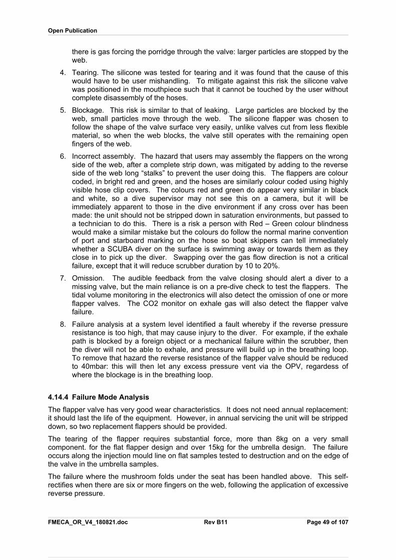
Open Publication
there is gas forcing the porridge through the valve: larger particles are stopped by theweb.
4. Tearing. The silicone was tested for tearing and it was found that the cause of thiswould have to be user mishandling. To mitigate against this risk the silicone valvewas positioned in the mouthpiece such that it cannot be touched by the user withoutcomplete disassembly of the hoses.
5. Blockage. This risk is similar to that of leaking. Large particles are blocked by theweb, small particles move through the web. The silicone flapper was chosen tofollow the shape of the valve surface very easily, unlike valves cut from less flexiblematerial, so when the web blocks, the valve still operates with the remaining openfingers of the web.
6. Incorrect assembly. The hazard that users may assembly the flappers on the wrongside of the web, after a complete strip down, was mitigated by adding to the reverseside of the web long “stalks” to prevent the user doing this. The flappers are colourcoded, in bright red and green, and the hoses are similarly colour coded using highlyvisible hose clip covers. The colours red and green do appear very similar in blackand white, so a dive supervisor may not see this on a camera, but it will beimmediately apparent to those in the dive environment if any cross over has beenmade: the unit should not be stripped down in saturation environments, but passed toa technician to do this. There is a risk a person with Red – Green colour blindnesswould make a similar mistake but the colours do follow the normal marine conventionof port and starboard marking on the hose so boat skippers can tell immediatelywhether a SCUBA diver on the surface is swimming away or towards them as theyclose in to pick up the diver. Swapping over the gas flow direction is not a criticalfailure, except that it will reduce scrubber duration by 10 to 20%.
7. Omission. The audible feedback from the valve closing should alert a diver to amissing valve, but the main reliance is on a pre-dive check to test the flappers. Thetidal volume monitoring in the electronics will also detect the omission of one or moreflapper valves. The CO2 monitor on exhale gas will also detect the flapper valvefailure.
8. Failure analysis at a system level identified a fault whereby if the reverse pressureresistance is too high, that may cause injury to the diver. For example, if the exhalepath is blocked by a foreign object or a mechanical failure within the scrubber, thenthe diver will not be able to exhale, and pressure will build up in the breathing loop.To remove that hazard the reverse resistance of the flapper valve should be reducedto 40mbar: this will then let any excess pressure vent via the OPV, regardess ofwhere the blockage is in the breathing loop.
4.14.4 Failure Mode Analysis
The flapper valve has very good wear characteristics. It does not need annual replacement:it should last the life of the equipment. However, in annual servicing the unit will be strippeddown, so two replacement flappers should be provided.
The tearing of the flapper requires substantial force, more than 8kg on a very smallcomponent. for the flat flapper design and over 15kg for the umbrella design. The failureoccurs along the injection mould line on flat samples tested to destruction and on the edge ofthe valve in the umbrella samples.
The failure where the mushroom folds under the seat has been handled above. This self-rectifies when there are six or more fingers on the web, following the application of excessivereverse pressure.
FMECA_OR_V4_180821.doc Rev B11 Page 49 of 107
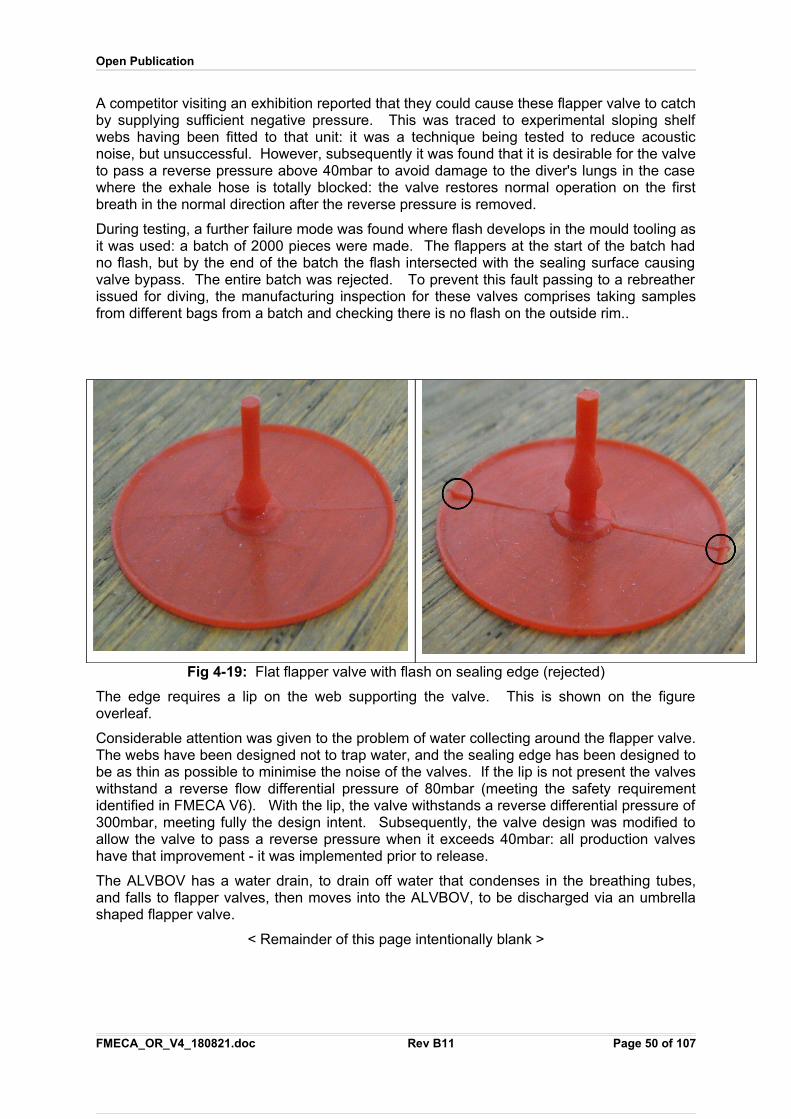
Open Publication
A competitor visiting an exhibition reported that they could cause these flapper valve to catchby supplying sufficient negative pressure. This was traced to experimental sloping shelfwebs having been fitted to that unit: it was a technique being tested to reduce acousticnoise, but unsuccessful. However, subsequently it was found that it is desirable for the valveto pass a reverse pressure above 40mbar to avoid damage to the diver's lungs in the casewhere the exhale hose is totally blocked: the valve restores normal operation on the firstbreath in the normal direction after the reverse pressure is removed.
During testing, a further failure mode was found where flash develops in the mould tooling asit was used: a batch of 2000 pieces were made. The flappers at the start of the batch hadno flash, but by the end of the batch the flash intersected with the sealing surface causingvalve bypass. The entire batch was rejected. To prevent this fault passing to a rebreatherissued for diving, the manufacturing inspection for these valves comprises taking samplesfrom different bags from a batch and checking there is no flash on the outside rim..
Fig 4-19: Flat flapper valve with flash on sealing edge (rejected)
The edge requires a lip on the web supporting the valve. This is shown on the figureoverleaf.
Considerable attention was given to the problem of water collecting around the flapper valve.The webs have been designed not to trap water, and the sealing edge has been designed tobe as thin as possible to minimise the noise of the valves. If the lip is not present the valveswithstand a reverse flow differential pressure of 80mbar (meeting the safety requirementidentified in FMECA V6). With the lip, the valve withstands a reverse differential pressure of300mbar, meeting fully the design intent. Subsequently, the valve design was modified toallow the valve to pass a reverse pressure when it exceeds 40mbar: all production valveshave that improvement - it was implemented prior to release.
The ALVBOV has a water drain, to drain off water that condenses in the breathing tubes,and falls to flapper valves, then moves into the ALVBOV, to be discharged via an umbrellashaped flapper valve.
< Remainder of this page intentionally blank >
FMECA_OR_V4_180821.doc Rev B11 Page 50 of 107
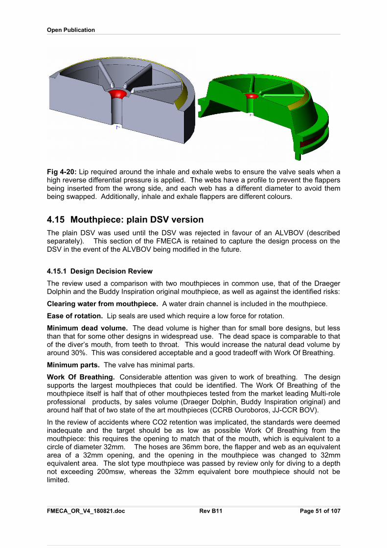
Open Publication
Fig 4-20: Lip required around the inhale and exhale webs to ensure the valve seals when ahigh reverse differential pressure is applied. The webs have a profile to prevent the flappersbeing inserted from the wrong side, and each web has a different diameter to avoid thembeing swapped. Additionally, inhale and exhale flappers are different colours.
4.15 Mouthpiece: plain DSV versionThe plain DSV was used until the DSV was rejected in favour of an ALVBOV (describedseparately). This section of the FMECA is retained to capture the design process on theDSV in the event of the ALVBOV being modified in the future.
4.15.1 Design Decision Review
The review used a comparison with two mouthpieces in common use, that of the DraegerDolphin and the Buddy Inspiration original mouthpiece, as well as against the identified risks:
Clearing water from mouthpiece. A water drain channel is included in the mouthpiece.
Ease of rotation. Lip seals are used which require a low force for rotation.
Minimum dead volume. The dead volume is higher than for small bore designs, but lessthan that for some other designs in widespread use. The dead space is comparable to thatof the diver’s mouth, from teeth to throat. This would increase the natural dead volume byaround 30%. This was considered acceptable and a good tradeoff with Work Of Breathing.
Minimum parts. The valve has minimal parts.
Work Of Breathing. Considerable attention was given to work of breathing. The designsupports the largest mouthpieces that could be identified. The Work Of Breathing of themouthpiece itself is half that of other mouthpieces tested from the market leading Multi-roleprofessional products, by sales volume (Draeger Dolphin, Buddy Inspiration original) andaround half that of two state of the art mouthpieces (CCRB Ouroboros, JJ-CCR BOV).
In the review of accidents where CO2 retention was implicated, the standards were deemedinadequate and the target should be as low as possible Work Of Breathing from themouthpiece: this requires the opening to match that of the mouth, which is equivalent to acircle of diameter 32mm. The hoses are 36mm bore, the flapper and web as an equivalentarea of a 32mm opening, and the opening in the mouthpiece was changed to 32mmequivalent area. The slot type mouthpiece was passed by review only for diving to a depthnot exceeding 200msw, whereas the 32mm equivalent bore mouthpiece should not belimited.
FMECA_OR_V4_180821.doc Rev B11 Page 51 of 107
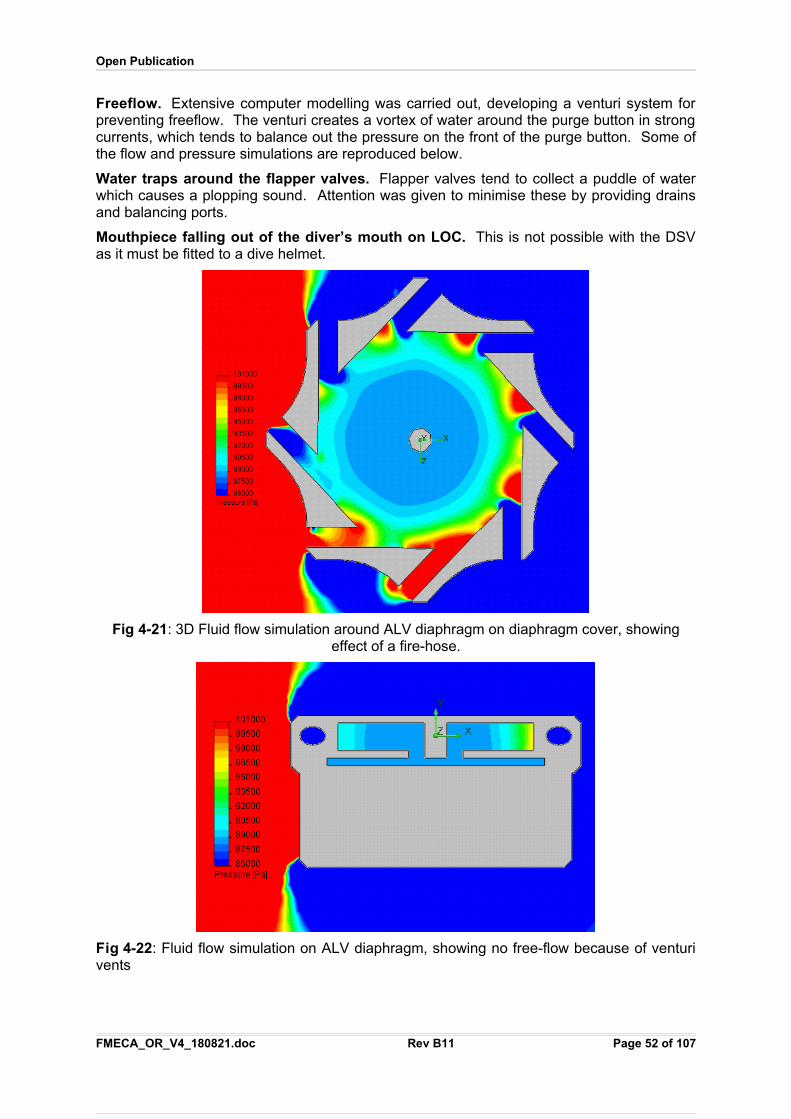
Open Publication
Freeflow. Extensive computer modelling was carried out, developing a venturi system forpreventing freeflow. The venturi creates a vortex of water around the purge button in strongcurrents, which tends to balance out the pressure on the front of the purge button. Some ofthe flow and pressure simulations are reproduced below.
Water traps around the flapper valves. Flapper valves tend to collect a puddle of waterwhich causes a plopping sound. Attention was given to minimise these by providing drainsand balancing ports.
Mouthpiece falling out of the diver’s mouth on LOC. This is not possible with the DSVas it must be fitted to a dive helmet.
Fig 4-21: 3D Fluid flow simulation around ALV diaphragm on diaphragm cover, showingeffect of a fire-hose.
Fig 4-22: Fluid flow simulation on ALV diaphragm, showing no free-flow because of venturivents
FMECA_OR_V4_180821.doc Rev B11 Page 52 of 107
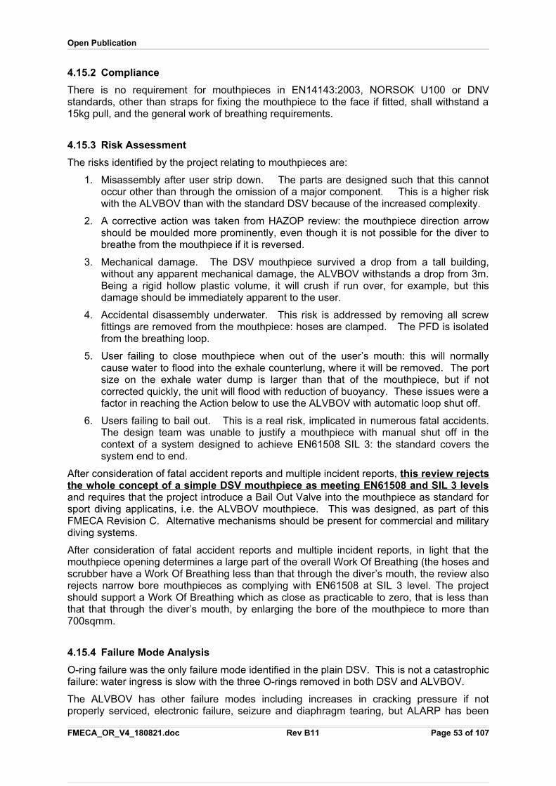
Open Publication
4.15.2 Compliance
There is no requirement for mouthpieces in EN14143:2003, NORSOK U100 or DNVstandards, other than straps for fixing the mouthpiece to the face if fitted, shall withstand a15kg pull, and the general work of breathing requirements.
4.15.3 Risk Assessment
The risks identified by the project relating to mouthpieces are:
1. Misassembly after user strip down. The parts are designed such that this cannotoccur other than through the omission of a major component. This is a higher riskwith the ALVBOV than with the standard DSV because of the increased complexity.
2. A corrective action was taken from HAZOP review: the mouthpiece direction arrowshould be moulded more prominently, even though it is not possible for the diver tobreathe from the mouthpiece if it is reversed.
3. Mechanical damage. The DSV mouthpiece survived a drop from a tall building,without any apparent mechanical damage, the ALVBOV withstands a drop from 3m.Being a rigid hollow plastic volume, it will crush if run over, for example, but thisdamage should be immediately apparent to the user.
4. Accidental disassembly underwater. This risk is addressed by removing all screwfittings are removed from the mouthpiece: hoses are clamped. The PFD is isolatedfrom the breathing loop.
5. User failing to close mouthpiece when out of the user’s mouth: this will normallycause water to flood into the exhale counterlung, where it will be removed. The portsize on the exhale water dump is larger than that of the mouthpiece, but if notcorrected quickly, the unit will flood with reduction of buoyancy. These issues were afactor in reaching the Action below to use the ALVBOV with automatic loop shut off.
6. Users failing to bail out. This is a real risk, implicated in numerous fatal accidents.The design team was unable to justify a mouthpiece with manual shut off in thecontext of a system designed to achieve EN61508 SIL 3: the standard covers thesystem end to end.
After consideration of fatal accident reports and multiple incident reports, this review rejectsthe whole concept of a simple DSV mouthpiece as meeting EN61508 and SIL 3 levelsand requires that the project introduce a Bail Out Valve into the mouthpiece as standard forsport diving applicatins, i.e. the ALVBOV mouthpiece. This was designed, as part of thisFMECA Revision C. Alternative mechanisms should be present for commercial and militarydiving systems.
After consideration of fatal accident reports and multiple incident reports, in light that themouthpiece opening determines a large part of the overall Work Of Breathing (the hoses andscrubber have a Work Of Breathing less than that through the diver’s mouth, the review alsorejects narrow bore mouthpieces as complying with EN61508 at SIL 3 level. The projectshould support a Work Of Breathing which as close as practicable to zero, that is less thanthat that through the diver’s mouth, by enlarging the bore of the mouthpiece to more than700sqmm.
4.15.4 Failure Mode Analysis
O-ring failure was the only failure mode identified in the plain DSV. This is not a catastrophicfailure: water ingress is slow with the three O-rings removed in both DSV and ALVBOV.
The ALVBOV has other failure modes including increases in cracking pressure if notproperly serviced, electronic failure, seizure and diaphragm tearing, but ALARP has been
FMECA_OR_V4_180821.doc Rev B11 Page 53 of 107
Open Publication
applied in taking on these risks whilst providing better protection to the user from the macrorisks of hypoxia and loop flooding than the DSV.
4.16 Mouthpiece: ALVBOV VersionThe ALVBOV provides a bail-out gas in the event of a detectable rebreather failure, andshuts off the breathing loop when the diver is either bailed out, or has the mouthpiece out ofhis mouth. The ALVBOV has replaced the DSW above.
4.16.1 Design Decision Review
The design had the following objectives:
1. Work of Breathing the same as for the DSV so there is no effect on the loop when theDSV is upgraded to the ALVBOV. The internal gas flow profile is identical betweenthe two valves: DSV and ALVBOV.
2. Two modes, and only two modes (no intermediate modes): Open Circuit and ClosedCircuit.
3. Neutral buoyancy in sea water
4. Manual bail out to Open Circuit meeting EN250 levels of performance
5. CCR DSV with a WOB under 0.6 J/L at 40msw with a 75 lpm RMV using air.
6. Avoidance of water trap around flapper valves
7. Means to remove water that collects in the mouthpiece.
8. Automatic bail out on removing the ALVBOV from the diver’s mouth.
9. Automatic bail out able to be activated electronically.
10. Peripheral Field Display attachment, provides voice and visual annunciation fordivers including those who are colour blind or sighted in only one eye.
11. Secure sealing that allows positive and negative pressure checks to be made out ofthe water.
12. Adjustable hose length.
13. Flapper valves are designed not to be swappable.
14. Breathing tube attachment not to use a clip attachment instead of a thread, to ensurethe tubes cannot be partially attached.
15. Anti-free flow on the front diaphragm, withstanding a fire hose directed at the front ofthe ALVBOV.
16. Regulator uses a standard Apeks second stage components for ease of servicing.
17. Cracking pressure adjusts automatically between Open Circuit and Closed Circuitmodes.
18. Rebreather loop is shut and sealed fully when the valve is in Open Circuit mode.
19. Freedom of movement required by EN14143:2003
20. Vision not obstructed: hoses are below the diver’s field of vision.
21. Hose connections that cannot be cross-threaded, or come apart accidentally.
The design meets these objectives.
FMECA_OR_V4_180821.doc Rev B11 Page 54 of 107
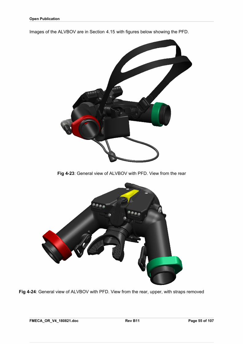
Open Publication
Images of the ALVBOV are in Section X4.15X with figures below showing the PFD.
Fig 4-23: General view of ALVBOV with PFD. View from the rear
Fig 4-24: General view of ALVBOV with PFD. View from the rear, upper, with straps removed
FMECA_OR_V4_180821.doc Rev B11 Page 55 of 107
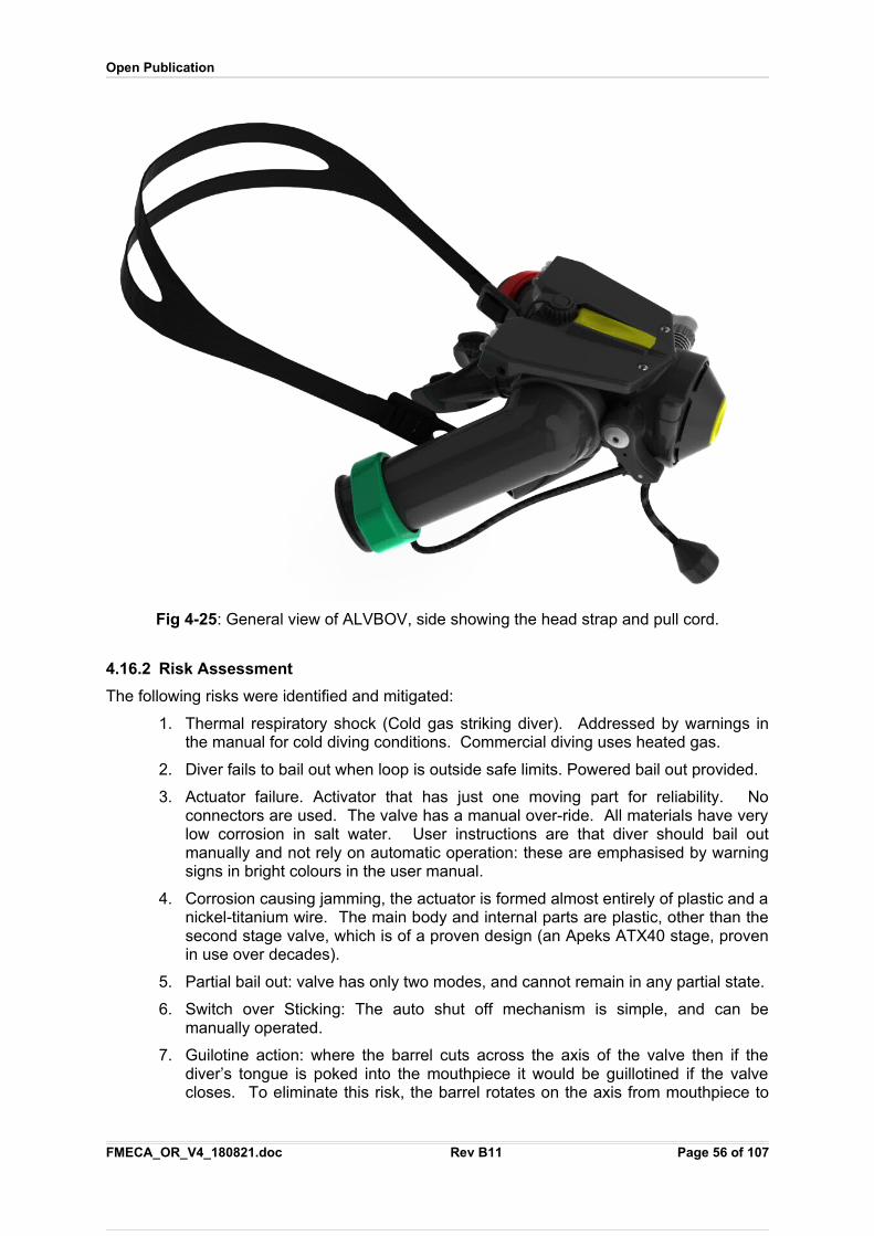
Open Publication
Fig 4-25: General view of ALVBOV, side showing the head strap and pull cord.
4.16.2 Risk Assessment
The following risks were identified and mitigated:
1. Thermal respiratory shock (Cold gas striking diver). Addressed by warnings inthe manual for cold diving conditions. Commercial diving uses heated gas.
2. Diver fails to bail out when loop is outside safe limits. Powered bail out provided.
3. Actuator failure. Activator that has just one moving part for reliability. Noconnectors are used. The valve has a manual over-ride. All materials have verylow corrosion in salt water. User instructions are that diver should bail outmanually and not rely on automatic operation: these are emphasised by warningsigns in bright colours in the user manual.
4. Corrosion causing jamming, the actuator is formed almost entirely of plastic and anickel-titanium wire. The main body and internal parts are plastic, other than thesecond stage valve, which is of a proven design (an Apeks ATX40 stage, provenin use over decades).
5. Partial bail out: valve has only two modes, and cannot remain in any partial state.
6. Switch over Sticking: The auto shut off mechanism is simple, and can bemanually operated.
7. Guilotine action: where the barrel cuts across the axis of the valve then if thediver’s tongue is poked into the mouthpiece it would be guillotined if the valvecloses. To eliminate this risk, the barrel rotates on the axis from mouthpiece to
FMECA_OR_V4_180821.doc Rev B11 Page 56 of 107
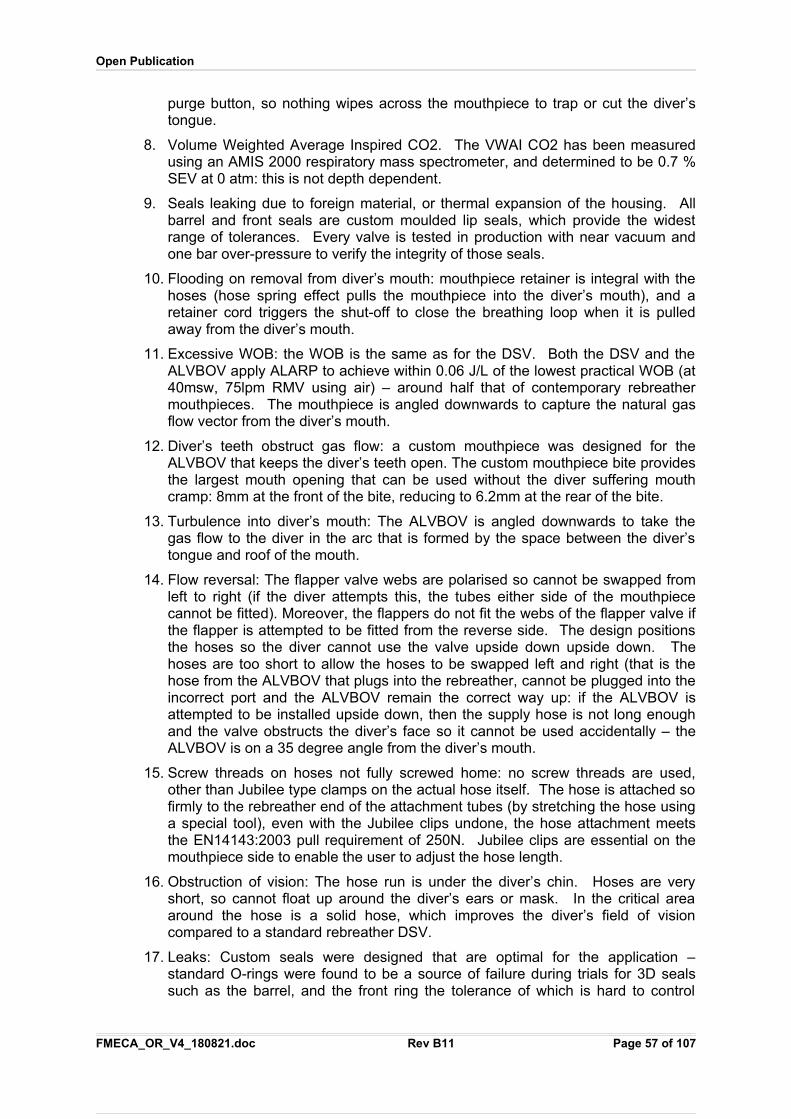
Open Publication
purge button, so nothing wipes across the mouthpiece to trap or cut the diver’stongue.
8. Volume Weighted Average Inspired CO2. The VWAI CO2 has been measuredusing an AMIS 2000 respiratory mass spectrometer, and determined to be 0.7 %SEV at 0 atm: this is not depth dependent.
9. Seals leaking due to foreign material, or thermal expansion of the housing. Allbarrel and front seals are custom moulded lip seals, which provide the widestrange of tolerances. Every valve is tested in production with near vacuum andone bar over-pressure to verify the integrity of those seals.
10. Flooding on removal from diver’s mouth: mouthpiece retainer is integral with thehoses (hose spring effect pulls the mouthpiece into the diver’s mouth), and aretainer cord triggers the shut-off to close the breathing loop when it is pulledaway from the diver’s mouth.
11. Excessive WOB: the WOB is the same as for the DSV. Both the DSV and theALVBOV apply ALARP to achieve within 0.06 J/L of the lowest practical WOB (at40msw, 75lpm RMV using air) – around half that of contemporary rebreathermouthpieces. The mouthpiece is angled downwards to capture the natural gasflow vector from the diver’s mouth.
12. Diver’s teeth obstruct gas flow: a custom mouthpiece was designed for theALVBOV that keeps the diver’s teeth open. The custom mouthpiece bite providesthe largest mouth opening that can be used without the diver suffering mouthcramp: 8mm at the front of the bite, reducing to 6.2mm at the rear of the bite.
13. Turbulence into diver’s mouth: The ALVBOV is angled downwards to take thegas flow to the diver in the arc that is formed by the space between the diver’stongue and roof of the mouth.
14. Flow reversal: The flapper valve webs are polarised so cannot be swapped fromleft to right (if the diver attempts this, the tubes either side of the mouthpiececannot be fitted). Moreover, the flappers do not fit the webs of the flapper valve ifthe flapper is attempted to be fitted from the reverse side. The design positionsthe hoses so the diver cannot use the valve upside down upside down. Thehoses are too short to allow the hoses to be swapped left and right (that is thehose from the ALVBOV that plugs into the rebreather, cannot be plugged into theincorrect port and the ALVBOV remain the correct way up: if the ALVBOV isattempted to be installed upside down, then the supply hose is not long enoughand the valve obstructs the diver’s face so it cannot be used accidentally – theALVBOV is on a 35 degree angle from the diver’s mouth.
15. Screw threads on hoses not fully screwed home: no screw threads are used,other than Jubilee type clamps on the actual hose itself. The hose is attached sofirmly to the rebreather end of the attachment tubes (by stretching the hose usinga special tool), even with the Jubilee clips undone, the hose attachment meetsthe EN14143:2003 pull requirement of 250N. Jubilee clips are essential on themouthpiece side to enable the user to adjust the hose length.
16. Obstruction of vision: The hose run is under the diver’s chin. Hoses are veryshort, so cannot float up around the diver’s ears or mask. In the critical areaaround the hose is a solid hose, which improves the diver’s field of visioncompared to a standard rebreather DSV.
17. Leaks: Custom seals were designed that are optimal for the application –standard O-rings were found to be a source of failure during trials for 3D sealssuch as the barrel, and the front ring the tolerance of which is hard to control
FMECA_OR_V4_180821.doc Rev B11 Page 57 of 107
Open Publication
sufficiently for a reliable O-ring seal. Custom lip seals are used instead, including3D seals.
18. Toxicity: All materials are non-toxic in normal use and have no significantallergenic reaction – no latex or rubber is used.
19. Weight: the overall weight was reduced to the lowest level consistent withachieving neutral buoyancy in sea water. The user manual contains warnings notto fold the hoses back so the ALVBOV can strike the diver.
20. Accidental activation: the status of the valve is immediately apparent to the diveras the front is marked and shows in the diver’s viewing field when in Open Circuitmode. Open Circuit is a fail safe condition: unit fails to fail safe. The activationtrigger is positioned such that it is not activated accidentally.
21. Flush access: the purge button on the front of the valve acts as a combined flushand purge.
22. Hose failure: three hoses on a conventional rebreather are combined into one –the manual make-up-gas inject, the ALV function and the bail-out function. Thefailure rate is therefore reduced by 3 P
rdP cube. Every hose is been tested at twelve
times the normal supply pressure (i.e. at 120 bar).
23. Water collection. The ALVBOV has a water drain: the function acts similarly to adiver blowing his nose. If the diver presses both sides of his “nose” and exhales,then water is drained out via the open circuit exhale valve.
24. Freeflow due to diaphragm folding: found to be a problem during unmanned andmanned tests with some types of open circuit diaphragm, causing slight oversupply of gas. Custom diaphragm moulded to avoid this which do not fold.
25. Freezing: the second stage valve has the same warming fins as on Apeks iceregulators. The valve is further warmed by being in the rebreather loop.
26. Incorrect cracking pressure: the valve has only a single adjustment point (foropen circuit cracking pressure) using the same method as used for Apeks highperformance diving second stages. The increase in cracking pressure forrebreather use, as an ALV, requires the spring in the valve to be within a rangethat is tightly controlled. The cracking pressure of every valve is measured inproduction using a breathing machine.
27. Diver inattention: if the diver does not request his PPO2 within sufficient intervalsto keep the maximum deviation of the PPO2 that could occur to be less than 0.05atm (regardless of whether this actually occurred), then the diver is warned. Ifthe deviation exceeds 0.5 atm, the diver is bailed out. The diver is also bailed outif the rebreather loop does not contain a safe gas (PPO2 outside safe limits,Exhaled PPCO2, PPN2 > EAD of 40msw, or loop flooded).
28. Partially sighted diver: divers with a sight impediment in one eye can chose left orright sided viewing from the PFD. One one side of the PFD is active. Selectionis by a USB utility.
29. Hose fittings and connections withstand a 100kg load.
30. Hose fittings cannot come off while the ALVBOV is in use: it comprises a clip thatcan obly be removed when the hoses are in the opposite direction to themouthpiece – this cannot occur when the diver is using the ALVBOV.
31. Colour blind diver: pulse duration and colours are chosen to enable commoncolour blindness conditions to be tolerated. Voice annunciation is used inaddition.
FMECA_OR_V4_180821.doc Rev B11 Page 58 of 107
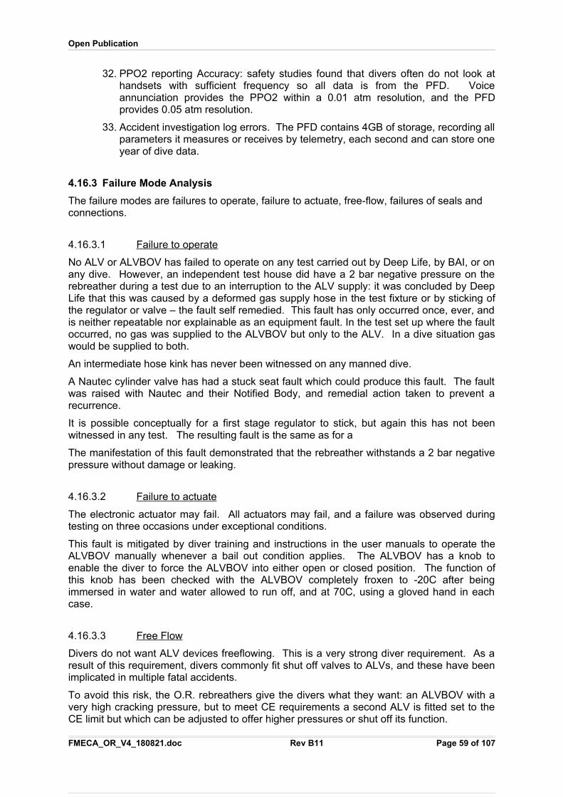
Open Publication
32. PPO2 reporting Accuracy: safety studies found that divers often do not look athandsets with sufficient frequency so all data is from the PFD. Voiceannunciation provides the PPO2 within a 0.01 atm resolution, and the PFDprovides 0.05 atm resolution.
33. Accident investigation log errors. The PFD contains 4GB of storage, recording allparameters it measures or receives by telemetry, each second and can store oneyear of dive data.
4.16.3 Failure Mode Analysis
The failure modes are failures to operate, failure to actuate, free-flow, failures of seals and connections.
4.16.3.1 Failure to operate
No ALV or ALVBOV has failed to operate on any test carried out by Deep Life, by BAI, or onany dive. However, an independent test house did have a 2 bar negative pressure on therebreather during a test due to an interruption to the ALV supply: it was concluded by DeepLife that this was caused by a deformed gas supply hose in the test fixture or by sticking ofthe regulator or valve – the fault self remedied. This fault has only occurred once, ever, andis neither repeatable nor explainable as an equipment fault. In the test set up where the faultoccurred, no gas was supplied to the ALVBOV but only to the ALV. In a dive situation gaswould be supplied to both.
An intermediate hose kink has never been witnessed on any manned dive.
A Nautec cylinder valve has had a stuck seat fault which could produce this fault. The faultwas raised with Nautec and their Notified Body, and remedial action taken to prevent arecurrence.
It is possible conceptually for a first stage regulator to stick, but again this has not beenwitnessed in any test. The resulting fault is the same as for a
The manifestation of this fault demonstrated that the rebreather withstands a 2 bar negativepressure without damage or leaking.
4.16.3.2 Failure to actuate
The electronic actuator may fail. All actuators may fail, and a failure was observed duringtesting on three occasions under exceptional conditions.
This fault is mitigated by diver training and instructions in the user manuals to operate theALVBOV manually whenever a bail out condition applies. The ALVBOV has a knob toenable the diver to force the ALVBOV into either open or closed position. The function ofthis knob has been checked with the ALVBOV completely froxen to -20C after beingimmersed in water and water allowed to run off, and at 70C, using a gloved hand in eachcase.
4.16.3.3 Free Flow
Divers do not want ALV devices freeflowing. This is a very strong diver requirement. As aresult of this requirement, divers commonly fit shut off valves to ALVs, and these have beenimplicated in multiple fatal accidents.
To avoid this risk, the O.R. rebreathers give the divers what they want: an ALVBOV with avery high cracking pressure, but to meet CE requirements a second ALV is fitted set to theCE limit but which can be adjusted to offer higher pressures or shut off its function.
FMECA_OR_V4_180821.doc Rev B11 Page 59 of 107
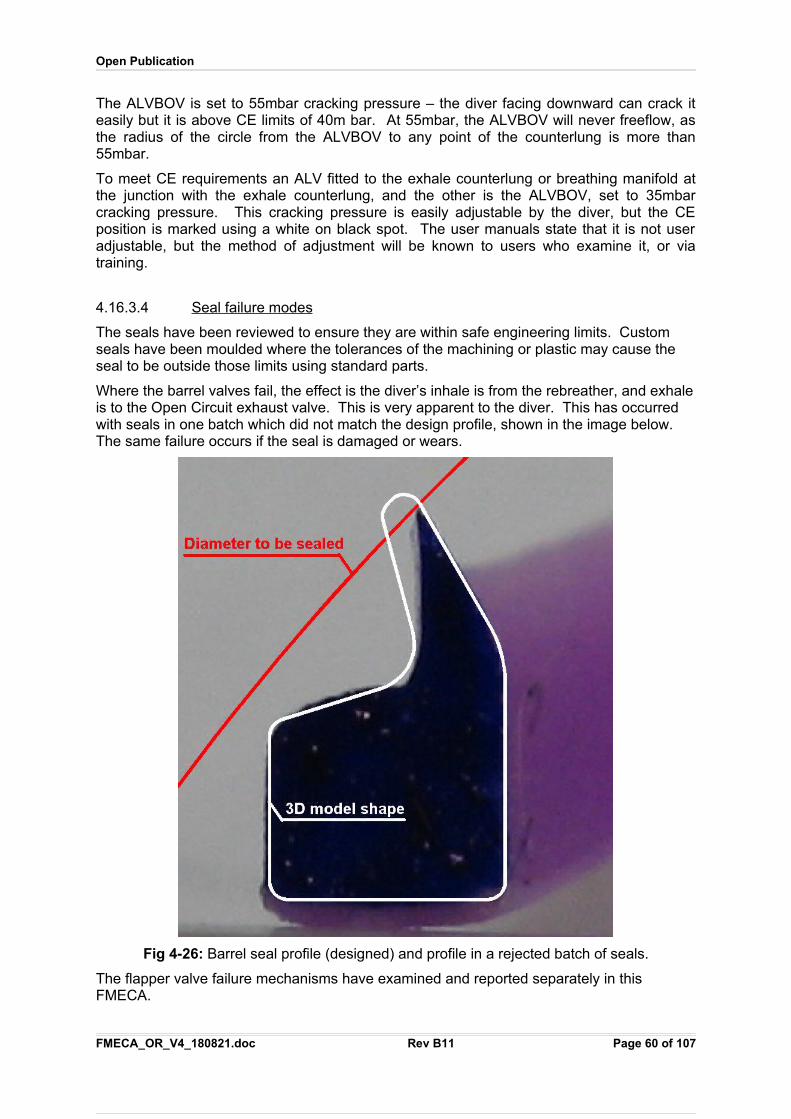
Open Publication
The ALVBOV is set to 55mbar cracking pressure – the diver facing downward can crack iteasily but it is above CE limits of 40m bar. At 55mbar, the ALVBOV will never freeflow, asthe radius of the circle from the ALVBOV to any point of the counterlung is more than55mbar.
To meet CE requirements an ALV fitted to the exhale counterlung or breathing manifold atthe junction with the exhale counterlung, and the other is the ALVBOV, set to 35mbarcracking pressure. This cracking pressure is easily adjustable by the diver, but the CEposition is marked using a white on black spot. The user manuals state that it is not useradjustable, but the method of adjustment will be known to users who examine it, or viatraining.
4.16.3.4 Seal failure modes
The seals have been reviewed to ensure they are within safe engineering limits. Custom seals have been moulded where the tolerances of the machining or plastic may cause the seal to be outside those limits using standard parts.
Where the barrel valves fail, the effect is the diver’s inhale is from the rebreather, and exhaleis to the Open Circuit exhaust valve. This is very apparent to the diver. This has occurred with seals in one batch which did not match the design profile, shown in the image below. The same failure occurs if the seal is damaged or wears.
Fig 4-26: Barrel seal profile (designed) and profile in a rejected batch of seals.
The flapper valve failure mechanisms have examined and reported separately in this FMECA.
FMECA_OR_V4_180821.doc Rev B11 Page 60 of 107
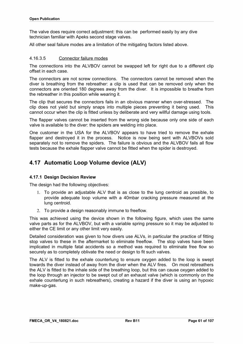
Open Publication
The valve does require correct adjustment: this can be performed easily by any dive technician familiar with Apeks second stage valves.
All other seal failure modes are a limitation of the mitigating factors listed above.
4.16.3.5 Connector failure modes
The connections into the ALVBOV cannot be swapped left for right due to a different clipoffset in each case.
The connectors are not screw connections. The connectors cannot be removed when thediver is breathing from the rebreather: a clip is used that can be removed only when theconnectors are oriented 180 degrees away from the diver. It is impossible to breathe fromthe rebreather in this position while wearing it.
The clip that secures the connectors fails in an obvious manner when over-stressed. Theclip does not yield but simply snaps into multiple pieces preventing it being used. Thiscannot occur when the clip is fitted unless by deliberate and very willful damage using tools.
The flapper valves cannot be inserted from the wrong side because only one side of eachvalve is available to the diver: the spiders are welding into place.
One customer in the USA for the ALVBOV appears to have tried to remove the exhaleflapper and destroyed it in the process. Notice is now being sent with ALVBOVs soldseparately not to remove the spiders. The failure is obvious and the ALVBOV fails all flowtests because the exhale flapper valve cannot be fitted when the spider is destroyed.
4.17 Automatic Loop Volume device (ALV)
4.17.1 Design Decision Review
The design had the following objectives:
1. To provide an adjustable ALV that is as close to the lung centroid as possible, toprovide adequate loop volume with a 40mbar cracking pressure measured at thelung centroid.
2. To provide a design reasonably immune to freeflow.
This was achieved using the device shown in the following figure, which uses the samevalve parts as for the ALVBOV, but with a variable spring pressure so it may be adjusted toeither the CE limit or any other limit very easily.
Detailed consideration was given to how divers use ALVs, in particular the practice of fittingstop valves to these in the aftermarket to eliminate freeflow. The stop valves have beenimplicated in multiple fatal accidents so a method was required to eliminate free flow sosecurely as to completely oblivate the need or design to fit such valves.
The ALV is fitted to the exhale counterlung to ensure oxygen added to the loop is swepttowards the diver instead of away from the diver when the ALV fires. On most rebreathersthe ALV is fitted to the inhale side of the breathing loop, but this can cause oxygen added tothe loop through an injector to be swept out of an exhaust valve (which is commonly on theexhale counterlung in such rebreathers), creating a hazard if the diver is using an hypoxicmake-up-gas.
FMECA_OR_V4_180821.doc Rev B11 Page 61 of 107
Open Publication
Fig 4-27: Sectional view of ALV showing the very simple construction. The diaphragm andmost valve parts are common to the ALVBOV.
4.17.2 Risk Assessment
The following risks were identified and mitigated:
1. Freeflow.
2. Failure to operate.
4.17.3 Failure Mode Analysis
The failure modes are failures to operate and free-flow. Both are treated in the same manner as these risks under ALVBOV.
.
FMECA_OR_V4_180821.doc Rev B11 Page 62 of 107
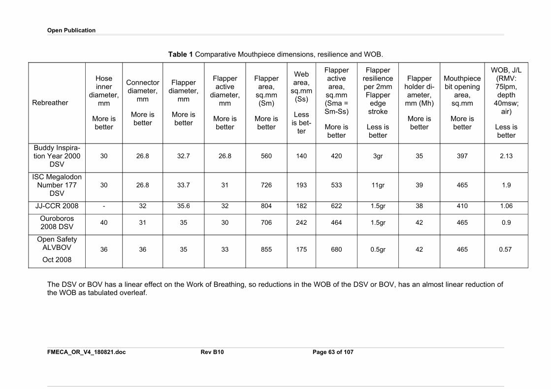
Open Publication
Table 1 Comparative Mouthpiece dimensions, resilience and WOB.
Rebreather
Hoseinner
diameter,mm
More isbetter
Connectordiameter,
mm
More isbetter
Flapperdiameter,
mm
More isbetter
Flapperactive
diameter,mm
More isbetter
Flapperarea,
sq.mm(Sm)
More isbetter
Webarea,
sq.mm(Ss)
Lessis bet-
ter
Flapperactivearea,
sq.mm(Sma =Sm-Ss)
More isbetter
Flapperresilienceper 2mmFlapper
edgestroke
Less isbetter
Flapperholder di-ameter,
mm (Mh)
More isbetter
Mouthpiecebit opening
area,sq.mm
More isbetter
WOB, J/L(RMV:75lpm,depth
40msw;air)
Less isbetter
Buddy Inspira-tion Year 2000
DSV30 26.8 32.7 26.8 560 140 420 3gr 35 397 2.13
ISC MegalodonNumber 177
DSV30 26.8 33.7 31 726 193 533 11gr 39 465 1.9
JJ-CCR 2008 - 32 35.6 32 804 182 622 1.5gr 38 410 1.06
Ouroboros2008 DSV
40 31 35 30 706 242 464 1.5gr 42 465 0.9
Open SafetyALVBOV
Oct 2008
36 36 35 33 855 175 680 0.5gr 42 465 0.57
The DSV or BOV has a linear effect on the Work of Breathing, so reductions in the WOB of the DSV or BOV, has an almost linear reduction ofthe WOB as tabulated overleaf.
FMECA_OR_V4_180821.doc Rev B10 Page 63 of 107
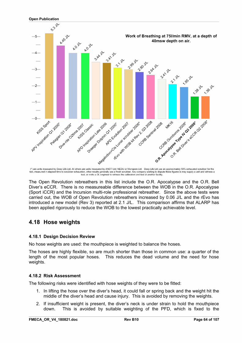
Open Publication
The Open Revolution rebreathers in this list include the O.R. Apocalypse and the O.R. BellDiver’s eCCR. There is no measureable difference between the WOB in the O.R. Apocalypse(Sport iCCR) and the Incursion multi-role professional rebreather. Since the above tests werecarried out, the WOB of Open Revolution rebreathers increased by 0.06 J/L and the rEvo hasintroduced a new model (Rev 3) reported at 2.1 J/L. This comparison affirms that ALARP hasbeen applied rigorously to reduce the WOB to the lowest practically achievable level.
4.18 Hose weights
4.18.1 Design Decision Review
No hose weights are used: the mouthpiece is weighted to balance the hoses.
The hoses are highly flexible, so are much shorter than those in common use: a quarter of thelength of the most popular hoses. This reduces the dead volume and the need for hoseweights.
4.18.2 Risk Assessment
The following risks were identified with hose weights of they were to be fitted:
1. In lifting the hose over the diver’s head, it could fall or spring back and the weight hit themiddle of the diver’s head and cause injury. This is avoided by removing the weights.
2. If insufficient weight is present, the diver’s neck is under strain to hold the mouthpiecedown. This is avoided by suitable weighting of the PFD, which is fixed to the
FMECA_OR_V4_180821.doc Rev B10 Page 64 of 107
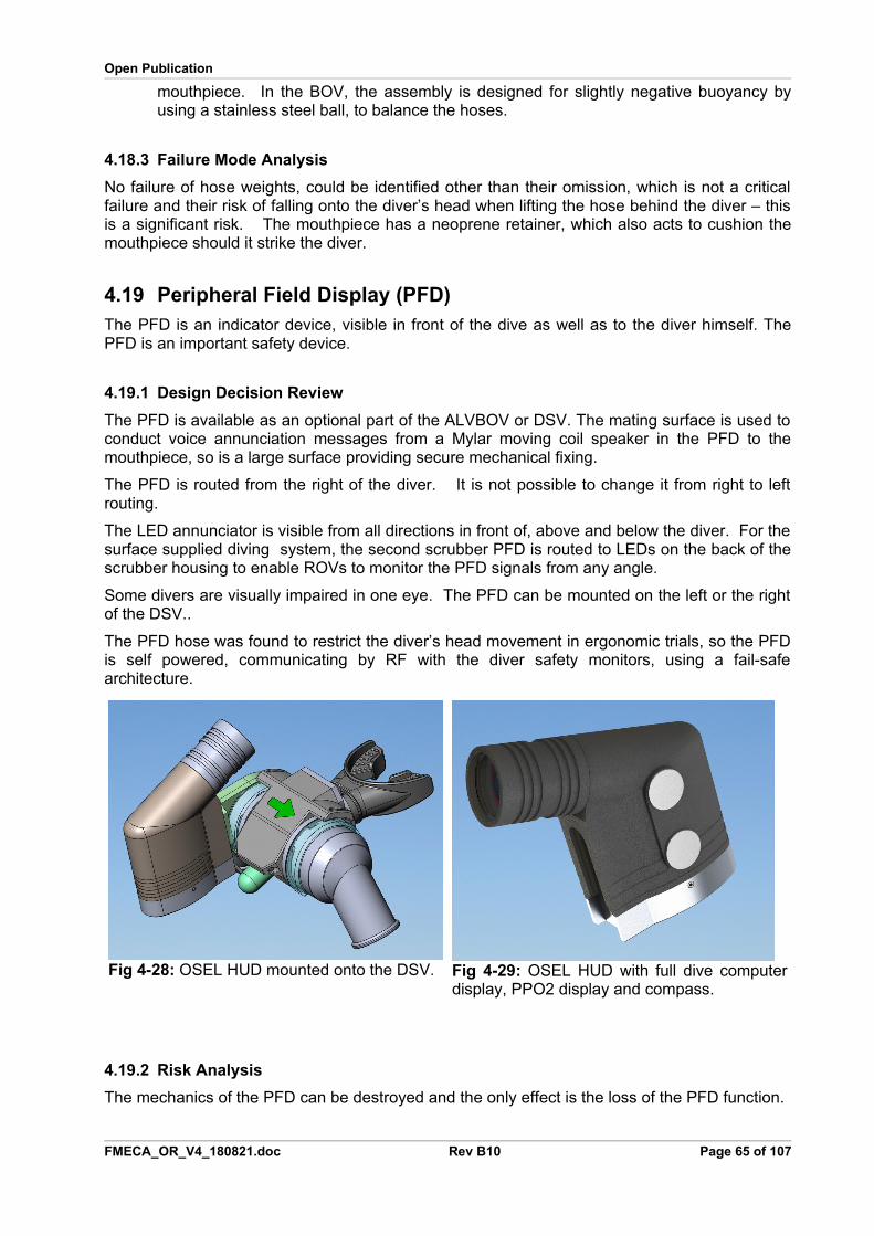
Open Publication
mouthpiece. In the BOV, the assembly is designed for slightly negative buoyancy byusing a stainless steel ball, to balance the hoses.
4.18.3 Failure Mode Analysis
No failure of hose weights, could be identified other than their omission, which is not a criticalfailure and their risk of falling onto the diver’s head when lifting the hose behind the diver – thisis a significant risk. The mouthpiece has a neoprene retainer, which also acts to cushion themouthpiece should it strike the diver.
4.19 Peripheral Field Display (PFD)The PFD is an indicator device, visible in front of the dive as well as to the diver himself. ThePFD is an important safety device.
4.19.1 Design Decision Review
The PFD is available as an optional part of the ALVBOV or DSV. The mating surface is used toconduct voice annunciation messages from a Mylar moving coil speaker in the PFD to themouthpiece, so is a large surface providing secure mechanical fixing.
The PFD is routed from the right of the diver. It is not possible to change it from right to leftrouting.
The LED annunciator is visible from all directions in front of, above and below the diver. For thesurface supplied diving system, the second scrubber PFD is routed to LEDs on the back of thescrubber housing to enable ROVs to monitor the PFD signals from any angle.
Some divers are visually impaired in one eye. The PFD can be mounted on the left or the rightof the DSV..
The PFD hose was found to restrict the diver’s head movement in ergonomic trials, so the PFDis self powered, communicating by RF with the diver safety monitors, using a fail-safearchitecture.
Fig 4-28: OSEL HUD mounted onto the DSV. Fig 4-29: OSEL HUD with full dive computerdisplay, PPO2 display and compass.
4.19.2 Risk Analysis
The mechanics of the PFD can be destroyed and the only effect is the loss of the PFD function.
FMECA_OR_V4_180821.doc Rev B10 Page 65 of 107
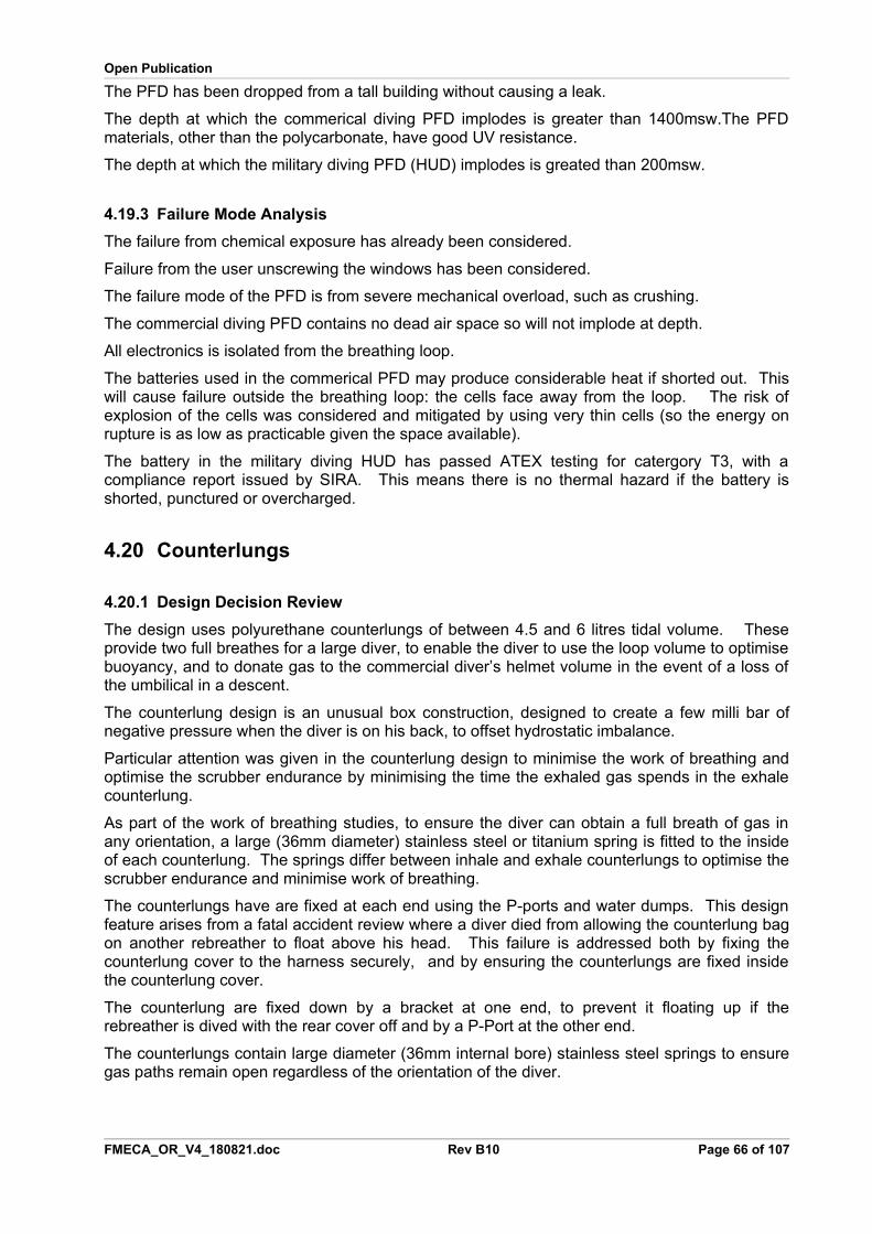
Open Publication
The PFD has been dropped from a tall building without causing a leak.
The depth at which the commerical diving PFD implodes is greater than 1400msw.The PFDmaterials, other than the polycarbonate, have good UV resistance.
The depth at which the military diving PFD (HUD) implodes is greated than 200msw.
4.19.3 Failure Mode Analysis
The failure from chemical exposure has already been considered.
Failure from the user unscrewing the windows has been considered.
The failure mode of the PFD is from severe mechanical overload, such as crushing.
The commercial diving PFD contains no dead air space so will not implode at depth.
All electronics is isolated from the breathing loop.
The batteries used in the commerical PFD may produce considerable heat if shorted out. Thiswill cause failure outside the breathing loop: the cells face away from the loop. The risk ofexplosion of the cells was considered and mitigated by using very thin cells (so the energy onrupture is as low as practicable given the space available).
The battery in the military diving HUD has passed ATEX testing for catergory T3, with acompliance report issued by SIRA. This means there is no thermal hazard if the battery isshorted, punctured or overcharged.
4.20 Counterlungs
4.20.1 Design Decision Review
The design uses polyurethane counterlungs of between 4.5 and 6 litres tidal volume. Theseprovide two full breathes for a large diver, to enable the diver to use the loop volume to optimisebuoyancy, and to donate gas to the commercial diver’s helmet volume in the event of a loss ofthe umbilical in a descent.
The counterlung design is an unusual box construction, designed to create a few milli bar ofnegative pressure when the diver is on his back, to offset hydrostatic imbalance.
Particular attention was given in the counterlung design to minimise the work of breathing andoptimise the scrubber endurance by minimising the time the exhaled gas spends in the exhalecounterlung.
As part of the work of breathing studies, to ensure the diver can obtain a full breath of gas inany orientation, a large (36mm diameter) stainless steel or titanium spring is fitted to the insideof each counterlung. The springs differ between inhale and exhale counterlungs to optimise thescrubber endurance and minimise work of breathing.
The counterlungs have are fixed at each end using the P-ports and water dumps. This designfeature arises from a fatal accident review where a diver died from allowing the counterlung bagon another rebreather to float above his head. This failure is addressed both by fixing thecounterlung cover to the harness securely, and by ensuring the counterlungs are fixed insidethe counterlung cover.
The counterlung are fixed down by a bracket at one end, to prevent it floating up if therebreather is dived with the rear cover off and by a P-Port at the other end.
The counterlungs contain large diameter (36mm internal bore) stainless steel springs to ensuregas paths remain open regardless of the orientation of the diver.
FMECA_OR_V4_180821.doc Rev B10 Page 66 of 107
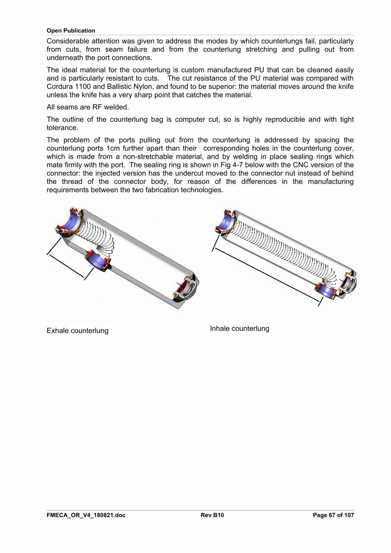
Open Publication
Considerable attention was given to address the modes by which counterlungs fail, particularlyfrom cuts, from seam failure and from the counterlung stretching and pulling out fromunderneath the port connections.
The ideal material for the counterlung is custom manufactured PU that can be cleaned easilyand is particularly resistant to cuts. The cut resistance of the PU material was compared withCordura 1100 and Ballistic Nylon, and found to be superior: the material moves around the knifeunless the knife has a very sharp point that catches the material.
All seams are RF welded.
The outline of the counterlung bag is computer cut, so is highly reproducible and with tighttolerance.
The problem of the ports pulling out from the counterlung is addressed by spacing thecounterlung ports 1cm further apart than their corresponding holes in the counterlung cover,which is made from a non-stretchable material, and by welding in place sealing rings whichmate firmly with the port. The sealing ring is shown in Fig 4-7 below with the CNC version of theconnector: the injected version has the undercut moved to the connector nut instead of behindthe thread of the connector body, for reason of the differences in the manufacturingrequirements between the two fabrication technologies.
Exhale counterlung Inhale counterlung
FMECA_OR_V4_180821.doc Rev B10 Page 67 of 107
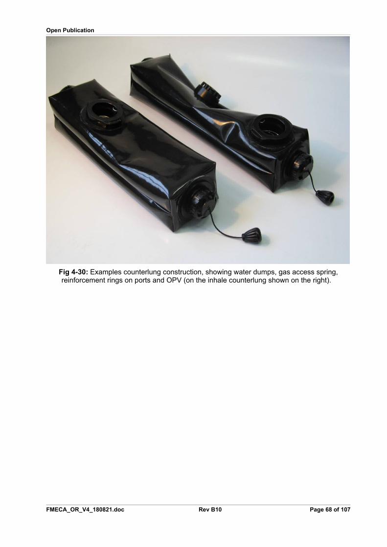
Open Publication
Fig 4-30: Examples counterlung construction, showing water dumps, gas access spring,reinforcement rings on ports and OPV (on the inhale counterlung shown on the right).
FMECA_OR_V4_180821.doc Rev B10 Page 68 of 107
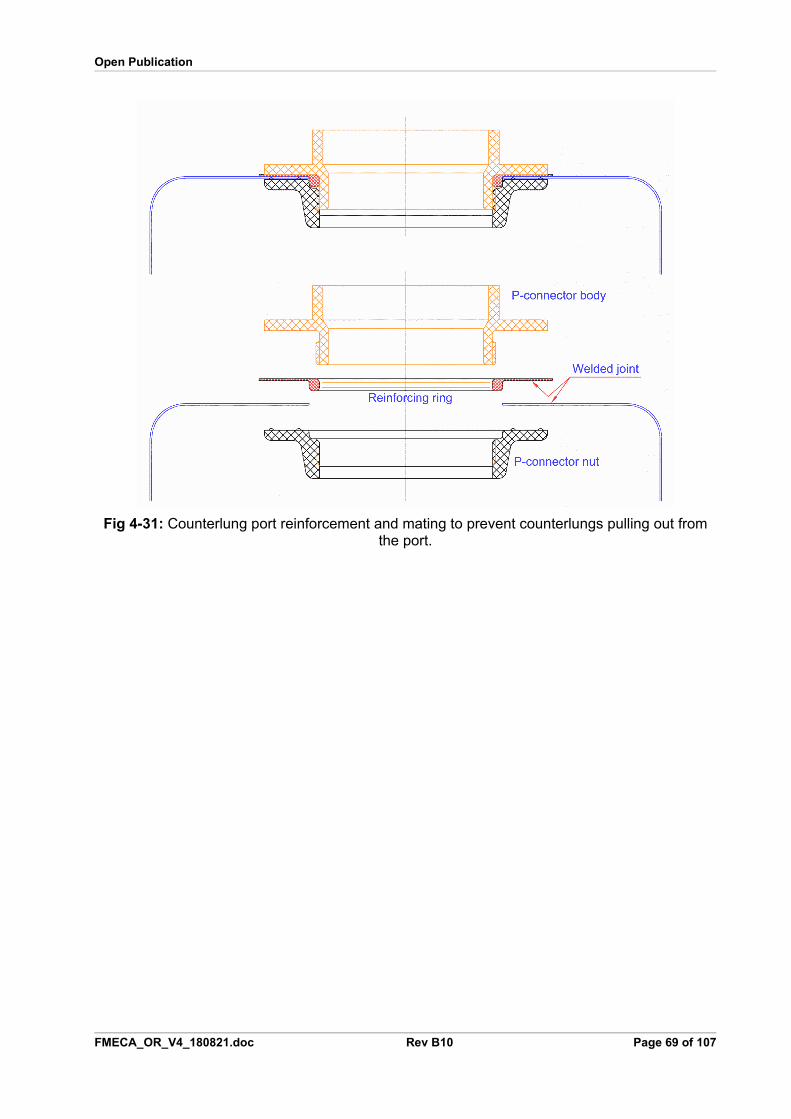
Open Publication
Fig 4-31: Counterlung port reinforcement and mating to prevent counterlungs pulling out fromthe port.
FMECA_OR_V4_180821.doc Rev B10 Page 69 of 107
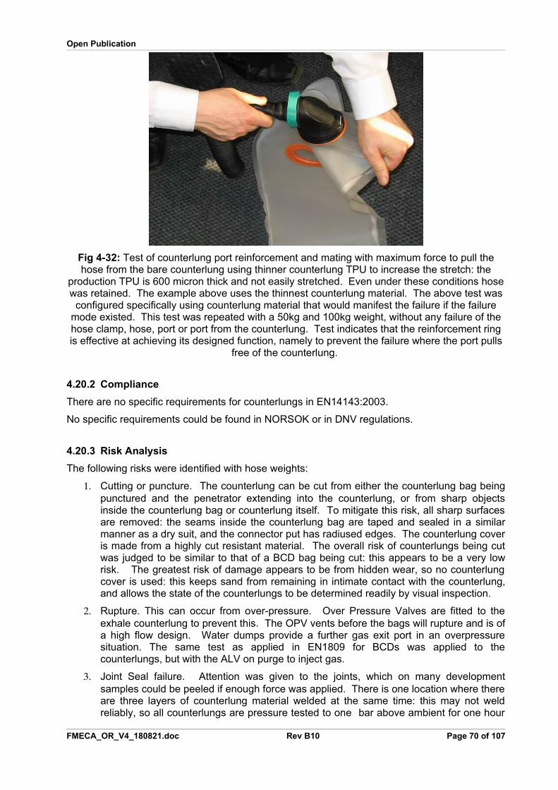
Open Publication
Fig 4-32: Test of counterlung port reinforcement and mating with maximum force to pull thehose from the bare counterlung using thinner counterlung TPU to increase the stretch: the
production TPU is 600 micron thick and not easily stretched. Even under these conditions hosewas retained. The example above uses the thinnest counterlung material. The above test was
configured specifically using counterlung material that would manifest the failure if the failuremode existed. This test was repeated with a 50kg and 100kg weight, without any failure of thehose clamp, hose, port or port from the counterlung. Test indicates that the reinforcement ringis effective at achieving its designed function, namely to prevent the failure where the port pulls
free of the counterlung.
4.20.2 Compliance
There are no specific requirements for counterlungs in EN14143:2003.
No specific requirements could be found in NORSOK or in DNV regulations.
4.20.3 Risk Analysis
The following risks were identified with hose weights:
1. Cutting or puncture. The counterlung can be cut from either the counterlung bag beingpunctured and the penetrator extending into the counterlung, or from sharp objectsinside the counterlung bag or counterlung itself. To mitigate this risk, all sharp surfacesare removed: the seams inside the counterlung bag are taped and sealed in a similarmanner as a dry suit, and the connector put has radiused edges. The counterlung coveris made from a highly cut resistant material. The overall risk of counterlungs being cutwas judged to be similar to that of a BCD bag being cut: this appears to be a very lowrisk. The greatest risk of damage appears to be from hidden wear, so no counterlungcover is used: this keeps sand from remaining in intimate contact with the counterlung,and allows the state of the counterlungs to be determined readily by visual inspection.
2. Rupture. This can occur from over-pressure. Over Pressure Valves are fitted to theexhale counterlung to prevent this. The OPV vents before the bags will rupture and is ofa high flow design. Water dumps provide a further gas exit port in an overpressuresituation. The same test as applied in EN1809 for BCDs was applied to thecounterlungs, but with the ALV on purge to inject gas.
3. Joint Seal failure. Attention was given to the joints, which on many developmentsamples could be peeled if enough force was applied. There is one location where thereare three layers of counterlung material welded at the same time: this may not weldreliably, so all counterlungs are pressure tested to one bar above ambient for one hour
FMECA_OR_V4_180821.doc Rev B10 Page 70 of 107
Open Publication
and in production a 25 cycle test is applied at one bar positive, to minus one bar (nearvacuum) for one minute per cycle.
Note: For each batch of counterlungs, a sample will be tested for peel strength to ensure it canwithstand 25kg of force on a corner applied at 90 degrees to the bag in a peeling action.
4. Separation from the ports. This was found to be a problem on all the contemporarycounterlungs that were examined unless the port was welded to the bag. There areinternet reports that a wider spacing between the port on the counterlung and the port onthe counterlung cover has not eliminated entirely these failures. The design avoids thisrisk by welding a ring to the bag which mates very securely with the port, as well asproviding the seal. This design improvement shown in XF i g 4 - 3 1X was injection moulded andtested, as shown in XFig 4-32X.
5. Chemical resistance. The PU material as well as the silicone material is highly resistantto oil, acids, caustic materials and solvents.
6. UV. Extensive field tests were carried out using white PU to highlight any UVdegradation. There is rapid surface degradation in UV, but it seems to stabilise after anhour in a tropical environment, and the counterlung remains serviceable. The black PUcontains carbon black which is an effective UV block and protective agent and nosignificant degradation was observed.
7. Bacterial growth. The counterlung is a smooth gloss black surface allowing forinspection to ensure nothing is growing in the bag. The material has a smooth innersurface aided sterilisation. The susceptibility of both counterlung materials, PU andsilicone, to contamination from bacteria, especially by Pseudomonas aeruginosa, wasbe checked researches from SINTEF Health Research with reference to earlier workthey had carried out using cell cultures.
8. Unwanted movement. The counterlungs are fixed down at each end.
4.20.4 Failure Mode Analysis
The failure mode of the counterlung is opening to the water, allowing water to invade thebreathing loop.
The probability of failure given the measures taken to mitigate risk is very low but probable.
The effect of a small failure would be to collect water in the exhale counterlung, where it wouldbe exhausted to the environment via the OPV.
The probability of a massive rupture is extremely low, but plausible.
The effect of a massive rupture would be for water to invade the scrubber canister where theflood would be detected by the electronics from the increase in pressure across the scrubberand the Auto Shut Off Valve operate. This prevents the effect of a massive failure of thecounterlungs from endangering the diver.
Any failure of the counterlung is detected by the positive and negative pressure tests duringdive preparation.
4.21 Counterlung Covers
4.21.1 Design Decision Review
For the breathing bags, tests were carried out using two-ply dry suit material: this is a laminatedfabric that has a supporting structure of 1000D or 1100 Cordura laminated with 5 mil of PU onboth sides: this is extremely tear and abrasion resistant and easy to clean. The counterlungcovers have stainless steel vents to enable water to drain from them and for air to escape at the
FMECA_OR_V4_180821.doc Rev B10 Page 71 of 107
Open Publication
start of a dive. These vents are on the inside surface to provide the maximum protection fromsharp objects.
The tests found that the breathing resistance of the two ply counterlungs was higher than forsingle ply, and that a single ply 600 to 800 micron thick PU would withstand both abrasiona dnknife attack better then the Cordura: the elasticity in the material allows it to flow around theknife instead of catching and cutting. Single ply CLs are adopted as a result of these tests.
4.21.2 Risk Analysis
1. UV. The counterlungs will be exposed to intensive UV on the decks of dive vessels. Bothcounterlung cover materials have excellent UV resistance. The material in black hassignificantly higher UV resistance than the material in any other colour.
2. Chemical. The counterlungs may be exposed to chemical contaminants. Thecounterlung cover materials are highly resistant to oil and other common contaminants.The commercial dive counterlung covers are easily washable, having a smooth surface.
3. Puncture. There is a risk that the counterlung cover will be punctured, especially if theequipment is used in an overhead environment or with underwater cutting tools. Theuse of 1000gm Cordura appears sufficient for recreational divers but the commercialdiver presents a concern, even with the two-ply cover: a commercial diver can shred adive suit on a single dive. It was found that the counterlung material itself is in fact moreresistant to cutting than 1000gm Cordura.
4. Separation from harness. A fatal accident has occurred where a Multi-role professionalrebreather diver failed to fix down the counterlungs properly, and they floated above thediver’s head during the dive. The increased Work Of Breathing caused CO2 retention,resulting in the diver losing consciousness.
5. The use of counterlung covers can trap grit, and the seams can create a rubbing spot inone location. The covers also increase the work of breathing.
4.21.3 Failure Mode Analysis
The failure mode of the counterlung covers not being fixed down results in a large increase inthe Work Of Breathing. Webbing able to maintain a one ton tensile load was used to preventthe counterlung covers failing in this manner.
The failure mode of the counterlung cover being punctured gives risk to a risk of the counterlungbeing punctured. The counterlung material appears to be more resistant to puncture than thecovers in tests even for ballistic nylon and Cordura covers.
The risks of separation, grit entrapement and increased work of breathing means that thecounterlung covers will not be used in back mounted counterlung configurations of therebreathers. However, they are used in hydrostatic tests to give a worst case, and the optionfor the project to adopt these in applications where grit is not an issue, such as in HAZMATrebreathers.
4.22 Scrubber Housing
4.22.1 Design Decision Review
There are two scrubber housings, samples of which were submitted as part of this review,shown in Fig 4-8 and 4-9 below.
The two scrubber designs are very similar, the main difference is one uses a twin scrubber withinternal gas return tube, while the other is a single scrubber. The scrubbers use MicroporeExtendAir Cartridges (EACs).
FMECA_OR_V4_180821.doc Rev B10 Page 72 of 107
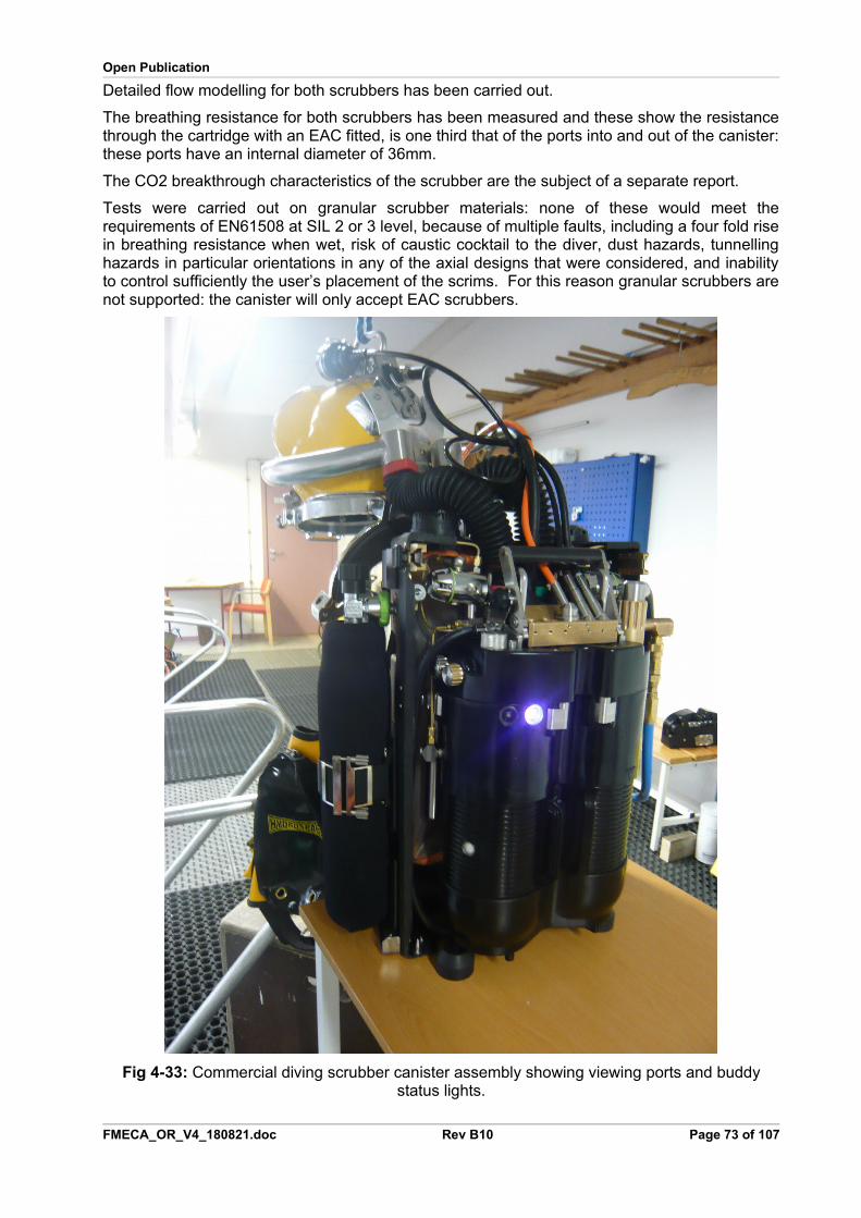
Open Publication
Detailed flow modelling for both scrubbers has been carried out.
The breathing resistance for both scrubbers has been measured and these show the resistancethrough the cartridge with an EAC fitted, is one third that of the ports into and out of the canister:these ports have an internal diameter of 36mm.
The CO2 breakthrough characteristics of the scrubber are the subject of a separate report.
Tests were carried out on granular scrubber materials: none of these would meet therequirements of EN61508 at SIL 2 or 3 level, because of multiple faults, including a four fold risein breathing resistance when wet, risk of caustic cocktail to the diver, dust hazards, tunnellinghazards in particular orientations in any of the axial designs that were considered, and inabilityto control sufficiently the user’s placement of the scrims. For this reason granular scrubbers arenot supported: the canister will only accept EAC scrubbers.
Fig 4-33: Commercial diving scrubber canister assembly showing viewing ports and buddystatus lights.
FMECA_OR_V4_180821.doc Rev B10 Page 73 of 107

Open Publication
Fig 4-34: Multi-role professional eCCR configuration showing the scrubber viewing port: thesame scrubber barrel is used on all units, and all contain the scrubber viewing port.
4.22.2 Risk Assessment
UV. The scrubber housing may be exposed to intense UV on the deck of dive vessels or wherearc welding is carried out. To mitigate this risk, all hard plastic parts are made from UV tolerantmaterials: Kynar, Black PU, Black ASA or a custom formulated PP depending on theapplication. All these materials have good UV characteristics.
Chemical Damage. All plastics used have good chemical resistance to the chemicals theequipment is likely to be exposed to, including oil.
Bacterial contamination. The canisters have smooth internal surfaces that are cleaned easily.The external surface is overmoulded for applications where ease of decontamination isimportant.
Mechanical Damage to canister. The canister is liable to damage from crushing. The pressureat which this occurs in excess of 200kg in each case. If there is a sudden shock load, such asa large person jumping on the canister when outside its caps, the canister shatters: this hasbeen confirmed in tests.
The canister has been tested with repeated drops from a height of 3m without damage.
Mechanical Damage to EAC. The EAC should be inspected for mechanical damage beforeinsertion. In a recreational dive environment this may be difficult to enforce. Failure is detectedby CO2 breakthrough. The first sample submitted for review, shown in Fig 4.8, had a very largeseal area on the bottom of the scrubber, with three parts sealing together: this was rejected as itcould be damaged easily in service. A replacement design sample was submitted with the longseal removed, and this was accepted. The scrubber seal was designed to accommodate up to7mm of damage to the sealing end of the cartridge, and generally accommodates 10mm ofdamage.
Incorrect threading. A very wide bayonet thread is used that is difficult to cross thread. Howeverit can be cross threaded, so the inner part of the barrel is being printed in a highlight colour (red)to make it obvious to the user of this is happening.
FMECA_OR_V4_180821.doc Rev B10 Page 74 of 107
Open Publication
Difficulty to release. Some scrubber designs are difficult to separate, causing users to damagethe mating surfaces using instruments to prise apart the scrubber. This risk is avoided by usinga bayonet fitting that forces the ends apart when it is rotated.Accidental disassembly. The commercial dive unit has two canisters which must rotate inopposite directions simultaneously to release the scrubber end. The simultaneous action isreinforced using Velcro as a gear between the two scrubbers. The single scrubber unit has theend caps plugging directly into the counterlungs, and this prevents the end caps from moving.
Failure to fit the scrubber. A scrubber viewing port is on every scrubber barrel: this showsclearly whether or not a scrubber is fitted.
To prevent divers doing too many dives on a scrubber, divers doing dives of less than 2 hoursduration are instructed to rotate the scrubber on its axis by 180 degrees between dives, with theEAC seam towards the back for the first dive – so it will be towards the front after the seconddive, so must be discarded. This is in addition to the usual recommendation to log scrubbertime on duct tape applied to the scrubber cap as a waterproof label.
4.22.3 Failure Mode Analysis
If the canister is breached, then water will ingress into the system.
The system will fail positive and negative pressure pre-dive checks. In service, the water will build up in the scrubber and if not drained to the exhale counterlung and dumped, will cause theEAC overpressure flood warning to be activated.
The case of damage to the electronics chamber at the end of the scrubber is considered separately.
4.23 Scrubber attachment
4.23.1 Design Decision Review
The scrubbers in the eCCR configuraitons are attached using triangulated suspension mountsto absorb the peak shocks, to prevent damage to the oxygen sensors in a working environment.The suspensions mounts are fixed by screws to the rebreather housing in an area where theplastic is thickest.
The iCCR is a dump canister and there is no material safety hazard from fitting it upside down,however, the clamping arrangement enforces the thinner of the two caps to be upright: thelarger cap would interfere with the trim weights.
4.23.2 Risk Assessment
The triangulated mounts make it impossible to fit the eCCR scrubbers upside down: this isimportant for the eCCR because the flow through the scrubber to the sensors must be in thedesigned direction.
The iCCR scrubber is attached using a folded plate. The plate has a radius of more than 1mmon all edges, so does not present a cutting risk to the counterlungs: in normal use the bracketdoes not touch the counterlungs, but can do if the scrubber is removed.
4.23.3 Failure Modes
Sufficient mechanical shock will pull the mounts from the plastic housing. The shock required isvery high: more than a 3m fall. The failure will be apparent to the user, who should return the
FMECA_OR_V4_180821.doc Rev B13 Page 75 of 107
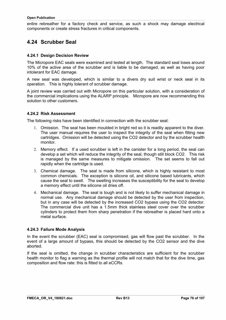
Open Publication
entire rebreather for a factory check and service, as such a shock may damage electricalcomponents or create stress fractures in critical components.
4.24 Scrubber Seal
4.24.1 Design Decision Review
The Micropore EAC seals were examined and tested at length. The standard seal loses around10% of the active area of the scrubber and is liable to be damaged, as well as having poorintolerant for EAC damage.
A new seal was developed, which is similar to a divers dry suit wrist or neck seal in itsoperation. This is highly tolerant of scrubber damage.
A joint review was carried out with Micropore on this particular solution, with a consideration ofthe commercial implications using the ALARP principle. Micropore are now recommending thissolution to other customers.
4.24.2 Risk Assessment
The following risks have been identified in connection with the scrubber seal:
1. Omission. The seal has been moulded in bright red so it is readily apparent to the diver.The user manual requires the user to inspect the integrity of the seal when fitting newcartridges. Omission will be detected using the CO2 detector and by the scrubber healthmonitor.
2. Memory effect. If a used scrubber is left in the canister for a long period, the seal candevelop a set which will reduce the integrity of the seal, though still block CO2. This riskis managed by the same measures to mitigate omission. The set seems to fall outrapidly when the cartridge is used.
3. Chemical damage. The seal is made from silicone, which is highly resistant to mostcommon chemicals. The exception is silicone oil, and silicone based lubricants, whichcause the seal to swell. The swelling increases the susceptibility for the seal to developa memory effect until the silicone oil dries off.
4. Mechanical damage. The seal is tough and is not likely to suffer mechanical damage innormal use. Any mechanical damage should be detected by the user from inspection,but in any case will be detected by the increased CO2 bypass using the CO2 detector.The commercial dive unit has a 1.5mm thick stainless steel cover over the scrubbercylinders to protect them from sharp penetration if the rebreather is placed hard onto ametal surface.
4.24.3 Failure Mode Analysis
In the event the scrubber (EAC) seal is compromised, gas will flow past the scrubber. In theevent of a large amount of bypass, this should be detected by the CO2 sensor and the diveaborted.
If the seal is omitted, the change in scrubber characteristics are sufficient for the scrubberhealth monitor to flag a warning as the thermal profile will not match that for the dive time, gascomposition and flow rate: this is fitted to all eCCRs.
FMECA_OR_V4_180821.doc Rev B13 Page 76 of 107
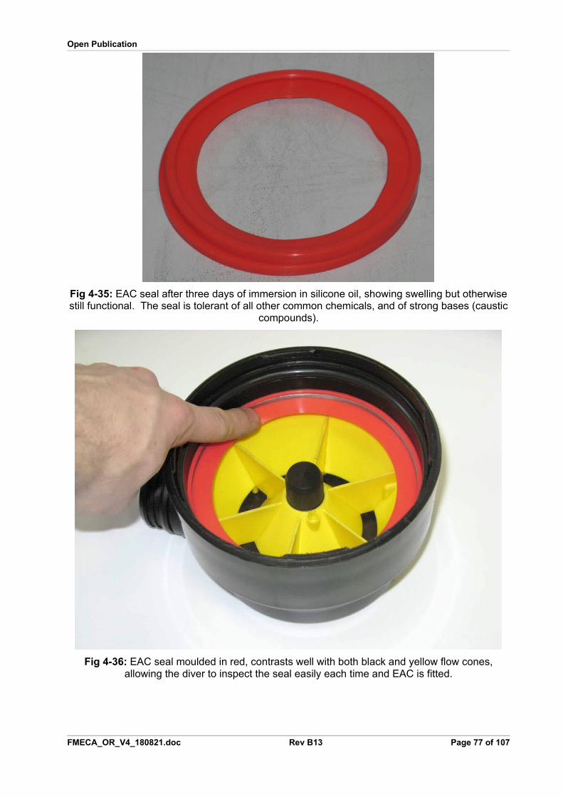
Open Publication
Fig 4-35: EAC seal after three days of immersion in silicone oil, showing swelling but otherwisestill functional. The seal is tolerant of all other common chemicals, and of strong bases (caustic
compounds).
Fig 4-36: EAC seal moulded in red, contrasts well with both black and yellow flow cones,allowing the diver to inspect the seal easily each time and EAC is fitted.
FMECA_OR_V4_180821.doc Rev B13 Page 77 of 107
Open Publication
4.25 Scrubber Housing Seal
4.25.1 Design Decision Review
The design team chose to adopt an existing, proven design rather than create a new seal. Theseal is the same as Micropore have used for five years with replacement scrubbers and inOptima, Azimuth and Draeger canister designs, except that the seal is changed to EPDM forimproved chemical resistance.
The twin scrubber configuration has an additional seal of the same type at the end of thestainless steel breathing tube that returns through the scrubber.
4.25.2 Risk Assessment
The following risks were identified in relation to the scrubber housing seal:
1. UV Damage. The part should not be exposed to intense UV, but this is likely if thescrubber canister is left open on the deck of a dive vessel or where arc welding is carriedout. The EPDM seal has good to excellent resistance to UV.
2. Mechanical Damage. The seal can be damaged in service. The EPDM seal has thebest mechanical properties of any of the common seal materials.
3. Incorrect assembly. The seal can be omitted by the user.
4.25.3 Failure Mode Analysis
Mechanical failure of the canister seal can not occur in service, only while the canister is open.Any damage to the seal is detected by positive and negative pressure checks that are enforcedby the electronics as part of the pre-dive checks.
Omission of a seal results in failure of pre-dive positive and negative pressure checks.
The seal is made from EPDM to provide the correct compliance that it also tough and unlikely tobe cut.
4.26 Flow Cones
4.26.1 Design Decision Review
The flow cones are the result of extensive computer flow modeling through the scrubber, toachieve an even flow despite obstructions and asymmetric ports into and out of the scrubber,and verified during scrubber endurance tests.
4.26.2 Risk Assessment
The following risks have been identified in relation to the flow cones.
1. UV or Chemical Damage. The flow cones are manufactured from Kynar or Black ASA.Both are highly resistant to UV and chemicals (including strong bases, to which they areexposed close to the scrubber).
2. Incorrect assembly. This risk is avoided by using a index line to ensure the flow cones fitinto place: if not in place it is obvious they are not in place.
3. Mechanical damage. The cones are hard to damage, and damage is apparent to theuser on fitting a new scrubber EAC. They are moulded from a contrasting colour to thebottom caps, Orange, to make any damage evident, and also to make it evident if thebottom scrubber locating pin is missing.
FMECA_OR_V4_180821.doc Rev B13 Page 78 of 107
Open Publication
4.26.3 Failure Mode Analysis
No failure mode specific to the flow cones has been identified, provided they are welded intoplace.
When the cones are clipped in place, it was found that users could snap off the locating pins:users feel the slight movement of the flow cone and assume that it rotates. It does not rotatebecause it modifies the gas flow asymmetrically to achieve an even flow through the scrubber.This failure mode is being addressed by adding additional tags to the cone and the end capmoulding. Unfortunately it is not possible to make the tabs thicker without affecting the flowdetrimentally.
4.27 Electronic Gas InjectorThe electronic gas injector is used for adding oxygen to the breathing loop in eCCR and eSCRconfigurations only.
4.27.1 Design Decision Review
The Gas Injector is described in detail by a Design Verification Report available from Deep Life Ltd., document filename DV_O2_injector_061225.pdf, and the change for laser orifice monitoring is in DV_02_Injector_090512.pdf.
Extensive failure analysis and reliability testing has been carried out, reported in GreenB_PPO2_Control_100731.pdf.
4.27.2 Risk Assessment
The risks are addressed by a verification regime in the above reports. These are:
1. Oxygen compatibility
2. Overpressure of intermediate gas
3. Underpressure of intermediate gas
4. Blockage
5. Mechanical shock
6. Gas shock
7. Thermal expansion
8. Failure of motor or Hall sensor
9. Leakage of injector
10. Wear causing hysteresis
11. Other wear mechanisms
12. Contamination by use of unsuitable gas supplies
13. Accidental diving when rebreather is in no dive mode with injectors open
4.27.3 Failure Mode Analysis
The risks appear to be managed within the framework tested by the design control documentGreenB_PPO2_Control_100731.pdf and the verification report. This concludes that the failuremode is Fail Fixed and Fail Open.
FMECA_OR_V4_180821.doc Rev B13 Page 79 of 107
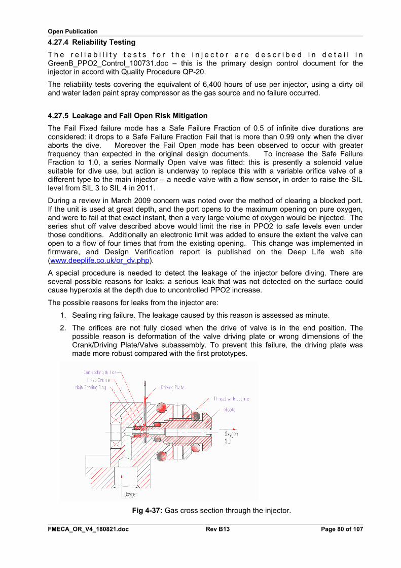
Open Publication
4.27.4 Reliability Testing
T h e r e l i a b i l i t y t e s t s f o r t h e i n j e c t o r a r e d e s c r i b e d i n d e t a i l i nGreenB_PPO2_Control_100731.doc – this is the primary design control document for theinjector in accord with Quality Procedure QP-20.
The reliability tests covering the equivalent of 6,400 hours of use per injector, using a dirty oiland water laden paint spray compressor as the gas source and no failure occurred.
4.27.5 Leakage and Fail Open Risk Mitigation
The Fail Fixed failure mode has a Safe Failure Fraction of 0.5 of infinite dive durations areconsidered: it drops to a Safe Failure Fraction Fail that is more than 0.99 only when the diveraborts the dive. Moreover the Fail Open mode has been observed to occur with greaterfrequency than expected in the original design documents. To increase the Safe FailureFraction to 1.0, a series Normally Open valve was fitted: this is presently a solenoid valuesuitable for dive use, but action is underway to replace this with a variable orifice valve of adifferent type to the main injector – a needle valve with a flow sensor, in order to raise the SILlevel from SIL 3 to SIL 4 in 2011.
During a review in March 2009 concern was noted over the method of clearing a blocked port.If the unit is used at great depth, and the port opens to the maximum opening on pure oxygen,and were to fail at that exact instant, then a very large volume of oxygen would be injected. Theseries shut off valve described above would limit the rise in PPO2 to safe levels even underthose conditions. Additionally an electronic limit was added to ensure the extent the valve canopen to a flow of four times that from the existing opening. This change was implemented infirmware, and Design Verification report is published on the Deep Life web site(www.deeplife.co.uk/or_dv.php).
A special procedure is needed to detect the leakage of the injector before diving. There areseveral possible reasons for leaks: a serious leak that was not detected on the surface couldcause hyperoxia at the depth due to uncontrolled PPO2 increase.
The possible reasons for leaks from the injector are:
1. Sealing ring failure. The leakage caused by this reason is assessed as minute.
2. The orifices are not fully closed when the drive of valve is in the end position. Thepossible reason is deformation of the valve driving plate or wrong dimensions of theCrank/Driving Plate/Valve subassembly. To prevent this failure, the driving plate wasmade more robust compared with the first prototypes.
Fig 4-37: Gas cross section through the injector.
FMECA_OR_V4_180821.doc Rev B13 Page 80 of 107

Open Publication
During testing a further failure mode was found, whereby wear would cause an increase in the hysteresis of the drive system, or the orifices in their holders. The result was that the current consumption would increase by orders of magnitude because the orifice would hunt for its correct position – overshooting each time. Instead of a few steps every ten seconds, the orifice would be driven continuously. The PPO2 control would wander by up to 0.1 atm during this time. This failure mode was eliminated by replacing the stepper motor and gearbox in the injector with a direct drive using a voice coil motor, and measuring the orifice position directly with a laser and CMOS imaging array sensor. The response time of the injector, from fully open to fully closed was also improved: from 3 seconds to 20ms so that if there is a major failure such that the controller has to drop back to a binary operating mode, with bang-bang control, it can do this effectively without demanding a lot of power. The injector requires no power to hold the orifice in a static position.
Further consideration of the failure modes of the injector determined that a means to prevent the PPO2 rising above safe limits was needed, in case the rebreather detects a serious fault on the surface and opens the injectors, then is passed through an interlock and used at great depth: the oxygen flow under those conditions would be hazardous. A normally open solenoid that was assessed and tested for diving applications was fitted upstream of the injector to shut off the gas supply should this occur. To prevent this solenoid creating an hypoxia risk, it is a normally open solenoid, tested to 36G acceleration forces, and when it closes, it operates in a mode that maintains the PPO2 to a set point 0.2 atm higher than the normal target set point using a proportional linear feedback system that is totally independent of the main injector.
4.27.6 Contamination Risk Mitigation
All user manuals contain specific instructions, emphasised by brightly coloured warningmarkers, that only clean gases are to be used with the rebreather. During an independent test,a fitting was machined and used to connect air to the bail out connectors. This fitting was notcleaned thoroughly after manufacture, resulting in machine oil being blown into the gas manifoldof the OR_Umbilical rebreather under test. Two rebreathers were affected. Both resulted in oilcontamination of the manifold, and this carbonised when oxygen was switched on: there was novisible external sign because all parts are highly oxygen compatible, but the injector sensordetected a marked reduction in signal strength when the oxygen was switched on, resulting in iteventually going into a dive abort failure mode where the orifice is open.
A software check for the contamination was subsequently added to eCCR rebreather models,using the reduction in light output as the sensing element. Filters were fitted to the injector itselfthat use a membrane that blocks liquids, including oils, and smoke particles that may interferewith the injector.
A further fault mode was observed during the same series of tests, where the oxygen runs outat depth, then the rebreather is brought to the surface. This results in water droplets beingsucked into the injector. To prevent this fault, a second filter was added after the injector, againusing both sintered and membrane filter elements.
FMECA_OR_V4_180821.doc Rev B13 Page 81 of 107
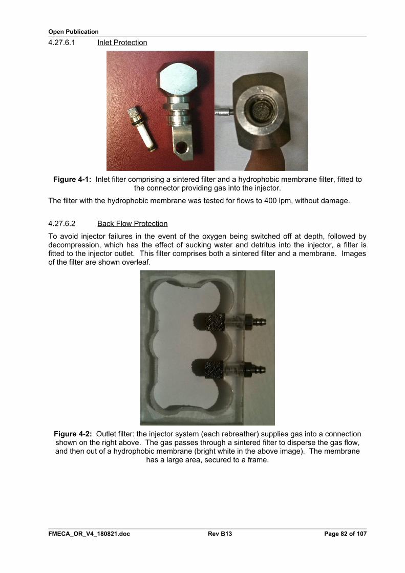
Open Publication
4.27.6.1 Inlet Protection
Figure 4-1: Inlet filter comprising a sintered filter and a hydrophobic membrane filter, fitted tothe connector providing gas into the injector.
The filter with the hydrophobic membrane was tested for flows to 400 lpm, without damage.
4.27.6.2 Back Flow Protection
To avoid injector failures in the event of the oxygen being switched off at depth, followed bydecompression, which has the effect of sucking water and detritus into the injector, a filter isfitted to the injector outlet. This filter comprises both a sintered filter and a membrane. Imagesof the filter are shown overleaf.
Figure 4-2: Outlet filter: the injector system (each rebreather) supplies gas into a connectionshown on the right above. The gas passes through a sintered filter to disperse the gas flow,and then out of a hydrophobic membrane (bright white in the above image). The membrane
has a large area, secured to a frame.
FMECA_OR_V4_180821.doc Rev B13 Page 82 of 107
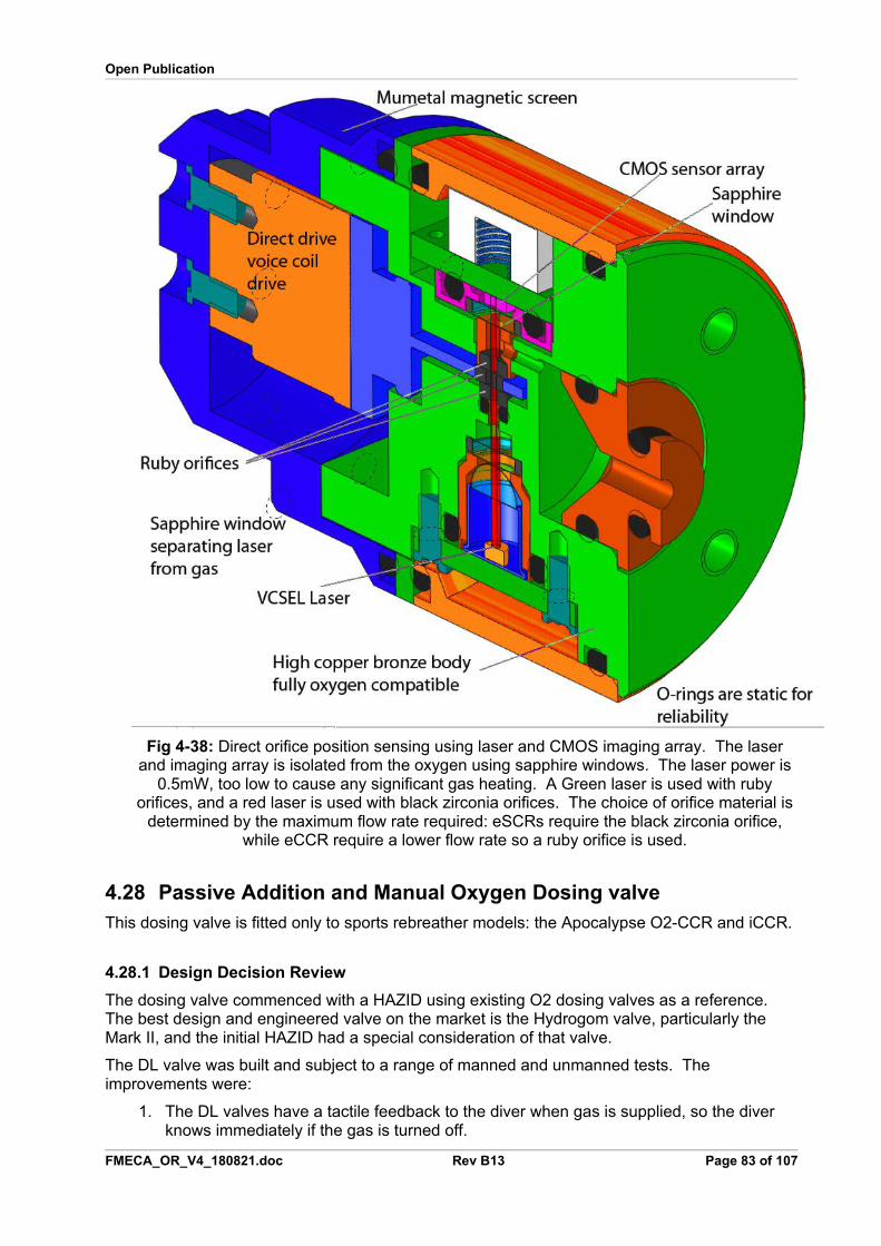
Open Publication
Fig 4-38: Direct orifice position sensing using laser and CMOS imaging array. The laserand imaging array is isolated from the oxygen using sapphire windows. The laser power is
0.5mW, too low to cause any significant gas heating. A Green laser is used with rubyorifices, and a red laser is used with black zirconia orifices. The choice of orifice material is
determined by the maximum flow rate required: eSCRs require the black zirconia orifice,while eCCR require a lower flow rate so a ruby orifice is used.
4.28 Passive Addition and Manual Oxygen Dosing valveThis dosing valve is fitted only to sports rebreather models: the Apocalypse O2-CCR and iCCR.
4.28.1 Design Decision Review
The dosing valve commenced with a HAZID using existing O2 dosing valves as a reference. The best design and engineered valve on the market is the Hydrogom valve, particularly the Mark II, and the initial HAZID had a special consideration of that valve.
The DL valve was built and subject to a range of manned and unmanned tests. The improvements were:
1. The DL valves have a tactile feedback to the diver when gas is supplied, so the diver knows immediately if the gas is turned off.
FMECA_OR_V4_180821.doc Rev B13 Page 83 of 107
Open Publication
2. The first version of the DL valve was fitted to the first stage regulator to ensure it is easyto find. However, very larger divers may have difficulty reaching this.
3. Manual flow rates from 4 litres per minute to 90 litres per minute were assessed by a series of test dives: the bleed flow rate was always 0.7 litres per minute. The 4 litre perminute figure was deliberately below the 12 litre per minute minimum established through formal modelling of ascents to allow metabolic rates to be monitored. These confirmed earlier findings from metabolic studies by DL, that a diver’s metabolic rate is around 1.4 litres per minute in gentle swimming, but typically 50% higher in the first few minutes of the dive. At this rate, the 4 litres per minute flow was a quarter of that needed for safe use, particularly on ascent.
4. The pressure on the valve button was adjusted: the first valve had a 3kg pressure, which gave cramp in cold water to some divers, especially with the 4 litre per minute manual flow rate. The pressure was reduced to 1kg.
5. The high flow rates that were tested are very controllable for experienced divers, but a novice may inject too much gas. There is no control of the amount of gas injected when the rate is 90 litres per minute, whereas a lower rate allows a diver to determine mentally how long they need to press the button for.
6. Where there are twin hoses, divers will swap these accidentally. A single concentric hose was adopted to prevent this, with a special thin bore to limit flow in the event of a hose failure.
7. A swivel was built into the valve.
8. The valve length was made long enough for a full hand grip, and positioned just above a diver’s crotch so that all divers can find it: obese divers posed a particular challenge. Over the shoulder mounting was a problem with many divers, particularly those with impaired vision.
9. The blockage risk on the O2 line was managed by the valve orifice expanding to the 16 lpm flow when the manual button is pressed: it is not a fixed orifice with a bypass as it ison all other valves that were examined. This process makes the orifice self cleaning. A15 micron filter prior to the valve prevents cylinder debris from blocking the orifice at these large orifice sizes, and the large size allows corrosion products from the filter to pass through the valve.
10. In one version of the valve, the tactile feedback was increased but it was found the valve button would stick on if uneven pressure was applied when grit was in the button. This was examined in detail, and resolved by design changes.
11. Sand and grit in the button barrel was a particular problem examined in detail. The Hydrogom valve has many grit vents, but in very extreme circumstances, such as whenthe valve drags along a silty bottom, it could still block through ingress through those same vents. The approach was taken to avoid grit vents, and keep tolerances tight to avoid grit getting into the valve. This problem is very difficult to resolve entirely, but the combination of tight tolerance and water pressure pushing out grit in the barrel each time the valve is pressed, appears to be the best solution.
4.28.2 Risk Assessment
The risks are addressed by a verification regime of the valve. These are:
1. Oxygen compatibility: the seat is sapphire and all parts in contact with O2 in the valveare bronze. The flow rate to the valve is limited to prevent adiabatic compression.
2. Overpressure of intermediate gas: a 16 bar intermediate pressure is used and the valvehas been tested with 300 bar gas (modifications were carried out to prototypes – the firstprototypes withstood only 140 bar).
FMECA_OR_V4_180821.doc Rev B13 Page 84 of 107
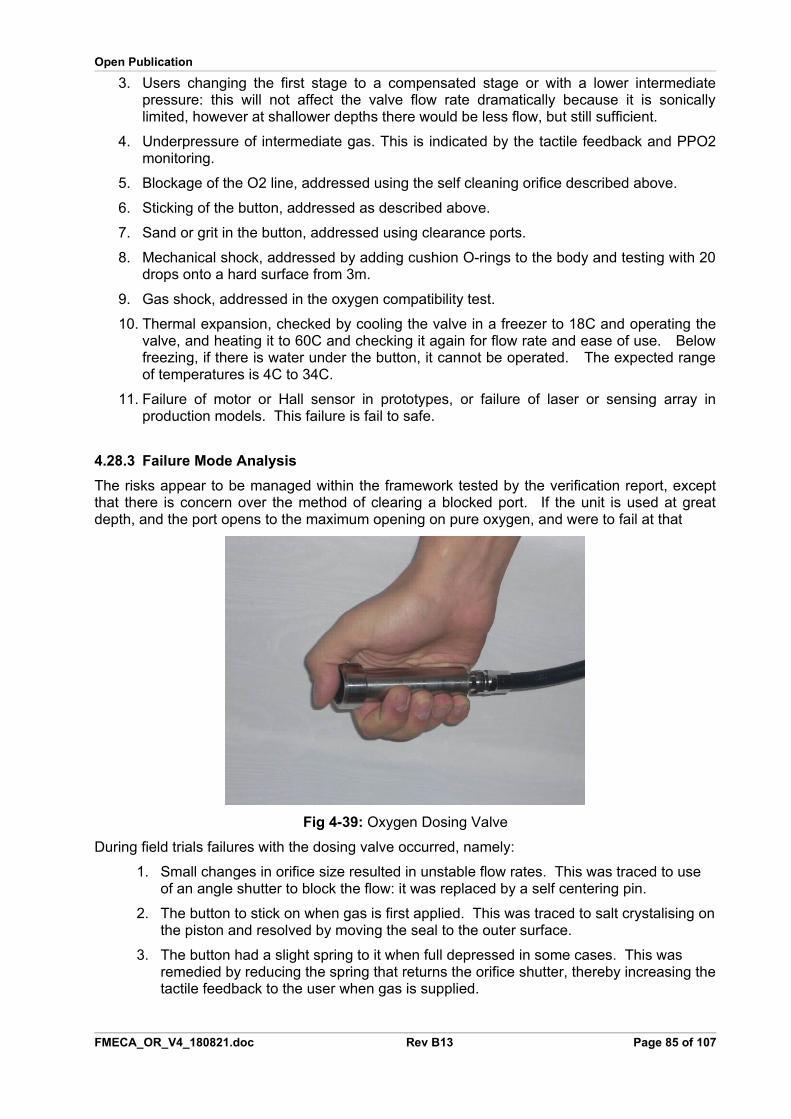
Open Publication
3. Users changing the first stage to a compensated stage or with a lower intermediatepressure: this will not affect the valve flow rate dramatically because it is sonicallylimited, however at shallower depths there would be less flow, but still sufficient.
4. Underpressure of intermediate gas. This is indicated by the tactile feedback and PPO2monitoring.
5. Blockage of the O2 line, addressed using the self cleaning orifice described above.
6. Sticking of the button, addressed as described above.
7. Sand or grit in the button, addressed using clearance ports.
8. Mechanical shock, addressed by adding cushion O-rings to the body and testing with 20drops onto a hard surface from 3m.
9. Gas shock, addressed in the oxygen compatibility test.
10. Thermal expansion, checked by cooling the valve in a freezer to 18C and operating thevalve, and heating it to 60C and checking it again for flow rate and ease of use. Belowfreezing, if there is water under the button, it cannot be operated. The expected rangeof temperatures is 4C to 34C.
11. Failure of motor or Hall sensor in prototypes, or failure of laser or sensing array inproduction models. This failure is fail to safe.
4.28.3 Failure Mode Analysis
The risks appear to be managed within the framework tested by the verification report, exceptthat there is concern over the method of clearing a blocked port. If the unit is used at greatdepth, and the port opens to the maximum opening on pure oxygen, and were to fail at that
Fig 4-39: Oxygen Dosing Valve
During field trials failures with the dosing valve occurred, namely:
1. Small changes in orifice size resulted in unstable flow rates. This was traced to use of an angle shutter to block the flow: it was replaced by a self centering pin.
2. The button to stick on when gas is first applied. This was traced to salt crystalising onthe piston and resolved by moving the seal to the outer surface.
3. The button had a slight spring to it when full depressed in some cases. This was remedied by reducing the spring that returns the orifice shutter, thereby increasing thetactile feedback to the user when gas is supplied.
FMECA_OR_V4_180821.doc Rev B13 Page 85 of 107
Open Publication
These issues are described in detail in a supplement to this FMECA (FMECA_Supplemental_O2_Dosing_080810.pdf). All causes for failure were addressed and resolved.
4.29 Battery Housings
4.29.1 Design Decision Review
The batteries in the rebreather controllers are housed outside the rebreather in stainless steelpressure vessels designed to withstand 1400msw and the vapourisation of the battery. Thevessels are small stainless steel tubes, clearly visible in Figs 3-1, 3-7 and 4-8.
The batteries used for rebreather controllers are from Valence, Saphion Safe Lithium range,including the IFR18650e and IFR18650p. These are a Lithium phosphate chemistry which areguaranteed not to explode or catch fire. These require a custom charger because they have anominal voltage of 3.7V charging at 4.2V, instead of the usual 3.2V nominal and 3.65Vcharging: this was designed and verified. A full characterisation of the cells was carried out andthe report published on the Deep Life web site: see HT www.deeplife.co.uk/or_dv.phpTH
The helium susceptibility of the Valence batteries was tested and found to pass withpressurisation to 1400msw in pure helium, soak for three weeks, and rapid depressurisation (inunder one second). Three cycles were carried out.
LiMn cells of 18650 size were submitted to SIRA for ATEX testing and met the requirements atT3, ensuring no safety hazard when damaged or overcharged.
A full pressure stress analysis has been carried out and was reviewed.
The penetrator from the battery pack to the electronics chamber has been tested andwithstands 1400msw of pure helium.
For monitor applications, the alternative approach was taken of using thin cells, of a LithiumMixed-oxide chemistry which rupture without explosion sufficient to breach the monitor housing.The compartment with the cells is separate from the breathing loop and gas tight.
4.29.2 Compliance
IMCA AOCD 35 requires battery packs to have built in current limiting. The battery housing isnot a replaceable battery pack so is not subject to this restriction, but for reasons of safety thecurrent is limited by suitable PCB traces on the PCB that forms the penetrator from the batterypack to the electronics chamber.
The LiMn batteries used in the Open Safety eCCRs and HUD were submitted to SIRA, Chesterfor test in 2017 to ATEX standards. The batteries passed at T3, meaning they pose no fire orthermal hazard when crushed, punctured or overcharged.
4.29.3 Risk Assessment
The following risks from the battery housing were identified:
1. Leaking. The seals could leak. This is unlikely, and does not have any catastrophiceffect on the equipment: the failure of the cell is detected.
2. Mechanical damage is unlikely given the small diameter of the tubes and the relativelythick walls, or the protected cell in the case of the rebreather monitors. A more likelyfailure is in the case of a heavy drop onto the battery compartment may break away from
FMECA_OR_V4_180821.doc Rev B13 Page 86 of 107
Open Publication
the rebreather. This would damage the rebreather electronics. The batterycompartments are protected from this risk by being mated closely with the rebreatherwalls, so stress is not focused on one point, and the rebreather cover should prevent thecompartments from suffering impact while in service.
3. Corrosion. The material chosen to protect the cells is a marine grade stainless steel,SS320, with good corrosion characteristics. It is extremely improbable that corrosionwould penetrate 1.5mm of this stainless steel between service intervals unless the unit isexposed to strong acids.
4. Cell thermal overrun. Only ATEX certified cells are used.
5. Snag points. On the twin scrubber package, the batteries from a local snag point formonofilament line. It is important that a cover is used over the rebreather to avoid thisrisk.
4.29.4 Failure Mode Analysis
The failure modes are of leaking or mechanical damage.
Leaks will cause early failure of the batteries in that compartment but no other detrimentaleffects. The compartment may warm up if the leak is a conductive liquid such as sea water.
The effect of mechanical damage is mitigated by reducing local stresses to the minimum.
4.30 Oxygen Cells and Cell Holders
4.30.1 Design Decision Review
Extensive risk and failure analysis was carried out on galvanic oxygen cells and is reported inDV_O2_cell_study_RevE_090722.pdf
A diverse method of measuring O2 was developed using sol-gels: this work is continuing as it isa requirement for the system to move from SIL 3 to SIL 4 certification. This sol-gel sensor hasnot had sufficient test for it to be considered an available technology under ALARP at this time,so galvanic cells only are used.
All user manuals included detailed information, instructions and warnings on the care and use ofoxygen cells that is in conformance with the findings in the O2 cell study.
All electronic modules using O2 cells have self test of the cells, using charge injection,capacitance and resistance methods, and have a software utility to enable the diver to checkthe cells before every dive.
The user manuals carry recommendations to test the cells every three months to at least aPPO2 of 2.35 atm,
The cells use SMB sockets exclusively, holding the cells off the circuit board in compliance withsafety requirements on the Deep Life Mantis system for tracking safety requirements.
The cells are held in cell holders designed to prevent water or vapour being trapped around thecells.
4.30.2 Risk Assessment
The failure modes of the cells are handled in the O2 Sensor Fusion algorithm other than thefollowing mechanically related failures:
1. Leaking. The cells may leak caustic liquids. This risk is mitigated by care instructionsand warnings in the user manuals.
FMECA_OR_V4_180821.doc Rev B13 Page 87 of 107
Open Publication
2. The cells may be physically damaged by puncture of the front membrane, by beingdropped, by exposure to freezing conditions, by exposure to temperatures in excess fo50C. These risks are mitigated by care instructions and warnings in the user manuals.
3. The cells may develop gas bubbles if decompressed quickly. This risks are mitigated bycare instructions and warnings in the user manuals. The cells have vent holes in thePCB behind the cell.
4. Cells are unreliable. At least three cells are fitted to each system, and checked beforeand during the dive automartically.
5. A water or vapour trap may develop around the front membrane. The cell holder isdesigned such that water or vapour cannot remain around the cell membrane: there isno well around the membrane.
6. Fitting of inappropriate or unapproved cells. The cells are tested automatically by theapparatus. No person has so far succeeded into tricking the system to use an incorrectcell.
4.30.3 Failure Mode Analysis
The failure modes are engineered to cause the cells to fail low. This is not possible in threecases:
where physical detachment of the anode occurs within the cell or
where the electrolyte has leaked or
where the load resistor has become open circuit or high impedance.
The last of these faults is detected automatically by the apparatus and the cell is screened out.,
An O2 Cell Fusion algorithm detects and screens out the other two remaining faults when usedin conjunction with automatic cell test, which involves injecting a charge periodically into the celland measuring the relaxation time.
4.31 Electronics Chamber
4.31.1 Design Decision Review
The electronics is in the rebreather head, separate from the breathing loop by a stainless steelplate secured with a circlip around its periphery, and two O-rings in series performing the seal.
The electronics chamber is filled with silicone oil. An expansion chamber is in the breathingloop, using a stainless steel tube and a piston. This means the electronics are at ambientpressure. This also means the walls of the chamber are not under stress, so helium should notmigrate through them into the oil: helium migration occurs when materials are under strain.
All components have been tested for helium susceptibility by exposing them to pure helium at1400msw for a minimum of 21 days. Components that fail this test have been eliminated fromthe design except for the pressure sensor, considered separately.
The isolation of the electronics from the breathing loop prevents any component from off-gassing into the breathing loop.
The electronics is connected to sensors via a DIN 41612 connector. These are known to behighly reliable, with a hard gold plated bifuricated contact onto a hard gold plated brass pin.The contacts are kept away from moisture by mounting them in the CO2 sampling area: watermolecules comprise 9 atoms compared to 3 atoms for CO2, allowing water to be kept out whileCO2 passes through the membrane to the sensors. The sensor area is also slightly warmer
FMECA_OR_V4_180821.doc Rev B13 Page 88 of 107
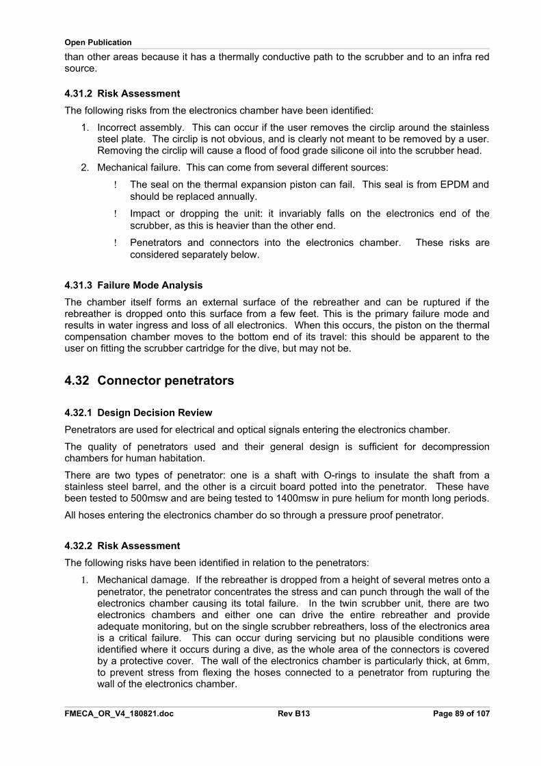
Open Publication
than other areas because it has a thermally conductive path to the scrubber and to an infra redsource.
4.31.2 Risk Assessment
The following risks from the electronics chamber have been identified:
1. Incorrect assembly. This can occur if the user removes the circlip around the stainlesssteel plate. The circlip is not obvious, and is clearly not meant to be removed by a user.Removing the circlip will cause a flood of food grade silicone oil into the scrubber head.
2. Mechanical failure. This can come from several different sources:
The seal on the thermal expansion piston can fail. This seal is from EPDM andshould be replaced annually.
Impact or dropping the unit: it invariably falls on the electronics end of thescrubber, as this is heavier than the other end.
Penetrators and connectors into the electronics chamber. These risks areconsidered separately below.
4.31.3 Failure Mode Analysis
The chamber itself forms an external surface of the rebreather and can be ruptured if therebreather is dropped onto this surface from a few feet. This is the primary failure mode andresults in water ingress and loss of all electronics. When this occurs, the piston on the thermalcompensation chamber moves to the bottom end of its travel: this should be apparent to theuser on fitting the scrubber cartridge for the dive, but may not be.
4.32 Connector penetrators
4.32.1 Design Decision Review
Penetrators are used for electrical and optical signals entering the electronics chamber.
The quality of penetrators used and their general design is sufficient for decompressionchambers for human habitation.
There are two types of penetrator: one is a shaft with O-rings to insulate the shaft from astainless steel barrel, and the other is a circuit board potted into the penetrator. These havebeen tested to 500msw and are being tested to 1400msw in pure helium for month long periods.
All hoses entering the electronics chamber do so through a pressure proof penetrator.
4.32.2 Risk Assessment
The following risks have been identified in relation to the penetrators:
1. Mechanical damage. If the rebreather is dropped from a height of several metres onto apenetrator, the penetrator concentrates the stress and can punch through the wall of theelectronics chamber causing its total failure. In the twin scrubber unit, there are twoelectronics chambers and either one can drive the entire rebreather and provideadequate monitoring, but on the single scrubber rebreathers, loss of the electronics areais a critical failure. This can occur during servicing but no plausible conditions wereidentified where it occurs during a dive, as the whole area of the connectors is coveredby a protective cover. The wall of the electronics chamber is particularly thick, at 6mm,to prevent stress from flexing the hoses connected to a penetrator from rupturing thewall of the electronics chamber.
FMECA_OR_V4_180821.doc Rev B13 Page 89 of 107
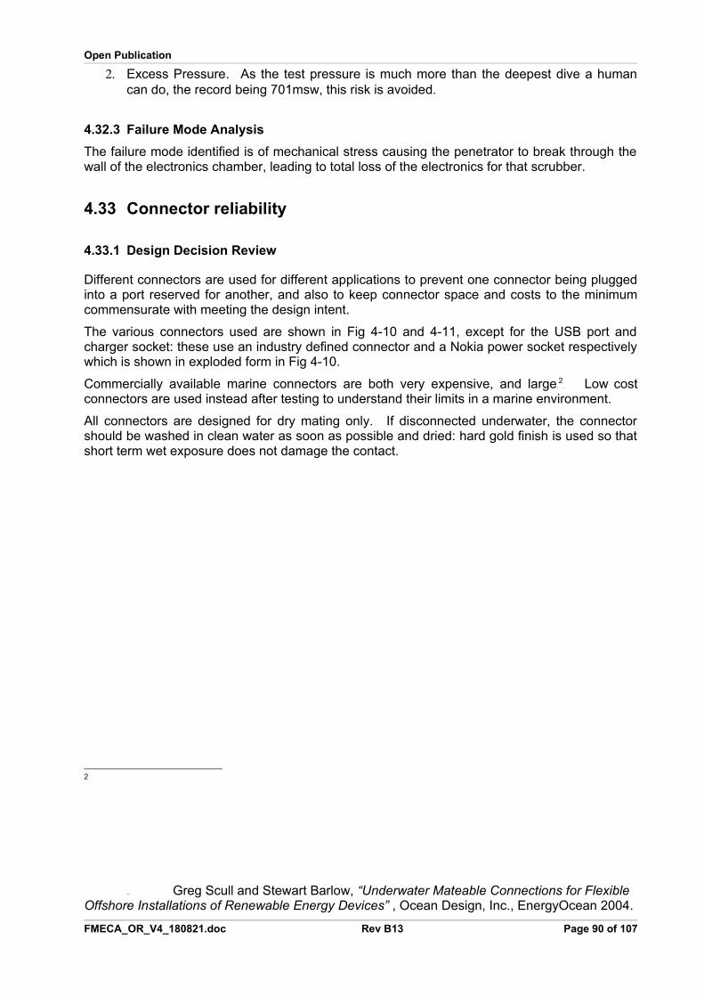
Open Publication
2. Excess Pressure. As the test pressure is much more than the deepest dive a humancan do, the record being 701msw, this risk is avoided.
4.32.3 Failure Mode Analysis
The failure mode identified is of mechanical stress causing the penetrator to break through thewall of the electronics chamber, leading to total loss of the electronics for that scrubber.
4.33 Connector reliability
4.33.1 Design Decision Review
Different connectors are used for different applications to prevent one connector being pluggedinto a port reserved for another, and also to keep connector space and costs to the minimumcommensurate with meeting the design intent.
The various connectors used are shown in Fig 4-10 and 4-11, except for the USB port andcharger socket: these use an industry defined connector and a Nokia power socket respectivelywhich is shown in exploded form in Fig 4-10.
Commercially available marine connectors are both very expensive, and large PF
2FP Low cost
connectors are used instead after testing to understand their limits in a marine environment.
All connectors are designed for dry mating only. If disconnected underwater, the connectorshould be washed in clean water as soon as possible and dried: hard gold finish is used so thatshort term wet exposure does not damage the contact.
2
TP
�PT Greg Scull and Stewart Barlow, “Underwater Mateable Connections for Flexible
Offshore Installations of Renewable Energy Devices” , Ocean Design, Inc., EnergyOcean 2004.
FMECA_OR_V4_180821.doc Rev B13 Page 90 of 107
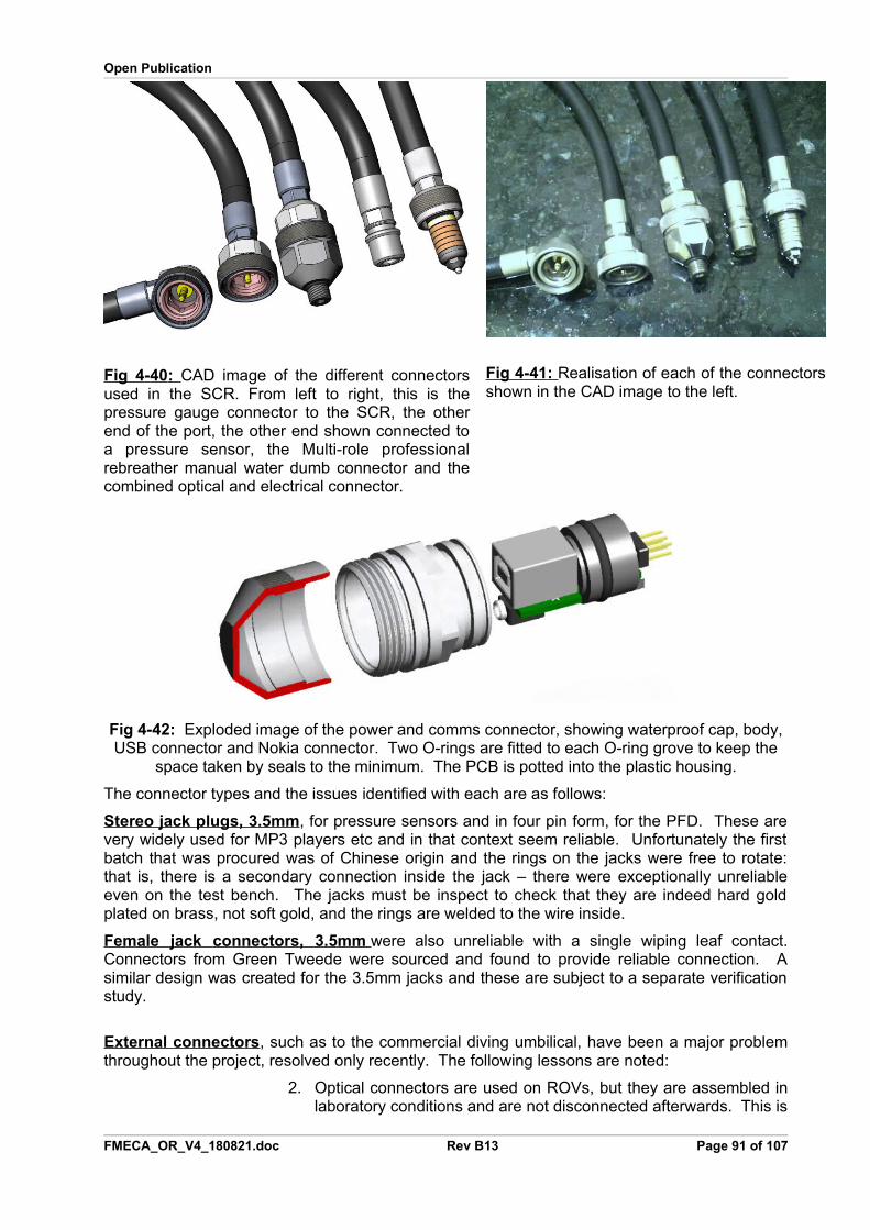
Open Publication
Fig 4 - 40 : CAD image of the different connectorsused in the SCR. From left to right, this is thepressure gauge connector to the SCR, the otherend of the port, the other end shown connected toa pressure sensor, the Multi-role professionalrebreather manual water dumb connector and thecombined optical and electrical connector.
Fig 4 - 41 : Realisation of each of the connectorsshown in the CAD image to the left.
Fig 4-42: Exploded image of the power and comms connector, showing waterproof cap, body,USB connector and Nokia connector. Two O-rings are fitted to each O-ring grove to keep the
space taken by seals to the minimum. The PCB is potted into the plastic housing.
The connector types and the issues identified with each are as follows:
Stereo jack plugs, 3.5mm, for pressure sensors and in four pin form, for the PFD. These arevery widely used for MP3 players etc and in that context seem reliable. Unfortunately the firstbatch that was procured was of Chinese origin and the rings on the jacks were free to rotate:that is, there is a secondary connection inside the jack – there were exceptionally unreliableeven on the test bench. The jacks must be inspect to check that they are indeed hard goldplated on brass, not soft gold, and the rings are welded to the wire inside.
Female jack connectors, 3.5mm were also unreliable with a single wiping leaf contact.Connectors from Green Tweede were sourced and found to provide reliable connection. Asimilar design was created for the 3.5mm jacks and these are subject to a separate verificationstudy.
External connectors, such as to the commercial diving umbilical, have been a major problemthroughout the project, resolved only recently. The following lessons are noted:
2. Optical connectors are used on ROVs, but they are assembled inlaboratory conditions and are not disconnected afterwards. This is
FMECA_OR_V4_180821.doc Rev B13 Page 91 of 107
Open Publication
completely different to a connector on a rebreather, which ismated and disconnected several times a day in dirty conditions.Optical connectors caused very many failures during trials, andwere removed from the project, being replaced by electricalconnectors.
3. Dry connect, IP68 connectors, such as Lemo, Fischer, andsuchlike connectors, are not suitable for rebreathers. Wateringress causes shorts between signal and power lines, and just adrop of water on the connector when it is disconnected causes thewhole connector to gradually become unreliable.
4. All small connectors are fragile.
To resolve these issues, only full wet mateable connectors are used for external lines. Theseare Birns connectors, compatible with Seacons and others of the same type.
USB connector: an industry standard connector is used to charge all battery poweredequipment, other than the commercial diving rebreather. This connector is robust in service solong as the environment is dry.
Handset power and data connector. Handset and monitor connectors were found to befragile in service: divers would catch the handset in benching and then stand up, or stand on theconnector bending it. After trials, all data connectors were removed from the project and UHFRF was used instead. There is a 100dB loss in water after just one metre, so this approachworks even for non-mag systems. The O2 monitor, CO2 monitor and PFD communicate by RFwith a very high received signal power due to the air space between them, and the divecomputer communicates with a low received power (+7dBm transmitted power, -110dBmsensitivity on the receiver).
Sensors to Main Electronics. On the eCCR heads, a sensor board is connected using a DIN41612 connector with hard gold finish on nickel over phosphor bronze (female) and brass(male). The connector is protected from moisture and critical paths use multiple connector pinsin parallel. The only failures that have occurred have been when the pins have beencontaminated by epoxy during assembly.
4.33.2 Risk Assessment
The risks identified that are related to the connectors are:
1. Mechanical damage. If the scrubber assembly is dropped the unit tends to land on oneof the connectors. The worst case is where the connector is capped: when the hose isconnected, the hose acts as a shock absorber. If dropped from sufficient height, theconnector can punch through the scrubber housing causing complete failure. Thisfailure must be avoided by use of the rebreather cover, but may occur when a newscrubber cartridge is being fitted.
Action: It may be possible to further mitigate this risk by moulding a soft elastomer coverinstead of the stainless steel covers. This possibility should be investigated.
2. Contamination. The connectors can be contaminated with oil. In this case, there is aloss of electrical function from the connector. The effect of this is considered in theelectrical MTBCF and electrical FMECA reviews. Contamination of the optical connectorwith opaque material will cause loss of the optical connection.
3. Off-gassing. The connectors are not in the breathing loop, except for the DIN 41612connector. Action: The manufacturer should supply complete plastics disclosure. Someof these connectors use PVC, but most use a glass loaded nylon. It is important thatonly glass filled nylon is used.
FMECA_OR_V4_180821.doc Rev B13 Page 92 of 107
Open Publication
4. Leakage through the connector can occur if the O-rings are missing or damaged. Therate of the leak will be very low, but gradually the silicone oil thermal expansion pistonwill move to the bottom of its stroke and the user must be alert to this. If the user is notalert, there is a risk of electronics failure from water ingress.
5. Leakage of water onto the connector face can occur if O-rings are missing or damaged.This will short out electrical traces but should have no other deleterious effect short term.Long term, it would cause electrolysis of the contacts.
6. Incorrect assembly. This can have the same effect as leakage, due to omission of theO-ring. The connectors and penetrators are not user serviceable items and are notaccessible for removal or adjustment by the user.
7. Water on the face of the connector: the prevalence of this caused a change to wetmateable connectors only for all external connectors.
4.33.3 Failure Mode Analysis
Failures include loss of electrical and optical connections. This is detected by the electronicsand warnings flagged on either the Top Side Unit (commercial dive system) or on the handset.
Failures include water ingress with destruction of the electronics. This is a gradual failure andshould be observed by the user as the thermal expansion piston moving to one end of itsstroke.
4.34 Gas Port Mechanical Reliability
4.34.1 Design Decision Review
The gas port is as small as the design team could make it, while connecting to a regular hose.
Oxygen hoses should be in solid stainless steel, but the connector allows for flexible hose forMulti-role professional diving applications.
The port includes a 15 micron sintered bronze filter.
4.34.2 Risk Assessment
The following risks have been identified in relation to the gas connector:
1. Mechanical damage. The gas port projects from the side of the unit and if the scrubber isallowed to drop onto a hard surface from 3m or more, the gas port can cut through thescrubber housing. The result will generally fail pre-dive positive and negative pressurechecks, but it is plausible that it may pass depending on how the damage occurs, andfail during a dive. Such a failure would lead to flooding of the scrubber housing, whichwould be detected by the electronics due to the increased pressure across the scrubber,and signal bail out.
2. Incorrect Assembly. The port is not a user serviceable item. However, it is possible forthe user to remove the 15 micron filter. This would increase considerably the risk of theorifices being blocked by debris from the gas cylinder or line. No satisfactory solutionhas been found to this, other than labeling the port using silk screening.
3. Omission of filter. This is considered under “Incorrect assembly” above.
4. Clogging of filter. If the gas cylinders have been allowed to empty underwater, duringascent they will suck in water causing very rapid corrosion. The sintered bronze filter willturn a green colour with corrosion and clog.
FMECA_OR_V4_180821.doc Rev B13 Page 93 of 107
Open Publication
5. Breakup of filter. If the filter is very severely corroded, it can break up, leading toclogging of the orifices.
6. Contamination. If contaminants are allowed to enter the port, there is a risk of oxygenignition, or of blockage, or of contaminants entering the breathing gas. This situationshould not occur in a dive system, but it is plausible that it can occur if for example, anuntrained person uses a general grease or silicone grease on the port. Thehydrocarbon sensor in the unit will likely pick up use of incompatible greases.
4.34.3 Failure Mode Analysis
The failure modes that can occur are:
Blocking of orifice ports.
Contamination of the breathing gas with substances harmful to health.
Mechanical damage resulting in water ingress into the breathing loop.
None of these failures should occur in service: all are detected by the electronics during pre-dive checks, though detecting contamination depends on what the contaminant is.
Each of these failure modes are handled by the electronics should they occur.
4.35 Scrubber Stick
4.35.1 Design Decision Review
The scrubber stick can be seen clearly in Fig 3-2, 3-2 and Fig 3-7 as the rod in the centre of thescrubber cap. The rod measures the temperature of the scrubber in twelve locations andmeasures the pressure across the scrubber. The structure at the base of the stick holds thegas contamination monitors (CO2, CO and HC).
The scrubber stick is the result of several iterations, from design, build, test and improvement.Earlier scrubber sticks were much thinner than the present design, but were damaged easily. Adecision was taken to re-engineer the stick such that it could not be damaged under anyplausible circumstances other than falling from a height of several metres directly onto the stick,in which the stick base breaks. Since that re-engineering, no stick failures have occurred evenwith deliberate attempts to damage the stick.
The stick material is wound carbon fibre: this gives adequate thermal insulating propertiescombined with very high strength. Metals conduct heat too well down the stick for the stick tooperate correctly. Plastic materials did not provide the strength required without much thickerwalls.
4.35.2 Risk Assessment
The risks identified that relate to the mechanical functions of the scrubber stick are:
11. UV exposure. If the scrubber is left open on deck of a dive vessel or exposed nearwhere arch welding is carried out, the scrubber stick can receive a large UV exposure.Carbon has excellent resistance to UV: it is added to other plastics to provide UVresistance.
12. Chemical contamination. The carbon fibre tube has good resistance to oils, acids andstrong caustic solutions, but solutions can penetrate to the circuit board through thesensing holes. To mitigate this risk, the holes must be filled with a hard setting resinduring manufacturing.
FMECA_OR_V4_180821.doc Rev B13 Page 94 of 107
Open Publication
13. Mechanical Damage. None in a test group were able to damage the 22mm O.D. carbontube used for the scrubber stick, after drilling.
14. Wear. Each time the scrubber cartridge is removed, the scrubber core slides over thescrubber stick. This will lead to a small amount of wear. The stick is very strong andwears much more slowly than the EAC cores. The life is more than 10,000 EACexchanges.
4.35.3 Failure Mode Analysis
The failure mode of the scrubber stick is fracturing or breakage of the base when the openscrubber cap is dropped onto the scrubber stick end, onto a hard surface. This failure can alsooccur if the scrubber stick is crushed, such as under the wheels of a vehicle. It is unreasonableto protect the stick from such levels of abuse. The consequential electronics failure is detectedby the electronics, and the equipment must be returned to factory for repair: in reality, if suchdamage is observed, the entire scrubber cap and cap electronics should be replaced.
4.36 CO2 sensor and window
4.36.1 Design Decision Review
The CO2 sensor has four windows. Pressure on the windows causes a change in sensorcharacteristics, then with increasing pressure, permanent failure of the sensor.
The sensor is protected from this by a sapphire window, 14mm in diameter. Full stress and deformation analysis has been carried out on the window, the results being reported in the document CO2_Window Stress_051230.pdf.
FMECA_OR_V4_180821.doc Rev B13 Page 95 of 107
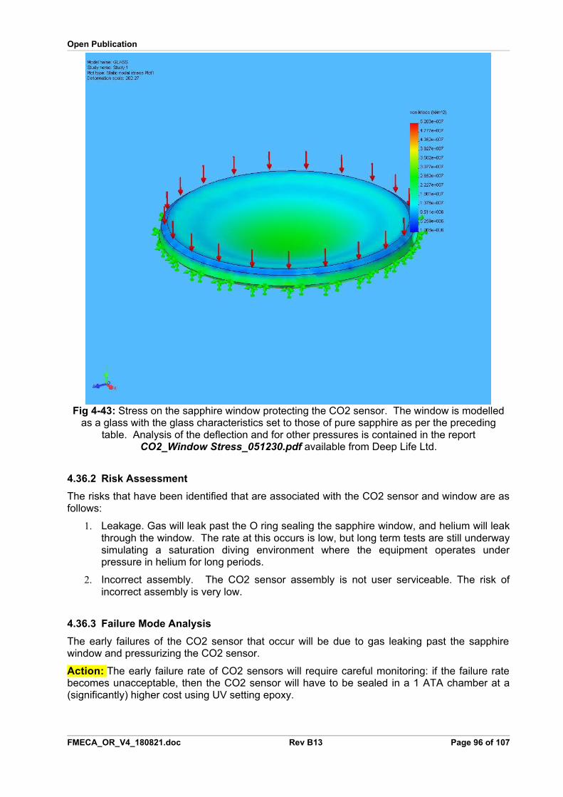
Open Publication
Fig 4-43: Stress on the sapphire window protecting the CO2 sensor. The window is modelledas a glass with the glass characteristics set to those of pure sapphire as per the preceding
table. Analysis of the deflection and for other pressures is contained in the reportCO2_Window Stress_051230.pdf available from Deep Life Ltd.
4.36.2 Risk Assessment
The risks that have been identified that are associated with the CO2 sensor and window are asfollows:
1. Leakage. Gas will leak past the O ring sealing the sapphire window, and helium will leakthrough the window. The rate at this occurs is low, but long term tests are still underwaysimulating a saturation diving environment where the equipment operates underpressure in helium for long periods.
2. Incorrect assembly. The CO2 sensor assembly is not user serviceable. The risk ofincorrect assembly is very low.
4.36.3 Failure Mode Analysis
The early failures of the CO2 sensor that occur will be due to gas leaking past the sapphirewindow and pressurizing the CO2 sensor.
Action: The early failure rate of CO2 sensors will require careful monitoring: if the failure ratebecomes unacceptable, then the CO2 sensor will have to be sealed in a 1 ATA chamber at a(significantly) higher cost using UV setting epoxy.
FMECA_OR_V4_180821.doc Rev B13 Page 96 of 107

Open Publication
4.37 Sensor Bell Membrane
4.37.1 Design Decision Review
The purpose of the membrane is to prevent water vapour from invading the sensor bellcontaining the CO2, CO, HC, He and temperature sensors.
The membrane must pass CO2 and Hydrocarbons but stop water vapour. The chemicalcomposition of the water vapour molecule is H6O3, so is a large molecule compared to CO2,CO or He.
The molecular size of hydrocarbons depends on which hydrocarbon is involved. This issue ofresolving hydrocarbons is particularly acute because some have only mild anesthetic effectssimilar to argon, while others are highly toxic and carcinogenic. In the environment where HCcontamination is likely to occur, the hydrocarbons occur in mixture, so detecting onehydrocarbon is deemed sufficient to detect that some hydrocarbon contamination has occurred.On this basis, propane is used as the calibration gas for hydrocarbons.
The approach to detecting CO2, CO and HC is the same: these gases all absorb infra red gas,albeit at different frequencies. A wide band infra red source is used, in combination with adetector with four filter windows to pick out the absorption frequencies for CO2, CO and HCalong with a reference window to compensate for fluctuations in the IR output of the IR emitter.
The membrane material is Zitex A105. This is the same material as used for oxygen sensorhydrophobic membranes. Alternative membranes from GE have been tested.
4.37.2 Risk Assessment
The risks associated with the hydrophobic membrane have been assessed as follows:
1. Chemical contamination. The membrane can be blocked by chemical contamination, oreven dust: it is a microfilter in surface mode. To mitigate this risk, the filter material isbrilliant white in colour so contamination can be seen from the change in membranecolour. The membrane should last the seven year service life of the equipment beforemajor overhaul is required, including replacement of the membrane.
2. Off-gassing. Many membranes use PTFE, which is considered a hazardous material touse within a breathing loop due to its high toxicity to avian life and at high temperature,to human tissues. To avoid this risk, a non PTFE membrane is used: this is fabricatedfrom a nylon material.
3. Puncturing. The membrane is a very thin material, with similar handling properties asdrafting polymer paper. Puncturing the membrane can occur if the user drops a sharpinstrument onto the membrane when changing a scrubber. Such a puncture should beapparent to the user, and the membrane replaced. Inspection of the membrane isincluded in the annual service.
4. Incorrect assembly. The membrane is not a user serviceable item, but incorrectassembly could occur if the wrong thickness of membrane material is supplied. To avoidthis risk, an incoming inspection of membrane material should be applied inmanufacturing, by measuring the membrane thickness and comparing with a samplewith which the sensor response time has been measured.
4.37.3 Failure Mode Analysis
Dust or chemical contamination is the only plausible failure mode that should occur, if guidelinesare followed.
FMECA_OR_V4_180821.doc Rev B13 Page 97 of 107
Open Publication
The effect of dust or chemical contamination is an increase in the response time of the CO2,CO, HC and Helium sensors. Such contamination can be detected by the user by the change incolour of the membrane.
A further failure mode exists where the membrane is punctured by a sharp instrument droppedby the user when changing the scrubber cartridge. This should be apparent to the user.
If the user refits the membrane using the wrong material, it may not pass CO2 or other gases,and complacency where the diver waits for CO2 to rise before finishing a dive, could have lethalconsequences. This should be addressed by training.
4.38 Scrubber Cartridge
4.38.1 Design Decision Review
As reported for the FMECA assessment of the scrubber housing in Section X4.22X, tests werecarried out on granular scrubber materials: none of these would meet the requirements ofEN61508 at SIL 3 level, because of multiple faults, including a four fold rise in breathingresistance when wet, risk of caustic cocktail to the diver, dust hazards, tunnelling hazards inparticular orientations in any of the axial designs that were considered, and inability to controlsufficiently the user’s placement of the scrims. The design therefore adopts the MicroporeExtendAir Cartridges (EACs) which do not carry any of these problems, other than as set outbelow.
The design team tested the EACs and found them to perform well, but the seal took 10% of thescrubber volume and was prone to leak if the EAC was damaged. The seal design wasreplaced.
The design team found the original EACs were very difficult to monitor due to a thick small borecentral winding tube. EAC monitoring through that tube was also prone to damage of thesensors. These problems were addressed by Micropore by increasing the bore size andreducing the core support thickness.
4.38.2 Risk Assessment
Detailed information on the EACs performance in various system fault conditions was providedby Micropore Inc, and this data was verified by Deep Life Ltd. This data confirms the EAC canwithstand flooding for up to 30 minutes, and up to 5 minutes while remaining operational afterclearing the flood, and that the solution has a pH that does not form a hazard to health. MSDShave been provided which indicate no off-gassing from the plastic used.
The risks remaining with the Micropore EACs are:
1. Replacement with an expired cartridge. To mitigate this risk, the scrubber canister isdesigned such that the user must visibly damage the scrubber cartridge to remove itafter use. During use, the EAC swells and binds to the scrubber stick and the cartridgewall. The method to remove the spent cartridge in the instruction manual is to use twocorkscrews, supplied with the equipment, to screw into the open face of the cartridgeand pull it out. This leaves obvious damage to the scrubber, so the user should notreplace a spent cartridge with the same. As a further monitoring measure, CO2 levelsare monitored electronically, as is the scrubber thermal characteristics as a function ofgas flow and gas density, to signal a scrubber is outside specification.
2. Mechanical Damage in transit. This generally damages the end of the cartridge. Thefailure should be detected by the CO2 monitor and the scrubber health monitor.
3. Flooding. After being flooded for more than 30 minutes, the pH rises to a level thatstarts to present a caustic cocktail to the diver. Such a flood is detected by theelectronic monitoring due to the rise in pressure across the scrubber.
FMECA_OR_V4_180821.doc Rev B13 Page 98 of 107
Open Publication
4.38.3 Failure Mode Analysis
The failure mode of the EAC is CO2 breakthrough.
The failure is managed within the system by monitoring CO2 levels using a CO2 sensor, bymonitoring scrubber characteristics and comparing them with a template compensated for gasdensity and flow, and by user training.
4.39 Breathing Gas HeatingAdjustable breathing gas heating is likely to become a requirement in NORSOK U-100. Hitherto, the exothermic reaction from the scrubber g and the high humidity was put forward as compliance with NORSOK U-100. Rev. 1 Aug 1999 7.7.1 which states
“The temperature control for divers in the water and the atmosphere of chambers, bells andhabitats shall be sufficiently accurate to ensure thermal balance and comfort for the divers/occupants at all times.” and “Active breathing gas heaters are to be used when diving deeperthan 150msw”
U-100 Rev. 2 (unpublished as of Feb 2007) has added the sentence “The gas temperature shallbe adjustable”.
Norsok U-101§5.9 gives actual maximum temperatures for the breathing gas. Giving an upperlimit for both dry and fully humidified breathing gas. It is then open to interpretation as to if thenarrow temperature band below 150m applies to dry breathing gas only in Norsok U-101 Rev.1§6.3.10. This project has proceeded so far on the basis that it is just dry breathing gas, but nowthere is a requirement for adjustable heating, this position becomes more tenuous.
The automatic adjustment to different metabolic rates from the scrubber reaction is the oppositeof what is required: the amount of heating per breath is the same because the exothermicreaction in the scrubber reacts with the same amount of CO2 per breath, so when the breathingrate increases, so does the exothermic reaction. Unfortunately when the metabolic rateincreases, the diver’s own exothermic processes are also generating more heat.
In view of the pending change to U-100, the project has included a safe gas heating elementwas developed that could be used to address this requirement in the standard for extremelydeep diving. The electronics meets SIL 3 requirements when implemented on inhale andexhale breathing gas.
The cross section of the breathing gas heater maintains equivalency with a 36mm tube, sothere is no impact on breathing resistance or WOB: this is achieved using a 42mm I.D. tube witha flat heating element of 50 sq.cm.
4.39.1 Design Decision Review
The design uses heating elements in the counterlungs to heat the diver’s gas to meet theNORSOK safety requirements and to maximise scrubber life.
The results of trials on how breathing gas heating can be achieved in a rebreather aredescribed in the document DV_Breathing_gas_thermal_ctrl_061228b.pdf
The heater used a carbon self limiting material produced by EXO2. A Safety Analysis of theEXO2 heating material is contained in document SafetyRep_Carbon_heaters_061225.pdf Aredesign using a nichrome heater in the hose immediately before the mouthpiece was adoptedin its place.
4.39.2 Risk Assessment
A very detailed analysis of the diver’s thermal balance was considered. This was based on adraft report from Thelma, as part of this project, of the diver’s thermal balance in -4C water and4C sea water.
FMECA_OR_V4_180821.doc Rev B13 Page 99 of 107
Open Publication
In manned trials in over 400msw, the diver could not get back to the bell and up the bell ladder,which was only 2m away, when gas and suit heating was switched off. At these depths the heatjust pours out of the diver’s lungs due to the density of the gas. The water temperature involvedwas much warmer than the extreme cold conditions considered by Thelma.
4.39.3 Failure Mode Analysis
The meeting fully accepted that at extreme depths gas heating becomes a critical safetyelement.
Careful consideration needs to be given to what point this moves from a SIL 0 upwards as thereis no requirement for active gas heating shallower than 150 m (Norsok U-100) The very natureof the rebreather breathing loop makes the active heating less of a critical issue that forcurrently used equipment (at moderate depths and it could be argued for extreme depths). Thisissue should not be allowed to impact on the current testing as the system is fitted for activeheating (which will need to be demonstrated as part of the Norsok verification beyond 150m).
The question is raised, of whether it really becomes a SIL 3/4 system or will the rebreather loop avoid this thermal shocking of the divers respiratory system at extreme depths?
Formal safety reviews recognised the problems with suit heating identified in SafetyRep_Carbon_heaters_061225.pdf and noted that moving to carbon based self limiting materials did not affect the safety. The review meetings minuted reports that 3 P
rdP degree burns
had occurred to divers using the previous generation of suit heaters, and nothing seems to havechanged just by moving to the EXO2 heaters – the causes are still present. Alex Deas described a meeting with Robin Caird, Technical Director of EXO2 and inventor of their material, where both parties agreed the cause of the problems and actions to remedy these. DLhad put a design engineer onto the proposed solution, which was described in detail to the meeting. EXO2 were very helpful and are supporting fully these safety improvements. The meeting agreed this route forward, for all heaters (suit and gas heating), seemed to be sound, and awaited further information as the activity progressed. The issue of heating is now a criticalpath activity for the overall project. Trelleborg and other interested parties would be kept informed of progress: the suit heater and the gas heater should be identical to avoid unnecessary development.
A complete suit heater and a gas heater was designed. Tests carried out, and formal modelling by Thelma, show the heater function is SIL 0 (i.e. not a safety function) when a dry suit is used with a rebreather.
4.40 Gas Circuit in Umbilical Supplied Configuration
4.40.1 Design Decision Review
There are two gas circuits: one for Multi-role professional use and one for surface supplied(umbilical) diving where there is a multiplexer and power unit (Umbilical Terminator) on top ofthe rebreather.
The gas routing for the Multi-role professional diver is simple.
The gas routing for the umbilical supplied diver is more complex, and shown in the two figuresbelow.
FMECA_OR_V4_180821.doc Rev B13 Page 100 of 107
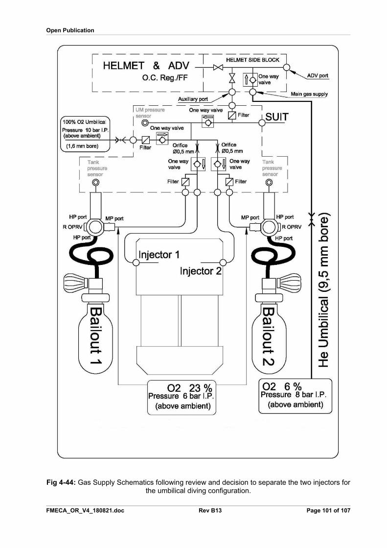
Open Publication
Fig 4-44: Gas Supply Schematics following review and decision to separate the two injectors forthe umbilical diving configuration.
FMECA_OR_V4_180821.doc Rev B13 Page 101 of 107
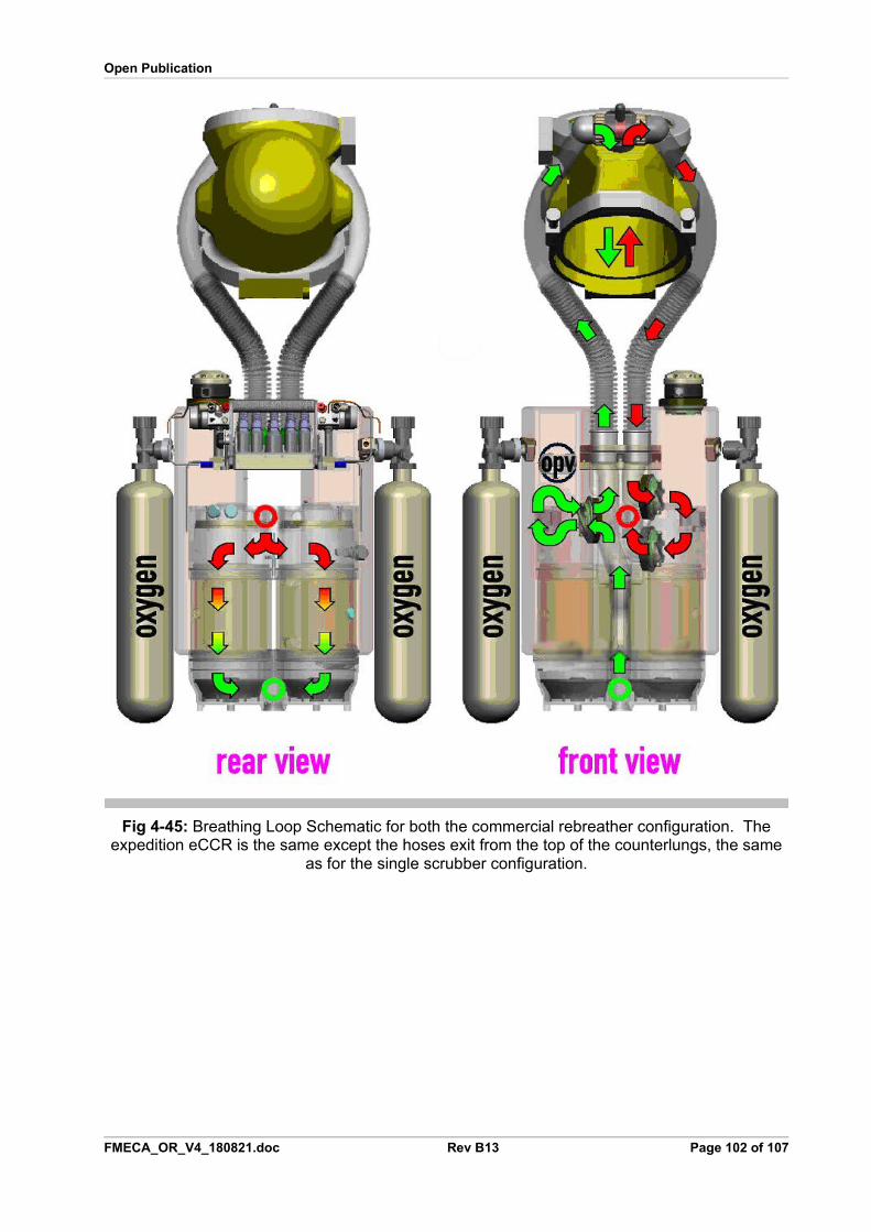
Open Publication
Fig 4-45: Breathing Loop Schematic for both the commercial rebreather configuration. Theexpedition eCCR is the same except the hoses exit from the top of the counterlungs, the same
as for the single scrubber configuration.
FMECA_OR_V4_180821.doc Rev B13 Page 102 of 107
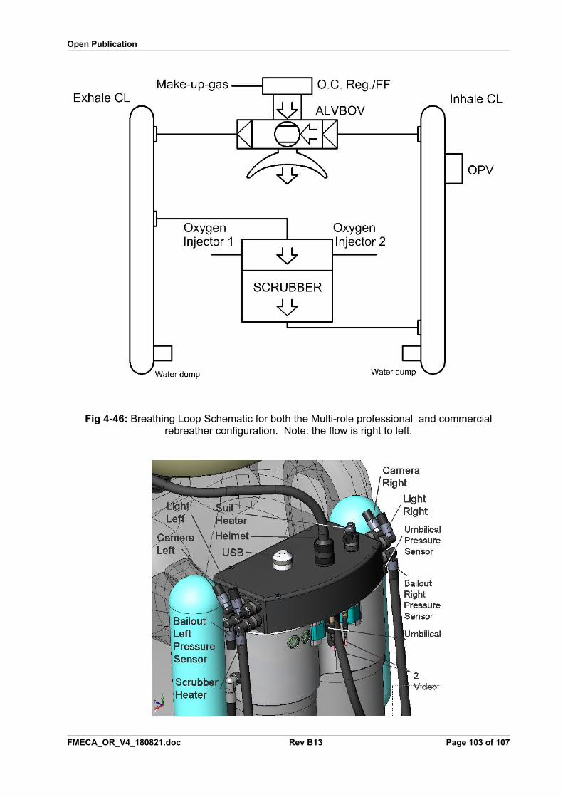
Open Publication
Fig 4-46: Breathing Loop Schematic for both the Multi-role professional and commercialrebreather configuration. Note: the flow is right to left.
FMECA_OR_V4_180821.doc Rev B13 Page 103 of 107
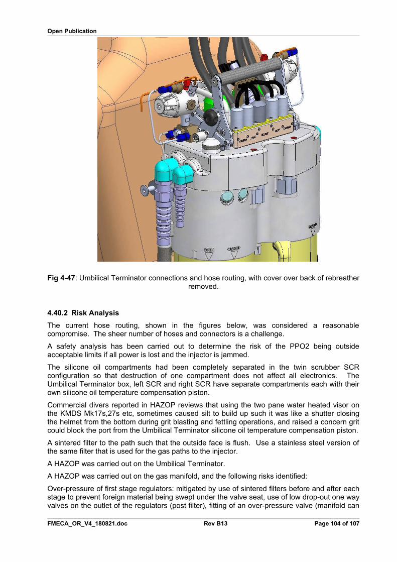
Open Publication
Fig 4-47: Umbilical Terminator connections and hose routing, with cover over back of rebreatherremoved.
4.40.2 Risk Analysis
The current hose routing, shown in the figures below, was considered a reasonablecompromise. The sheer number of hoses and connectors is a challenge.
A safety analysis has been carried out to determine the risk of the PPO2 being outsideacceptable limits if all power is lost and the injector is jammed.
The silicone oil compartments had been completely separated in the twin scrubber SCRconfiguration so that destruction of one compartment does not affect all electronics. TheUmbilical Terminator box, left SCR and right SCR have separate compartments each with theirown silicone oil temperature compensation piston.
Commercial divers reported in HAZOP reviews that using the two pane water heated visor onthe KMDS Mk17s,27s etc, sometimes caused silt to build up such it was like a shutter closingthe helmet from the bottom during grit blasting and fettling operations, and raised a concern gritcould block the port from the Umbilical Terminator silicone oil temperature compensation piston.
A sintered filter to the path such that the outside face is flush. Use a stainless steel version ofthe same filter that is used for the gas paths to the injector.
A HAZOP was carried out on the Umbilical Terminator.
A HAZOP was carried out on the gas manifold, and the following risks identified:
Over-pressure of first stage regulators: mitigated by use of sintered filters before and after eachstage to prevent foreign material being swept under the valve seat, use of low drop-out one wayvalves on the outlet of the regulators (post filter), fitting of an over-pressure valve (manifold can
FMECA_OR_V4_180821.doc Rev B13 Page 104 of 107
Open Publication
withstand 300 bar, cracking pressure of over-pressure valve is bar bar above normal injectoroperating pressure (and 5 bar above normal intermediate pressure). Injector pressure limit is140 bar: two injectors provided on isolated circuits. A KMDS One-circle one-way valve preventsflow of bail out gas (FO2 23%) into the diver’s helmet.
The ALV and BOV have been merged into one.
The BOV provides gas direct into helmet.
The currents used in welding and burning operations can be so great, that chrome is strippedfrom the brass of KMDS Mk17 helmets. Ensure the Umbilical Terminator box is shielded andtested in these extreme current densities. Magnetic effects may be dominant.
The original plastic chosen was Kynar, which is a liquid crystal acting as a good electrolyte.This provide further protection from high current densities by forming a Faraday cage aroundthe electronics, providing a good solution fitting the ALARP principle but the shrinkage andmechanical properties proved to be too problematic during moulding. A change was made to aspecial formulation of PP, which is free of plasticiser and softeners, but has non-toxic additivesto provide the required characteristics. However PP is also difficult to mould in complexsections, and it was found the plastic age hardened rapidly causing failures. This led to blackASA being used. Neither PP nor ASA have the electrolytic properties of Kynar so all EMC testswere performed using PP and ASA.
4.40.3 Failure Mode Analysis
The entire FMECA Volume 6 applies.
The gas manifold has been the subject of a dedicated HAZOP study, identifying risks, andmitigating factors as listed above.
FMECA_OR_V4_180821.doc Rev B13 Page 105 of 107
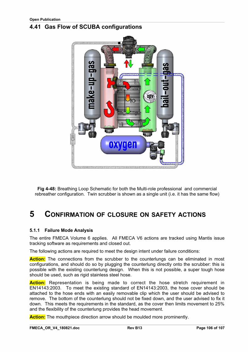
Open Publication
4.41 Gas Flow of SCUBA configurations
Fig 4-48: Breathing Loop Schematic for both the Multi-role professional and commercialrebreather configuration. Twin scrubber is shown as a single unit (i.e. it has the same flow)
5 CONFIRMATION OF CLOSURE ON SAFETY ACTIONS
5.1.1 Failure Mode Analysis
The entire FMECA Volume 6 applies. All FMECA V6 actions are tracked using Mantis issuetracking software as requirements and closed out.
The following actions are required to meet the design intent under failure conditions:
Action: The connections from the scrubber to the counterlungs can be eliminated in mostconfigurations, and should do so by plugging the counterlung directly onto the scrubber: this ispossible with the existing counterlung design. When this is not possible, a super tough hoseshould be used, such as rigid stainless steel hose.
Action: Representation is being made to correct the hose stretch requirement inEN14143:2003. To meet the existing standard of EN14143:2003, the hose cover should beattached to the hose ends with an easily removable clip which the user should be advised toremove. The bottom of the counterlung should not be fixed down, and the user advised to fix itdown. This meets the requirements in the standard, as the cover then limits movement to 25%and the flexibility of the counterlung provides the head movement.
Action: The mouthpiece direction arrow should be moulded more prominently.
FMECA_OR_V4_180821.doc Rev B13 Page 106 of 107
Open Publication
Action: After consideration of fatal accident reports and multiple incident reports, then applyingthe ALARP principle, this review rejects the whole concept of a mouthpiece as meetingEN61508 and SIL 3 levels and requires that the project introduce a Bail Out Valve (BOV) intothe mouthpiece as standard. The ALV should be the same valve as the BOV to ensure that anyfailure of the valve is detected before there is an emergency requiring bail out.This was done: the ALVBOV was introduced to the design.
Action: After consideration of fatal accident reports and multiple incident reports, in light thatthe mouthpiece opening determines the overall Work Of Breathing (the hoses and scrubberhave a Work Of Breathing less than that through the diver’s mouth), the review also rejects themouthpiece as complying with EN61508 at SIL 3 level. Applying the ALARP principle, theproject could support a Work Of Breathing which is effectively zero, i.e that is less than thatthrough the diver’s mouth, by enlarging the bore of the mouthpiece to more than 700sqmm.This was done for the commercial diver: a SCUBA mouthpiece causes jaw ache if opened upmore than 8mm at the diver’s teeth.
Action: The PFD Windows should be fixed using Loctite thread fixing to prevent a userunscrewing the PFD window. All other screws are Loctite sealed already in production.
Action: The PFD windows should be replaced by clear Grilamid 3L plastic, injection moulded.
Action: To mould a silicone shroud around the bottom of the scrubber, and preferably the topas well, to prevent damage from a mechanical impact equivalent to a 3m drop onto a hardsurface.
Action: Add a sintered filter to the path such that the outside face is flush. Use a stainless steelversion of the same filter that is used for the gas paths to the injector.
Action: DL to measure the amount of energy lost at the maximum operating depth we are designing to (600m). This will involve using the rebreather at 61bar, with the breathing machine, and heating the gas from the breathing machine with known energy, and measuring the gas coming back to the machine. The sea water will be 4C.
Action: Set the maximum operating depth for the present, at the point at which the gas heatingwould have to move from a SIL 0 project to a higher SIL level, or the U101 and EN14143:2003WOB limits, whichever is the lower.
Action: HAZOP will be carried out on the Umbilical Terminator at the next joint safety meeting:this was carried out.
Action: Consider merging ALV and BOV into one: carried out with the ALVBOV.
Action: BOV should be freeflow direct into helmet: both OSEL options provide this.
Action: The scrubber cartridge seal was subject ot a separate review and found to be optimal.
Action: A joint safety review should be carried out of this particular solution, with aconsideration of the commercial implications using the ALARP principle.
All these actions have been implemented as of Rev B7 of this document.
FMECA_OR_V4_180821.doc Rev B13 Page 107 of 107