MECHANICAL EVALUATION OF PLATE WORKING LENGTH IN …
64
1 MECHANICAL EVALUATION OF PLATE WORKING LENGTH IN A CANINE FEMORAL MODEL By PEINI CHAO A THESIS PRESENTED TO THE GRADUATE SCHOOL OF THE UNIVERSITY OF FLORIDA IN PARTIAL FULFILLMENT OF THE REQUIREMENTS FOR THE DEGREE OF MASTER OF SCIENCE UNIVERSITY OF FLORIDA 2012
Transcript of MECHANICAL EVALUATION OF PLATE WORKING LENGTH IN …

1
MECHANICAL EVALUATION OF PLATE WORKING LENGTH IN A CANINE FEMORAL MODEL
By
PEINI CHAO
A THESIS PRESENTED TO THE GRADUATE SCHOOL OF THE UNIVERSITY OF FLORIDA IN PARTIAL FULFILLMENT
OF THE REQUIREMENTS FOR THE DEGREE OF MASTER OF SCIENCE
UNIVERSITY OF FLORIDA
2012

2
© 2012 Peini Chao

3
To my family.

4
ACKNOWLEDGMENTS
First, I would like to thank all the people that have contributed to the work described
in this thesis.
Dr. Antonio Pozzi as my advisor and mentor has been an inalienable part of this
project. His perpetual energy and enthusiasm in clinics and research had motivated me
through this research journey. He gave me the confidence and all the support, enabled
me to get through every difficulty in front of me.
I would like to acknowledge my thesis committee members. The valuable advice
from Dr. Daniel Lewis, always pointed out the key points. Without his support I couldn't
have achieved a milestone. I gratefully thank Dr. Bryan Conard for providing me major
support, both in knowledge and in techniques, of engineering science. Dr. MaryBeth
Horodyski’s help in statistics was really precious in this thesis.
Additionally, I appreciate Dan Barousse and Debby Sundstrom for their important
experience sharing and all the assistance in every little detail in this study. Last but not
the least, this thesis would be incomplete without mentioning my parents: Shereen Lu
and Pan-Hwa Chao. Their unconditional support could only be cherished by providing
them a good research work. My big brother, Josh Chao has been another powerful
support during this whole time. Being my second family here, James Wang and
Ting-Bing Wu has not only guided me through many difficulties, but also replaced them
with fun and joy.

5
TABLE OF CONTENTS page
ACKNOWLEDGMENTS .................................................................................................. 4
LIST OF FIGURES .......................................................................................................... 6
LIST OF ABBREVIATIONS ............................................................................................. 7
ABSTRACT ..................................................................................................................... 8
CHAPTER
1 INTRODUCTION .................................................................................................... 10
2 BACKGROUND ...................................................................................................... 12
Basic Mechanics of Materials ................................................................................. 12
Force, Deformation, Stress and Strain ............................................................. 12 Stiffness............................................................................................................ 13 Fatigue Failure ................................................................................................. 16
Applied Biomechanics............................................................................................. 17 Biomechanics of Fracture Healing .................................................................... 17
Bone Healing under Conditions of Absolute and Relative Stability ................... 20 Factors Affecting Stiffness of the Plate-Bone Construct ................................... 23
Choosing the type of plate: locking versus non-locking plates ................... 23 Choosing the length of the plate ................................................................ 26 Effect of the position of screw placement in the plate ................................ 27
3 EXPERIMENT ........................................................................................................ 35
Effect of Plate Working Length on Plate Stiffness and Cyclic Fatigue Life in a Cadaveric Femoral Gap Model Stabilized with a 12-hole 2.4 mm LCP ............... 35
Specimen Preparation ...................................................................................... 36 Mechanical Testing .......................................................................................... 38
Data and Statistical Analysis ............................................................................ 39 Results .................................................................................................................... 40
Discussion .............................................................................................................. 42
4 CONCLUSION ........................................................................................................ 48
LIST OF REFERENCES ............................................................................................... 54
BIOGRAPHICAL SKETCH ............................................................................................ 64

6
LIST OF FIGURES
Figure page 2-1 Load-deformation curve ...................................................................................... 29
2-2 Load-deformation curves of three different material: bone, glass and metal. ..... 30
2-3 Area moment of inertia illustration ...................................................................... 31
2-4 Area moment of inertia between different implants ............................................. 32
2-5 Fatigue behavior in an S/N curve ....................................................................... 33
2-6 Absolute stability affects bone healing ................................................................ 34
2-7 Relative stability affects bone healing ................................................................. 34
3-1 Testing constructs of long and short plate working length stabilization techniques. ......................................................................................................... 46
3-2 Mean ± SD values of construct axial stiffness (N/mm) between long and short plate working length stabilization techniques ...................................................... 46
3-3 Photographs and free body diagrams of a long and short plate working length constructs before and after load to failure test .................................................... 47

7
LIST OF ABBREVIATIONS
ANOVA ANALYSIS OF VARIANCE
AO-ASIF ARBEITSGEMEINS CHAFT FÜR OSTEOSYNTHESEFRAGEN – ASSOCIATION
FOR THE STUDY OF INTERNAL FIXATION
DCP DYNAMIC COMPRESSION PLATE
LCP LOCKING COMPRESSION PLATE
MTS MATERIAL TESTING MACHINE
SD STANDARD DEVIATION

8
Abstract of Thesis Presented to the Graduate School of the University of Florida in Partial Fulfillment of the
Requirements for the Master of Science
MECHANICAL EVALUATION OF PLATE WORKING LENGTH IN A CANINE FEMORAL MODEL
By
Peini Chao
August 2012
Chair: Antonio Pozzi Major: Veterinary Medical Sciences
To compare the bending stiffness, gap motion, cyclic fatigue life and load to failure
of plated dog femora stabilized using either a short or long plate working length
technique. Contralateral femora were randomly assigned to one of two stabilization
techniques: femora plated with 12-hole 2.4 mm LCP using 2 screws per fracture
segment resulting in a long working length or femora plated with the same LCP using 5
screws per fracture segment resulting in a short working length. Constructs stiffness and
yield load in load to failure test were compared between techniques using a paired-t test.
Bending stiffness and gap motion during cyclic testing were compared between
techniques using a 2 x 9 or 2 x 11 (technique x cycle) within subjects repeated measures
ANOVA; a p<0.05 was considered significant.
Construct stiffness did not differ significantly between techniques. Implant failure did
not occur in any of the plated femora during cycling. Mean ± SD of gap motion of long
(0.2 ± 1 mm) and short plate working length constructs (0.1± 0.6 mm) were not
significantly different during cyclic test. Mean ± SD yield load in short plate working
length (654.5 ± 149.0 N) technique were significantly higher than in long plate working
length (452.9 ± 63.4 N) technique. Plate working length had no effect on stiffness, gap

9
motion and resistance to fatigue in our testing model. Although short plate working length
tends to increase the resistance to failure; the yield loads for both stabilization
techniques were within physiologic range.

10
CHAPTER 1 INTRODUCTION
Over the past two decades, there has been a paradigm shift regarding the approach
to internal fixation of long bone fractures with bone plates. The prerequisite for open
anatomic reduction and rigid stabilization has given way to less invasive application of
more flexible constructs with bridging plates 1-3. The use of locking technology allows the
plate to function as an internal fixator 4-9.Surgeons can choose among a variety of
implants to allow a more or less flexible bone-plate construct 8,10-29. Furthermore, the
design and type of plate can play a primary role in fracture reduction 12,26,29-32. Whereas
plates with a compression or neutralization function require precise reconstruction and
rigid stabilization, plates applied in a bridging fashion circumvent the need for anatomical
reduction33. Bridging plates are often applied utilizing indirect reduction techniques,
which mitigate the degree of iatrogenic trauma while preserving fracture vascularity
1,2,4,32,34-37. Understanding the basic biomechanical principles of surgical stabilization of
fractures is essential for developing an appropriate preoperative plan as well as making
prudent intra-operative decisions.
The objective of this chapter is to provide basic biomechanical knowledge essential
to understand the complex interaction between the mechanics and biology of fracture
healing. It is clearly understood that careful soft-tissue handling is very important in
preserving blood supply to the injured bone. However, the type of healing and the
outcome can be influenced by several mechanical factors, which depend on the
interaction between bone and implant 31,38-41. The main objective for utilizing less
invasive fracture stabilization techniques is to optimize the healing potential by achieving
a symbiotic balance between the biologic and the mechanical factors of fracture fixation.

11
Thus the surgeon should understand the mechanical principles of fracture fixation and
be able to choose the best type of fixation for each specific fracture.

12
CHAPTER 2 BACKGROUND
Basic Mechanics of Materials
Force, Deformation, Stress and Strain
The strength of a material depends on its ability to resist failure from an applied stress.
Stress is the force acting on an area, and can be compressive, tensile or shear stress.
The unit for stress is Newtons per square millimeter (N/mm2) 42. When stress is applied
to an object, deformation may occur. Thus, the term deformation is used to describe the
change in shape or size of an object due to an applied force 42. Depending on the size,
shape, material of the object, and the force applied, various type of deformation may
occur. Elastic deformation is reversible: an object may deform when subjected to an
applied load, but the object returns to its original shape once the load is released. Plastic
deformation in contrast is irreversible and the object does not return to its original shape
once the applied load is released. Another type of deformation, unique to ductile metals,
is metal fatigue. This phenomenon describes the progressive formation of cracks which
develop in a material subjected to numerous cycles of elastic deformation 43. The
different phases of deformation of an object are readily illustrated by plotting a
load-deformation curve (Figure 2-1), which shows the relationship between stress (force
applied) and strain (deformation) of an object 42. The elastic range of the curve ends
when the object reaches its yield strength and begins to undergo permanent plastic
deformation. If continued load is applied, material failure may occur in the form of a
fracture, or the object may just continue to undergo further plastic deformation. When
applying these concepts to fracture fixation, a bone plate should function within the
elastic region, and should not be subjected to loads which exceed the plate’s yield

13
strength. Therefore, yield strength is a very useful parameter for comparing the
mechanical properties of different plates; however, this information is most meaningful
when the applied load in vivo is known.
The term strain is used in order to give a more standardized and quantified description
of material deformation resulting from an applied stress. Strain is defined as the ratio
between the measured changes in length during loading to the original length. Strain
refers to a change in shape of a specified segment which undergoes either elongation or
shortening. Strain is a unitless ratio (length over length), but is commonly reported in
units of microstrain, so that a strain of 0.01 (1%) would be 10,000 microstrain.
Interfragmentary strain is a term used to describe the mechanical enviroment within a
fracture gap subjected to axial loading 44,45. Interfragmentary strain is defined as the
relative change in the fracture gap divided by the original width of the fracture gap
1,41,44,45.
Stiffness
A material’s or a structure’s stiffness defines its ability to resist deformation resulting
from an applied force 42. For so-called linear elastic materials (such as bone), the elastic
region of the load-displacement curve is linear, because the deformation is directly
proportional to the applied load (Figure 2-2). The slope of the linear portion of the
load-displacement curve is known as Young’s modulus, or the modulus of elasticity and
is a measure of the stiffness of the material. Elasticity is a characteristic of a material or
object to return to its previous shape after an applied load is released. Plasticity in
contrast to elasticity describes residual deformation of a material or object as a result of
loading and is an unrecoverable status. More elastic materials can usually sustain
considerable plastic deformation, while more brittle materials will fracture at relatively low

14
loads. As an example, the load-deformation curves of the same object with 3 different
material such as bone, glass and metal would look significantly different from each other
(Figure 2-2) The more brittle rigid body such as bone undergo minimal plastic
deformation before reaching the failure point, while metal has a linear elastic portion of
the curve, indicating linearly elastic behavior. The long plastic region of the metal
indicates that this material deforms extensively before failure.
Another concept that helps elucidate the biomechanical characteristics of orthopedic
implants such as plates, screws, intramedullary pins and interlocking nails is the area
moment of inertia 46. The bending stiffness of an object (such as an orthopedic implant)
depends on the bending moment (the force applied to the plate), which is the product of
the elastic modulus of the object material and the area moment of inertia of the
cross-section of the object (Figure 2-3). The area moment of inertia describes the
capacity of the cross-sectional profile of an object to resist bending. The greater the area
moment of inertia, the less a structure will deflect (higher bending stiffness) when
subjected to a bending load. Area moment of inertia is dependent on an object’s
cross-sectional geometry (Figure 2-3). The further the object’s mass is located from the
neutral axis, the larger the moment of inertia. For this reason area moment of inertia is
always considered with respect to a reference axis, in the X or Y direction, which is
usually located at the center of an object’s cross section. The area moment of inertia of
an object having a rectangular cross-sectional profile, such as a plate, can be derived by
the equation bh3/12 where b is the base and h is the height. The base dimension is
oriented parallel to the axis of the moment of inertia and height is defined as the
dimension parallel to the direction of the applied load. Thus the location a plate is

15
positioned on a bone and the plate’s orientation to applied bending loads can have a
profound effect on a construct’s bending stiffness (Figure 2-3). This effect becomes even
more important when fractures are not anatomically reconstructed and plates are applied
in bridging fashion. Understanding the area of moment of inertia is important when
comparing the mechanical properties of implants of different shape and size but similar
metal, such as in case of an interlocking nail, a bone plate and a plate-rod construct
(Figure 2-4). As shown in the calculation, the interlocking nail has the largest area of
moment of inertia because of its large diameter. It should also be noted that the area of
moment of inertia of an intramedullary pin occupying 40% of the medullary canal has a
significant contribution to the total area of moment of inertia of a plate-rod construct
(Figure 2-4), justifying its recommendation as bridging implants for comminuted fractures
18,47. Another approach to fixation of a fracture with a gap is to increase the size of the
plate. As shown in the calculation (Figure 2-4), a 3.5 mm broad LCP has an area of
moment of inertia 3 times larger than a 3.5 mm LCP and almost twice larger than a 3.5
mm LCP combined with an intramedullary rod.
Although the stiffness of a plate is an important predictor of the implant’s behavior
under applied load, the mechanical properties of the combined plate-bone construct are
more relevant to predict the type of fracture healing 14. For this reason, it is important to
distinguish between implant stiffness, structural stiffness of the construct and stiffness
across the fracture gap 8,48-50. The construct stiffness is determined by numerous
variables, including the plate’s composition and geometry, the distance between plate
and bone surface, plate length, type of screws and the plate working length
4,8,10,16,27,28,51-58. The plate working length is defined as the distance between the proximal

16
and distal screws closest to the fracture 34. The gap stiffness is derived from the
load-displacement curve describing the mechanical behavior of the tissue forming at the
fracture gap. Interfragmentary strain is defined as the relative displacement of the
fracture gap ends divided by the initial fracture gap width 44,59. For this reason the initial
fracture gap is an important factor determining the stiffness of the construct. The
relationship between gap strain and fracture healing has been extensively studied and
will be discussed in the next section.
Fatigue Failure
Mechanical failure of plates can be broadly divided into three categories: plastic, brittle
and fatigue failure. Plastic failure describes failure of an implant to maintain its original
shape, resulting in a loss of reduction and alignment and clinical failure. Brittle failure, an
unusual course of implant failure, results from a defect in design or metallurgy. Fatigue
failure occurs as a result of repetitive loading at an intensity considerably below the
normal yield strength of the implant 42,43. Cyclic loading can lead to the formation of
microscopic cracks that can propagate until these cracks reach a critical size which
cause sudden failure of the implant. Although the propagation of the microcracks can
take a considerable amount of time, there is typically very little, if any, warning preceding
ultimate failure. Crack formation is commonly initiated at a “stress concentrator” or a
“stress riser” such as a scratch on the plate or at a location where there is a change in
the plate’s cross sectional geometry, such as a screw hole. The stress that is focused in
these areas can be relatively higher than the average stress of the whole construct.
Therefore, local material failure can occur at one of these stress concentrators and
eventually propagate through the implant 43. The number of cycles required to cause
fatigue failure decreases as the magnititude of the stress increases. Fatigue failure is a

17
genuine concern following fracture stabilization because of the high number of repetitive
loads that implants are subject to during the post-operative convalescent period.
Therefore, every surgeon must be cognizant that they have entered the proverbial race
between fatigue failure of the implant and healing of the fracture, when repairing any
fracture.
Cyclic testing is useful to detect the performance of an implant in resisting fatigue
failure. In general, a predetermined stress or strain limit will gradually be reached while
applying a cyclic bending moment or tensile/compressive force on a construct. The
principle of this type of testing is to determine the total number of loading cycles that a
particular construct can withstand before failing. A construct’s fatigue behavior can be
described in an S/N curve; in which the stress to failure, S, is plotted against the number
of cycles to failure, N (Figure 2-5) 42. A construct’s failure point is termed “allowable
stress”. Typically, a construct subjected to a small applied-stress can withstand a large
numbers of cycles and vice versa. However, the number of cycles to failure at a constant
stress level can be affected by many factors such as the material and the geometry of
the construct or the surrounding environment of the implant and the bone.
Applied Biomechanics
Biomechanics of Fracture Healing
Numerous studies have shown that the mechanical conditions affecting the fracture
site, principally the stability afforded by the fixation and the width of the fracture gap,
influence callus formation during the healing process 28,44,60-70. The process of bone
healing is dependent on numerous interactions between biologic and mechanical factors.
The type of injury, the location and configuration of the fracture, the magnitude of load
acting on the fracture as well as systemic factors, all play a role in the type and efficiency

18
of bone healing 41,60,71. Two principle concerns are whether there is adequate blood
supply as well as effective stability to allow a fracture to obtain union. If the local
circulation is adequate to support fracture healing, the pattern of bone healing is then
dependent on the surrounding biomechanical environment 41,44,60,65,68-71. Several
mechano-regulation theories of skeletal tissue differentiation have been developed that
predict many aspects of bone healing under various mechanical conditions 59,66-70,72. The
theory proposed by Perren is based on the interfragmentary strain present in the fracture
gap 44,59. This theory suggests that the type of tissue formed in a healing fracture gap is
dependent on the strain environment within the gap. The tissues that are stressed
beyond their ultimate strain could not form in the gap. If interfragmentary strain exceeds
100%, non-union will occur. Gap strains between 10 and 100%, allow for fibrous tissue
formation. Strains between 2 and 10% allow for cartilage formation and subsequent
endochondral ossification. Strains of less than 2% allow for direct bone formation and
primary fracture healing. Perren proposed that once any tissue formed, it would
progressively stiffen the fracture gap. In turn, the tissue formed in the gap would lead to
lower strains, which would allow formation of the next stiffer tissue and the cycle would
repeat until bone formed within the gap. An alternate theory relating mechanical stimulus
to fracture healing was proposed by Carter and Blenman which predicts that tissue
differentiation within the fracture gap is dependent on the magnitude and the type of local
stress, including hydrostatic pressure and octahedral shear stress 68,70,73. This theory
purports that the vascular supply to the tissues at the fracture site is the primary factor
determining tissue differentiation. With a good circulation in tissues, Carter and Blenman
proposed that fibrocartilage will form if high hydrostatic compressive stresses are

19
present. In an analysis of fracture healing, Carter and Blenman correlated compressive
hydrostatic stress with cartilage formation (chondrogenesis) whereas low hydrostatic
stress corresponded to bone formation (osteogenesis) 68-70. However, the relationship
between the ossification pattern and the loading history was described only qualitatively
and not quantitatively. More recently, Claes and Heigele have proposed and tested the
quantitative tissue differentiation theory, which relates the local tissue formation to the
local stress and strain in a fracture gap 66. The results regarding the global strain and
hydrostatic pressure fields correlate with the principal results of Carter and Blenman. In
contrast to Carter and Blenman’s work 68,70,73 the quantitative tissue differentiation theory
is based on the assumption that new bone formation only occurs on existing bony
surfaces and under defined ranges of strain and hydrostatic pressure. The tissue
differentiation hypothesis predicts intramembranous bone formation will proceed once
interfragmentary strain become less than 5% while endochondral ossification can occur
at interfragmentary strains approximating 15% in a diaphyseal fracture, which obtain
union by secondary bone healing 45,66. Another recent theory on mechanobiology of
fracture healing proposed a model dependent on two biophysical stimuli: tissue shear
strain and interstitial fluid flow 67. The rationale for this approach is that fluid flow
increases the biomechanical stress and deformation on the cells above that generated
by the strain of the collagenous material 67.
Although Perren’s theory on interfragmentary strain is important to understand the
concept of tissue mechanobiology at the fracture gap, several studies have
demonstrated that gap strain higher than 2% is tolerated and that the strain patterns
within a fracture gap are heterogenous 74,75. It is well accepted that interfragmentary

20
movement is the most important biomechanical factor in fracture healing, but it is not
known which is the optimal range for callus formation and bone healing.
Bone Healing under Conditions of Absolute and Relative Stability
The term stability is defined as the load-dependent displacement of the fracture
surfaces. Stability in osteosynthesis covers a spectrum from minimal to absolute.
Absolute stability is only present when there is no displacement of the stabilized fracture
segments under loading (Figure 6). Absolute stability is achieved by 1) applying a
compressive pre-load that exceeds the traction force acting at the segments, and by 2)
counteracting the shear forces acting on the fracture surfaces with friction. The
elimination of relative motion between the bone segments results from the application of
interfragmentary compression and requires anatomic reduction 9. Placement of a lag
screw is an excellent example of a fixation that can provide absolute stability (Figure
2-6). In vivo experiments have shown that a lag screw can produce high compressive
forces (>2,500 N) across a fracture 76. While absolute stability was originally thought to
be necessary for successful management of most fractures, current thinking suggests
that absolute stability is only obligatory when stabilizing articular fractures and only when
interfragmentary compression can be achieved without inducing excessive iatrogenic
damage to blood supply and surrounding soft tissues 9. Limiting soft tissue trauma is an
essential tenant of any fracture repair even when performing a direct open reduction,
efforts should be made to minimize iatrogenic trauma to the regional soft tissues and the
periosteum.
Fractures stabilized under conditions of absolute stability will heal by primary or direct
fracture healing, if anatomically reduced 77-79. Since there is no motion at the fracture
site, there will be negligible callus formation. The fracture heals through the formation of

21
osteonal cutting cones and Haversion remodeling of the compressed cortical bone 78,79.
Direct bone healing can be further subdivided into two types based on the width of the
fracture gap. Contact healing occurs when the ends of the bone segments are in direct
contact, the gap between the two bone segments is less than 0.01 mm and when
interfragmentary strain is less than 2% 78. If the fracture gap is larger but does not
exceed 1 mm, and an interfragmentary strain again is less than 2%, gap healing will
occur, in which intramembraneous bone will be formed directly in the fracture gap 44. In
both types, a process called Haversian remodeling begins with osteoclastic resorption
that result in resorption cavities formed by groups of osteoclasts also called a cutting
cone 79. Bone resorption is followed by osteoblast activity. The osteoblasts line the
resorption cavities and produce layers of new bone. The resorption cavity is filled in with
new bone to form a new osteone. Gap healing results from the development of lamellar
and cortical bone forming from granulation tissue in small gaps 78,79. Intramembranous
bone formation occurs during direct bone healing; the surrounding environment can
impose up to 5% strain as long as it allows the differentiation of mesenchymal cells into
osteoblasts..
Relative stability is a condition where an acceptable amount of interfragmentary
displacement compatible with fracture healing is present (Figure 2-7) 80. Relative stability
involves placement of implants that provide somewhat flexible fixation which allow an
acceptable degree of fracture segments displacement. Fixation modalities that can be
employed to provide relative stability include plates, interlocking nails and external
fixators applied in bridging fashion to span a bone defect 71,81.
22
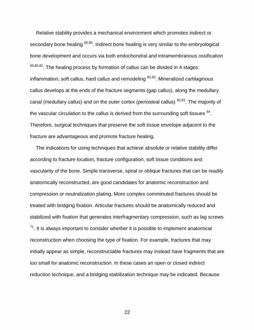
Relative stability provides a mechanical environment which promotes indirect or
secondary bone healing 65,80. Indirect bone healing is very similar to the embryological
bone development and occurs via both endochondral and intramembranous ossification
65,80,82. The healing process by formation of callus can be divided in 4 stages:
inflammation, soft callus, hard callus and remodeling 82,83. Mineralized cartilaginous
callus develops at the ends of the fracture segments (gap callus), along the medullary
canal (medullary callus) and on the outer cortex (periosteal callus) 82,83. The majority of
the vascular circulation to the callus is derived from the surrounding soft tissues 84.
Therefore, surgical techniques that preserve the soft tissue envelope adjacent to the
fracture are advantageous and promote fracture healing.
The indications for using techniques that achieve absolute or relative stability differ
according to fracture location, fracture configuration, soft tissue conditions and
vascularity of the bone. Simple transverse, spiral or oblique fractures that can be readily
anatomically reconstructed, are good candidates for anatomic reconstruction and
compression or neutralization plating. More complex comminuted fractures should be
treated with bridging fixation. Articular fractures should be anatomically reduced and
stabilized with fixation that generates interfragmentary compression, such as lag screws
71. It is always important to consider whether it is possible to implement anatomical
reconstruction when choosing the type of fixation. For example, fractures that may
initially appear as simple, reconstructable fractures may instead have fragments that are
too small for anatomic reconstruction. In these cases an open or closed indirect
reduction technique, and a bridging stabilization technique may be indicated. Because

23
the success of the technique depends on the precision of the reduction, critical
preoperative planning should always be performed.
Factors Affecting Stiffness of the Plate-Bone Construct
The stiffness of the bone-plate construct is a major determinant of the mechanism and
progression of bone healing 1,28,50,68,69. There are several parameters in addition to the
material properties of the implants that need to be considered when applying a bone
plate. Understanding the effect of plate type, size, length, position, screw type and screw
placement is important because successful fracture healing depends on appropriate
fixation stability 53,55,57,58,85-88. Furthermore a multitude of plate types and concepts have
been described and proposed in the last decade, in an attempt to decrease the
complications and improve the reliability of bone plating. The development of new
implants and techniques have followed a shift in emphasis of AO philosophy from
obtaining anatomic reconstruction and absolute stability to obtaining anatomic alignment
and appropriate stability utilizing more atraumatic application techniques 9,71. Concurrent
with this change in emphasis in internal fixation, newer implant systems such as internal
fixators, locking plates or angular stable devices, have been developed to improve
bone-plating technique 9. Understanding the mechanical properties of locking plates and
conventional plates is important for choosing an appropriate implant system.
Choosing the type of plate: locking versus non-locking plates
Gautier and Sommer recently presented prudent guidelines that may improve the
individual learning curve of surgeons who are less familiar with locking plates 31.
However, it is important to understand the concepts behind these recommendations for
successful utilization of the vast choice of plates available 10,27. There are distinct
principal biomechanical differences between bridging plates and locked internal fixators

24
with regard to load transfer through a fractured bone. In conventional compression plate
constructs or nonlocking bridging plate constructs, fixation stability is limited by the
frictional force generated between the plate and the bone. This force is created by axial
screw forces and the coefficient of friction between the plate and the bone 8,89. If the
force exerted on the bone while the patient is ambulating exceeds the frictional limit,
relative shear displacement will occur between the plate and the bone, causing a loss of
reduction between the bone fragments, or loosening of the screws, or both. Conventional
plates, including dynamic compression plates (DCP) 90 and limited contact dynamic
compression plates (LC-DCP) 91 allow compression of bone fragments utilizing the
dynamic compression holes. In a transverse fracture that has been anatomically
reduced, stability can be further increased by utilizing the plate to generate
interfragmentary compression between the ends of the fracture segments when the
screws are inserted eccentrically at the end of the oval hole (away from the fracture), the
lower hemi-spherical part of the screw head will contact the dynamic compression incline
of the compression hole. This interaction between the screw head and the compression
incline results in sliding of the screw down the incline hole in the plate, producing
compression of the ends of the fracture segments during screw tightening 90,91.
Locking plates differ from non-locking plates because stability is not dependent on the
frictional forces generated at the bone-plate interface. The first plate that functioned as
an internal fixator (Zespol system) was developed in 1970 in Poland 92. Since then, a
number of locking plates have been developed that utilize the concept of angular
stability. These implants consist of a plate and locking head screws which together act
as an internal fixator. Locking the head screw into the hole confers axial and angular

25
stability of the screw, relative to the plate. Because the stability of the construct does not
depend on frictional forces generated between plate and bone, the bone-screw threads
are unlikely to strip during insertion. The fixed-angle connection between the screw and
the plate clearly affords improved long-term stability. Plate failure by “pull-out” is unlikely
because the screws cannot be sequentially loaded or pulled out 9,25,93.
Locking plates have both mechanical and biological advantages. The periosteal blood
supply beneath the plate is not compromised because compression between plate and
bone does not occur. Preservation of the periosteal vasculature may improve healing
and decrease the risk of cortical bone necrosis and infection 81. Another advantage is
that the plate does not need to be perfectly contoured, because the bone is not “pulled
towards” the plate while tightening the screw. For this reason, locking plates are often
used for minimally invasive plate osteosynthesis (MIPO), which involves closed
reduction and percutaneous fixation of the fracture 34 In press,35,94,95. Several different
locking plate systems are available. Some plates may have combination holes that allow
placement of a locking screw or a conventional non-locking screw in either a
compressive or neutralize fashion or a locking screw 9,96,97.
Several biomechanical studies have compared locking and non-locking plates in
dogs. These studies have conflicting results. While some studies demonstrated that
locking plate constructs were stiffer than non-locking plate constructs when tested in
axial compression, torsion, and bending 16,22,51,89,96,98-104, others did not find any
significant differences between the two 12,20,26,29,54,86,98,105-108. The most consistent finding
has been that locking plates perform better than non-locking plates in osteoporotic bone

26
4,89,99,109. The biomechanical advantages of locking plates may be less evident in normal
bone.
Choosing the length of the plate
The selection of an appropriate length plate is a very important step in the
preoperative plan. Appropriate plate length is dependent on the location and
configuration of the fracture as well as the intended functional application of the plate. In
bridge plating, longer plates lower the pullout force acting in screws due to an
improvement of the working leverage for the screws and better distribution of the
bending forces along the plate 31. The theoretical advantage of using a longer plate
without placing screws in the center portion of the plate is supported by several
biomechanical studies. Sander et al compared three different plate lengths, six-, eight- or
ten-hole 3.5 mm dynamic compression plates fixed on dog cadaveric ulnae, tested in
four-point bending to failure. The results revealed that ten-hole plates with four screws
(widely spread on the fracture fragment), failed at higher peak loads than six-hole plates
with six screws, supporting the recommendation tha longer plates with fewer screws
provide superior bending strength than shorter plates with a greater number of screws 88.
In another study, Weiss evaluated eight- and ten-hole 3.5 mm locking compression
plates used to stabilized human cadaveric ulnas. This study found that 10-hole plates
secured with two non-locking screws placed in a near-far configuration on either side of
the fracture demonstrated an increased yield strength compared to 8-hole plates with the
same number of screws and configuration in four-point bending to failure 86. Iatrogenic
trauma associates with the open application of a long plate can be substantially mitigated
by using less invasive application techniques such as MIPO.

27
Two values have been used to determine the length of the plate to be used. The plate
span ratio is a quotient derived by dividing plate length by the segmental length of the
fracture. Based on guidelines developed for fracture fixation in man, the plate span
should be more than 2 to 3 in comminuted fractures and more than 8 to10 in simple
fractures 9. Plate-screw density is the quotient derived by dividing the number of screws
inserted by the number of holes in the plate. Empirically, values below 0.4-0.3 when
applied in simple fracture and value below 0.5-0.4 when applied in comminuted fracture
have been recommended 9,31. These guidelines were formulated for the application of
plates in human patients, and need to be evaluated in dogs.
Effect of the position of screw placement in the plate
In comminuted fractures which have not been reconstructed, stress is distributed over
the fracture gap and is dependent on the number and location of screws placed 9,53 in
addition to other factors. The lowest stress in the plate occurs when the screws are as
close as practical to the fracture 53. This, however, leads to the highest axial stiffness as
well as very small interfragmentary movements and strains beneath the plate. It has
been recommended to increase the plate working length to reduce axial stiffness of a
plate-bone construct 9,31,110; however, previous mechanical studies have yielded
conflicting results 53,87,111. Based on mechanical tests performed in our lab 34 we suspect
that the variability in the results amongst reported studies might be attributed on how the
plate is applied to the bone. In constructs which utilize non-locking plates, the contact
between the plate and the bone segments causes the bending moment to concentrate
between the end of the bone segments regardless the positioning of the screws.
Therefore, the functional plate working length does not correspond to the distance
between the screws placed closest to the fracture gap, but rather to the length of the

28
fracture gap. In contrast, the physical offset of a locking plate which is applied without the
bone and plate in intimate contact enables a locking plate to bend along the entire
segment of the plate between the two most centrally positioned screws.
More recent strategies to decrease the stiffness of locking plate-bone constructs
include new designs of locking screw that allow to increase the fracture gap micromotion
with axial loading 112-114. The goal of this novel approach to locking plate is to promote
more reliable healing, and prevent late failures observed in several clinical studies in
people 115-117. The far cortex locking screw has a smooth shaft with threads at the tip that
achieve purchase in only the far cortex 50,112,113,118. The smooth shaft of this screw
decreases the stiffness of the plating construct and allows greater callus compared to
standard locked implants 112. Another screw design attempting to combine the
advantages of locking screws and controlled axial micromotion is the dynamic locking
screw 114. This dynamic locking screw is composed of an outer sleeve with threads that
engage the bone and an inner pin with threads that lock to the plate. By allowing motion
between inner pin and the outer sleeve, the dynamic compression screws reduced the
axial stiffness by 16% 114.

29
Figure 2-1. A load-deformation curve shows the relationship between stress (force applied) and strain (deformation) of an object. The elastic range (A-B) of the curve ends when the object reaches its yield strength (B) and begins to undergo permanent plastic deformation (B-C). If continued load is applied, material failure may occur in the form of a fracture, or the object may just continue to undergo further plastic deformation.

30
Figure 2-2. The load-deformation curves of the same object with 3 different material: bone, glass and metal. More elastic materials can usually sustain considerable plastic deformation, while more brittle materials will fracture at relatively low loads. The more brittle rigid body such as bone undergo minimal plastic deformation before reaching the failure point, while metal has a linear elastic portion of the curve, indicating linearly elastic behavior. The long plastic region of the metal indicates that this material deforms extensively before failure.

31
Figure 2-3. The area moment of inertia describes the capacity of the cross-sectional profile of an object to resist bending. The greater the area moment of inertia, the less a structure will deflect (higher bending stiffness) when subjected to a bending load. Area moment of inertia is dependent on an object’s cross-sectional geometry.

32
Figure 2-4. Area moment of inertia is important when comparing the mechanical properties of implants of different shape and size but similar metal, such as in case of an interlocking nail, a bone plate and a plate-rod construct ( As shown in the calculation, the interlocking nail has the largest area of moment of inertia because of its large diameter. It should also be noted that the area of moment of inertia of an intramedullary pin occupying 40% of the medullary canal has a significant contribution to the total area of moment of inertia of a plate-rod construct, justifying its recommendation as bridging implants for comminuted fractures. Another approach to fixation of a fracture with a gap is to increase the size of the plate. As shown in the calculation, a 3.5 mm broad LCP has an area of moment of inertia 3 times larger than a 3.5 mm LCP and almost twice larger than a 3.5 mm LCP combined with an intramedullary rod.

33
Figure 2-5. A construct’s fatigue behavior can be described in an S/N curve; in which the stress to failure, S, is plotted against the number of cycles to failure, N. Typically, a construct subjected to a small applied-stress can withstand a large numbers of cycles and vice versa.

34
Figure 2-6. Absolute stability is only present when there is no displacement of the
stabilized fracture segments under loading. The elimination of relative motion between the bone segments results from the application of interfragmentary compression and requires anatomic reduction.
Figure 2-7. Relative stability is a condition where an acceptable amount of
interfragmentary displacement compatible with fracture healing is present.

35
CHAPTER 3 EXPERIMENT
Effect of Plate Working Length on Plate Stiffness and Cyclic Fatigue Life in a Cadaveric Femoral Gap Model Stabilized with a 12-hole 2.4 mm LCP
There are several factors that can affect the fatigue life of plated fracture construct.
In addition to the mechanical properties of the isolated plate, the location, type and
complexity of the fracture influence the load acting on the plate 8,17,31,55,85,88. Bridging
plates are often utilized in comminuted fractures to span a large segment of the fractured
bone which is not reconstructed, having a long segment of the plate unsupported by
screws 110. The distance between the proximal and distal screw in closest proximity to
the fracture is defined as the “working length” of the plate. Plate working length has been
shown to influence construct stiffness, plate strain and cyclic fatigue properties of the
plated constructs 57,85,87,111,119. The lack of load sharing between the stabilized bone
segments and the implants increases the risk of cyclic fatigue and potentiates early
failure of the implant 53,87. A mechanical study evaluating the mechanical endurance of
human femora stabilized with 14-hole broad 4.5 mm locking compression plates (LCP)
found that constructs with load sharing resisted 20 times more cycles than the constructs
with an 8 mm segmental diaphyseal gap 120.
Controversy still exists regarding the effect of plate working length on stiffness and
resistance to fatigue failure 53,58,85. Stoffel et al. reported that increasing the plate working
length by omitting one screw placed adjacent to the fracture in each of the major fracture
segments made a locking plating construct nearly twice as flexible when loaded in axial
compression and torsion 53. In contrast, Field et al. reported that omitting two screws
proximal and distal the fracture had no significant effect on either bending or torsional
stiffness of a conventional plate construct in a comparable bridge plating configuration 58.

36
Studies evaluating the effect of working length on the cyclic fatigue properties of plated
constructs have yielded inconsistent results 53,85,87. Stoffel et al. found that the constructs
with a shorter plate working length were more resistant to cyclic loading 53. Maxwell et al.
reported similar results when screw placement was evaluated in 3.5 mm dynamic
compression plates and limited contact dynamic compression plates applied in a fracture
gap model 111. Recent studies comparing the cyclic fatigue of plates applied with a short
and long working length found that the constructs with a longer working length withstood
more cycles before failure, although the differences between stabilization techniques
were not significant 85,87.
The purpose of the present study was to evaluate the effect of plate working length
on construct stiffness, gap motion and resistance to cyclic fatigue in dog femora with a
simulated fracture gap stabilized using a 12-hole 2.4 mm LCP. Our first hypothesis was
that constructs with a longer plate working length would be more flexible and have
greater gap motion than constructs with a shorter plate working length. The second
hypothesis was that constructs with a longer plate working length would withstand more
cycles before succumbing to fatigue failure than constructs with a shorter plate working
length. Materials and Methods
Specimen Preparation
This study was approved by the University of Florida Institutional Animal Care and
Use Committee. Ten pairs of femora were collected from adult dogs (mean ± SD: 17.9 ±
1.9 kg) that were euthanized for reasons unrelated to the study. Once all the soft tissues
were removed from the femurs, the bones were radiographed in order to exclude
specimens with osseous abnormality. The femora were then wrapped in saline-soaked

37
towels and stored at -20℃ until testing, at which time the bones were thawed to room
temperature. One femur from each dog was randomly assigned to the short plate
working length stabilization group. The contralateral femur was assigned to the long
plate working length stabilization group.
A 12-hole 2.4 mm LCP1 was contoured and clamped temporarily to the lateral surface
of each femur. Two lines, 10 mm apart were marked on the mid-diaphyseal region of the
bone adjacent to the central 2 holes of the plate. The plate was removed, and an
oscillatory saw was used to initiate two mid-diaphyseal partial osteotomies in the lateral
cortex of the femur at the marked locations. In the femora assigned to the long plate
working length stabilization group, the plate was affixed with one 2.4 mm locking and one
2.4 mm cortical screw placed at the ends of the plates, leaving eight empty holes in the
middle of the plate (Figure 3-1). The femora assigned to the short plate working length
stabilization group were fixed with one 2.4 mm locking and four 2.4 mm cortical screws in
each femoral segment, leaving two empty holes in center of the plate (Figure 3-1). All
screws had bicortical purchase and were placed in the same order. Cortical screws at
each end of the plate were placed first, followed by the locking screw in the second hole
and the remaining cortical screws. All screws were placed and hand-tightened by an
experienced board-certified surgeon (AP) in accordance with standard AO-ASIF
techniques 121. Prior to testing, the torque of each locking and cortical screw was
tightened to 0.8 Nm or 0.44 Nm, respectively 122. After applying all screws, osteotomies
were completed from the medial cortex of the femur resulting in a mid-diaphyseal
segmental ostectomy.
1 Synthes USA, Paoli, PA

38
The distal ends of femora were potted using epoxy resin2. A goniometer was used to
ensure that the specimens were potted perpendicular to the testing mold. Two points
located on the cranial and caudal surface of each femur segment adjacent to the fracture
gap were first marked then scribed using a 1.5 mm drill bit, so these points could be
accurately identified with the tip of the articulating arm of a three-dimensional positioning
device3.
Mechanical Testing
All testing was performed using a servohydraulic MTS4. During testing, each
specimen was positioned vertically with the epoxy resin block secured to the machine
using a specially designed fixture. A polyoxymethylene cup simulating the shape of the
acetabulum was secured to the mechanical test system and used to load the femora. In
order to measure gap displacement of the bone segments, three points on each bone
fragment were digitized using the Microscribe while the limb was preloaded to 10 N.
A cyclic axial compressive load from 0 N to 100% body weight (mean ± SD: 175.5 ±
18.6 N) was applied at 2 Hz, while displacement data was recorded at 100 Hz throughout
testing. Testing was paused at 1000, 2000, 5000, 10000, 20000, 50000, 100000,
120000, and 18000 cycles to obtain gap displacement measurements as each specimen
was loaded. If fatigue failure did not occur after 180,000 cycles, the specimen was
loaded in axial compression at a rate of 1 mm/seconds until failure was achieved.
Displacement data was recorded at 100 Hz while specimens were loaded to failure.
2 Bondo Corp, Atlanta, GA
3 Microscribe 3DX digitizing arm (Immersion Corp., San Jose, CA)
4 MTS 858 Mini Bionix II, MTS Systems Corp, Eden Prairie MN

39
Failure was defined as breakage or plastic deformation of the implants or any visually
detected loosening of screws in the plate or bone. Video was recorded during testing to
identify the mode of failure for each construct.
Data and Statistical Analysis
Displacement values were recorded at 1000, 2000, 5000, 10000, 20000, 50000,
100000, 120000, and 18000 cycles. A load-displacement curve was calculated by
plotting the load versus displacement data for each specimen for each time point during
cyclic testing in a scatter graph using spreadsheet software5. A best fit trend line, straight
line slope, and corresponding R2 value were determined for each load-displacement
curve; using a sum of least squares method for the linear elastic region of the
load-displacement curve using the same software. The slope of this line defined the
stiffness value and was reported in units of N/mm.
Relative gap displacement of two bone segments in the sagittal and frontal plane was
analyzed using classical principles of rigid body mechanics 123. Gap displacement of
each construct was also calculated to compare whether there was any significant
difference between short and long plate working length stabilization techniques.
Calculations were performed using a custom-written computer program6.
A separate load-deformation curve was determined similarly from the initial linear
segment of load to failure test for each construct. The elastic limit or yield load was
defined as the loading value at which the linear phase of the curve terminated 124. Mean
5 Microsoft Office Excel 2003, Microsoft Corporation, Redmond, Washington
6 MATLAB®, MathWorks Corporation, Natick, Massachusetts

40
values and standard deviations of stiffness, gap displacement and yield load were
determined for both the short and long plate working length stabilization techniques.
Stiffness values, cranial/caudal translation, medial/lateral translation of two bone
segments and gap displacement measured during cyclic testing were compared
between the short and long plate working length stabilization techniques using a 2 x 9
(technique x cycle) within subjects repeated measures ANOVA. When appropriate a post
hoc Bonferroni procedure7 was used to adjust for multiple pairwise comparisons. The
yield load determined during load to failure testing was statistically compared between
the short and long plate working length stabilization techniques using a paired t-test. For
all statistical analyses, significance was set at p < 0.05.
Results
When the constructs were cyclically loaded, there was no significant difference
(p=0.435) in stiffness between the short and long plate working length stabilization
techniques. There was a trend for the stiffness to increase during cycling in both short
and long working length plate stabilization techniques until 50,000 cycles. After reaching
50,000 cycles, the mean stiffness of long working length plate technique decreased
while the mean stiffness of short working length plate technique continued to increase,
although these trends never became significant between stabilization techniques (Figure
3-2). All constructs completed 180,000 cycles of loading without plate or screw
breakage, screw loosening or visible plastic deformation of the implants observed in any
of the constructs.
7 SPSS Statistics 17.0, SPSS Inc., Chicago, IL

41
There were no significant differences in the relative displacement of the bone
segments between stabilization techniques in the sagittal (p=0.448) or frontal plane
(p=0.504). Gap displacement also did not differ significantly within the designated cycles
and between stabilization techniques (p=0.116). The ends of two stabilized bone
segments did not come into contact in any of the constructs during cyclic compression
loading.
During load to failure testing, constructs in the short plate working length
stabilization technique had a significantly (p=0.016) higher yield load (mean ± SD: 654.5
± 149.0 N) than constructs in the long plate working length stabilization technique (mean
± SD: 452.9 ± 63.4 N). The mean ± SD stiffness of the short (223.8 ± 46.7 N/mm) and
long (219.4 ± 80.3) plate working length stabilization techniques during load to failure
testing was not significantly different. Failure patterns of the short and long plate working
length stabilization techniques were distinctively different (Figure 3-3): the proximal
femoral segment bent medially during axial loading in both the short and long plate
working length constructs. The lateral surface of the proximal femoral segment acted as
a fulcrum against the plate and there was no separation of the plate from the lateral
cortex of the femur. The plate elevated from the lateral cortex of the distal femoral
segment in the long plate working length constructs. The plate remained apposed to the
lateral cortex of the femur in the short plate working length constructs.
Review of video obtained during the load to failure testing revealed that eccentric
axial compressive load applied to the femoral head leads to the formation of a bending
moment, with the center of rotation located at the plate bone interface. Bending moment
was defined as the product of applied force (F) amount and the perpendicular distance
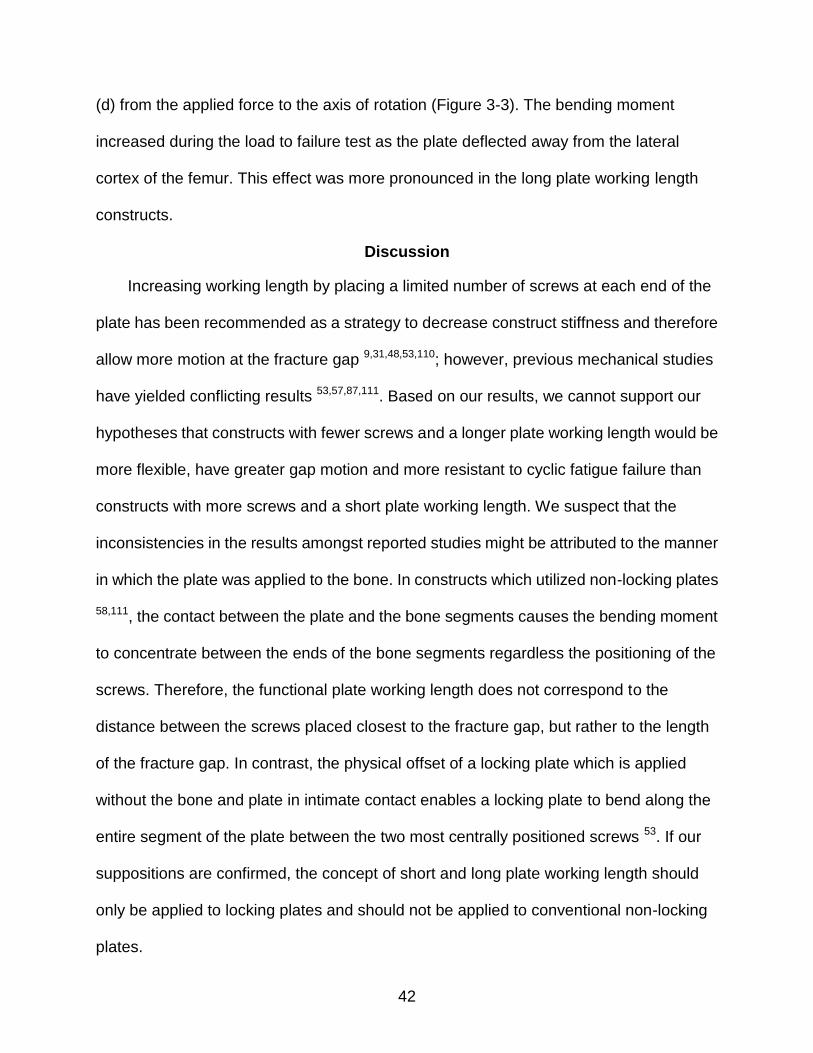
42
(d) from the applied force to the axis of rotation (Figure 3-3). The bending moment
increased during the load to failure test as the plate deflected away from the lateral
cortex of the femur. This effect was more pronounced in the long plate working length
constructs.
Discussion
Increasing working length by placing a limited number of screws at each end of the
plate has been recommended as a strategy to decrease construct stiffness and therefore
allow more motion at the fracture gap 9,31,48,53,110; however, previous mechanical studies
have yielded conflicting results 53,57,87,111. Based on our results, we cannot support our
hypotheses that constructs with fewer screws and a longer plate working length would be
more flexible, have greater gap motion and more resistant to cyclic fatigue failure than
constructs with more screws and a short plate working length. We suspect that the
inconsistencies in the results amongst reported studies might be attributed to the manner
in which the plate was applied to the bone. In constructs which utilized non-locking plates
58,111, the contact between the plate and the bone segments causes the bending moment
to concentrate between the ends of the bone segments regardless the positioning of the
screws. Therefore, the functional plate working length does not correspond to the
distance between the screws placed closest to the fracture gap, but rather to the length
of the fracture gap. In contrast, the physical offset of a locking plate which is applied
without the bone and plate in intimate contact enables a locking plate to bend along the
entire segment of the plate between the two most centrally positioned screws 53. If our
suppositions are confirmed, the concept of short and long plate working length should
only be applied to locking plates and should not be applied to conventional non-locking
plates.

43
The results of our cyclic fatigue testing are not consistent with previous studies
which found differences between constructs with short and long plate working lengths
53,111. These contrasting results might be ascribed to differences in the fracture models
employed and methods of loading. In our study the applied load was based on the dogs’
body weight in an attempt to replicate clinical situations. In other studies the upper load
threshold was set to induce implant failure within a predetermined number of cycles 85 or
was established using displacement control based on plate strain 87. Establishing
significance may have been masked in our study because we did not apply high enough
loads as none of our constructs failed during cyclic testing. The magnitude of the load
applied in diaphyseal fracture models is more complex than simply applying a load
equivalent to mean body weight. In human patients which have been instrumented with
distal femoral diaphyseal prosthesis with telemetric strain gauges, load values as high as
three times body weight and bending forces up to ten times body weight have been
recorded 125. Other loading protocols such as progressive loading 112 could have been
used to shorten the test protocol and may have yielded significant differences between
stabilization techniques.
Both the short and long plate working length stabilization constructs sustained
180,000 cycles with the equivalent of full body weight loaded in axial compression
without failure, which approximates 2 to 4 months of weight-bearing during normal
ambulation 126. This finding suggests that both constructs would likely provide acceptable
clinical stability as most fractures are expected to obtain union within 12 weeks of
stabilization 38,81. The yield load for both stabilization techniques ranged from 453 to 655
N, which corresponds to 2 to 4 times the hindlimbs peak vertical force measured from a

44
normal 20 kg dog running at a trot 15,127. Although kinetic values measured with gait
analysis are only an approximation of the forces tolerated by implants during loading, our
results suggest that it is unlikely that either of our constructs would fail catastrophically in
the early postoperative convalescent period.
Cadaveric studies have numerous limitations. When performing cyclic testing
designated to resemble a clinical environment after fracture fixation, the loading plane
should be considered 128. We selected an offset axial loading to simulate loading of a
plated femoral fracture. Our testing methodology had the limitation of being isolated to a
single plane, without considering more complex forces such as a combination of bending
and torsional forces. In the diaphyseal region of the femur, however, axial and bending
forces predominate and these forces were replicated in our testing protocol 125. Another
limitation was that we did not test a construct which exclusively utilized locking screws.
This omission limits our ability to make conclusions regarding the effect of working length
of a locking plate employed in its intended application 53,87. A hybrid construct in which
both locking and non-locking screws were used was selected because these constructs
are commonly used in dogs16. Furthermore, previous studies have shown that placement
of a single locking screw in each of the major fracture segments increases construct
stability subjected to axial and torsion loading 16,96,129,130.
We were unable to establish a significant effect of working length on stiffness and
resistance to cyclic fatigue in a fracture gap model plated with 2.4 mm LCP applied in
direct cortical contact with the femur. Our results question the advantage of long working
length in decreasing stiffness of the bone-plate construct and protecting the portion of
unsupported plate at the fracture gap 6,48,131. Neither of the constructs tested in our study

45
failed during cyclic load. Therefore both short and long working lengths constructs would
appear to be acceptable for clinical applications. Placing five bicortical screws in each of
the major fracture segments may not be necessary. Other studies have reported that
fewer, more widely spaced screws increased the bending strength of screw–plate
fixation more effectively than increasing the number of screws 31,55,131. Guidelines
regarding the optimal number of screws will, however, need to be derived from future
mechanical and clinical studies.

46
Figure 3-1. Constructs tested: long plate working length stabilization technique (left) and short plate working length stabilization technique (right). Each plate had a
2.4 mm locking screw (○) placed in the second hole from each end of the
plate. The other screws were 2.4 mm cortical screws (●).
Figure 3-2. Comparison of mean ± SD values of construct axial stiffness (N/mm) loaded to body weight between long plate working length stabilization
technique (□) and short plate working length stabilization technique(■).
Measurements recorded at 1000, 2000, 5000, 10000, 20000, 50000, 100000, 120000, and 180000 cycles. No significant difference was found between the two stabilization techniques at any of the evaluated cycles.

47
Figure 3-3. Photographs of a long and short plate working length construct before (left) and after (right) load to failure testing. The adjacent free body diagrams represent how bending moments were created. Bending moments (Force (F) x Distance (d)) were calculated based on measured scale distances obtained from photographs and the yield load of each construct.

48
CHAPTER 4 CONCLUSION
Plate working length is a major determinant of construct stiffness 53. A guideline of
whether to keep plate working length short or long remains controversial. The
recommendation of keeping at least two or three empty plate holes at the fracture site
were made in order to allow adequate construct flexibility when bridging a fracture 31,131.
Additionally it was theorized that two or three empty plate holes at the fracture site would
decrease plate strain at the fracture gap, therefore decreasing the risk of fatigue failure
9,131. However, several studies have demonstrated that a screw should be placed as
close to the fracture gap as possible in each major fracture segment, to decrease plate
strain and increase the resistance to fatigue failure53,57. Based on our testing results we
cannot support the hypotheses that constructs with longer plate working length
stabilization technique have lower stiffness, greater gap motion and are more resistant to
fatigue failure. No significant effect of working length were found on construct stiffness,
gap motion and resistance to cyclic fatigue in a fracture gap model plated with 2.4 mm
LCP applied in direct cortical contact with dog femur. Both short and long plate working
length stabilization techniques should be able to sustain through post-surgery coalescent
period in dogs.
Our results are inconsistent with previous studies in which they found that longer
plate working length stabilization technique has less stiffness, higher tensile strain and
earlier fatigue failure than short plate working length stabilization technique 53,57,111.
Inconsistent findings may results from different fracture model and loading methods. In
our study we fixed the plates flush on the femoral cortex which probably limited the
effective working length to the portion of the plate bridging the gap. In other words, the

49
working length may equal the size of fracture gap in a non-locking plate-bone construct.
Stoffel et al. applied plates at 2 mm offset from plate to bone, allowing plate bending over
the entire distance between two inner most screws on the plate. Therefore the plating
working length in a locking plate-bone construct truly corresponds to the distance
between the two innermost screws. Stoffel et al. focused on the contribution of the plate
to stiffness of the construct. This result results are similar to other studies that found no
significant difference of constructs stiffness and fatigue resistance between long and
short plate working length stabilization techniques 85,87. The mode of failure and plate
deformation observed in our study was consistent with Hoffmeier et al.’s study. In long
plate working length stabilization constructs, the free plate sections on both sides of the
gap bulged away from the bone during bending. Hoffmeier et al. found that the larger the
working length, the larger the radius of curvature would be and the evenly the stress
would be distributed. We might found the similar result of the stress distribution on the
plate because we have used similar femoral fracture model without leaving distance
between plate and bone as in Hoffmeier et al.’s study.
We applied LCP in hybrid fixation in which one locking screw was placed next to
other cortical screws in each bone segment. The effect of using locking screws in
combination with cortical non-locking screw in LCP applications is multifold: using
locking screws has been reported to increase axial strength and torsion resistance, as
well as increase the remaining torque in nearby cortical screws than all non-locking
screws fixation 16,129,130. Even though there is currently no study comparing the effect of
different plate working length on hybrid plate fixation, one study suggested that hybrid
plate fixation has similar bending strength and higher torsional strength than an

50
all-locked bridge plating construct in the osteoporotic diaphysis 97. Therefore, it is unlikely
that the hybrid plate fixation we used was the reason led to different results between our
study and other all-locked- screw study.
Cyclic loading is the mechanical test that more closely resembles the conditions of
fracture-healing in the clinical patient. However, it presents several limitations and
challenges. First, the loading plane should simulate the in vivo conditions that the implant
would experience in vivo. In our study we selected axial compression loading which
cause mainly bending force on the femur, because it is one of the most commonly force
that femurs encountered in physiological conditions 29,56. The magnitude of load is
another major factor that should be considered when designing a cycling test. To
simulate in vivo condition of loading, clinically relevant forces should be used. In people,
the physiological basis for testing loads is based on telemetrized implants such as
interlocking nails or total knee replacements, which directly measure the forces acting at
the level of the femoral diaphysis or at the knee joint, respectively. Because we lack of
these data for dogs, we chose testing loads based on dog’s body weight in an attempt to
replicate clinical situations 15.
The number of cycles required to test an implant for fracture fixation is controversial.
The presence of callus is a major factor in construct stability because it may develops as
early as 2 weeks following fracture fixation. Fracture callus protects the implant from
failure by providing load sharing, but cannot simulated in a laboratory setting. Our study
design is different than other studies in which fatigue tests were designed either the
upper load threshold was set to induce implant failure within a predetermined number of
cycles 85 or the number of cycles are as high as 1,000,000 cycles 17,53. Some other

51
studies used protocols as control displacement based on plate strain87 or applied
progressive loading 118, aimed at shortening the duration of cyclic fatigue test while also
assuring if significant differences between stabilization groups. Because all constructs
sustained through 180,000 cyclic weight-bearing loading in our study, the loads and the
number of cycles we chose were not high enough for constructs to reach fatigue failure.
Therefore, the significance may have been masked in our study.
The material of the plate is another factor affecting fatigue endurance of plate-screw
constructs. Hoffmeier et al compared the fatigue life between short, medium and long
working length in both stainless steel and grade-2 titanium 4.5 mm distal femoral plates
which bridged over a 10 mm fracture gap on a composite human femur 85. When plates
of different metals were compared, the stainless steel plates sustained higher cyclic load
than the grade 2-titanium plates. For the steel plates, no significant correlations were
found between fatigue strength and different working length groups. For the titanium
plates the fatigue strength was greater in constructs with long plate working length but
this correlation was not significant. Therefore, the effect of plate working length on
fatigue endurance may be greater in titanium plates than in stainless steel plates.
We did not evaluate other factors that affect plate-screw constructs stability such as
the number of screws inserted in each fragment. Studies which evaluated the effect of
different screw numbers on stiffness of plate-screw constructs reported that fewer, more
widely spaced screws increased the bending strength of screw–plate fixation more
effectively than increasing the number of screws 31,55,131. Other studies compared the
effect of different screw positions on plate strain or fatigue resistance 85,111. Therefore,
the effect of screw numbers should be minimal compared to the position of screws.

52
Future studies are necessary to evaluate if it is necessary to place screws in each screw
holes in the plate, especially considering the vascular trauma caused by drilling screw
holes in cortical bone 132.
Stoffel et al made the statement that as long as more than four screws were placed
each bone segment, the torsional rigidity would not be affected by the position of the
screws. Similar with other study suggested that regardless of the spacing of screws and
the plate length, strength in torsion was dependent on the number of screws securing the
plate 53,55. One study also reported that add a single locking screw to an otherwise
non-locking construct would increase the torsion rigidity 16. Therefore, if we tested our
constructs in torsion, the major variable that causes any difference should be the number
of screws rather than plate working length.
Longer plate working length stabilization technique has been shown to result in
higher plate strain in both experimental and computational study models 53,57,119,133. The
authors concluded that screws should be placed as closed to the fracture as possible in
order to decrease plate strain. However, one study evaluated the strain at and around
the fracture site in a gap model stabilized by 12-hole 3.5 mm LC-DCP and DCP, and
reported that the gap strain does not significantly change after screw removal 111. The
other study used a femoral fracture model and found a reduction of plate strain with
increasing plate working length stabilization technique 87. This finding is supported by a
computational simulation showing that a short plate working length produces stress
concentrations in the plate, which leads to fatigue failure 134. We did not measure plate
strain during test; however, we did not find any significant difference in gap motion during
cyclic testing. Based on our results, it is likely that we would not find any difference in gap

53
strain because gap strain is affected by gap motion. After load to failure test, both short
and long plate working length stabilization techniques have similar bending fulcrum at
the end of the proximal bone segment, which is likely the area where we would find the
greatest plate strain. However, the strain distribution along the entire plate between two
plate working length stabilization techniques during cyclic loading test would need further
testing to be determined.
Both short and long plate working length stabilization constructs should be
acceptable for clinical applications, because no construct failed during cyclic
weight-bearing loading. Based on our study design, no conclusion regarding clinical
guidelines can be provided and further mechanical and clinical studies are warranted.
Future study design should exclude the effect from different number of screws and the
application of both locking and non-locking screws in the plate.
When preparing a fracture stabilization plan, the choices will be different based on
different intention. If one would like to provide a fixation without traumatizing excessively
the surrounded soft tissue, a MIPO technique and a longer plate working length should
be acceptable based on our study result. However, if the higher strength of the fixation
construct is the goal, we would suggest placing screw as closed to the fracture gap as
possible in each of the major fracture segment. Future mechanical and clinical studies
are needed to establish guidelines regarding the optimal application of locking
compression plates.

54
LIST OF REFERENCES
1. Perren SM. Evolution of the internal fixation of long bone fractures. J Bone Joint Surg Am 2002;84:1093-1110.
2. Rozbruch RS, Müller U, Gautier E, et al. The evolution of femoral shaft plating technique. Clin Orthop 1998;354:195-208.
3. Miclau T, Martin RE. The evolution of modern plate osteosynthesis. Injury 1997;28, Supplement 1:A3-A6.
4. Egol KA, Kubiak EN, Fulkerson E, et al. Biomechanics of locked plates and screws. J Orthop Trauma 2004;18:488-493.
5. Smith WR, Ziran BH, Anglen JO. Locking plates: tips and tricks. Instr Course Lect 2008;57:25-36.
6. Smith WR, Ziran BH, Anglen JO, et al. Locking plates: tips and tricks. J Bone Joint Surg Am 2007;89:2298-2307.
7. Frigg R. Development of the locking compression plate. Injury 2003;34, Supplement 2:6-10.
8. Miller DL, Goswami T. A review of locking compression plate biomechanics and their advantages as internal fixators in fracture healing. Clin Biomech (Bristol, Avon) 2007;22:1049-1062.
9. Wagner M, Frigg R. AO manual of fracture management, internal fixators: concepts and cases using LCP and LISS. Clavadelerstrasse: AO Publishing, 2006.
10. Blake CA, Boudrieau RJ, Torrance BS, et al. Single cycle to failure in bending of three standard and five locking plates and plate constructs. Vet Comp Orthop Traumatol 2011:408-417.
11. Zahn K, Frei R, Wunderle D, et al. Mechanical properties of 18 different AO bone plates and the clamp-rod internal fixation system tested on a gap model construct. Vet Comp Orthop Traumatol 2008;21:185-194.
12. Aguila AZ, Manos JM, Orlansky AS, et al. In vitro biomechanical comparison of limited contact dynamic compression plate and locking compression plate. Vet Comp Orthop Traumatol 2005;18:220-226.
13. Filipowicz D, Lanz O, McLaughlin R, et al. A biomechanical comparison of 3.5 locking compression plate fixation to 3.5 limited contact dynamic compression plate fixation in a canine cadaveric distal humeral metaphyseal gap model. Vet Comp Orthop Traumatol 2009;22:270-277.

55
14. Gauthier CM, Conrad BP, Lewis DD, et al. In vitro comparison of stiffness of plate fixation of radii from large- and small-breed dogs. Am J Vet Res 2011;72:1112-1117.
15. Goh CSS, Santoni BG, Puttlitz CM, et al. Comparison of the mechanical behaviors of semicontoured, locking plate-rod fixation and anatomically contoured, conventional plate-rod fixation applied to experimentally induced gap fractures in canine femora. Am J Vet Res 2009;70:23-29.
16. Gordon S, Moens NMM, Runciman RJ, et al. The effect of the combination of locking screws and non-locking screws on the torsional properties of a locking-plate construct. Vet Comp Orthop Traumatol 2010;23:7-13.
17. Hammel SP, Elizabeth Pluhar G, Novo RE, et al. Fatigue analysis of plates used for fracture stabilization in small dogs and cats. Vet Surg 2006;35:573-578.
18. Hulse DON, Hyman W, Nori M, et al. Reduction in plate strain by addition of an intramedullary pin. Vet Surg 1997;26:451-459.
19. Johnston SA, Lancaster RL, Hubbard RP, et al. A biomechanical comparison of 7-hole 3.5 mm broad and 5-hole 4.5 mm narrow dynamic compression plates. Vet Surg 1991;20:235-239.
20. Leitner M, Pearce SG, Windolf M, et al. Comparison of locking and conventional screws for maintenance of tibial plateau positioning and biomechanical stability after locking tibial plateau leveling osteotomy plate fixation. Vet Surg 2008;37:357-365.
21. Silbernagel JT, Johnson AL, Pijanowski GJ, et al. A mechanical comparison of 4.5 mm narrow and 3.5 mm broad plating systems for stabilization of gapped fracture models. Vet Surg 2004;33:173-179.
22. Sod GA, Mitchell CF, Hubert JD, et al. In vitro biomechanical comparison of locking compression plate fixation and limited-contact dynamic compression plate fixation of osteotomized equine third metacarpal bones. Vet Surg 2008;37:283-288.
23. Sod GA, Riggs LM, Mitchell CF, et al. An in vitro biomechanical comparison of a 5.5 mm locking compression plate fixation with a 4.5 mm locking compression plate fixation of osteotomized equine third metacarpal bones. Vet Surg 2010;39:581-587.
24. Strom AM, Garcia TC, Jandrey K, et al. In vitro mechanical comparison of 2.0 and 2.4 limited-contact dynamic compression plates and 2.0 dynamic compression plates of different thicknesses. Vet Surg 2009;39:824-828.
25. Uhl JM, Seguin B, Kapatkin AS, et al. Mechanical comparison of 3.5 mm broad dynamic compression plate, broad limited-contact dynamic compression plate, and narrow locking compression plate systems using interfragmentary gap models. Vet Surg 2008;37:663-673.

56
26. DeTora M, Kraus K. Mechanical testing of 3.5 mm locking and non-locking bone plates. Vet Comp Orthop Traumatol 2008;21:318-322.
27. Cabassu JB, Kowaleski MP, Shorinko JK, et al. Single cycle to failure in torsion of three standard and five locking plate constructs. Vet Comp Orthop Traumatol 2011;24:418-425.
28. Terjesen T, Apalset K. The influence of different degrees of stiffness of fixation plates on experimental bone healing. J Orthop Res 1988;6:293-299.
29. Miclau T, Remiger A, Tepic S, et al. A mechanical comparison of the dynamic compression plate, limited contact-dynamic compression plate, and point contact fixator. J Orthop Trauma 1995;9:17-22.
30. Tan SLE, Balogh ZJ. Indications and limitations of locked plating. Injury 2009;40:683-691.
31. Gautier E, Sommer C. Guidelines for the clinical application of the LCP. Injury 2003;34:63-76.
32. Johnson AL, Smith CW, Schaeffer DJ. Fragment reconstruction and bone plate fixation versus bridging plate fixation for treating highly comminuted femoral fractures in dogs: 35 cases (1987-1997). J Am Vet Med Assoc 1998;213:1157-1161.
33. Johnson AL. Current concepts in fracture reduction. Vet Comp Orthop Traumatol 2003;16:59-66.
34. Chao P, Conrad B, Lewis D, et al. Effect of plate working length on plate stiffness and cyclic fatigue life in a cadaveric femoral gap model stabilized with a 12-hole 2.4 mm locking compression plate. Am J Vet Res 2012 Submitted.
35. Guiot LP, Déjardin LM. Prospective evaluation of minimally invasive plate osteosynthesis in 36 nonarticular tibial fractures in dogs and cats. Vet Surg;40:171-182.
36. Boero A, Peirone B. Comparison between minimally invasive plate osteosynthesis and open plating for tibial fractures in dogs Vet Comp Orthop Traumatol 2012, In press.
37. Palmer RH. Biological osteosynthesis. Vet Clin North Am Small Anim Pract 1999;29:1171-1185.
38. Claes L, Heitemeyer U, Krischak G, et al. Fixation technique influences osteogenesis of comminuted fractures. Clin Orthop Relat Res 1999:221-229.
39. Stoffel K, Klaue K, Perren SM. Functional load of plates in fracture fixation in vivo and its correlate in bone healing. Injury 2000;31, Supplement 2:37-86.

57
40. Claes LE, Heigele CA, Neidlinger-Wilke C, et al. Effects of mechanical factors on the fracture healing process. Clin Orthop 1998;355:S132-S147.
41. Claes L. Biomechanical principles and mechanobiologic aspects of flexible and locked plating. J Orthop Trauma 2011;25:S4-S7 10.1097/BOT.1090b1013e318207093e.
42. Tencer AF, Johnson KD. Biomechanics in orthopedic trauma: bone fracture and fixation. London: Martin Dunitz, 1994.
43. Taylor D. Fracture mechanics: how does bone break? Nat Mater 2003;2:133-134.
44. Perren SM. Physical and biological aspects of fracture healing with special reference to internal fixation. Clin Orthop 1975;138:175-194.
45. Cheal EJ, Mansmann KA, Digioia AM, et al. Role of interfragmentary strain in fracture healing: Ovine model of a healing osteotomy. J Orthop Res 1991;9:131-142.
46. Muir P, Johnson KA, Markel MD. Area moment of inertia for compression of implant cross-sectional geometry and bending stiffness. Vet Comp Orthop Traumatol 1995;8:146-152.
47. Reems MR, Beale BS, Hulse DA. Use of a plate-rod construct and principles of biological osteosynthesis for repair of diaphyseal fractures in dogs and cats: 47 cases (1994-2001). J Am Vet Med Assoc 2003;223:330-335.
48. Lill H, Hepp P, Korner J, et al. Proximal humeral fractures: how stiff should an implant be? Arch Orthop Trauma Surg 2003;123:74-81.
49. Oh J-K, Sahu D, Ahn Y-H, et al. Effect of fracture gap on stability of compression plate fixation: A finite element study. J Orthop Res 2010;28:462-467.
50. Bottlang M, Doornink J, Lujan TJ, et al. Effects of construct stiffness on healing of fractures stabilized with locking plates. J Bone Joint Surg Am 2010;92:12-22.
51. Snow M, Thompson G, Turner PG. A mechanical comparison of the locking compression plate (LCP) and the low contact-dynamic compression plate (DCP) in an osteoporotic bone model. J Orthop Trauma 2008;22:121-125.
52. Woo SLY, Lothringer KS, Akeson WH, et al. Less rigid internal fixation plates: Historical perspectives and new concepts. J Orthop Res 1983;1:431-449.
53. Stoffel K, Dieter U, Stachowiak G, et al. Biomechanical testing of the LCP - how can stability in locked internal fixators be controlled? Injury 2003;34:11-19.

58
54. Stoffel K, Lorenz K-U, Kuster MS. Biomechanical considerations in plate osteosynthesis: the effect of plate-to-bone compression with and without angular screw stability. J Orthop Trauma 2007;21:362-368.
55. Tornkvist H, Hearn TC, Schatzker J. The strength of plate fixation in relation to the number and spacing of bone screws. J Orthop Trauma 1996;10:204-208.
56. ElMaraghy AW, ElMaraghy MW, Nousiainen M, et al. Influence of the number of cortices on the stiffness of plate fixation of diaphyseal fractures. J Orthop Trauma 2001;15:186-191.
57. Ellis T, Bourgeault CA, Kyle RF. Screw position affects dynamic compression plate strain in an in vitro fracture model. J Orthop Trauma 2001;15:333-337.
58. Field JR, Tornkvist H, Hearn TC, et al. The influence of screw omission on construction stiffness and bone surface strain in the application of bone plates to cadaveric bone. Injury 1999;30:591-598.
59. Perren SM. The concept of interfragmentary strain. Berlin: Springer, 1980.
60. Jagodzinski M, Krettek C. Effect of mechanical stability on fracture healing ??an update. Injury 2007;38:S3-S10.
61. Augat P, Merk J, Wolf S, et al. Mechanical stimulation by external application of cyclic tensile strains does not effectively enhance bone healing. J Orthop Trauma 2001;15:54-60.
62. Claes L, Wolf S, Augat P. Mechanical modification of callus healing. Der Chirurg 2000;71:989-994.
63. Wolf S, Augat P, Eckert-Hübner K, et al. Effects of high-frequency, low-magnitude mechanical stimulus on bone healing. Clin Orthop Relat Res 2001;385:192-198.
64. Hente R, Füchtmeier B, Schlegel U, et al. The influence of cyclic compression and distraction on the healing of experimental tibial fractures. J Orthop Res 2004;22:709-715.
65. Goodship AE, Kenwright J. The influence of induced micromovement upon the healing of experimental tibial fractures. J Bone Joint Surg Br 1985;67-B:650-655.
66. Claes LE, Heigele CA. Magnitudes of local stress and strain along bony surfaces predict the course and type of fracture healing. J Biomech 1999;32:255-266.
67. Prendergast PJ, Huiskes R, Soballe K. Biophysical stimuli on cells during tissue differentiation at implant interfaces J Biomech 1997;30:539-548.
68. Blenman PR, Carter DR, Beaupré GS. Role of mechanical loading in the progressive ossification of a fracture callus. J Orthop Res 1989;7:398-407.

59
69. Carter DR, Beaupré GS, Giori NJ, et al. Mechanobiology of skeletal regeneration. Clin Orthop 1998;355:S41-S55.
70. Carter DR, Blenman PR, Beaupré GS. Correlations between mechanical stress history and tissue differentiation in initial fracture healing. J Orthop Res 1988;6:736-748.
71. Griffon D. Fracture healing: AO Publishing, 2005.
72. Isaksson H, Wilson W, van Donkelaar CC, et al. Comparison of biophysical stimuli for mechano-regulation of tissue differentiation during fracture healing. J Biomech 2006;39:1507-1516.
73. Carter DR. Mechanical loading history and skeletal biology. J Biomech 1987;20:1095-1109.
74. Kenwright J, Goodship AE. Controlled mechanical stimulation in the treatment of tibial fractures. Clin Orthop 1989;241:36-47.
75. Claes L, Grass R, Schmickal T, et al. Monitoring and healing analysis of 100 tibial shaft fractures. Langenbecks Arch Surg 2002;387:146-152.
76. Thomas PR, William MM. AO principles of fracture management. 2000.
77. Olerud S, Danckwardt-Lillieström G. Fracture healing in compression osteosynthesis. An experimental study in dogs with an avascular, diaphyseal, intermediate fragment. Acta Orthop Scand Suppl 1971;137:1-44.
78. Rahn BA, Gallinaro P, Baltensperger A, et al. Primary bone healing. An experimental study in the rabbit. J Bone Joint Surg Am 1971;53:783-786.
79. Schenk R, Willenegger H. On the histological picture of so-called primary bone healing of compression osteosynthesis in experimental osteotomies in the dog. Experientia 1963;19:593-595.
80. Goodship AE, Cunningham JL, Kenwright J. Strain rate and timing of stimulation in mechanical modulation of fracture healing. Clin Orthop 1998;355:S105-S115.
81. Baumgaertel F, Buhl M, Rahn BA. Fracture healing in biological plate osteosynthesis. Injury 1998;29:3-6.
82. Remedios A. Bone and bone healing. Vet Clin North Am Small Anim Pract 1999;29:1029-1044.
83. Klaushofer K, Peterlik M. Pathophysiology of fracture healing. Radiologe 1994;34:709-714.

60
84. Rhinelander FW. Tibial blood supply in relation to fracture healing. Clin Orthop 1974;105:34-81.
85. Hoffmeier KL, Hofmann GO, Mückley T. Choosing a proper working length can improve the lifespan of locked plates: A biomechanical study. Clin Biomech (Bristol, Avon) 2010;In Press, Corrected Proof.
86. Weiss DB, Kaar SG, P. FE, et al. Locked versus unlocked plating with respect to plate length in an ulna fracture model. Bull NYU Hosp Jt Dis 2008;66:5-8.
87. Kanchanomai C, Muanjan P, Phiphobmongkol V. Stiffness and endurance of a locking compression plate fixed on fractured femur. J Appl Biomech 2010;26:10-16.
88. Sanders R, Haidukewych GJ, Milne T, et al. Minimal versus maximal plate fixation techniques of the ulna: the biomechanical effect of number of screws and plate length. J Orthop Trauma 2002;16:166-171.
89. Fulkerson E, Egol KA, Kubiak EN, et al. Fixation of diaphyseal fractures with a segmental defect: a biomechanical comparison of locked and conventional plating techniques. J Trauma 2006;60:830-835
90. Perren S, Russenberger M, Steinemann SG. A dynamic compression plate Acta Orthop Scand Suppl 1969;125:31-41.
91. Perren SM, Mane K, Pohler O, et al. The limited contact dynamic compression plate (LC-DCP). Arch Orthop Trauma Surg 1990;109:304-310.
92. Th. Hopf SO. Interfragmental compression of the ZESPOL osteosynthesis system - an exploratory biomechanic experiment. Z Orthop Ihre Grenzgeb 1987;125:546-552.
93. Greiwe RM, Archdeacon MT. Locking plate technology: current concepts. J Knee Surg 2007;20:50-55.
94. Hasenboehler E, Rikli D, Babst R. Locking compression plate with minimally invasive plate osteosynthesis in diaphyseal and distal tibial fracture: a retrospective study of 32 patients. Injury 2007;38:365-370.
95. Khong K, Kotlanka R, Ghista DN. Mechanobiology in AO manual of fracture management. Minimally invasive plate osteosynthesis (MIPO). Stuttgart: Thieme Verlag, 2007.
96. Gardner MJ, Griffith MH, Demetrakopoulos D, et al. Hybrid locked plating of osteoporotic fractures of the humerus. J Bone Joint Surg 2006;88:1962-1967.
97. Doornink J, Fitzpatrick DC, Boldhaus S, et al. Effects of hybrid plating with locked and nonlocked screws on the strength of locked plating constructs in the osteoporotic diaphysis. J Trauma 2010;69:411-417.

61
98. Stoffel K, Booth G, Rohrl SM, et al. A comparison of conventional versus locking plates in intraarticular calcaneus fractures: A biomechanical study in human cadavers. Clinical biomechanics (Bristol, Avon) 2007;22:100-105.
99. Kim T, Ayturk UM, Haskell A, et al. Fixation of osteoporotic distal fibula fractures: a biomechanical comparison of locking versus conventional plates. J Foot Ankle Surg 2007;46:2-6.
100. Florin M, Arzdorf M, Linke B, et al. Assessment of stiffness and strength of 4 different implants available for equine fracture treatment: a study on a 20° oblique long-bone fracture model using a bone substitute. Vet Surg 2005;34:231-238.
101. Burkhart KJ, Mueller LP, Krezdorn D, et al. Stability of radial head and neck fractures: a biomechanical study of six fixation constructs with consideration of three locking plates. J Hand Surg Am 2007;32:1569-1575.
102. Siffri PC, Peindl RD, Coley ER, et al. Biomechanical analysis of blade plate versus locking plate fixation for a proximal humerus fracture: comparison using cadaveric and synthetic humeri. J Orthop Trauma 2006;20:547-554.
103. Boswell S, McIff TE, Trease CA, et al. Mechanical characteristics of locking and compression plate constructs applied dorsally to distal radius fractures. J Hand Surg Am 2007;32:623-629.
104. Weinstein DM, Bratton DR, Ciccone Ii WJ, et al. Locking plates improve torsional resistance in the stabilization of three-part proximal humeral fractures. J Shoulder Elbow Surg 2006;15:239-243.
105. Korner J, Diederichs G, Arzdorf M, et al. A biomechanical evaluation of methods of distal humerus fracture fixation using locking compression plates versus conventional reconstruction plates. J Orthop Trauma 2004;18:286-293.
106. O'Toole RV, Andersen RC, Vesnovsky O, et al. Are locking screws advantageous with plate fixation of humeral shaft fractures? A biomechanical analysis of synthetic and cadaveric bone. J Orthop Trauma 2008;22:709-715
107. Chiodo TA, Ziccardi VB, Janal M, et al. Failure strength of 2.0 locking versus 2.0 conventional synthes mandibular plates: a laboratory model. J Oral Maxillofac Surg 2006;64:1475-1479.
108. Amato NS, Richards A, Knight TA, et al. Ex vivo biomechanical comparison of the 2.4 mm UniLOCK® reconstruction plate using 2.4 mm locking versus standard screws for fixation of acetabular osteotomy in dogs. Vet Surg 2008;37:741-748.
109. Sommer C, Babst R, Müller M, et al. Locking compression plate loosening and plate breakage: a report of four cases. J Orthop Trauma 2004;18:571-577.

62
110. Kubiak EN, Fulkerson E, Strauss E, et al. The evolution of locked plates. J Bone Joint Surg Am 2006;88:189-200.
111. Maxwell M, Horstman CL, Crawford RL, et al. The effects of screw placement on plate strain in 3.5 mm dynamic compression plates and limited-contact dynamic compression plates. Vet Comp Orthop Traumatol 2009;22:125-131.
112. Bottlang M, Doornink J, Fitzpatrick DC, et al. Far cortical locking can reduce stiffness of locked plating constructs while retaining construct strength. J Bone Joint Surg Am 2009;91:1985-1994.
113. Bottlang M, Lesser M, Koerber J, et al. Far cortical locking can improve healing of fractures stabilized with locking plates. J Bone Joint Surg Am 2010;92:1652-1660.
114. Döbele S, Horn C, Eichhorn S, et al. The dynamic locking screw (DLS) can increase interfragmentary motion on the near cortex of locked plating constructs by reducing the axial stiffness. Langenbecks Arch Surg 2010;395:421-428.
115. Vallier H, Hennessey T, Sontich J. Failure of LCP condylar plate fixation in the distal part of the femur. A report of six cases. Journal of Bone and Joint Surgery (Am) 2006;88:846-853.
116. Lujan TJ, Henderson CE, Madey SM, et al. Locked plating of distal femur fractures leads to inconsistent and asymmetric callus formation. J Orthop Trauma 2010;24:156-162
117. Kregor PJ, Stannard JA, Zlowodzki M, et al. Treatment of distal femur fractures using the less invasive stabilization system: surgical experience and early clinical results in 103 fractures. J Orthop Trauma 2004;18:509-520.
118. Bottlang M, Doornink J, Byrd GD, et al. A nonlocking end screw can decrease fracture risk caused by locked plating in the osteoporotic diaphysis. J Bone Joint Surg Am 2009;91:620-627.
119. Korvick DL, Monville JD, Pijanowski GJ, et al. The effects of screw removal on bone strain in an idealized plated bone model. Vet Surg 1988;17:111-116.
120. Kanchanomai C, Phiphobmongkol V, Muanjan P. Fatigue failure of an orthopedic implant - A locking compression plate. Eng Fail Anal 2008;15:521-530.
121. Koch D. Screws and plates In: Johnson AL, Houlton JEF,Vannini R, eds. AO principles of fracture management in the dog and cat. New York: Thieme, 2005;27-51.
122. Synthes® website. Mini fragment system. Instruments and implants for 1.5 mm, 2.0 mm and 2.4 mm plates, 2008.

63
123. Crane III CD, Duffy J. Kinematic analysis of robot manipulators: Cambridge University Press, 2008.
124. Hvid I, Jensen J. Cancellous bone strength at the proximal human tibia. Eng Med 1984;13:21-25.
125. Taylor SJG, Walker PS. Forces and moments telemetered from two distal femoral replacements during various activities. J Biomech 2001;34:839-848.
126. Aper RL, Litsky AS, Roe SC, et al. Effect of bone diameter and eccentric loading on fatigue life of cortical screws used with interlocking nails. Am J Vet Res 2003;64:569-573.
127. Bertram JEA, Lee DV, Case HN, et al. Comparison of the trotting gaits of Labrador Retrievers and Greyhounds. Am J Vet Res 2000;61:832-838.
128. Gardner MJ, Silva MJ, Krieg JC. Biomechanical testing of fracture fixation constructs: variability, validity, and clinical applicability. J Am Acad Orthop Surg 2012;20:86-93.
129. Goswami T, Patel V, Dalstrom DJ, et al. Mechanical evaluation of fourth-generation composite femur hybrid locking plate constructs. J Mater Sci Mater Med 2011;22:2139-2146.
130. Freeman AL, Tornetta P, III, Schmidt A, et al. How much do locked screws add to the fixation of "hybrid" plate constructs in osteoporotic bone? J Orthop Trauma 2010;24:163-169
131. Wagner M. General principles for the clinical use of the LCP. Injury 2003;34:31-42.
132. Field JR, Sumner-Smith G. Bone blood flow response to surgical trauma. Injury 2002;33:447-451.
133. Izaham RMAR, Kadir MRA, Muslim DAJ. Screws placement effect on locking compression plate (LCP) for tibial oblique fracture fixation. Biomedical Engineering and Sciences (IECBES), IEEE EMBS Conference 2010;236-241.
134. Chen G, Schmutz B, Wullschleger M, et al. Computational investigations of mechanical failures of internal plate fixation. Proc Inst Mech Eng H 2010;224:119-126.

64
BIOGRAPHICAL SKETCH
Peini Chao grew up in Taipei, Taiwan with her family. She graduated from Taipei
First Girl High School in 2003. She studied in the college of Veterinary Medicine in
National Taiwan University. After one-year rotational internship training in Animal
Hospital of National Taiwan University, she earned her D.V.M. in National Taiwan
University in 2009. During the summer in 2007, she completed an externship in Elwood
Animal Clinics in California.
Upon graduating in August 2009 with her D.V.M., Peini enrolled the Master of
Science program in Department of Small Animal Clinical Science in College of
Veterinary Medicine in University of Florida. She works in Comparative Orthopedic
Biomechanics laboratory, research strengthens on mechanical evaluation of plate-screw
constructs. She earned her M.S. in summer 2012.
After completion of her M.S. program, Peini will be back to Taipei, Taiwan,
continuing work in small animal practice.