MECHANICAL ENGINEERING DEPARTMENT BUREAU OF INDIAN …1423-1424)_05022015.pdf · ·...
33
MECHANICAL ENGINEERING DEPARTMENT BUREAU OF INDIAN STANDARDS Refrigeration and Air Conditioning Sectional Committee, ME 03 To: a) The interested members of Mechanical Engineering Division Council, MEDC; b) All members of Refrigeration and Air Conditioning Sectional Committee, ME 03; c) All others interested. Dear Sir (s), Please find enclosed the following documents: Doc. No. TITLE Prepared by 1. Doc: MED 03(1424)P Specification for Thermostatic Expansion Valves (First Revision of IS 10594 : 1983) Shri Deepak Verma, M/s Danfoss Industries Pvt. Ltd., New Delhi 2. Doc: MED 03(1423)P Specification For Bottle Coolers (First Revision of IS 2167 : 1983) Shri Ritesh Singh, M/s Voltas, Pant Nagar Kindly examine the Draft Standards and forward your views stating any difficulties which you are likely to experience in your business or profession, if this is finally adopted. Last date for receipt of comments: March 31, 2015. Comments, if any, may please be made in the format as attached and e-mailed to the undersigned at the above address. In case no comments are received or comments received are of editorial nature, you will kindly permit us to presume your approval for the above document as finalized. However, in case of comments of technical in nature are received then it may be finalized either in consultation with the Chairman, Sectional Committee or referred to the Sectional committee for further necessary action if so desired by the Chairman, Sectional Committee. The document is also hosted on BIS website www.bis.org.in. Thanking you, Yours faithfully (A.K. Mohindroo) Scientist ‘B (Mech Engg) Phone/Fax: 011-23232509 E-mail: [email protected] Encl: As above NOTE-WHERE PRINCIPAL AND ALTERNATE MEMBERS OF AN ORGANISATION ARE FROM THE SAME STATION, ONE COPY OF THE DOCUMENT IS SENT ONLY TO THE PRINCIPAL MEMBER WHO MAY KINDLY SHARE THIS WITH HIS ALTERNATE AS WELL. Copy to - 1. Chairman, ME 03 for kind information please. 2. ITS for hoisting it on the BIS Website. DRAFT STANDARD IN PROPOSED DOCUMENT DESPATCH ADVICE Ref: ME 03/T-23&10 Date: 04-02-2015
Transcript of MECHANICAL ENGINEERING DEPARTMENT BUREAU OF INDIAN …1423-1424)_05022015.pdf · ·...
MECHANICAL ENGINEERING DEPARTMENT
BUREAU OF INDIAN STANDARDS
Refrigeration and Air Conditioning Sectional Committee, ME 03
To: a) The interested members of Mechanical Engineering Division Council, MEDC; b) All members of Refrigeration and Air Conditioning Sectional Committee, ME 03; c) All others interested. Dear Sir (s), Please find enclosed the following documents:
Doc. No. TITLE Prepared by
1. Doc: MED 03(1424)P Specification for Thermostatic Expansion Valves (First Revision of IS 10594 : 1983)
Shri Deepak Verma, M/s Danfoss
Industries Pvt. Ltd., New Delhi
2. Doc: MED 03(1423)P Specification For Bottle Coolers (First Revision of IS 2167 : 1983)
Shri Ritesh Singh, M/s Voltas, Pant Nagar
Kindly examine the Draft Standards and forward your views stating any difficulties which you are likely to
experience in your business or profession, if this is finally adopted. Last date for receipt of comments: March 31, 2015. Comments, if any, may please be made in the format as attached and e-mailed to the undersigned at the above address. In case no comments are received or comments received are of editorial nature, you will kindly permit us to
presume your approval for the above document as finalized. However, in case of comments of technical in nature
are received then it may be finalized either in consultation with the Chairman, Sectional Committee or referred to
the Sectional committee for further necessary action if so desired by the Chairman, Sectional Committee.
The document is also hosted on BIS website www.bis.org.in. Thanking you, Yours faithfully (A.K. Mohindroo) Scientist ‘B (Mech Engg) Phone/Fax: 011-23232509 E-mail: [email protected] Encl: As above NOTE-WHERE PRINCIPAL AND ALTERNATE MEMBERS OF AN ORGANISATION ARE FROM THE SAME STATION, ONE COPY OF THE DOCUMENT IS
SENT ONLY TO THE PRINCIPAL MEMBER WHO MAY KINDLY SHARE THIS WITH HIS ALTERNATE AS WELL.
Copy to -
1. Chairman, ME 03 for kind information please.
2. ITS for hoisting it on the BIS Website.
DRAFT STANDARD IN PROPOSED
DOCUMENT DESPATCH ADVICE Ref: ME 03/T-23&10 Date: 04-02-2015

1
IS 2167 : 1983 Doc. No. MED 03 (1423) P
For BIS Use Only
Proposed Draft Standard SPECIFICATION FOR BOTTLE COOLERS
( First Revision of IS 2167 : 1983)
Draft prepared by Shri Ritesh Singh, Last date for receipt of
M/s Voltas, Pant Nagar comments is March 31, 2015 1 SCOPE Prescribes the general constructional requirements and methods of testing and rating dry type self-contained bottle coolers operated by electrically driven vapour compression type refrigerating machine with air-cooled condenser. 2 REFERENCES
The following Standards contain provisions which through reference in this text, constitute provisions of
the standards. At the time of publication, the editions indicated were valid. All standards are subject to
revision and parties to agreements based on this standard are encouraged to investigate the possibility of
applying the most recent editions of the Standards indicated below:
IS Number Title
IS 9968 : 1988 Elastomer Cables : Part 1 - For working voltages upto and including
1 100 V (First Revision)
IS : 694-2010 Polyvinyl Chloride Insulated Unsheathed--And Sheathed Cables/cords
With Rigid And--Flexible Conductor For Rated Voltages--Up To And
Including 450/750 V (Fourth Revision)
IS : 732-1989 Code of practice for electrical wire installations (Third Revision)
IS: 11338:1985 Thermostats for Use in Refrigerators, Air Conditioners, Water Coolers
and Beverage Coolers
IS : 996-2009 Single-phase a.c. industrial motors for general purpose (third revision)
IS 302 - I : 2008 Safety of household and similar electrical appliances Part 1 - General
requirements (Sixth revision).
3 TERMINOLOGY
For the purpose of this standard, the following definitions shall apply. 2.1 Bottle Cooler
2
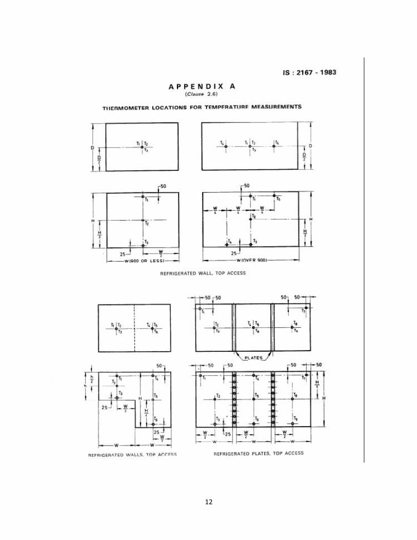
A machine to cool and dispense bottled drinks. 2.2 Bottle Opener A device fixed at a convenient place to the bottle cooler for purposes of moving the caps of bottles. 2.3 Dispenser A suitable arrangement to hold fresh or empty bottles for the ready use of the vendor or customer. 2.4 Dry Type Self-Contained Bottle Cooler Medium in the refrigerated storage space. One which uses air, rather than water, as the cooling. 2.5 Vapour Compression cycle A refrigeration cycle in which a volatile liquid absorbs heat, evaporates and is compressed to a higher pressure and temperature to return to its liquid state again, by surrendering heat at a higher temperature and Pressure. 2.6 The Average Cabinet Air Temperatures The average air temperature taken by means of the thermocouples or thermometers located at Places in the cabinet as shown in Appendix A at any, point of the thermostatic cycle. 2.7 Cycles per 24 Hours A Cycle in the Operation Of a bottle cooler is the period during which a compressor goes through the steps of starting, running, Stopping and Starting again. Cycles per day can be determined by dividing the number of Complete Cycles by the elapsed time in hours and multiplying the result by 24. 2.8 Percentage Running Time The Percentage running time, under given conditions of ambient ternperatures and of mean internal temperature, is the ratio:
R = x 100
where
d = duration of compressor operation during a full number of cycles, and D = total duration of the Cycles.
2.9 Overall Dimensions Measurement of the outside rectangular dimensions over the horizontal base within which the bottle cooler including the accessories other than bottle opener and handle arc inscribed.
2.10 Gross Volume Total volume contained within interior walls of the cabinet with the door closed and determined by the method given in 4.3. 2.11 Storage Volume
3
The total volume contained inside the cabinet for storage of bottles. This will be equal to the gross volume minus volume of internal fittings as described in 4.4. 2.12 Bottle Storage Capacity The total number of standard 190 ml beverage bottles that car be loaded inside the cabinet. In addition, this may also be expressed in terms of number of standard 650 ml beer bottles. 3 CONSTRUCTION 3.1 General Design The cabinet and their parts shall be constructed with strength and rigidity adequate to withstand normal conditions of handling, transport and usage. Where an internal light is fitted, the lamp shall be effectively protected from mechanical damage but shall be accessible without excessive dismantling. There shall be no sharp edges or corners liable to cause injury to the user in the normal conditions of use. 3.2 Materials Materials used in the construction of the cabinet shall comply with Indian Standards wherever applicable, except where such requirements are modified by this standard. They shall be free from defects which are liable to cause undue deterioration or failure. Under normal conditions of use, the materials used shall not shrink, warp or cause odour and shall be resistant to attach by local vermins and destructive pests. Sealing materials used shall not become lose in service any of their essential properties, such as adhesiveness, plasticity and moisture resistance, due to ageing, temperature and humidity variations. 3.3 Finish The interior and exterior finish shall be durable and capable of being cleared effectively and hygienically without undue deterioration. All metal parts used inside or outside the cooler which are exposed to moisture or ambient conditions shall be corrosion resistant or adequately protected against corrosion. 3.4 Thermal Insulation The quality, thickness and application of the insulating material shall be such as to maintain the required temperature inside the cabinet. There shall be proper seals against moisture penetration by diffusion or condensation. Detachable plates and covers in the cabinet shall be provided with suitable seals to prevent ingress of moisture into the insulation. External surfaces of the cabinet shall be free from moisture condensation under normal conditions of service. 3.5 Fittings Linings and facing shall have sufficient mechanical strength to resist distortion and give reasonable protection to the insulation. When the lids of the refrigerated space are closed, there shall be no leakage of external air into the cabinet either past the lid gaskets or by any other means. 3.6 Hardware Lid fasteners and hinges shall be smooth and positive in action and designed to maintain their proper function without undue wear under normal conditions of service. Screws and all other hardware shall be of corrosion resisting material. 3.7 Refrigeration System 3.7.1 Construction -The pipes and connections to moving or resiliently mounted parts shall be arranged so as not to foul with or transmit vibration to other parts. The pipes and connections shall be securely

4
fixed and should be of sufficient length to minimize the risk of failure due to vibration. The refrigerating system shall not have distinct nuisance noise in the normal running operation and should not transmit vibration to adjoining portions of the surroundings. Where necessary pipes and valves shall be properly insulated. 3.7.2 Safety features in design - The refrigerating system shall be assembled in accordance with good engineering practice. The refrigerating system shall be so designed that it will suffer no damage if the lid of the cabinet is left open accidently for a short duration in ambient air of the specified temperature. During this period motor overload protective device may come into operation. 3.7.3 Control of operations - Refrigerant flow and compressor motors shall be automatically controlled to reduce the cabinet temperature to the temperature specified and to maintain it within the limits of applications. Suitable strainer shall always be provided in the liquid line. 3.7.4 Location of components - The evaporator, screen and shelves shall not obstruct access to the stored bottles. All control devices and service valves shall be readily accessible. 3.7.5 Strength of pressure parts - The parts of the refrigerating circuit subjected to internal pressure shall be perfectly tight. They should be designed to withstand without permanent deformation and leakage the pressure given in Table I. 3 ELECTRICAL COMPONENTS 3.8.1 All ratings shall be based on either 230 or 240 volts in the case of single phase supply and either 400 or 415 volts in the case of 3 phase supply. The unit, however, shall be capable of working at any voltage within ±10 percent of the rated voltage.
TABLE 1 TEST PRESSURE ( Clause 3.7.5 )
Refrigerant Pressure (Gauge)
R-134a F3CCH2F 20 bar
R-404a CHF2CF3,CH3CF3,CH2FCF3 30 bar
R-12 should be removed as it has been banned under Montreal protocol.
For companies using natural refrigerants like hydrocarbons adequate care should be taken to confine the
charge quantity below lower flammability limit.
Note - When a system is such that its low side pressure cannot by reasons of its design, go beyond a maximum pressure of Pm, the test pressure shall be Pm x 13 provided such pressure does not exceed that shown in table.
3.8.2 Electric motors - Electric motors for hermetically sealed compressors shall be so constructed that the constant pressure of oil and refrigerant under working pressure and temperature has no adverse effect on the insulation material and windings. 3.8.3 Compressor motor overload protector - The compressor motor shall be connected through a current and temperature sensitive protecting device which is capable of automatically disconnecting the motor from the line. in case the motor is electrically or thermally overloaded either during starting or running.
5
3.8.4 Electrical contacts - Electrical contacts in relays and thermostats should be of snap action type and shall he of ample capacity to easily handle the locked rotor current, that is, the continuous current taken by the motor when its rotor is mechanically locked so as to prevent its rotation. 3.8.5 Flexible cord- Three-core cable conforming to IS : 9968 ( Part 1) - I988 ─ Elastomer Cables : Part 1
- For working voltages upto and including 1 100 V or IS : 694-2010- Polyvinyl Chloride Insulated
Unsheathed--And Sheathed Cables/cords With Rigid And--Flexible Conductor For Rated Voltages--Up To
And Including 450/750 V’ of at least 1.5 metres length shall be provided with each unit. A three-pin plug
and starter, if required, shall be provided at the time of installation.
3.8.6 Wiring- Electrical wiring and connections shall conform to the requirement of IS : 732-1989 ‘Code of Practice for Electrical Wiring Installations (third revision) and also to the Indian Electricity Act, 1910 and Indian Electricity Rules 1956. All electrical joints shall be electrically and mechanically secure. 3.8.7 Accidental contact- Live parts shall be protected by suitable guards, shields or screens of adequate strength and durability to avoid the possibility of making inadvertent contact therewith during normal service conditions. 3.8.8 Electrical accessories - All internal electrical fittings, such as lamps, and switches, shall be provided with guards for protection against mechanical damage and shall be suitable for operation at the lowest air temperature likely to occur. 3.8.9 Terminals-The materials, design and proportions of all terminals shall be such that connections
made shall not slacken or overheat under the normal conditions of use. Terminals shall be such that
conductors connected thereto are rigidly and effectively clamped between metal surfaces. Terminal
screws and nuts shall engage for at least two full turns.
3.8.10 Thermostat- The thermostat should conform to IS: 11338:1985 ─ Thermostats for Use in
Refrigerators, Air Conditioners, Water Coolers and Beverage Coolers
3.8.11 Provision for Earthing- The cabinet shall be provided with a suitable terminal for attaching the earth
conductor and this terminal shall be in effective electrical contact with accessible metal parts during
normal use or when any cover or casing, removable without the use of tools, has been removed and
which is liable to become live in the case of breakdown of electrical insulation.
The earth terminal shall be so designed that the pressure necessary to clamp the conductor shall not
serve to secure any other component. The terminal shall be clearly and indelibly indicated by the letter ‘E’
and the symbol L or by green or green/yellow colour and the symbol
4 MEASUREMENT OF BOTTLE COOLER STORAGE CAPACITY 4.1 Accuracy of Measurement and Units Linear dimensions shall be measured to the nearest millimeter. Areas estimated shall be expressed in square decimeters. Volumes estimated shall be expressed in cubic decimeters or litres. 4.2 Inside Dimensions of the Cabinet
6
4.2.1 Front access type 4.2.1.I Inside depth -This shall be the mean horizontal distance between the front and the rear inside surface of the enclosed space of the cabinet. 4.2.1.2 inside width - This shall be the mean horizontal distance between the inner surfaces of the side walls of the enclosed space. 4.2.1.3 Inside height - This shall be mean vertical distance between the inner surfaces of the floor and the ceiling of the enclosed space. 4.2.2 Top access type 4.2.2.1 Inside depth ─This shall be the mean horizontal distance between the front and rear inner surfaces of the front and back walls of the enclosed space of the cabinet. 4.2.2.2 inside width ─ This shall be the mean horizontal distance between the inner surface of the side walls of the enclosed space. 4.2.2.3 Inside height ─This shall be the mean vertical distance between the inner surface of the floor and the lids. 4.3 Gross Volume The gross volume of the bottle cooler shall be the product of inside depth, inside width and inside height as defined in 4.2.1 and 4.2.2. 4.4 Storage Volume ( Net Volume) The storage volume shall be the gross volume or sum of the gross volumes of individual compartments less the volumes of internal fittings fixed in the cabinet and the volumes of the shelves and partitions essential for the proper operation of the cabinet, provided each part is more than 0.25 litre. 4.5 Volume of Shelves, Partitions and Internal Fittings The volume of a shelf, partition or internal fitting shall be the product of its area and thickness. The area of a shelf shall be the product of its width and depth. Where part of the shelf is cut away, the area of the cut-out shelf shall be deducted. Where the edge of the shelf is not more than 25 mm from the cabinet lining, the shell shall be considered as extending to the lining for the purpose of calculating shelf area. Where there is an access door in a wall of the cabinet the inner surface of the door shall be considered as being the inner surface of the lining. 4.5.1 The thickness of the shelves and partitions shall be the distance between the outer surface excluding the edges, where those are reinforced (see Fig. 1). Where surfaces are corrugated or fitted with pipe grids, the plane through the apices of the corrugations or pipes shall be used for calculating volumes except that where the door distance between adjacent corrugations or pipes is greater than 100 mm the surface itself shall be used and a volume shall be deducted for each corrugation or pipe equal to the product of the width, the distance from the surface to the outside of the corrugation or pipe and the length of the corrugation of pipe.
7
4.6 Full Partitions The volume of a full partition is the product of its thickness, depth and width or height. This depth, width and height are those dimensions of the cabinet applicable in the Place of partition. 4.7 Fractional Partitions The volume of a permanently fixed fractional partition is the /product of it thickness, depth and width or height whichever of these two is applicable. The depth, width or height are the distances normal to the lining from adjacent surfaces to the further edges of, the partitions or to the evaporator in case the fractional partition touches it. A horizontal partition the edges of which are more than 70 mm from the lining of the cabinet is regarded as fractional partition. A vertical partition, the edges of which are more than 100 mm from the lining of the cabinet, is regarded as a fractional partition. 4.8 Rated Gross Volume This shall be the gross volume as declared by the manufacturer in cubic decimeters or litres. The measured gross volume as described in 4.3 shall not be less than the rated gross volume by more than 5 percent. 4.9 Rated Storage Volume This shall be the storage volume as declared by the manufacturer in cubic decimeters or litres. The measure storage (net) volume as described in 4.4 shall not be less than the rated storage volume by more than 5 percent. 4.10 Rated Bottle Storage Capacity This shall be the storage capacity as declared by the manufacturer in terms of number of standard 190 ml beverage’ bottles. In addition storage capacity in terms of number of standard 650 ml bottles may also be declared by the manufacturer. The actual bottle storage capacity shall not be less than rated bottle storage capacity by more than 5 percent. 5 Tests 5.1 Type Tests The following shall constitute the type test:
a) Thermal insulation test, b) Insulation resistance test, c) High voltage test, d) No load performance test, e) Percentage running time test, f) Capacity rating test, and g) Maximum operating condition test.
5.1.7 Once a bottle cooler has undergone type test any major .alterations affecting the performance which the manufacturer intends to make in the bottle cooler shall be reported to the testing authority recommended by ISI and further type test shall be carried out in the modified bottle cooler in ‘accordance with the procedure laid down in this standard (see 5.7). 5.2 Production Routine Tests
8
Every bottle coolers, after completion shall be subjected to the following routine tests: a) Insulation resistance test; b) Performance test, and c) High voltage test 5.2.1 The manufacturer shall furnish with each bottle cooler a certificate that the production routine tests specified in 5.2 have been conducted in accordance with the prescribed procedure (see 5.8) and that the unit conforms to the requirement of this standard. 5.3 Acceptance Tests If the purchaser desires any of the production routine tests to be repeated at the time of purchase then, where agreed to between the purchaser and the manufacturer, the tests shall be carried out at the manufacturer’s works, alternatively, the test may be repeated at a place specified by the purchaser provided all the arrangements for tests are made by the purchaser at the specified place. 5.4 Sample for Tests 5.4.1 Type tests ─ Two bottle coolers of each type and size shall be sent along with manufacturer’s detailed specifications to the appropriate testing authority for purposes of type tests. Type tests can be performed by the manufacturer himself if approved by the purchaser. 5.4.2 Acceptance tests ─ The number of samples shall-be as agreed to between the purchaser and the manufacturer. 5.5 Preparation and Test Conditions for Type Tests 5.5.1 Each specimen tested shall be selected from stock or routine factory production, and shall be representative of construction and adjustments. 5.5.2 The bottle cooler with all panels and lids in place, shall be tested in a room in which the temperature can be controlled. Panels and lids should remain in place throughout the entire test. 5.5.3 Bottle coolers shall be operated until stable operating conditions are reached. The stable conditions are deemed to have reached when during a time of 2 hours the average cabinet air temperature does not vary by more than 0.5°C. 5.5.4 The bottle cooler being tested shall be located in a room so that its temperature is not affected by direct radiation to or from external cooling or heating equipment. The air circulation in the room shall be such that the specified uniformity of ambient temperature is obtained without direct draft upon the bottle cooler under test. 5.5.5 The fan motor and compressor shall be SO connected as to facilitate measurement of the power
input. When tested under actual working conditions the fan motor should conform to the requirements
specified in IS 996 : 2009─Single Phase A.C. Induction Motors For General Purpose-(Third Revision).
5.5.6 For the test during which the bottle cooler will be in operation, electric power supply shall not vary by more than ±2 percent of the rated voltage. 5.5.7 Bottles shall be filled with either beverage liquid or water. Alternatively suitable brine solution may be used if there is any likelihood of temperature falling to 0°C or less. 5.5.8 Bottle temperature shall be measured by thermocouple located approximately at the centre of the mass of the liquid in the bottle. Bottles shall be corked with provision for bringing the thermocouple leads out through the cork.

9
5.5.9 For determination of average bottle temperature, liquid temperature should be measured in bottles located at uniformly distributed points inside the cabinet, including measurement in top layers and .one measurement in the bottom layer of bottles. Apart from these two locations, additional bottles should be based on approximately one bottle per 100 to 150 litres of storage volume, 5.6 Instruments 5.6.1 Temperature measurements shall be made with one or more of the following instruments:
a) Mercury-in-glass thermometer, b) Alcohol-in-glass thermometer, c) Thermocouples, d) Electric resistance thermometers, or e) Electric resistance measurements instruments having accuracy 0.2 percent of the scale.
5.6.1.I Accuracy of measurement shall be within ± 0.5ºC. 5.6.2 Electrical measurements shall be made with indicating instruments. 5.6.2.1 The accuracy of indicating instruments Shall be within 1.5 Percent of the full scale reading. 5.6.3 The Smallest division on the scale of any instrument shall not exceed twice the specified accuracy for it. 5.7 Procedure for Type Tests 5.7.1 Thermal insulation test (external condensation test) ─The bottle cooler cabinet shall be held with an average internal temperature between 4°C to 8°C under ambient temperature of 32 ± 2°C. ft Shall be considered satisfactory if. when the relative humidity of the ambient air is held between 70 to 75 percent condensed moisture is not visible on the Outer surface of the bottle cooler to the unaided eye of a trained observer during a period of time lasting for 12 hours after the test conditions have become stable. 5.7.2 insulation resistance test ─ The insulation resistance between all electric circuits included in the bottle coolers, and earthed metal parts, when measured at normal room temperatures with a voltage of 500 V dc, shall not be less than 1 MQ at the end Of the maximum operating condition test. This test Should be repeated after high voltage test. 5.7.3 High voltage test ─ The electrical insulation of all electric circuits included in the bottle cooler shall be such as to withstand a high voltage test of 1 000 V rms applied for 2 seconds between aft electric circuits and all accessible metal parts (electrically connected together for this test) at normal room temperature. The test voltage shall be alternating, of approximately sine-wave form, and of any convenient frequency between 25 to 100 Hz. 5.7.4 No-load performance test ─ With the bottle cooler working under no-load and with the thermostat terminals short-circuited, at ambient temperature of 35 ± 2°C, the time required to pull down the average cabinet air temperature from 35 ± 2°C to 4°C shall not exceed 3 hours. 5.7.5 Power consumption test and Percentage running test ─ For this test, the cabinet shall be tested on
no-load, with lids closed and the thermostat set for maximum cooling. The duration of the test will be 12
hours at an ambient temperature of 35 ± 2 °C. Power Consumption and Percentage running time will be
taken as average of three successive runs in the later half of this period. It should not exceed the value
stated by the manufacturer by more than 5 percent.

10
5.7.6 Capacity rating test ─This test should immediately follow percentage running time without switching off the unit. In case, this is not possible then the unit should run on no-load for a minimum period of 3 hours under prevailing ambient conditions before the start of this test. During the entire test period, the ambient temperature should be maintained at 35 ± 2°C and thermostat should be set for maximum cooling. Unit should be loaded with specified number of standard 190 ml bottles at an initial temperature of 30 ± 2°C. Rate of loading of bottles should not be less than 10 bottles per minute. Once the loading is over, lids should be properly closed. The test duration starts from the moment the lids are closed. Bottle temperatures should be recorded every 30 minutes for specified pull down period which shall not exceed 12 hours. Average temperature of bottles at the end of specified pull down period shall not be greater than 5°C, and the maximum bottle temperature shall not exceed 8°C. 5.7.7 Maximum operating conditions test ─ This test should immediately follow capacity rating test without switching off the unit. In case this is not possible the unit should run on no-load for a minimum of3 hours under prevailing ambient conditions before the start of this test. During the entire test period the ambient temperature should be maintained at 43 ± 2°C and the thermostat should be set for maximum cooling. Unit should be loaded with specified number of standard 190 ml bottles at an initial temperature of 35 ± 2 ºC. Rate of loading of bottles should not be less than 10 bottles per minute. Once the loading is over, lids should be properly closed. The test duration starts from the moment the lids are closed. Bottle temperatures should be recorded every 30 minutes for specified pull down period which shall not exceed 18 hours. Average temperature of bottles at the end of specified pull down period shall not be greater than 5°C and the minimum bottle temperature shall not exceed 8°C. NOTE ─ Unit may trip on overload protector during initial stage of the test. This should be considered as permissible.
5.7.8 The type test report shall also contain the following identification data: a) Name-plate data of bottle cooler, b) Name-plate data of compressor, and c) Name-plate data of fan motor. 5.8 Procedure for Production Routine Tests 5.8.1 Insulation resistance test ─- Electrical insulation test shall be carried out at 500 V dc, given in 5.7.2 at the end of performance test. 5.8.2 Performance test ─This test should be carried out with thermostat short-circuited externally (or thermostat bulb pulled out from its housing) under prevailing ambient condition provided ambient temperature is not less than 25°C. In case ambient is less than 25°C the provision of suitable heating arrangement should be incorporated in the test area to create higher ambient temperature. Measurement shall be made of the following and the performance figure shall be compared with the unit which has already passed the type test:
a) Ambient temperature, b) Initial average cabinet temperature on no-load, c) Average cabinet temperature at the and of specified pull-down period, d) Current, and e) Voltage.
Duration of the test should not exceed 3 hours. During this test a single thermometer may be used to measure cabinet temperature, with its bulb at least 150 mm from any walls or bottom .After pull down, the machine should be continued to run with thermostat adjusted for minimum specified temperature for a period of at least 3 hours. During this period operation of the unit should be satisfactory and thermostat should operate correctly. Note - Minimum specified cabinet temperature should not be greater than 4°C when operating at an ambient temperature of 35 ± 2°C.

11
5.8.3 High voltage test ─ The electrical insulation of all electric circuits included in the bottle cooler shall be such as to withstand a high voltage test of 1 000 V rms applied for 2 seconds between the electric circuits and all accessible metal parts (electrically connected together for this test) at normal room temperature. The test voltage shall be alternating of approximately sine-wave form, and of any convenient frequency between 25 and 100 Hz. 5.8.4 Earthing Test ─ A current of 1.5 times the rated current, but not less than 25 amperes derived from
ac source with a no-load voltage not exceeding 12 V is passed between the earthing terminal or earthing
contact and each of the accessible metal parts in turn. The voltage drop between the earthing terminal or
earthing contact of the cabinet and the accessible metal parts is measured and the resistance calculated
from the current and voltage drop. The resistance of the flexible cord is not included in the resistance
measurement. In no case shall the resistance exceed 0.1 ohm when tested as per IS 302-I : 2008 ─ Safety of household and similar electrical appliances Part 1 - General requirements (Sixth revision).
6 MANUFACTURER’S CERTIFICATE 6.1 The manufacturer shall furnish with each bottle cooler a copy of the type test certificate, if required by the customer, and shall also certify that the bottle cooler has-been manufactured according to the type tested by the testing authority and that it conforms to the requirements of this standard. 6.2 The manufacturer’s certificate shall not be necessary unless specifically demanded by the customer if the bottle cooler bears the ISI Certification Marks (see 7.1 .I ) 7 MARKING AND INFORMATION 7.1 Each bottle cooler shall have the following information marked in a permanent and legible manner in a location where it is easily accessible and easily visible after installation:
a) Name-plate data of bottle cooler including make, model and serial number of the unit and the name and quantity of refrigerant,
b) Supply characteristics, c) Capacity in terms of litres of storage volume; d) Wiring diagram, and e) Full load current.
7.1 .I BIS Certification Marking 7.1.2 Each liquid chilling package may also be marked with the Standard Mark. 7.1.3 The use of the Standard Mark is governed by the provisions of Bureau of Indian Standards Act, 1986 and the Rules and Regulations made there under. The details of conditions under which a license for the use of Standard Mark may be granted to the manufacturers or the producers may be obtained from the Bureau of Indian Standards. 8 EXPLANATORY NOTE This standard was first published in 1962. It has now been revised to bring it in line with the current technical practice and to establish uniform test conditions and method to be used for determining the laboratory performance for bottle coolers. The test conditions included in the standard are intended to provide the basis for comparison of performance.
12

13

1
For BIS use only
IS 10594 : 1983
Doc. No. ME 03 (1424) P
Proposed Draft Standard
Specification for Thermostatic Expansion Valves
(First Revision of IS 10594 : 1983)
Draft prepared by Shri Deepak Verma Last date for receipt of
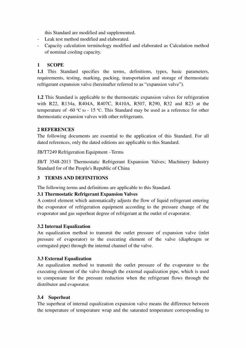
M/s Danfoss Industries Pvt. Ltd. comments is March 31, 2015 FOREWORD
(Adoption clauses to be added later on)
This Indian Standard was first published in 1983. The committee responsible to
formulate this standard decided to revise the existing Standard in view of the change
in the technology available at present. Accordingly, the main technical changes of this
Standard compared with IS 10594:1983, are as follows:
- The Standard is more comprehensive than IS 10594:1983 and new terminology as
described below here are included (but not limited to these only) and sequences of
many are changed.
- In the applicable scope, “thermostatic expansion valves for refrigeration with R12,
R22 and R502” is deleted, “thermostatic expansion valves for refrigeration with
R134a, R404A, R407C, R410A, R507, R290, R32 and R23” is added; and “this Standard is not applicable to the thermostatic expansion valves for automobile air
conditioner” is added. - Type, model and basic differentiating parameters are added. The terms and
definitions of “expansion valve opening superheat”, “expansion valve working superheat” and “hysteresis” are added; the term “capacity rating” is changed as “nominal cooling capacity”
- Classification method is added.
- Marking and color code is replaced with Mark, package, transportation and
storage.
- Test procedures as given in Appendix A is modified and new procedures are
added.
- The parameters “evaporation temperature range (high temperature, medium temperature, middle-low temperature and low temperature)” is added.
- The nominal working condition is modified.
- The contents required for “hydraulic strength test”, “air tightness test”, “nominal cooling capacity” and “working life” are modified; the requirements for “hysteresis” are added; and the corresponding test methods and inspection rules in
this Standard are modified and supplemented.
- Leak test method modified and elaborated.
- Capacity calculation terminology modified and elaborated as Calculation method
of nominal cooling capacity.
1 SCOPE
1.1 This Standard specifies the terms, definitions, types, basic parameters,
requirements, testing, marking, packing, transportation and storage of thermostatic
refrigerant expansion valve (hereinafter referred to as “expansion valve”).
1.2 This Standard is applicable to the thermostatic expansion valves for refrigeration
with R22, R134a, R404A, R407C, R410A, R507, R290, R32 and R23 at the
temperature of -60 ºC to - 15 ºC. This Standard may be used as a reference for other
thermostatic expansion valves with other refrigerants.
2 REFERENCES
The following documents are essential to the application of this Standard. For all
dated references, only the dated editions are applicable to this Standard.
JB/T7249 Refrigeration Equipment –Terms
JB/T 3548-2013 Thermostatic Refrigerant Expansion Valves; Machinery Industry
Standard for of the People's Republic of China
3 TERMS AND DEFINITIONS
The following terms and definitions are applicable to this Standard.
3.1 Thermostatic Refrigerant Expansion Valves
A control element which automatically adjusts the flow of liquid refrigerant entering
the evaporator of refrigeration equipment according to the pressure change of the
evaporator and gas superheat degree of refrigerant at the outlet of evaporator.
3.2 Internal Equalization
An equalization method to transmit the outlet pressure of expansion valve (inlet
pressure of evaporator) to the executing element of the valve (diaphragm or
corrugated pipe) through the internal channel of the valve.
3.3 External Equalization
An equalization method to transmit the outlet pressure of the evaporator to the
executing element of the valve through the external equalization pipe, which is used
to compensate for the pressure reduction when the refrigerant flows through the
distributor and evaporator.
3.4 Superheat
The superheat of internal equalization expansion valve means the difference between
the temperature of temperature wrap and the saturated temperature corresponding to
3
the pressure of refrigerant pressure at the outlet of the expansion valve. The superheat
of external equalization expansion valve means the difference between the
temperature of temperature wrap and the saturated temperature corresponding to the
connection of external equalization pipe (low pressure-side pressure).
3.5 Static Superheat
A value set to control the heat generating in the process from closing to opening the
expansion valve or from opening to closing the expansion valve.
3.6 Opening Superheat
The superheat required for opening the expansion valve to the degree corresponding
to the nominal cooling capacity.
3.7 Working Superheat
The sum of static superheat and opening superheat of the expansion valve.
3.8 Sub Cooled (Flash Gas Free) Liquid
The liquid refrigerant cooled to below the saturated temperature under a certain
pressure.
3.9 Pressure Drop
The difference between the inlet pressure and outlet pressure of the expansion valve.
3.10 Hysteresis
The difference between the opening superheat and closing superheat of the expansion
valve in the same refrigerant flow.
3.11 Nominal Cooling Capacity
The refrigerant flow through the expansion valve multiplied by the difference between
the enthalpy value at the inlet of the expansion valve and the saturated steam enthalpy
value at the evaporation temperature under the specified test condition of cooling
capacity.
4 TYPE, MODEL AND BASIC PARAMETERS
4.1 Type
4.1.1 By equalization method: internal equalization, external equalization
4.1.2 By flow direction: unidirectional flow and bidirectional flow
4.1.3 By refrigerant: R22, R134a, R404A, R407C, R410A, R507, R507A, R290,
R23 and R32.
4.1.4 By flow opening type: single flow opening, equalized flow opening

4.1.5 By connection method: welding, thread, flange
4.1.6 By flow-through method: straight-through flow and angle type
4.1.7 By pressure-limiting method: general and pressure limiting
4.1.8 By the installation method of temperature-sensing element: remote
temperature-sensing element, internal temperature-sensing element.
4.2 Model
The model of expansion valve can be determined by the manufacturer at its own
discretion, but the nominal cooling capacity of the expansion valve shall be reflected
in the model.
4.3 Basic Parameters
4.3.1 Range Of Evaporation Temperature of The Expansion Valve
The expansion valve shall work normally under the following conditions:
a) Range of evaporation temperature (high temperature): -10ºC-15ºC
b) Range of evaporation temperature (medium temperature): 25ºC-10ºC;
c) Range of evaporation temperature (middle-low temperature): -40ºC-10ºC
d) Range of evaporation temperature (low temperature): -60ºC- -25ºC
4.3.2 The nominal cooling capacity of the expansion valve shall be determined
according to the nominal working conditions in Table 1.
Table 1 Nominal Working Conditions
Unit: ºC
Nominal
working
condition
Temperature of liquid
refrigerant entering the
expansion valve
Condensing
temperature a
Evaporation
temperature b
Static
superheat
of
expansion
valve
Opening
superheat of
expansion
valve
1
34
38
5
4
4
2 -7
3 -23
4 -40 a Measured at the inlet of expansion valve, the condensing temperature of the mixed refrigerants is the
condensing bubble point temperature. b Measured at the outlet of expansion valve (internal equalization type) or at the external equalization
pipe of expansion valve (external equalization type), the evaporation temperature of mixed
refrigerants is the evaporation dew point temperature.
5
5 REQUIREMENTS
5.1 General Requirement
Expansion valves shall be manufactured according to the pattern and technical
documents approved by regulated procedures.
5.2 Adjusting Range of Static Superheat
After the test, the adjusting range of static superheat for expansion valves shall be 0K
~ 8K.
5.3 Hydraulic Strength Test
5.3.1 Pressure Endurance Test
Expansion valve shall to be pressure tested without leakage or deformation.
5.3.2 Burst Test
Expansion valve shall be pressure tested and free of leakage or cracking.
5.4 Tightness Test
The tightness can be tested by helium.
The leakage rate of expansion valves shall be less than 6.4 ×10⁻⁶
mbar·L/s, and the
leakage rate of the power head shall be less than 1 ×10⁻⁶
mbar·L/s.
5.5 Environmental Heat Resistance
During the test of environmental heat resistance, the temperature-sensing element of
expansion valves shall be free of leakage.
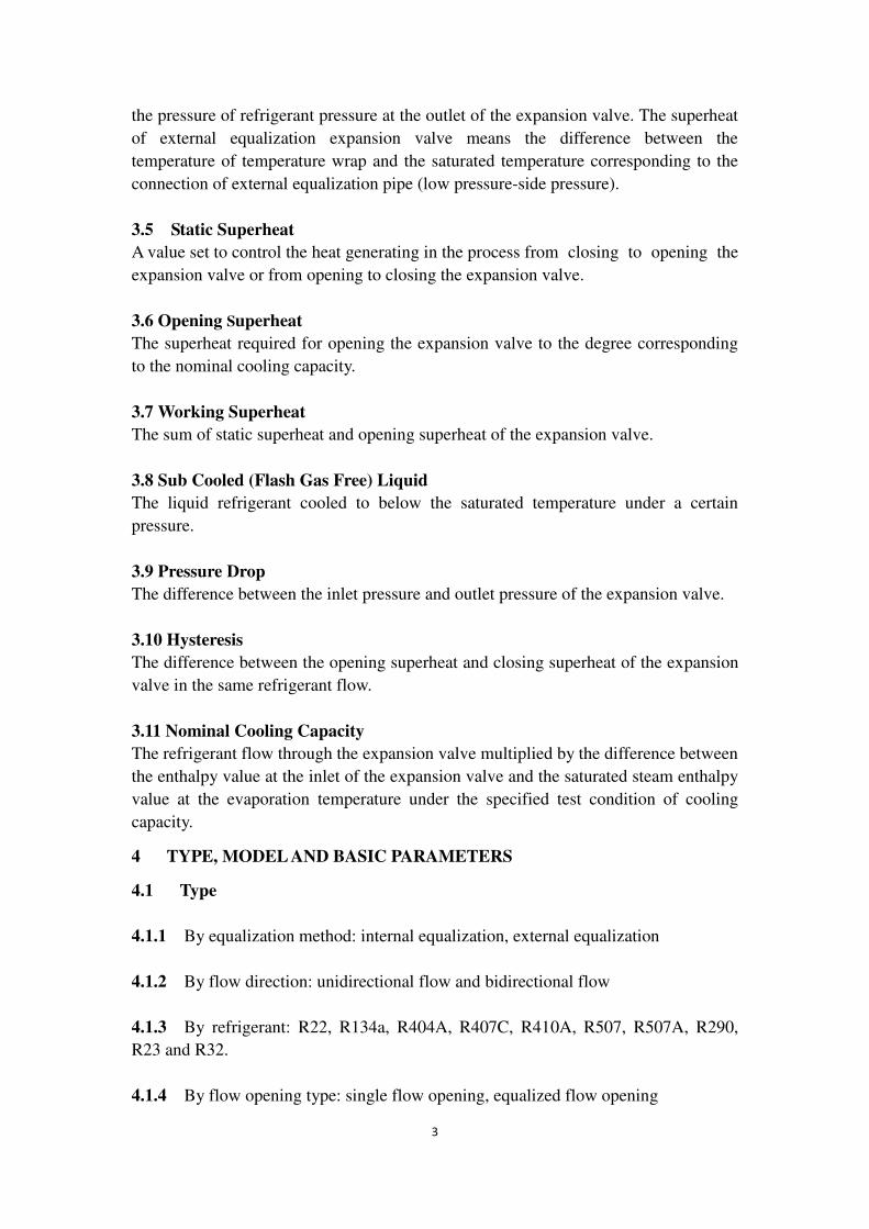
5.6 Leakage Rate of External Equalization Pipe
The leakage rate of external equalization pipe for expansion valves shall comply with
the stipulations in Table 2.
Table 2 Leakage Rate of External Equalization Pipe of Expansion Valves
Nominal cooling capacity (Q)
kW
Internal leakage rate
mL/min
Q≤7 ≤100
7<Q≤70 ≤150
Q>70 ≤200

5.7 Ex-Factory Static Superheat
After the test of ex-factory static superheat, the static superheat of expansion valves
shall conform to the requirements of static superheat in Table 1 or the contractual
specifications.
5.8 Internal Leakage of Throttle Opening
The actual leakage rate of the throttle opening of expansion valves shall be not more
than 1percent of the nominal flow rate.
5.9 Nominal Cooling Capacity
The measured cooling capacity of expansion valves shall not be less than 95 percent
of the nominal cooling capacity. The forward and reverse cooling capacity of
bidirectional expansion valves shall not be less than 95 percent of the nominal cooling
capacity. The maximum measured cooling capacity shall not be less than 120 percent
of the nominal cooling capacity.
5.10 Extension Cooling Capacity
For expansion valve of each model, it’s required to provide the extension cooling capacity data, namely, the cooling capacity at different evaporating temperatures and
pressure drops (or different condensing temperatures).
5.11 Hysteresis
The measured hysteresis of the expansion valves shall not be more than 2K or shall
comply with the contractual specification.
5.12 Vibration Resistance
After vibration resistance test, the expansion valves shall function properly and the
retested static superheat shall reach the original default value.
5.13 Working Life
After the working life test, the expansion valves shall function properly and the
retested static superheat shall reach the original default value.
5.14 Lifetime of Capillary
The capillary should withstand minimum ten bending cycle.
6 TEST METHODS
6.1 Test Conditions
6.1.1 Test Apparatus
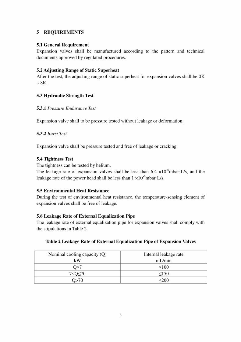
6.1.1.1 The air flow test principle for expansion valves with a remote
7
temperature-sensing element is as shown in Fig 1.
1——Pressure gauge; 2——Manual valve; 3——Pressure regulator; 4——Tested
expansion valve; 5——External equalization pipe; 6——Flow measuring instrument;
7——Thermostatic bath.
Figure 1 Schematic Diagram of Air Flow Test for Expansion Valves with a Remote
Temperature-Sensing Element
6.1.1.2 Air flow test principle for expansion valves with an internal
temperature-sensing element is as shown in Fig 2.
1——Pressure gauge; 2——Manual valve; 3——Pressure regulator; 4——Tested
expansion valve; 5——Flow measuring instrument; 6——Thermostatic bath.
Figure 2 Air Flow Test Principle Diagram for Expansion Valves with an Internal
Temperature-Sensing Element
6.1.1.3 Refrigerant flow test principle for expansion valves with a remote
temperature-sensing element is as shown in Fig 3.
Air flow Vent
Air flow
Vent

1——Flow measuring instrument; 2,3——Liquid level mirror; 4——Manual throttle
valve;
5——External equalization pipe; 6——Thermostatic bath; 7——Tested expansion
valve;
T1, T2, T3——Thermometer; M1,M 2, M 3 ——Pressure gage
Figure 3 Schematic Diagram of Refrigerant Flow Test for Expansion Valves with a
Remote Temperature-Sensing Element
6.1.1.4 Refrigerant flow test principle for expansion valves with an internal
temperature-sensing element is as shown in Fig 4.
1——Auxiliary evaporator; 2——Manual throttle valve; 3——Flow measuring
instrument;
4——Liquid level mirror; 5——Tested expansion valve;
T1, T2, T3 ——Thermometer; M1,M 2, M 3 ——Pressure gauge.
Figure 4 Schematic Diagram of Refrigerant Flow Test for Expansion Valves with an
Internal Temperature-Sensing Element
6.1.1.5 The leakage test principle of the external equalization pipe is as shown in
Fig 5.
Refrigerant vapor Liquid inlet Enter evaporate
Liquid inlet Enter evaporate
Thermal insulation material

9
1——Pressure regulator; 2——Tested expansion valve; 3——Manual valve;
4——sink; 5——Flow measuring instrument; 6——External equalization pipe; 7-
——Manual valve.
M1, M 2, —Pressure gauge.
Figure 5 Leakage Test Principle for External Equalization Pipe
6.1.1.6 The working life test principle for expansion valves is as shown in Fig
6.
1——Regulator; 2——Container; 3——Magnetic valve; 4——Manual valve;
5——Magnetic valve; 6——Manual valve; 7——Silencer; 8——Thermostatic bath;
9——Counter; 10——Pressure controller; 11——Tested expansion valve.
Figure 6 Schematic Diagram of Working Life Test for Expansion Valves
6.1.2 Test Working Conditions
According to the types of expansion valves, it’s required to choose test working conditions according to Table 1.
6.1.3 General Provisions For Apparatus And Instruments
Apparatus and instruments for tests shall pass the calibration by the legal
measurement and inspection departments and shall be within the validity.
6.1.4 Type And Accuracy Of Apparatus And Instruments
The type and accuracy of apparatus and instruments for tests shall abide by the
Air source
Air flow

stipulation in Table 3.
Table 3 Type and Accuracy of Apparatus and Instruments
Category Type Accuracy
Thermometric instrument Mercury-in-glass
thermometer, electric
resistance thermometer,
thermocouple
Air temperature: ±0.3ºC
Refrigerating system
temperature:±0.1ºC
Flow control measuring
instrument
Record, indication,
accumulation, etc.
Measuring flow ±1.0%
Refrigerant pressure
measuring instrument
Pressure gage, transmitter Measuring pressure ±2.0%
Time measuring instrument Chronograph Measuring time ±0.2%
6.1.5 Permissible deviation for the reading value of test working condition parameters
When the expansion valve is subject to the working conditions test, the permissible
deviation for the reading value of test condition parameters shall comply with the
stipulation in Table 4.
Table 4 Permissible Deviation for the Reading Value of
Test Condition Parameters
Test parameters Maximum deviation
between measured value
and specified value
Maximum deviation between the
measured values and the average
value
The temperature of
liquid refrigerant
entering the
expansion valve
±3ºC ±2ºC
The pressure of
refrigerant entering
the expansion valve
±2% ±1%
Refrigerant
evaporating
temperature
±3ºC ±1ºC
Refrigerant back
pressure *
±2% ±1%
Flow of refrigerant
and secondary
refrigerant
±5% ±2%
* When measuring the refrigerant pressure corresponding to the evaporating
temperature, the permissible deviation of the former shall correspond to that of the
11
latter, namely, ensure that the maximum deviation between the evaporating
temperature corresponding to the refrigerant pressure and the specified value shall be
±3ºC and the maximum deviation of the measured values to the average value shall
be ±1ºC.
6.2 Test Requirements
6.2.1 In the flow test apparatus for the expansion valve, if the oil content of its liquid
refrigerant-oil mixture is no more than 2 percent there is no need to amend the cooling
capacity according to the oil content.
6.2.2 In the test apparatus, a certain straight-line distance shall be kept between the
inlet and outlet pipes for expansion valves horizontally. The length of the straight
section of the inlet pipe shall be more than six times of the inner diameter of the pipe
and that of the straight section of the outlet pipe shall be more than six times of the
inner diameter of the pipe. The test point of temperature and pressure shall be set at a
distance within the six times of the inner diameter of inlet and outlet pipes from the
inlet and outlet of the expansion valve under the test of maximum capacity by the
equipment.
6.3 Test For Adjusting Range of Static Superheat
Install the expansion valves on the apparatus shown in Fig 1 or Fig 2 and place the
temperature-sensing wrap in the thermostatic bath (the temperature of the thermostatic
bath is the evaporating temperature under the nominal cooling working condition+
4ºC or complies with the contractual specification); adjust the inlet pressure of the
expansion valve to the refrigerant saturation pressure corresponding to the condensing
temperature in Table 1 or the refrigerant saturation pressure corresponding to the
temperature specified by the user. During the test, always make the air flow flowing
through the flow measuring instrument correspond to the minimum opening flow of
the tested expansion valve and then rotate the adjusting bolt to the loosest position and
the difference value between the saturation temperature corresponding to the outlet
pressure is the minimum superheat; and rotate the adjusting bolt to the tightest
position and the difference between the saturation temperature corresponding to the
outlet pressure and the temperature of the thermostatic bath is the maximum superheat;
the difference between the maximum superheat and minimum superheat is the
adjusting range of static superheat.
6.4 Hydraulic Strength Test
6.4.1 Pressure Endurance Test
Connect the valve to air or liquid source and increase the pressure gradually up to at
least 1.1 times of max. working pressure and maintain for one minute. Tested valve
shall fulfill the requirement of 5.3.1.
6.4.2 Burst Test

Under safety protections connect the valve to liquid source and increase the pressure
gradually to 5 times of max. working pressure for maintaining 3 min. The tested
valve shall fulfill the requirement of 5.3.2.
6.5 Test for Air Impermeability
Connect the valve to helium source with pressure not lower than 1.0 MPa and make
sure to test the leakage rate of the valve and the power head. The leakage rate shall
fulfill the requirement of 5.4.
6.6 Test For Environmental Heat Resistance
Place the expansion valve in the water of 80 ± 2ºC (temperature-sensing wrap of the
expansion valve is aerated) or 55 ± 2 ºC (temperature-sensing wrap of the expansion
valve is filled with fluid), for 1 h.
6.7 Leakage Test of External Equalization Pipe
Install the expansion valve in the apparatus shown in Fig 5, switch off the manually
operated valve 3 and adjust the pressure regulator until the indicated value on pressure
gage M2 is 0.15 MPa. Measure the leakage passing through the external equalization
pipe.
6.8 Adjustment of Ex-Factory Static Superheat
Install the expansion valve on the apparatus shown in Fig 1 or Fig 2 and place the
temperature-sensing wrap in the thermostatic bath (the temperature of the thermostatic
bath is the evaporating temperature under the nominal cooling working condition+ 4º
C or complies with the contractual specification); first adjust the inlet pressure to the
refrigerant saturation pressure corresponding to the condensing temperature in Table 1
or the refrigerant saturation pressure corresponding to the temperature specified by
the user and then adjust the adjusting bolt of the expansion valve to make the outlet
pressure be the saturation pressure corresponding to the evaporating temperature in
Table 1.
6.9 Inner Leakage Test of Throttle Opening
After adjusting the static superheat, switch off the manual throttle valve 2 in the outlet
of the expansion valve and test the leakage in the throttle opening.
6.10 Test For Nominal Cooling Capacity
6.10.1 Test For Refrigerant Flow
After adjusting the static superheat, install the expansion valve on the apparatus for
the test of the refrigerant flow shown in Fig 3 or Fig 4.
Adjust the test working conditions to make the outlet pressure of the expansion valve
be the refrigerant saturation pressure corresponding to the evaporating temperature in
Table 1; the temperature of the thermostatic bath gradually increases from the

13
evaporating temperature in Table 1 and the temperature increment is no less than 1ºC;
continue to increase the temperature of the thermostatic bath until the superheat
reaches 10ºC; then gradually reduce the temperature of the thermostatic bath until the
mass flow rate of the refrigerant reaches 0. Record the temperature values of the
temperature-sensing wrap and the mass flow rate values of the refrigerant in the entire
process.
Draw a superheat-mass flow characteristic curve of the expansion valve; take the
average value of opening flow and closing flow under the same superheat as the
refrigerant mass flow value under the superheat and the difference value of the mass
flow at G2 and G1 is the nominal flow value of the expansion valve, as shown in
Figure 7.
Figure 7 Superheat-Cooling Flow Curve of Expansion Valve
6.10.2 Calculation Method of Nominal Cooling Capacity
According to the superheat- flow characteristic curve of the expansion valve as shown
in Fig 7, the calculation formula of the nominal cooling capacity for the expansion
valve can be got:
Q= (G2—G1) × (h2—h1) ..............................................(1)
G2= (q2+q2’) /2...............................................(2)
G1= (q1+q1’) /2...............................................(3)
where:
Q = Nominal cooling capacity of the expansion valve, kW;
G1 = Average mass flow at the initial point (superheat is the static superheat)
of the expansion valve, kg/s;
G2 = Average mass flow at the nominal point (superheat of this point is the
Refrigerant flow
Close the valve
Open the valve
Superheat
Static superheat 4ºC Opening superheat 4ºC

sum of the static superheat and the opening superheat) of the expansion
valve, kg/s;
q1= Opening mass flow at the initial point of the expansion valve, kg/s;
q1’ = Closing mass flow at the initial point of the expansion valve, kg/s;
q2= Opening mass flow at the nominal point of the expansion valve, kg/s;
q2’= Closing mass flow at the nominal point of the expansion valve, kg/s;
h1= Specific enthalpy of the liquid refrigerant entering the expansion valve,
kJ/kg;
h2= Specific enthalpy of the saturated gas refrigerant vented from the
evaporator, kJ/kg.
6.10.3 Examples For Computing
Please refer to Table 5 for the test and calculating parameters for a expansion valve
under the test conditions.
Table 5 Examples of Test and Calculating Parameters
Used refrigerant R22
Test conditions Nominal working conditions
Opening mass flow at the initial point of
the expansion valve kg/s
0.0069
Closing mass flow at the initial point of
the expansion valve kg/s
0.0089
Opening mass flow at the nominal point
of the expansion valve kg/s
0.144
Closing mass flow at the nominal point of
the expansion valve kg/s
0.172
Measured temperature of the liquid
refrigerant entering the expansion valve
ºC
34.5
Measured upstream pressure of the
expansion valve kpa/condensing
temperature ºC
1461/38
Specific enthalpy of the liquid refrigerant
entering the expansion valve kJ/kg
242.45
Measured outlet pressure of the
expansion valve kpa/evaporating
temperature ºC
587/5.2
Specific enthalpy of the saturated gas
refrigerant vented from the evaporator
kJ/kg
407.22
Then, according to the formula (1), (2) and (3), calculate the nominal cooling capacity
of the expansion valve:
15
Q=[(0.172+0.144)/2-(0.0069+0.0089)/2]×(407.22-242.45)kW=24.73kW
6.11 Hysteresis
According to the test in 6.10, get the change of superheat when the expansion is open
and closed under the same cooling capacity, as shown in Figure 7.
6.12 Test For Vibration Resistance
Fix the expansion valve on the vibration test machine; conduct the up-and-down
vibration test and front-and-back vibration test for respective 2 h under 25Hz and
1.5mm amplitude and the retest the static superheat.
6.13 Test for Working Life
Install the expansion valve on the apparatus shown in Fig 6 and then close the inlet of
the valve. Place the temperature-sensing wrap in the 30 ºC ± 1ºC thermostatic bath.
The test medium is clean and dry compressed air. Switch on the magnetic valve 3 and
make the air pass through the diaphragm or the downside of the corrugated pipe, and
then close the valve. Close the magnetic valve 3 and switch on the magnetic valve 5
and make the diaphragm move up and down with full valve stroke. Through adjusting
the opening and closing time of the needle valve and magnetic valve, control the gas
pressure and make it change under a certain frequency (for the fluctuation range of the
gas pressure, the low pressure is the refrigerant pressure corresponding to the
minimum evaporating temperature of the expansion valve (at minimum “0” bar atmospheric) and the high pressure is the refrigerant pressure under 30ºC); the
frequency shall be no less than 10 times/min during the process of repeated movement
200000 times.
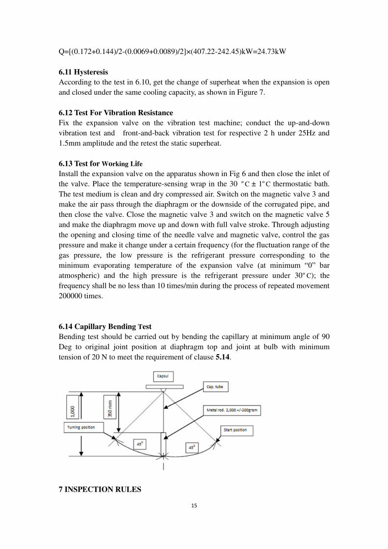
6.14 Capillary Bending Test
Bending test should be carried out by bending the capillary at minimum angle of 90
Deg to original joint position at diaphragm top and joint at bulb with minimum
tension of 20 N to meet the requirement of clause 5.14.
7 INSPECTION RULES

7.1 Ex-Factory Inspection
It’s required to conduct ex-factory inspection to every expansion valve and the
inspection items shall abide by the stipulation of Table 6.
Table 6 Inspection Items
No. Items
Ex-factory
inspection
Sampling
inspection
Type
test Requirements
Test
methods
1 Adjusting range
of static
superheat
√
√
√
5.2 6.3
2 Air tightness 5.4 6.5
3 Leakage in
external
equalization
pipe
5.6 6.7
4 Ex-factory static
superheat 5.7 6.8
5 Pressure
endurance test 5.3.1 6.4.1
6 Internal leakage
of throttle
opening
_
5.8 6.9
7 Nominal cooling
capacity 5.9 6.10
8 Hysteresis 5.11 6.11
9 Capillary life 5.14 6.14
10 Burst strength
_
5.3.2 6.4.2
11 Environmental
heat resistance 5.5 6.6
12 Extension
cooling capacity 5.10 6.10
13 Vibration
resistance 5.12 6.12
14 Working life 5.13 6.13
Note: items marked with “√” are those that needs inspection and items marked with “—” are those that don’t
need inspection.
7.2 Sampling Inspection
17
7.2.1 The expansion valves produced in batch shall be subject to sampling inspection.
The lot size, sampling plan, inspection level and acceptable quality level shall be
determined by the quality inspection department of the manufacturer.
7.2.2 Expansion valves shall be sampled from the qualified products in ex-factory
inspection and inspection items and test methods shall comply with the stipulation in
Table 6.
7.3 Type Test
7.3.1 When there are significant improvements in new products or approved products,
type test shall be conducted to the first product. Inspection items shall comply with
the stipulation of Table 6.
7.3.2 In the case of faults during the type test, it’s required to retest after the faults are removed.
8 MARKING, PACKAGING, TRANSPORTATION AND STORAGE
8.1 Marking
8.1.1 Every product or packing case shall be marked with:
a) Product name, specifications, model and quantity; and
b) Manufacturer’s name.
8.1.2 The certificate of inspection shall be printed with the product model and name,
manufacturing number, inspection date and implementing standards of inspection, etc.
8.2 Packaging
The package shall ensure the products won’t be damaged during transportation and storage.
8.3 Transportation
During the transportation of products, it’s required to avoid collision, throw, dropping, direct exposure to the rain and chemical pollution.
8.4 Storage
Products shall be stored in a dry and ventilated warehouse without corrosive gas.
9 BIS CERTIFICATION MARKING
9.1 Each thermostatic expansion valve may also be marked with the Standard Mark.
9.2 The use of the Standard Mark is governed by the provisions of Bureau of Indian

Standards Act, 1986 and the Rules and Regulations made thereunder. The details of
conditions under which a Iicence for the use of the Standard Mark may be granted to
the manufacturers or the producers may be obtained from the Bureau of Indian
Standards.

ANNEX
FORMAT FOR SENDING COMMENTS ON BIS DOCUMENTS
(Please use A4 size sheet of paper only and type within fields indicated. Comments
on each clauses/sub-clauses/table/fig. etc be started on a fresh box. Information in
Column 4 should include reasons for the comments and suggestions for modified
wording of the clauses when the existing text is found not acceptable. Adherence to
this format facilitates Secretariat’s work)
Doc. No.: ______________ TITLE: ________________________________________
LAST DATE OF COMMENTS: ____________
NAME OF THE COMMENTATOR/ORGANIZATION: _________________________
Sl.
No.
Clause/Subclause/
para/table/fig.
No. commented
Commentator/
Organization/
Abbreviation
Type of Comments
(General/Editorial/
Technical)
Justification
Proposed
change