Mechanical Engineering and Aeronautics Syllabus
46
Mechanical Engineering and Aeronautics Part 2 Applied Thermodynamics (24 lectures) Syllabus 1. Power Generation (5 – 6 lectures) Performance criteria for heat engines (thermal efficiency and work ratio). Ideal and Real Cycles for Reciprocating Engines, Gas Turbines and Simple Steam Power Plant. 2. Refrigeration (5 lectures) Reversed Carnot Cycle, Ideal Vapour-Compresion Refrigeration Cycle, Real Vapour-Compression Cycle from reversed Rankine Cycle. 3. Combustion (6 lectures) Fuels, Reactions, Stoichiometry, Heats of Reaction, Equilibrium, Adiabatic Flame Temperature 4. Heat Transfer (6 lectures) Conduction, Forced and Natural Convection, Radiation, Combined modes of heat transfer, Heat exchangers Assessment: An invigilated exam carrying a weighting of 0.7, and assessed coursework with a weighting of 0.3
Transcript of Mechanical Engineering and Aeronautics Syllabus

Mechanical Engineer ing and Aeronautics
Par t 2 Applied Thermodynamics (24 lectures)
Syllabus 1. Power Generation (5 – 6 lectures) Performance criteria for heat engines (thermal efficiency and work ratio). Ideal and Real Cycles for Reciprocating Engines, Gas Turbines and Simple Steam Power Plant. 2. Refr igeration (5 lectures) Reversed Carnot Cycle, Ideal Vapour-Compresion Refrigeration Cycle, Real Vapour-Compression Cycle from reversed Rankine Cycle. 3. Combustion (6 lectures) Fuels, Reactions, Stoichiometry, Heats of Reaction, Equilibrium, Adiabatic Flame Temperature 4. Heat Transfer (6 lectures) Conduction, Forced and Natural Convection, Radiation, Combined modes of heat transfer, Heat exchangers Assessment: An invigilated exam carrying a weighting of 0.7, and assessed coursework with a weighting of 0.3

1. Internal Combustion Engines The basic components of a reciprocating engine are shown in the figure below.
Intake Valve
Exhaust Valve
Stroke
Bore TDC
BDC
Connecting Rod (Length l)
Crank Radius R
Two/Four Stroke Internal Combustion Engines: 1. The highest position of the piston is called
Top Dead Centre (TDC:- Position corresponding to minimum cylinder volume).
2. The minimum volume formed in the cylinder when the piston is at TDC is called the Clearance Volume.
3. The lowest position of the piston is called Bottom Dead Centre (BDC:- position corresponding to maximum cylinder volume).
4. The diameter of the piston is called the Bore.
5. The volume displaced by the piston as it moves between TDC and BDC is called the Displacement Volume.
6. The fuel/air mixture is drawn into the cylinder through the Intake Valve.
7. The combustion products are expelled from the cylinder through the Exhaust Valve.
8. The ratio of the maximum volume formed in the cylinder to the minimum volume is called the Compression Ratio r of the engine.

The compression ratio r = Vmax/Vmin = VBDC/VTDC. The height of the piston relative to the centre of the crankshaft as a function of crankshaft angle is given by: The Mean Effective Pressure is the fictitious pressure, which, if acted on the piston throughout the entire power stroke, would produce the same amount of net work as that produced during the actual cycle. MEP = Wnet/(Vmax-Vmin) The mean effective pressure (MEP) can be used to compare the performance of reciprocating engines of equal size.
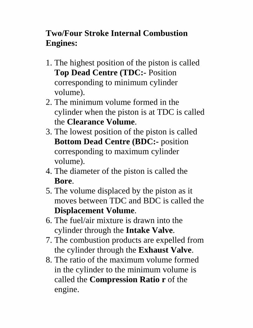
A P-V diagram for a realistic spark ignition engine gas cycle is shown below:
Intake
Exhaust
Exhaust Valve Opens
Intake Valve Opens
Ignition
End of Combustio
P
Patm
Volume
TDC BDC

A P-V diagram for an ideal spark ignition engine gas cycle (Otto Cycle) is shown below:
qin
qout
2
3
4
1
Volume
P
BDC TDC

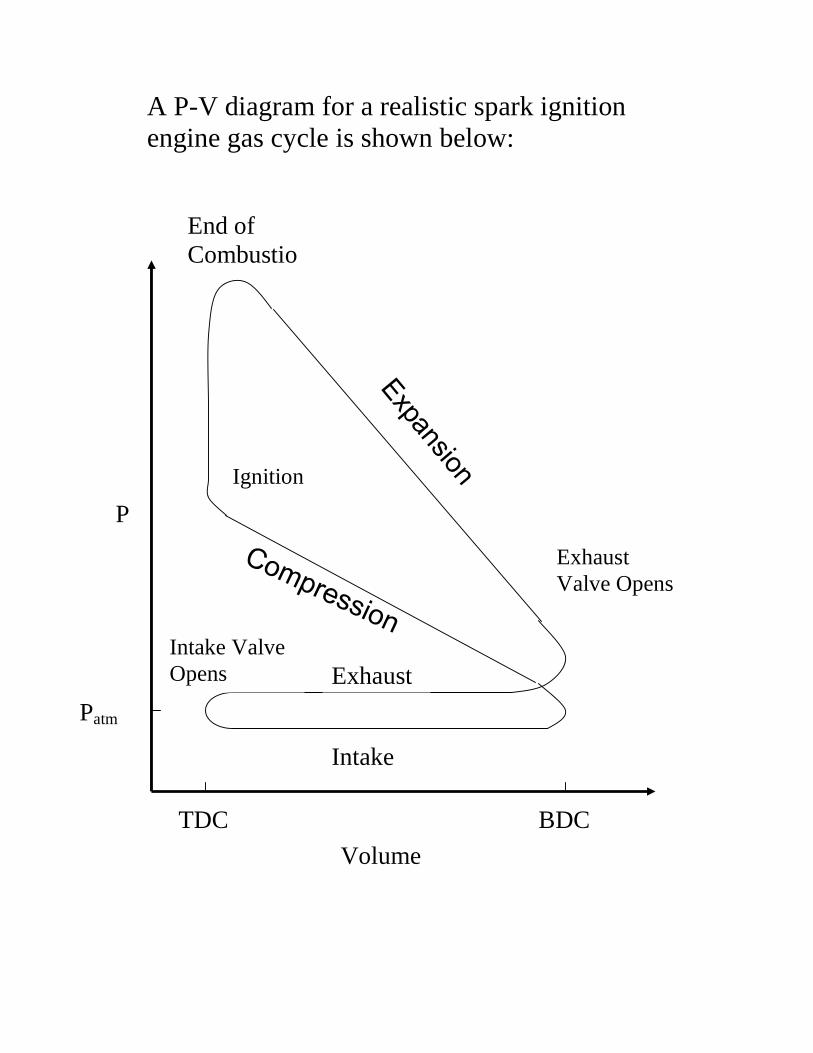
The Otto cycle consists of four internally reversible processes. 1 – 2: Isentropic compression during the compression stroke. 2 – 3: Constant volume heat addition. Combustion occurs almost instantaneously at constant volume, adding qin to the gas. 3 – 4: Isentropic expansion during the power stroke. 4 – 1: Constant volume heat rejection.
From the First Law of Thermodynamics, the change in the mass specific internal energy is given by the heat added to the system minus the work done by the system. ∆u = q - w qin = q23 = u3 - u2 = Cv(T3 - T2) qout = q41 = (u1 - u4) = Cv(T1 - T4) ηth,Otto = wnet/qin = 1 - qout/qin = 1 - (T4 - T1)/(T3 - T2)
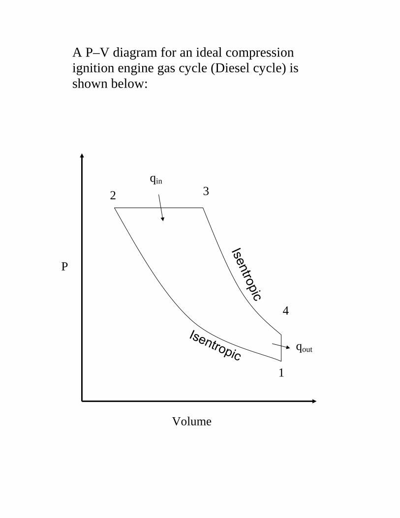
A P–V diagram for an ideal compression ignition engine gas cycle (Diesel cycle) is shown below:
1
4
3 2
Volume
qout
P
qin
The Diesel cycle consists of four internally reversible processes. 1 – 2: Isentropic compression during the compression stroke. 2 – 3: Constant pressure heat addition. Combustion occurs at constant pressure, adding qin to the gas. 3 – 4: Isentropic expansion during the power stroke. 4 – 1: Constant volume heat rejection.
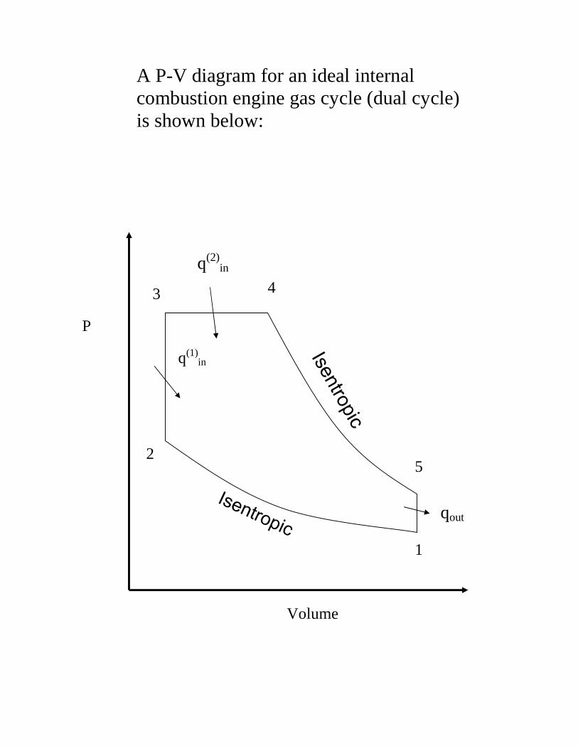
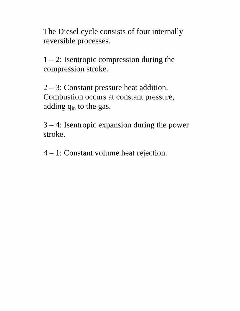
A P-V diagram for an ideal internal combustion engine gas cycle (dual cycle) is shown below:
q(2)in
q(1)in
Volume
qout
1
2
3 4
P
5

1. The Indicated Mean Effective Pressure (IMEP) is as defined earlier. Imep = wnet/(Vmax – Vmin) 2. The Brake Mean Effective Pressure
(BMEP) is the ratio of the brake work output to the swept volume.
Bmep = brake work output/swept volume 3. The mechanical efficiency of the engine ηm is the ratio of the bmep to imep. ηm reveals how much work is lost through bearing friction, and in driving essential items such as the oil pump. ηm = bmep/imep 1. The volumetric efficiency ηv is a measure of
the effectiveness of the induction and exhaust processes.
ηv = mass of air inhaled per cycle/mass of air to occupy swept volume at ambient conditions.

The Brayton Cycle – The Ideal Cycle for Gas Turbines Gas turbines usually operate on an open cycle. Fresh air at ambient conditions is drawn into the compressor where its temperature and pressure are raised. The high pressure air proceeds into the combustion chamber where the fuel is burned at high pressure. The resulting high temperature gases then enter the turbine where they expand to the atmospheric pressure, thus producing power. The exhaust gases are released, causing the cycle to be classified an open cycle.
Compresso
Combustion Chamber
Turbine
1
2 3
4 Fresh Air Exhaust Gases
Fuel

The open gas turbine cycle can be modelled as a closed cycle. This is the Brayton cycle. It is made up of four internally reversible processes. 1 - 2 Isentropic compression (in a compressor) 2 - 3 P = constant heat addition 3 – 4 Isentropic expansion (in a turbine) 4 – 1 P = constant heat rejection
1
2 3
4
S =
S = constant P
v
qin
qout
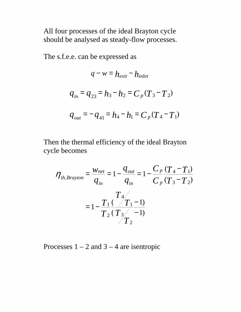
All four processes of the ideal Brayton cycle should be analysed as steady-flow processes. The s.f.e.e. can be expressed as
Then the thermal efficiency of the ideal Brayton cycle becomes
Processes 1 – 2 and 3 – 4 are isentropic
hh inletexitwq −=−
)( 232323 TTChhqq pin−=−==
)( 141441 TTChhqq pout−=−=−=
)(
)(11
23
14, TT
TTCC
qw
p
p
in
out
in
netBraytonth −
−−=−==η
)1
)1
(
(1
2
3
1
4
2
1
−−−=
TT
TT
TT

Example: A stationary power plant operating on an ideal Brayton cycle has a pressure ratio of 8. The gas temperature is 300 K at the compressor inlet and 1300 K at the turbine inlet. Utilising the air-standard assumptions and accounting for the variation of specific heats with temperature, determine (a) the gas temperature at the exits of the
compressor and the turbine, (b) the back work ratio (c) the thermal efficiency.
PPr
r
TT
PP
PP
TT
p
kk
p
Braytonth
kk
kk
1
2
1,
4
3
1
4
3
1
1
2
1
2
11
=
−=
=���
����
�=��
�
����
�=
−
−−
η
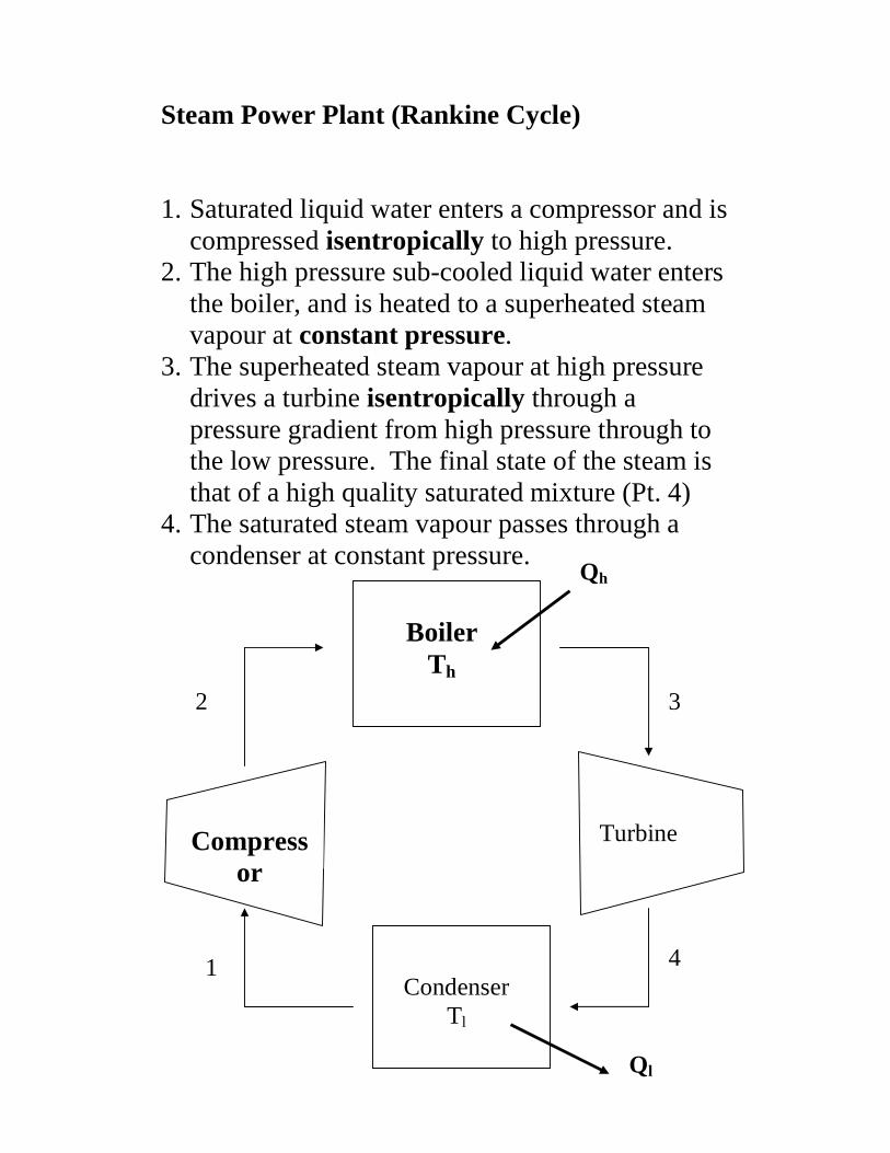
Steam Power Plant (Rankine Cycle)
1. Saturated liquid water enters a compressor and is
compressed isentropically to high pressure. 2. The high pressure sub-cooled liquid water enters
the boiler, and is heated to a superheated steam vapour at constant pressure.
3. The superheated steam vapour at high pressure drives a turbine isentropically through a pressure gradient from high pressure through to the low pressure. The final state of the steam is that of a high quality saturated mixture (Pt. 4)
4. The saturated steam vapour passes through a condenser at constant pressure.
Condenser Tl
Boiler Th
Turbine Compressor
1 4
3 2
Qh
Ql

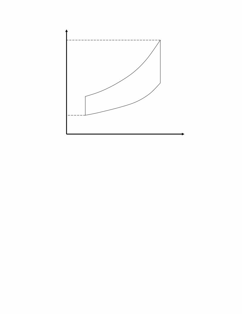
Schematic T-s Diagram for Simple Steam Power Plant (Ideal Rankine Cycle)
4
3
2
1 Ql
Qh
T
Specific Entropy s
Saturated Liquid
High Quality Saturated Mixture

From the Steady-flow Energy Equation, and ignoring changes in kinetic energy and potential energy of the working fluid (steam)
(1) Pump Work
(2) Heat Absorbed by Water in Boiler
(3) Work Done by Steam in Turbine
(4) Heat Lost by Water in Condenser
( )if
if
hhmWQ
hhwq
−=−
−=−
���
( ) 0
0
43
43
>−=>−=
hhmW
hhw
waterout
out
��
( ) 0
0
23
23
>−=>−=
hhmQ
hhq
waterin
in
��
( )( ) ( ) 0
0
2121
2121
<−=−=<−=−=
PPvmhhmW
PPvhhw
waterwaterin
in
���
( ) 0
0
41
41
<−=<−=
hhmQ
hhq
waterout
out
��
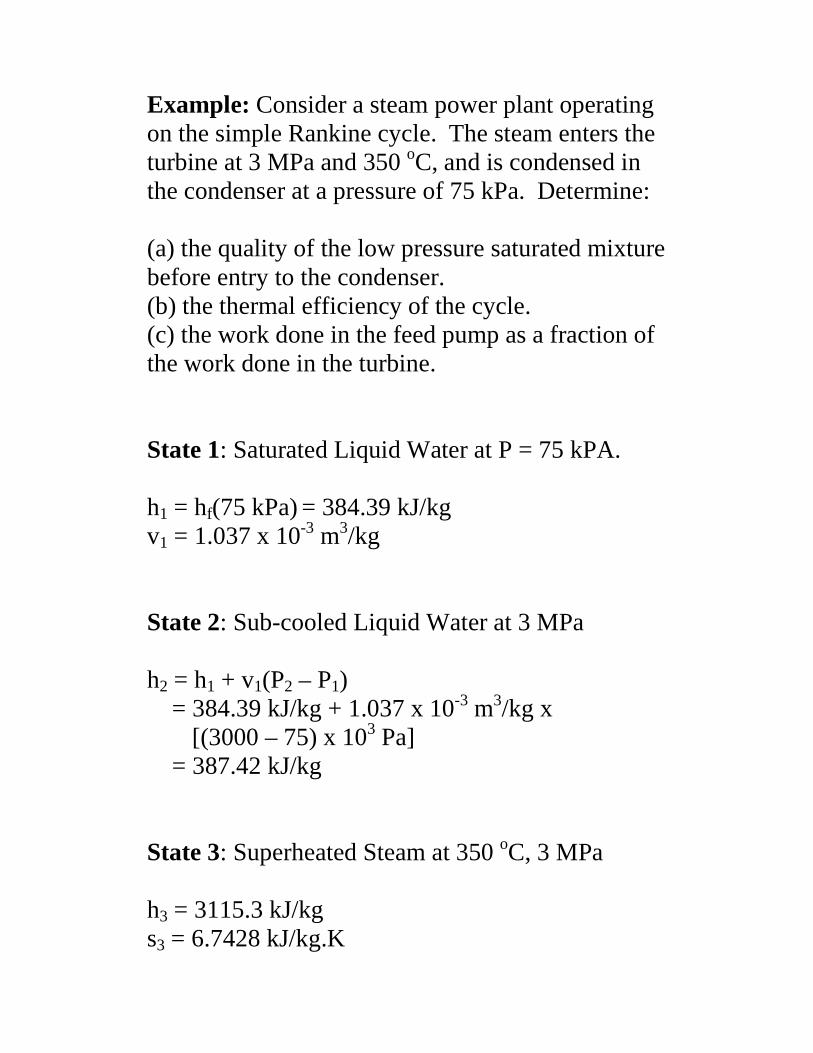
Example: Consider a steam power plant operating on the simple Rankine cycle. The steam enters the turbine at 3 MPa and 350 oC, and is condensed in the condenser at a pressure of 75 kPa. Determine: (a) the quality of the low pressure saturated mixture before entry to the condenser. (b) the thermal efficiency of the cycle. (c) the work done in the feed pump as a fraction of the work done in the turbine. State 1: Saturated Liquid Water at P = 75 kPA. h1 = hf(75 kPa) = 384.39 kJ/kg v1 = 1.037 x 10⁻³ m3/kg State 2: Sub-cooled Liquid Water at 3 MPa h2 = h1 + v1(P2 – P1) = 384.39 kJ/kg + 1.037 x 10⁻³ m3/kg x
[(3000 – 75) x 103 Pa] = 387.42 kJ/kg State 3: Superheated Steam at 350 oC, 3 MPa h3 = 3115.3 kJ/kg s3 = 6.7428 kJ/kg.K

State 4: High Quality Saturated Water Mixture at 75 kPa Isentropic expansion doing work on turbine s4 = s3 = 6.7428 kJ/kg.K
The quality 886.02434.6
213.17428.644 =−=
−=
fg
f
s
ssy
h4 = hf + y4.hfg = (384.39 + 0.886 x 2278.6) kJ/kg = 2403.2 kJ/kg (a) Already solved. y = 0.886. (b) Thermal Efficiency
26.088.2727
81.20181
1123
14
=−=
−−
−=−=−
==hh
hh
q
q
q
q
w
in
out
in
outin
in
netthη
(c)
( )
00426.01.712
03.3
/1.712/2.24033.3115
/03.3
43
121
==
=−=−=
=−=
turbine
feedpump
turbine
feedpump
w
w
kgkJkgkJhhw
kgkJPPvw

City University
Depar tment of Mechanical Engineer ing and Aeronautics
Advanced Energy Systems: Heat and Mass Transfer
Tutor ial 1: Ideal I .C. Engines, Gas Turbines
1. How do the efficiencies of the ideal Otto cycle and the Carnot cycle compare or the same temperature limits ?
2. An ideal Otto cycle has a compression ratio of 8. At the beginning of the compression process, air is at 100 kPa, and 30oC, and 840 kJ/kg of heat is transferred to air during the constant volume heat addition process. Taking into account the variation of specific heats with temperature, determine (a) the pressure and temperature at the end of the heat addition process, (b) the net work output, (c) the thermal efficiency, and (d) the mean effective pressure.
3. An ideal Otto cycle with air as the working fluid has a compression ratio of 8.
The minimum and maximum temperatures in the cycle are 290 K and 1650 K respectively. Accounting for the variation of specific heats with temperature, determine (a) the amount of heat transferred to air during the heat addition process, (b) the thermal efficiency, (c) the thermal efficiency of a Carnot cycle operating between the same temperature limits.
4. An air standard Diesel cycle has a compression ratio of 16 and a cutoff ratio of 2.
At the beginning of the compression process, air is at 100 kPa, and 17oC. Accounting for the variation of specific heats with temperature, determine (a) the temperature after the heat addition process, (b) the thermal efficiency, and (c) the mean effective pressure.
5. A four cylinder 4.5l diesel engine which operates on an ideal Diesel cycle has a
compression ratio of 16.5 and a cutoff ratio of 2.0. Air is at 20oC and 100kPa at the beginning of the compression process. Accounting for variation of specific heat with temperature, and assuming that the mechanical efficiency is 75%, determine how much power the engine will deliver at 2000rpm.

6. A simple Brayton cycle using air as the working fluid has a pressure ratio of 8, a
compressor inlet temperature of 300 K, and a turbine inlet temperature of 1000 K. Determine the required mass flow rate of air for a net power output of 40 MW, assuming both the compressor and turbine have an isentropic efficiency of (a) 100%, and (b) 80%.
7. Air enters the compressor of a gas turbine engine at 300 K and 100 kPa, where it
is compressed to 700 kPa and 580 K. Heat is transferred to air in the amount of 950 kJ/kg before it enters the turbine. For a turbine efficiency of 86%, determine (a) the fraction of the turbine work output used to drive the compressor, and (b) the thermal efficiency. Assume variable specific heats for air.
CITY University
School of Engineer ing
Mechanical Engineer ing and Aeronautics
Par t 2 Thermodynamics: Tutor ial 1
Tutorial Problems from
Thermodynamics: An Engineering Approach 4th Edition
Yunus A. Cengel and Michael A. Boles
Gas Power Cycles 8-31C, 8-33, 8-36, 8-37, 8-45, 8-46, 8-49, 8-50, 8-52, 8-73, 8-74, 8-75, 8-76, 8-79
Vapour and Combined Power Cycles 9-15, 9-16, 9-17, 9-20, 9-22
Depar tment of Mechanical Engineer ing and Aeronautics
Par t 2 Thermodynamics
Tutorial Problems from
Thermodynamics: An Engineering Approach 4th Edition
Yunus A. Cengel and Michael A. Boles
Gas Power Cycles
8-31C, 8-33, 8-36, 8-37, 8-45, 8-46, 8-49, 8-50, 8-52, 8-73, 8-74, 8-75, 8-76, 8-79
Vapour and Combined Power Cycles 9-15, 9-16, 9-17, 9-20, 9-22

Fuels and Combustion All matter is comprised of a limited number of elementary substances known as chemical elements. A chemical element is constructed of fundamental units called atoms. The atoms of an element are constructed of electrons, protons, and neutrons. The protons and neutrons bind together through the short range strong nuclear force, forming the atomic nucleus. Electrons move about the nucleus, forming a negatively charged shell about the positively charged nucleus. The electron shell about the nucleus gives the atom its size. The atomic nucleus is very small relative to the size of the atom. A typical nucleus has a diameter of 10-14 m, or 10-4 A. A typical atom has a diameter of 10-10 m to 10-9 m, or 1 A – 10 A. So the linear dimension of the atom is about 10 000 – 100 000 larger than the nucleus. Atoms rarely exist in isolation, and are usually found linked together in groups called molecules. In elements, all of the atoms linked together are identical. Compounds are formed when atoms of different elements are bound together. The atoms in a molecule are held together by inter-atomic forces. These forces are only effective over short distances. A consequence of the atomic and molecular construction of matter is that the ratio of the number of different atoms in a substance must be in simple, integral proportions e.g. 2:1 in the case of hydrogen and oxygen in water, and 4:1 in the case of hydrogen and carbon in methane. A mole of a substance is when the number of atoms or molecules comprising the substance equals Avogadro’s number (6.0225 x 10²³) i.e. there are 6.0225 x 10²³ molecules in 12 g of carbon-12, and the same number of water molecules in 18 g of water. A mole can also be described as that amount of a substance whose mass is numerically equal to its relative molecular mass. Fuels Any material that can be burned to release heat and energy is called a fuel. Fuels can exist in gaseous form, liquid form, or solid form. Most familiar fuels consist primarily of hydrogen and carbon. They are called hydrocarbon fuels, and are denoted by the formula CnHm.
Hydrocarbon fuels are classified chemically as: (1) The Aliphatic Series (2) The Aromatic Series

(3) Fuel Alcohols The Aliphatic Series There are three Aliphatic series whose formulae may be written overall as: Alkanes CnH2n+2 also known as Paraffins.
Alkenes CnH2n also known as Olefins. Alkynes CnH2n-2 also known as Acetylenes. Crude petroleum contains large quantities of paraffins, small quantities of olefins, and trace quantities of acetylenes. Alkanes exist as straight chain compounds or as isomers of these. The inter-atomic bonds are saturated, and therefore they are stable. Examples: Methane: CH4 Propane: C3H8 Octane (Straight): C8H18 2,2,4 Tr imethyl Pentane (Iso-octane):C5H9(CH3)3
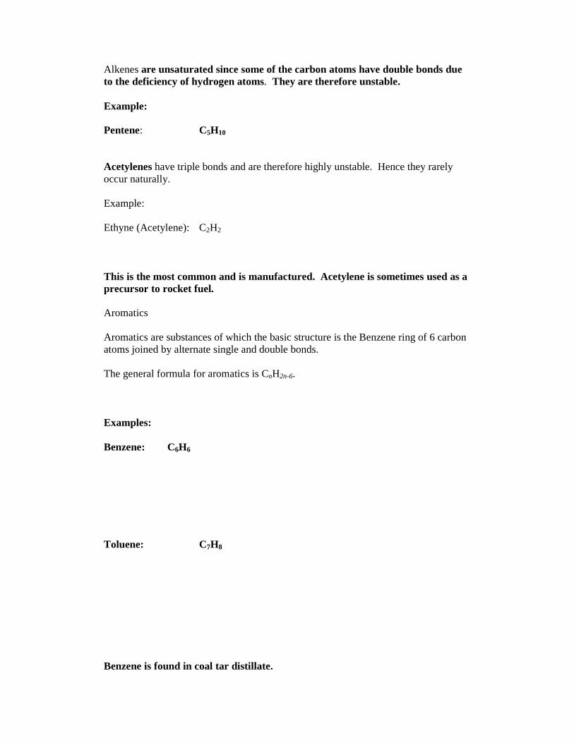
Alkenes are unsaturated since some of the carbon atoms have double bonds due to the deficiency of hydrogen atoms. They are therefore unstable. Example: Pentene: C5H10 Acetylenes have triple bonds and are therefore highly unstable. Hence they rarely occur naturally. Example: Ethyne (Acetylene): C2H2 This is the most common and is manufactured. Acetylene is sometimes used as a precursor to rocket fuel. Aromatics Aromatics are substances of which the basic structure is the Benzene ring of 6 carbon atoms joined by alternate single and double bonds. The general formula for aromatics is CnH2n-6. Examples: Benzene: C6H6 Toluene: C7H8 Benzene is found in coal tar distillate.

Alcohols These contain oxygen and are therefore not str ictly hydrocarbons. The following have been used as fuels. Methanol (Methyl Alcohol): CH4O Ethanol (Ethyl Alcohol): C2H6O Butanol (Butyl Alcohol): C4H10O In general, hydrocarbons with 5 or more carbon atoms in the basic molecule are liquids at normal atmospher ic conditions, while those with less than 5 atoms in the molecule are gaseous. Alcohols are an exception to the above rule. All alcohols are liquids at normal atmospher ic conditions. Combustion Combustion is a chemical reaction in which a fuel is oxidised and a large quantity of heat and energy is released. The oxidiser most often used in combustion reactions is the naturally occurring oxygen in air. Pure oxygen is sometimes used as an oxidiser in special applications.
On a mole or volume basis, dry air consists of 20.9% oxygen, 78.1% nitrogen, 0.9% argon, and small amounts of carbon dioxide, helium, neon, and hydrogen. In the analysis of combustion processes, atmospheric argon is treated as nitrogen, while the other atmospheric trace gases are disregarded. Therefore dry air is usually approximated as 21% oxygen, and 79% nitrogen by mole or volume proportion. Therefore each mole of atmospheric oxygen entering a combustion process is accompanied by 79/21 = 3.76 moles nitrogen.

Chemical Change We express the reactions of fuels in combustion processes by means of chemical equations. eg. Methane burning in oxygen to carbon dioxide and water
CH4 + 2O2 → CO2 + 2H2O (1) Each chemical element active in a reaction equation must be conserved. To obtain the correct number of moles combining, the number of moles of each element must balance on both sides of the reaction equation. i.e. the number of atoms of each element appearing on the RHS and the LHS of the equation must be equal. The following equations also balance:
3H2 + O2 → 2H2O + H2 (2)
2C2H2 + 6O2 → 2H2O + 4CO2 + O2 (3) Reaction equation (1) above gives the stoichiometr ic proportions i.e. the proportions of reactants that will produce complete combustion. Reaction equation (2) has insufficient oxygen, or too much fuel to produce complete combustion. This defines a r ich mixture. Reaction (3) has too much oxygen, or too little fuel to produce complete combustion. This defines a lean mixture. Given the following relative atomic masses: m(C ) =12, m(O) = 16, m(H) = 1, m(N) = 14, we may express these reactions on a molal basis: eg. Equation (1) 1 mole CH4 + 2 moles O2 → 1 mole CO2 + 2 moles H2O or on a gravimetr ic basis (mass basis) 0.016kg CH4 + 0.64kg O2 → 0.044kg CO2 + 0.036kg H2O Consider now reaction (3) above, written on a molal basis. 2 moles C2H2 + 6 moles O2 → 2 moles H2O + 4 moles CO2 + 1 mole O2
If this reaction was in air, we would write
2 moles C2H2 + 6.(1 mole O2 + 3.76 moles N2) → 2 moles H2O + 4 moles CO2 + 1 mole O2 + 22.6 moles N2
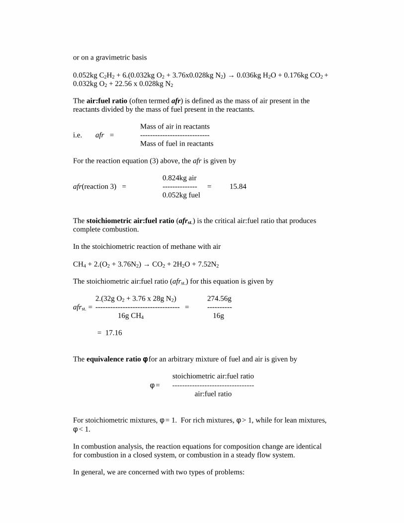
or on a gravimetric basis 0.052kg C2H2 + 6.(0.032kg O2 + 3.76x0.028kg N2) → 0.036kg H2O + 0.176kg CO2 + 0.032kg O2 + 22.56 x 0.028kg N2 The air :fuel ratio (often termed afr) is defined as the mass of air present in the reactants divided by the mass of fuel present in the reactants. Mass of air in reactants i.e. afr = ---------------------------- Mass of fuel in reactants For the reaction equation (3) above, the afr is given by 0.824kg air afr(reaction 3) = -------------- = 15.84 0.052kg fuel The stoichiometr ic air :fuel ratio (afrst.) is the critical air:fuel ratio that produces complete combustion. In the stoichiometric reaction of methane with air CH4 + 2.(O2 + 3.76N2) → CO2 + 2H2O + 7.52N2 The stoichiometric air:fuel ratio (afrst.) for this equation is given by 2.(32g O2 + 3.76 x 28g N2) 274.56g afrst. = ---------------------------------- = ---------- 16g CH4 16g = 17.16 The equivalence ratio φφφφ for an arbitrary mixture of fuel and air is given by
stoichiometric air:fuel ratio φ = ---------------------------------
air:fuel ratio For stoichiometric mixtures, φ = 1. For rich mixtures, φ > 1, while for lean mixtures, φ < 1. In combustion analysis, the reaction equations for composition change are identical for combustion in a closed system, or combustion in a steady flow system. In general, we are concerned with two types of problems:

1. Given the fuel and air supply, determine the combustion products, (possibly
combustion temperature). For this purpose, unless further information is supplied, assume: (i) All the carbon is burned to carbon monoxide (CO). (ii) The remaining oxygen is shared equally between the CO oxidising to CO2
and the hydrogen to H2O. Thus if the mixture is rich, the final products of combustion would comprise: CO, CO2, H2O, H2, and N2. If the fuel is gaseous, then Volumetric Analysis of Reaction = Molar Analysis of Reaction. 2. Exhaust Gas Analysis In this case the combustion products are known and it is required to determine the air:fuel ratio or composition of the fuel. Exhaust gas composition is normally given for dry gases only since it is assumed that any water vapour formed is condensed out during the analysis. Example: In an engine test, the dry volumetric analysis of the products was 5.27% CO2, 13.38% O2 and 81.35% N2. Assuming that the fuel is a pure hydrocarbon and that it is completely burnt, estimate the ratio of carbon to hydrogen in the fuel by weight and the afr by weight. Consider 100 moles of dry exhaust gases. The molal equation is aC + bH + c.(O2 + 3.76N2) → 5.27CO2 + 13.38O2 + 81.35N2 + dH2O Equating atoms on both sides of reaction equation Nitrogen: (3.76 x 2)c = 2 x 81.35 c = 21.6 Hydrogen: b = 2d Oxygen: 2c = (2 x 5.27) + (2 x 13.38) + d d = 5.9, b = 11.8 Carbon: a = 5.27 C:H by moles = 5.27:11.8 = 0.447 C:H by weight = 5.27 x 12:11.8 = 5.36 afr = 21.6 x 137.28:[(5.27 x 12) + 11.8] = 39.5

The First Law of Thermodynamics Applied to Combustion In general: dE = dQ – dW implies no restriction in the nature of the internal energy of the system. The restricted form: dU = dQ – dW only applies to a pure substance whose changes in state are solely due to heat and mechanical work transfer. The Pure Substance Definition: A pure substance is a substance which is a) homogeneous in composition, b) homogeneous in chemical aggregation, c) invariable in chemical aggregation. The Two Property Rule: The state of a pure substance of given mass can be fixed by specifying two properties provided that 1) the system is in equilibrium, 2) gravity, motion, electricity, magnetism, and capillarity are without significant
effects, 3) the two properties are independent. For this rule to be applicable the system must be a liquid or gas. If x, y, z are intensive properties of a system obeying these conditions then the two property rule may be expressed by a relationship of the form
z = f(x,y) It follows that tables or charts may be used to give any third intensive property in terms of two other intensive properties. For a pure substance let the internal energy have the symbol U and specific internal energy u. Then the total energy E of the substance is E = U + Terms accounting for gravity, motion, electricity, etc. For a pure substance we may write the First Law in the absence of these effects as
dU = dQ – dW
A chemical substance is one which is homogeneous in composition only and whose state is therefore also dependent on its chemical aggregation. For this we may write in general
dU’ = dQ – dW

In a combustion process where reactants combine to form products we may write:
U’pr – U’ r = Q – W Enthalpy of Formation and Enthalpy of Combustion In thermodynamics we are concerned with the changes in the energy of a system during a process, and not the energy values at particular states. This means that we can freely assign a value of zero energy for the internal energy or enthalpy of a substance at a reference state. When a process involves no changes in chemical composition, the reference state chosen has no effect on the results. When the process involves chemical reactions, the composition of the system at the end of the process is no longer the same as that at the beginning of the process. In this case it becomes necessary to have a common reference state for all substances. The chosen reference state is 25 oC, and 1 atmosphere, which is known as the standard reference state. Property values in the standard state of the substance are indicated by the superscript “ o” (such as ho and uo). eg. ho (N2) = 8669 J/mole When analysing reacting systems, we use property values relative to the standard reference state. Consider the formation of CO2 from its elements, carbon and oxygen, during a steady-flow combustion process. Both the carbon and oxygen enter the combustion chamber at the standard reference state (25 oC and 1 atmosphere). The CO2 formed during this process leaves the combustion chamber at the same reference state. The reaction of carbon in oxygen to form CO2 is an exothermic reaction (a reaction in which chemical energy is released in the form of heat). The heat released from the combustion chamber to the surroundings must be
Q = hproducts – hreactants = ∆h
∆h = -393.52 kJ/mole C

Since both the reactants and the products are at the same state, the enthalpy change during this process is solely due to the changes in the chemical composition of the system. This enthalpy change is experienced as heat generated by the change in the chemical composition of the system. Enthalpy changes are different for different reactions. The change in chemical energy during a reaction from reactants to products is referred to as the enthalpy of reaction. The enthalpy of reaction must be evaluated with the reactants and products at the same thermodynamic state. In combustion processes, the enthalpy of reaction is usually referred to as the enthalpy of combustion. The enthalpy of reaction (combustion) may be deduced from knowledge of the enthalpy of each reaction constituent. In this regard, we arbitrarily set the enthalpy of formation ho
f of all stable elements to zero at the standard reference state. Eg. ho
f (C) = hof (O2) = 0.
Now reconsider the formation of CO2 from its elements C and O2 at the standard reference state. The enthalpy change during this process was determined to be
hproducts – hreactants = ∆h = -393.52 kJ/mole
but hreactants = 0, since both reactants are at the standard reference state. Therefore the enthalpy of formation of CO2 at the standard reference state must be
hof (CO2) = -393.52 kJ/mole
The negative sign is due to the fact that the enthalpy of 1 mole of CO2 is 393.52 kJ less than the enthalpy of 1 mole of carbon and 1 mole of molecular oxygen at the same state.
O2
C(s)
CO2
25 oC,1 atm.
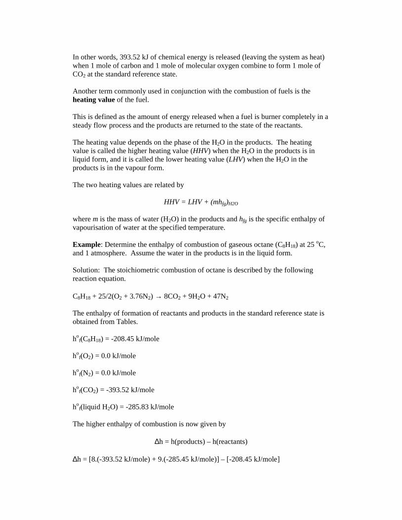
In other words, 393.52 kJ of chemical energy is released (leaving the system as heat) when 1 mole of carbon and 1 mole of molecular oxygen combine to form 1 mole of CO2 at the standard reference state. Another term commonly used in conjunction with the combustion of fuels is the heating value of the fuel. This is defined as the amount of energy released when a fuel is burner completely in a steady flow process and the products are returned to the state of the reactants. The heating value depends on the phase of the H2O in the products. The heating value is called the higher heating value (HHV) when the H2O in the products is in liquid form, and it is called the lower heating value (LHV) when the H2O in the products is in the vapour form. The two heating values are related by
HHV = LHV + (mhfg)H2O where m is the mass of water (H2O) in the products and hfg is the specific enthalpy of vapourisation of water at the specified temperature. Example: Determine the enthalpy of combustion of gaseous octane (C8H18) at 25 oC, and 1 atmosphere. Assume the water in the products is in the liquid form. Solution: The stoichiometric combustion of octane is described by the following reaction equation. C8H18 + 25/2(O2 + 3.76N2) → 8CO2 + 9H2O + 47N2 The enthalpy of formation of reactants and products in the standard reference state is obtained from Tables. ho
f(C8H18) = -208.45 kJ/mole ho
f(O2) = 0.0 kJ/mole ho
f(N2) = 0.0 kJ/mole ho
f(CO2) = -393.52 kJ/mole ho
f(liquid H2O) = -285.83 kJ/mole The higher enthalpy of combustion is now given by
∆h = h(products) – h(reactants) ∆h = [8.(-393.52 kJ/mole) + 9.(-285.45 kJ/mole)] – [-208.45 kJ/mole]

Therefore ∆h = -5 512.18 kJ/mole First Law Analysis of Combusting Systems Firstly, we require that the enthalpy of a component in a reacting system is expressed properly. That is, the enthalpy of a component requires expression relative to the standard reference state, and the chemical energy term. We therefore write
H(p,T) = hof + (h(p,T) – ho)
where the term in brackets represents the sensible enthalpy relative to the standard reference state. When the changes in kinetic energy and potential energy are negligible, then the conservation of energy equation for a chemically reacting steady-flow system can be expressed in the molar form as
or the molar rate form as
Example: Liquid propane enters a combustion chamber at 25 oC at a rate of 0.05 kg/min where it is mixed and burned with 50% excess air which enters the combustion chamber at 7 oC. An analysis of the combustion gases reveals that all the hydrogen in the fuel burns to H2O, but only 90% of the carbon burns to CO2, with the remaining 10% forming CO. If the exit temperature of the combustion gases is 1500K, determine (a) the mass flow rate of air and (b) the rate of heat transfer from the combustion chamber. The stoichiometric reaction for propane is the following: C3H8 + 5(O2 + 3.76N2) → 3CO2 + 4H2O + 18.8N2 The balanced equation for the specified process is C3H8 + 7.5(O2 + 3.76N2) → 0.3CO + 2.7CO2 + 4H2O + 2.65O2 + 28.2N2
� �−=−=− RRPPif hnhnHHWQ ������
� �−=−=− RRPPif hnhnHHWQ
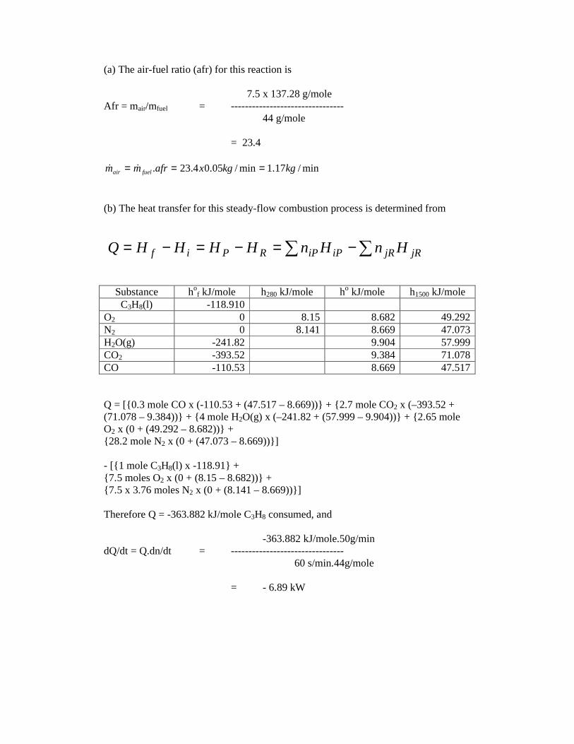
(a) The air-fuel ratio (afr) for this reaction is
7.5 x 137.28 g/mole Afr = mair/mfuel = --------------------------------
44 g/mole = 23.4
(b) The heat transfer for this steady-flow combustion process is determined from
Substance hof kJ/mole h280 kJ/mole ho kJ/mole h1500 kJ/mole
C3H8(l) -118.910 O2 0 8.15 8.682 49.292 N2 0 8.141 8.669 47.073 H2O(g) -241.82 9.904 57.999 CO2 -393.52 9.384 71.078 CO -110.53 8.669 47.517 Q = [{ 0.3 mole CO x (-110.53 + (47.517 – 8.669))} + { 2.7 mole CO2 x (–393.52 + (71.078 – 9.384))} + { 4 mole H2O(g) x (–241.82 + (57.999 – 9.904))} + {2.65 mole O2 x (0 + (49.292 – 8.682))} + { 28.2 mole N2 x (0 + (47.073 – 8.669))} ] - [{ 1 mole C3H8(l) x -118.91} + { 7.5 moles O2 x (0 + (8.15 – 8.682))} + { 7.5 x 3.76 moles N2 x (0 + (8.141 – 8.669))} ] Therefore Q = -363.882 kJ/mole C3H8 consumed, and
-363.882 kJ/mole.50g/min dQ/dt = Q.dn/dt = --------------------------------
60 s/min.44g/mole = - 6.89 kW
min/17.1min/05.04.23. kgkgxafrmm fuelair === ��
� �−=−=−= jRjRiPiPRPif HnHnHHHHQ
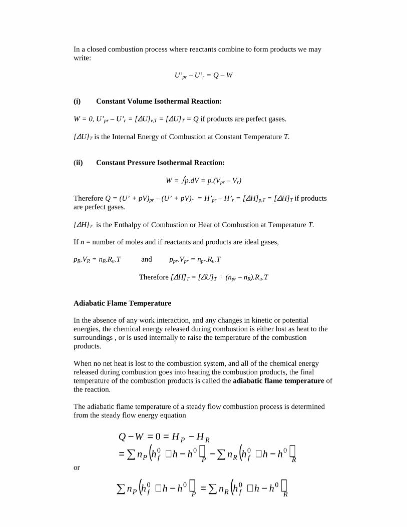
In a closed combustion process where reactants combine to form products we may write:
U’pr – U’ r = Q – W (i) Constant Volume Isothermal Reaction: W = 0, U’pr – U’ r = [∆U] v,T = [∆U] T = Q if products are perfect gases. [∆U] T is the Internal Energy of Combustion at Constant Temperature T. (ii) Constant Pressure Isothermal Reaction:
W = � p.dV = p.(Vpr – Vr)
Therefore Q = (U’ + pV)pr – (U’ + pV)r = H’pr – H’ r = [∆H] p,T = [∆H] T if products are perfect gases. [∆H] T is the Enthalpy of Combustion or Heat of Combustion at Temperature T. If n = number of moles and if reactants and products are ideal gases, pR.VR = nR.Ru.T and ppr.Vpr = npr.Ru.T
Therefore [∆H] T = [∆U] T + (npr – nR).Ru.T Adiabatic Flame Temperature In the absence of any work interaction, and any changes in kinetic or potential energies, the chemical energy released during combustion is either lost as heat to the surroundings , or is used internally to raise the temperature of the combustion products. When no net heat is lost to the combustion system, and all of the chemical energy released during combustion goes into heating the combustion products, the final temperature of the combustion products is called the adiabatic flame temperature of the reaction. The adiabatic flame temperature of a steady flow combustion process is determined from the steady flow energy equation
or
( ) ( )� � −+−−+=
−==−
RfRPfP
RP
hhhnhhhn
HHWQ0000
0
( ) ( )� � −+=−+RfRPfP hhhnhhhn 0000

Example: Liquid octane (C8H18) enters the combustion chamber of a gas turbine steadily at 1 atm and 25 oC, and it is burned with air which enters the combustion chamber at the same state. Disregarding any changes in kinetic and potential energies, determine the adiabatic flame temperature for (a) complete combustion with 100% theoretical air, (b) complete combustion for 400% theoretical air at initial temperature 400 oC. (a) The balanced equation for the combustion process is C8H18 + 25/2(O2 + 3.76N2) → 8CO2 + 9H2O + 47N2 The adiabatic flame temperature relation involving the constituent enthalpies is just
The heat of reaction for octane was calculated earlier as ∆hr = -5 512.18 kJ/mole octane reacted. As the initial state of the reactants is at the standard reference state, the sensible enthalpy of the reactants relative to the standard reference state is just zero. Therefore
This leads to the equation
(8 mole CO2).(hTa(CO2) – h0
298(CO2)) + (9 mole H2O).( hTa(H2O) – h0
298(H2O)) + (47 mole N2).( hTa(N2) – h0
298(N2)) = 5512.18 kJ This reduces to 8hTa(CO2) + 9hTa(H2O) + 47hTa(N2) = 5646.081 kJ
( ) ( )( ) ( )
( ) ( )��
� � ��
� �
� �
−−−+∆=
���
����
�−��
�
����
�+∆=
−−−+∆=
=−+−−+
15.29815.298
)()(
0)()(
21
15.29815.298
00
0000
TiCnTaCnh
dTCndTCnh
hTihnhTahnh
hTihhnhTahhn
pRpPr
R
Ti
pRP
Ta
pPr
RRPpr
RfRPfP
( )( )�
�
=∆−=−
=−+∆
kJhhTahn
hTahnh
rPP
Ppr
18.5512)(
0)(
0
0

This equation has to be solved iteratively. We make an initial guess based on the ideal gas law and the fact that most of the product is nitrogen. The enthalpy per mole of product is 5646.081 kJ/64 = 88.2 kJ/mole product. This corresponds to a temperature of 2650 K for N2, 2100 K for H2O, and 1800 K for CO2. Because most of the product is N2, we guess that the adiabatic flame temperature is around 2400 K. At this temperature 8h2400(CO2) + 9h2400(H2O) + 47h2400(N2) = 5660.828 kJ which is marginally larger than the actual value. If we guess Ta = 2350K, 8h2350(CO2) + 9h2350(H2O) + 47h2350(N2) = 5526.654 kJ This is significantly lower than the actual value. Linearly interpolating between these two enthalpies produces an adiabatic flame temperature Ta = 2394.5 K. (b) The balanced equation is C8H18 + 50(O2 + 3.76N2) → 8CO2 + 9H2O + 75/2O2 + 188N2 The adiabatic flame temperature equation is
This leads to the equation [(8 mole CO2).( hTa(CO2) – h0
298(CO2)) + (9 mole H2O).( hTa(H2O) – h0
298(H2O)) + (37.5 mole O2).( hTa(O2) – h0
298(O2)) + (188 mole N2).( hTa(N2) – h0
298(N2)) ] - [(50mole O2).( hTa(O2) – h0
298(O2)) + (188 mole N2).( hTa(N2) – h0
298(N2))] = 5512.18 kJ
This reduces to the equation 8hTa(CO2) + 9hTa(H2O) + 37.5hTa(O2) + 188hTa(N2) = 8314.61 kJ As before, we guess the adiabatic flame temperature. The enthalpy per product mole is 34.287 kJ/mole of product formed. This corresponds to a temperature of approx. 1126 K for N2, 1083 K for O2, 841 K for CO2, and 961 K for H2O. Therefore we guess an adiabatic flame temperature Ta = 1100 K. The above equation then gives
( ) ( )( ) ( )� �
� �
−−−+∆=
=−+−−+
RRPpr
RfRPfP
hTihnhTahnh
hTihhnhTahhn
00
0000
)()(
0)()(

8h1100(CO2) + 9h1100(H2O) + 37.5h1100(O2) + 188h1100(N2) = 8339.5 kJ This is marginally too large. If we assume Ta = 1080 K, then 8h1080(CO2) + 9h1080(H2O) + 37.5h1080(O2) + 188h1080(N2) = 8171.76 kJ Interpolating between the above enthalpies produces Ta = 1097 K. The true adiabatic flame temperature is less than that predicted in these examples. This is because at these high temperatures, the products are dissociative. At these high temperatures, there exists other intermediate species, and they serve to reduce the true adiabatic flame temperature. The adiabatic flame temperature calculated using only stable products (as in the examples) is known as the adiabatic frozen flame temperature.

City University
School of Engineer ing
Mechanical Engineer ing and Aeronautics
Par t 2 Applied Thermodynamics: Tutor ial 2
Where not otherwise specified assume the following: Composition of Air: By Volume By Mass Oxygen 21% 23.3% Nitrogen 79% 76.7% Ru = 8.3143 J/mole K, Rair = 287 J/kg K, Relative Atomic Masses: O = 16, N = 14, C = 12, S = 32 1. The composition by volume of a gaseous fuel is H2 14%, CO 24%, CO2 5%, O2
1%, N2 55%. Find the volume of air required for complete combustion of 1 m3 of this gas, and the composition by volume of the "dry" products of combustion.
2. Calculate the stoichiometric air-fuel ratio for the complete combustion of octane
(C8H18). 3. One kilogram of petrol (Octane C8H18) is burned with 20% excess air. Find the
percentage analysis i) by mass ii) by volume of the products of combustion, iii) by volume of the dry products of combustion.
4. A sample of coal has a composition by mass of Carbon 71.6%, Hydrogen 5.3%,
Oxygen 12.8%, Nitrogen 7.1%, Sulphur 1.2%, Ash (incombustible) 2.0%. Calculate the stoichiometric air supply for the complete combustion of the coal. Find also the gravimetric analysis of the flue gas when the coal is burned with 50% excess air.
5. A 4-stroke 4-cylinder petrol engine having a bore of 0.0635 m and a stroke of
0.0762 m was tested at a speed of 2500 rpm. The analysis of the dry exhaust products by volume was found to be 6.36% CO2, 11.34% CO, and 82.3% N2. There was no unburnt hydrogen or carbon in the exhaust. The fuel used was a hydrocarbon and the consumption was 5.5 kg/hr. Mixture entered the cylinders at a pressure of 101.3 kPa and a temperature of 15.5 oC. Determine: i) the percentages of carbon and hydrogen in the fuel by mass.
ii) the air fuel ratio by mass. ii i) the volumetric efficiency of the engine, neglecting the presence of the petrol
vapour. Take Rair = 286.5 J/kg K.
Mass flow rate of air through engine
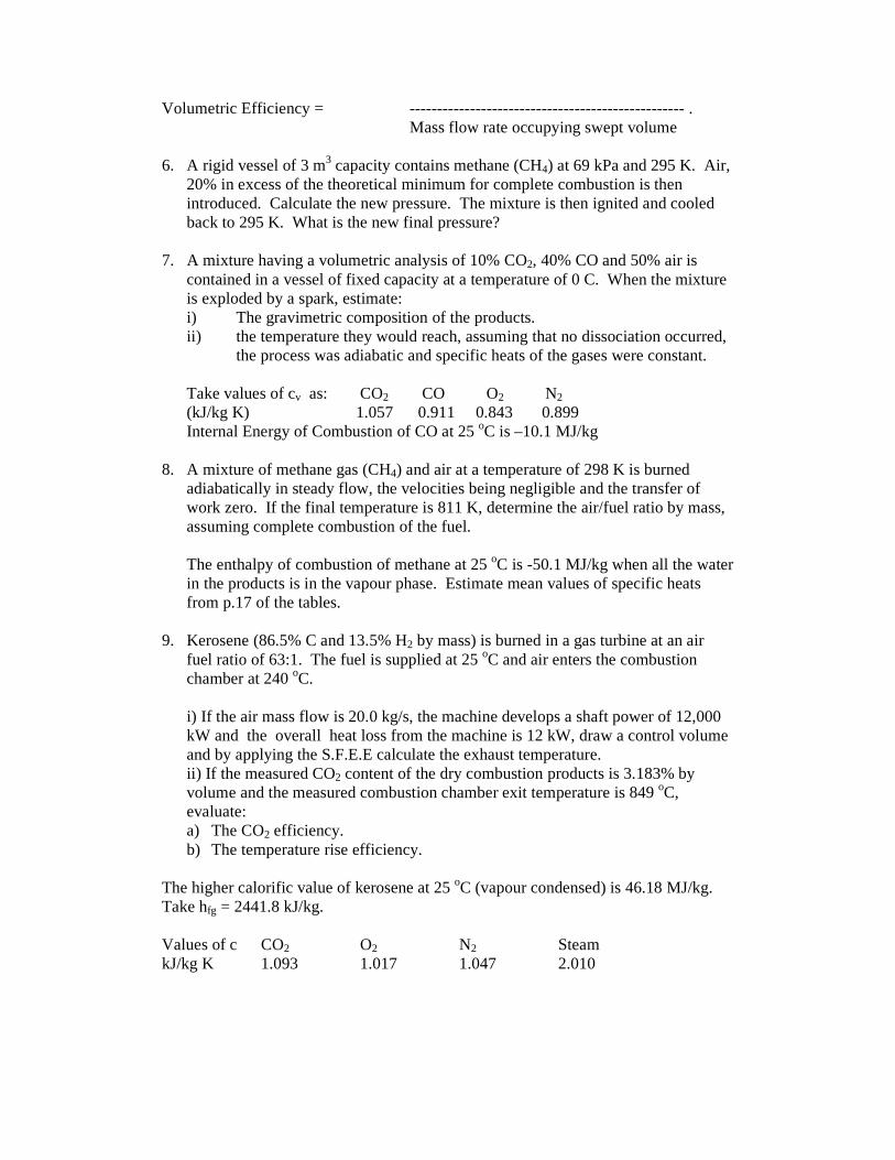
Volumetric Efficiency = -------------------------------------------------- . Mass flow rate occupying swept volume 6. A rigid vessel of 3 m3 capacity contains methane (CH4) at 69 kPa and 295 K. Air,
20% in excess of the theoretical minimum for complete combustion is then introduced. Calculate the new pressure. The mixture is then ignited and cooled back to 295 K. What is the new final pressure?
7. A mixture having a volumetric analysis of 10% CO2, 40% CO and 50% air is
contained in a vessel of fixed capacity at a temperature of 0 C. When the mixture is exploded by a spark, estimate: i) The gravimetric composition of the products. ii) the temperature they would reach, assuming that no dissociation occurred,
the process was adiabatic and specific heats of the gases were constant. Take values of cv as: CO2 CO O2 N2 (kJ/kg K) 1.057 0.911 0.843 0.899 Internal Energy of Combustion of CO at 25 oC is –10.1 MJ/kg
8. A mixture of methane gas (CH4) and air at a temperature of 298 K is burned adiabatically in steady flow, the velocities being negligible and the transfer of work zero. If the final temperature is 811 K, determine the air/fuel ratio by mass, assuming complete combustion of the fuel.
The enthalpy of combustion of methane at 25 oC is -50.1 MJ/kg when all the water in the products is in the vapour phase. Estimate mean values of specific heats from p.17 of the tables.
9. Kerosene (86.5% C and 13.5% H2 by mass) is burned in a gas turbine at an air
fuel ratio of 63:1. The fuel is supplied at 25 oC and air enters the combustion chamber at 240 oC.
i) If the air mass flow is 20.0 kg/s, the machine develops a shaft power of 12,000 kW and the overall heat loss from the machine is 12 kW, draw a control volume and by applying the S.F.E.E calculate the exhaust temperature. ii) If the measured CO2 content of the dry combustion products is 3.183% by volume and the measured combustion chamber exit temperature is 849 oC, evaluate: a) The CO2 efficiency. b) The temperature rise efficiency.
The higher calorific value of kerosene at 25 oC (vapour condensed) is 46.18 MJ/kg. Take hfg = 2441.8 kJ/kg. Values of c CO2 O2 N2 Steam kJ/kg K 1.093 1.017 1.047 2.010