Mechanical Efficiency Gearing - Gear TechnologyIntroduction Mechanical efficiency is an important...
10
D. Yu N. Beachley University of Wisconsin Madison, Wisc.onsin Mechanical Efficiency 0 1 £ Differential Gearing lltustration cou~te5yof Bred Foote Gear Works. Inc. Cicero, It
Transcript of Mechanical Efficiency Gearing - Gear TechnologyIntroduction Mechanical efficiency is an important...

D. YuN. Beachley
University of WisconsinMadison, Wisc.onsin
Mechanical Efficiency 01£Differential Gearing
lltustration cou~te5yofBred Foote Gear Works. Inc.
Cicero, It
IntroductionMechanical efficiency is an important index of gearing,
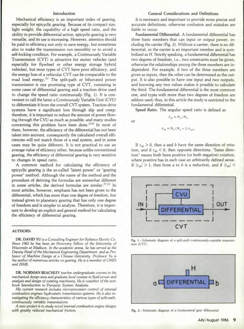
especially for epicyclic gearing. Because of its compact size,light weight, the capability of a high speed ratio, and theability to provide differential action, epicyclic gearing is veryversatile, and its use is increasing. However, attention shouldbe paid to effieiency not only to save energy, but sometimesalso to make the transmission run smoothly or to avoid asel:f-locking condition. For example, a Continuously VariableTransmission (CVT) is attractive for motor vehicles (andespecially for flywheel or other energy storage hybridvehicles), but most types of CVT have poor efficiency, andthe energy loss of a vehicular CVT can be comparable to theroad load energy. (1) The split-path or bifurcated powertransmission is One promising type of CVT, consisting insome cases of diffe.Jlential gearing and a traction drive usedto change the speed ratio continuously (Fig.. 1). It is con-venient to caU the latter a Continuously Variable Unit (CVU)to differentiate it from the overall CVT system. Traction drivesystems have a significant loss through slip and creep:therefore, it is important to reduce the amount of power flow-ing through the CVUas much as possible; and many studiesconcerning this problem have been done.l2-6) In most ofthem, however, the efficiency of the differential has net beentaken into account, consequently the calculated overall effi-ciencies will not match those of a real system, and in somecases may be quite different. It is not practical to use anaverage value of efficiency either, because unlike conventionalgearing, the effidency of differential gearing is very sensitiveto changes in speed ratio.
A common method for calculating the efficiency ofepicyclic gearing is the so-called "latent power" or "gearingpower" method. Although the name of the method and theprocedure ·0£ deriving the formulas are somewhat differentin. some articles, the derived formulas are similar. (7-11) Inmost articles, however, emphasis has not been given to thedifferential,. which has more than one degree of freedom, butinstead given to. planetary gearing that has only one degreeof freedom and is simpler to analyze. Therefore, it is impor-tant to develop an explicit and general method for calculatingtheeHidency of differential gearing.
AlTfHORS:
DR. DAVID YU is a Consulting Engineer for Reliance Electric Co.Since 1982 he has been an Honorary Fellow of the Uniuersity ofWisconsin at Madison. In the academic arena, he has seroed as theDeputy Head of the MechanicnI Engineering Depanmen.t, and as Pro-fessor of Machine Design at a Chinese University. Professor Yu isthe author of numerous artic1£s on gearing. He is a member of CMESand ISME.
DR. NORMAN BEACHLEY teaches undergraduate courses in themechanical'design area and' graduate level courses in flu id power andanalys.i.sand design of rotating machinery. He is coauthor of the text-book Introduction to Dynamic System Analysis.
His curren: research includes microprocessor control of internalcombustion engines! hydrostatic transmission systems. He is also in-uestigating theefficienqj chaTacteristks of various types of split-path,continuously uan'able transmissions.
Anew project is to study nouel internal combustion engine designswith greatly reduced mechanical friction,
General Considerations and DefinitionsIt is necessary and important. to provide some precise and
accurate definitions, otherwise confusion and mistakes areliable to occur.
fundamental Diff:erenHal. A fundamental differential hasthree basic members that can input or output power, in-cluding the carrier (Fig..2). Without a carrier, there is no dif-ferentia], so the carrier is an important member and is sym-bolizedas H. Strictly speaking, a fundamental differential hastwo degrees of freedom, i.e., two constraints must be given,otherwise the relationships among the three members are in-dependent. For example, if two or the three members aregiven as inputs, then the other can be determined as the out-put. It is also possible to. have one input and two outputs,and knowing any two values makes it possible to calculatethe third. The fundamental differential is the most commonone, and types with more than two degrees of freedom areseldom used; thus, in this article the study is restricted to thefundamental differential.
Speed Ratio. The angular speed ratio is defined as
or
If rab > 0, then a and b have the same direction of rota-tion, and if rab < 0, then opposite directions. "Same direc-tion" means both have positive (or both negative) rotation,where positive has in each case an arbitrarily defined sense.If ITabl > 1, then from a to b is a reductio.n,and if Ir~bl <
,-------,I I J' II t
CVU IIN J I OUT;..I 1DIFFERENTIALJJ--";'-': ----i!.~
L JCVT
fig. 1- Schematic diagram of a split-path ccntinuously-varlable transmis-sion (C\IT)
b
fig . .2- Schematic diagram 0.£ a fundamental gear differential
July IAugust 11986 9

than. is usually done. The basic ratio of a differential shouldexpress the specific features of the differential gearing andbe convenient for use.
There is only one speed ratio that can not amy be relatedto the size, but also provide the basic characteristics of a dif-ferential gearing. It is to be named the basic speed ratio Ro'
Rp =r~h
(Note, however, that the reciprocal ~a could be used asalternative if so desired.)
The relative speed ratio of a and b to H is based on con-sidering H as relatively fixed..It, therefore, can be determinedin the same manner as that of a conventional gear train, andthe relationships of teeth or diameters can be used.
The basic speed ratio can be calculated as
Fig. 3 - Three examples of the 2K - H( -) type of differential
Fig. 4! - Three examples of the 2K - H( +) type of differential
1, then from a to b is a speed-up or "overdrive". We definea high-speed ratio as occurring when either the absolute valueof a.reduction speed ratio is very large or the absolute valueof an overdrive speed ratio is very small. For example, bothIr"bl = IN,/Nbl = 1000 and Irbal = INblNQI = 111000 areconsidered as high speed ratios, and the lowest possible speedratio is therefore Ir] = 1. ..
If the speed ratio is relative to a third member, the relativespeed ratio should be used, and a superscript should be addedto the symbol with two subscripts. For example, the relativespeed ratio of a and b to H is defined as,
(La)
In the same way,
(Ib)
(Ic)
Thus we can get,Nq-Nh Na-Nb~~~ + ~lNb-Nh Nh-Nb
I
(231)
(2b)
r*. +r~b (2c)Expressions (2) are the fundamental kinematic relations of
a differential. from which other more complex formulas canbe derived.
Basic Speed Ratio. In manyartlcles.P: 5, 6, 10) the term"basic ratio of a differential" has been used, but for the pur-pose of this article, we will define the term more specifically
'J 0 Gear Technol'ogy
where:
R -rh =t }\P Zv,Zb' ....Q - .b - - f -z-~-,-z-· -, --
Q cJ • '. , •
(3)
numbers of teeth of the driving gearsfrom a to b,numbers of teeth of the driven gearsfrom a to h.
p = number of pairs of external gearing froma to b.
Bask Types of Epicyclic Gearing. A central gear K is de-fined as one whose axis continuously coincides with the com-mon central axis of the differential.
There are two main types of epicyclic differential: 2K-H(-) as shown in Fig..3, and 2K - H( +) as shown in Fig.4. 2K means two central gears, and the single H means onecarrier with planet gears. The '+' denotes Ro > 0, and '-'

b
~>o( b 1
Fig. 5 -The KHV type of differerltial 1i18.6-Chang in power flow directions that may occur wh n speed ratios are varied (wilh in~ndentconnections for the three differentIal elements)
means Ro < O. As shown in Fig. S. a [,elaHvely new type ofdifferentia] is theKHV, c,onsisting of only one central gear,one' camel'. and an equal angular velocity mechanism V,where V has, the same angular velocity as the planet gear g.~t is oompact in structure, light in weight, and with optimumdesign 'techniques, can often provide a higher efficiency.(12l[t is, 'thereJol'e, a. very PJ10mising type of gearing for someapplications. Since thel'e is only one pair ,of internal gears,the basic ratio Ro is positive. Some characteristics of theKHV typear,e similar to those of a 2K - H( +) type. Sincethe three basic membersofa KHV are b, H, and g (or V),aU. the previous and following 'equations are valid for it Ifg is substituted for a.
Efficiency. Power equals the product ,of torque and angularvelocity. or the product of Iorce and linear velocity.
We deflne input power Pin as pos:itive,.and both t.he out-put power Pout and the frictional. power Pf as negative.
Conventionally, ,efficiency is a positive value, therefore,sometimes a minus sign or absolute value, symbol must beused in the efficiency formulas, such as:
and
(4b)
Power Lost in. FrictionIf power's lost in friction,. simply called frictional power,
can be evaluated, it is easy to calculate the efficiency. Theprinciple adopted here is the concept of relative motion, thesame method as used for dealing with the kinematicrelationships.
Frictional power isa .function of ItoUlueand relative angularvelocity. Let us observe two systems. a dlfferential and a dif~ferential with its earsier H assumed relatively fixed. Theangular velocities of the latter sys~em are Na-Nh• Nf,-Nil, Ng-Nh• Nil-Nfl .... But the relative angular velodtyof any two members, for example of " and 8 (Nil - Nil) -(N, - N,,), Na - Ng• is the same as, that in the formersystem, so it is apparent that the two 'System provide thesame relativeangular velocities between each pair of meshed
gears. Because torque is independent of motion, the torqueof 'each element is not affected by whether or not H is rela-tiveJy fixed. ConsequenUy,a. useful conclusion can be drawn:the frictional power Pi of a dlfferential can be calculated inall cases byassuming the carrier H to be relatively fixed.
It is ,convenient to use the concept of latent power. WithH relatively fixed, we define
~= Ta(N. -Nh) (5)and
p;,=Tb(Nb-Nh) (6)There exist two possibilities. The first is that ,~is the drivingmember (input) and b is the driven member (output)1 whenHis relativeJy fixed. i.e.. pZ> 0 and pg < 0; where P; and
11 Ginger COurl,. lEast Amherst"New Yonk. 14051 • (716) 68&6982
Exclusive U.S.A distributo.r ,for the' Okamo,toSHG~360.400, 600 G&aF Grinders
IDesign.ed to meet the r,equirements for IPllecision,eoonomical grinding ,of ~ur and helical' ,gears, .....
For ,aircraft, automotive and machinery applica-tions.
Visit us at IBooth #6279, "986 I'MTS
OReLE A-114 ON READER' IREPLYCARD July IAugust 198611
-------- -- -
11 symbolize the powers of a and b when H is assumed tobe relatively fixed, Strictly speaking, they are not real powers.but since they have the same dimensions as power it is con-venient to refer to them as latent powers. Applying equa-tion (4) to the case of H relatively fixed.
h . IPfl (7)lIoh=l- ~
a
orh _ I
'lab- I+PfIPZ
The choice between equations (7) and (8) depends on whetherpi,; or n is available. Then.
IPf 1= (J -11:0)P.; '" (1- 1/~b) Ta (N. -Nh)
(S)
(9)
orIPfl == (l -7J~b) Pilll~b = (I - 1/~b) To (No -Nh) 11/~b (10)
where the superscript h means that His relatively fixed. andthe subscriptab denotes the power flow is from a to b.
The relationship between torques can be obtained asfollows:
(ll)so - 1/Zb(Na -Nh)
Nb-Nh (12)
The second possibility is that b is input and a is outputwhen H is assumed to be relatively fixed. i.e., fit > o andPa < O. In this case, .
1/io=J-IPJI/Pg (13)or
(14)
Then
or(16)
For the torque relationship,
or
(17)
(18)
In the same way, expressions of 'I/~hl '1t., 1jZh. and l1~bcould be derived, but only 'IJ~b 01' 'lJtR can be determined ina direct manner. As shown in the foregoing, one of these twomust be used to obtain a solution. This is the reason thatwe define either r::b or t1:Q as the basic speed ratio RD·
When the carrier His relatively fixed, certain features of3. differential are similar to those of conventional gearing.Thus, formulasfrom(7. 8lor relevant handbook dataavailable for conventional gearing can be used to' calculate
h . h1'/ab or 1'Iba'
The only remaining question is: when H is assumedrelatively fixed, which one of the two eHici.endes should beused, i.e., is a or b the input?
LetSa ;.P'j,IP" = T" (No -Nh) I TaN. ;:;;1- NhIN"s,=piIP/J"" TdNb -Nh) I TbNb ""I-NhINb
(19')(20)
where 5 is the ratio of the power assuming the carrier Hrelatively fixed to the actual power.
Usually the speed ratios Nf,IN" and NhIN" are known. Ifthe sign of either Fa or .P" is known, then by means of equa-tions (19) or (20) the sign of P,; or PI: can be determined.When P.i > Oor P6 < 0, then l1~b and equatlons (7..12)should be used. When PI: > 0 or ~ < 0, 1/g" and equations(13-18) should be used. Thus Pf will be obtained.
Efficiency of the Differential!After Pf is available and if Pin or Pout is known .. thenthe
Nomenclature
K = ratio of CVU output power to input power of totalsystem
Ko= ratio of CVU output power to input power of totalsystem with friction assumed zero
N = rotational speedP = power
pi,: = latent power of member aPf = Irictional power loss in differential
P"" = frictional power less in CVUPin = input power
po.ut = output powerr = angular speed ratio
rab = angular speed ratio, NalNb~b = relative speed ratio (Na - Nh)!(Nb - Nil)
R = relative speed ratio of members 3 and 1 to member2, (N3 - N2)/(N1 - N2)
l' 2' Gear Techno'iogy
Ro = basic speed ratio of a differential, ~b orrtgS = ratio of power assuming H relatively fixed to actual
powerT = torqueV = speed ratio of CVUZ = number 0.£ teeth on a gear'TI'=efficiency
1'/~" = efficiency f:rom a to b, assuming H relatively fixed'TId = efficiency of differential
110" = overall efficiency'l/v = efficiency of CVU
Subscripts and Superscriptsa = member a of a differentialb = member boE a differential.g = planet gear g ofa differentialh = carrier H of a. differential

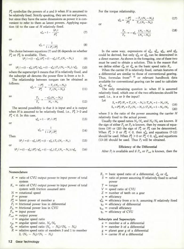
Fig. 7- Power input coupling to a differential
,efficiency of the differenfial can be calculated by means ofequation (4). However, we should first determine which ofthe three members (a, b, and H) is or are the input andoutput.
The torque equilibrium requirement is valid whether fric-tion is omitted or is taken into account (since the basic dif-f.erential. has no torque reaction to ground) is:
T, + Tb + Th=O (21)
Using equation (21) in combine tion with equations (12) or(l.8) allows two equations related to torques to be obtained,so the relationship between any two torques can bedetermined.
Power is the product of torque and angular velocity,'PQ;;;;;; Tu"Na• Po = Tb"Nb• Ph;;;;;; Th .Nh (22)
Therefore, the relationship between each two powers can alsobe calculated ..
If the sign. of one of the three powers is given, for exam-ple, Pa < 0 (i.e., a is output), the direction of the other twocan be obtained through equation (22). If, for example, PI,< 0 and Ph. > 0 (i.e., b is another output and H is input) thedifferential efficiency is obtained from equation (4) as
Ph- IP/il'/d=
Phor
IPgl+ IPbl'1d= --';.........-",:"",
Ph
However, it is not as simple as the case of planetary gear-ing, which has only one degree of freedom, For example, ifb is fixedand a is output, then H must always be the input
independent of speed ratio, and vice versa.Differential gearing has two degrees of freedom. Two of
the three members can be input and the other output. andvice versa, so there are six different possible combinations.Moreover, these relationships do not always remain Ithe samethroughout all the speed ratios needed. For example, if ~b
= -1.7 and PlJ < 0 (a is output) are given, then whenN/N" - -0.03 we find PtiPa - -59 ..6 and Pll/Pa =57 ..5, Le., b is input and H is output (Fig. 6a). When N/N"= 0.,05; however, we find PtiPa = 53.S and PhlPlJ ""
-55.9, i.e., b becomes output and H turns into input (Fig.6b), Therefore, when powers are connected separately to thethree members (Fig, 6) ,care must be taken to determinewhether the power signs will change during the speed ratiorange being used. If they do change, it is difficult to arrangethe power connection of the differential Consequently, it isimpossible to get the general formulas available for all speedratios, For example, in his article "Power Flow and Loss inDifferential. Mechanisms", no] Macmillan has derived six
. I (f' -' c - f· I Althc gh~. ·t ful the cangenera e,r IClency ormwas. _ ou' qu].e use_ '._, ._ y _only be valid for planetary gearing, not for a differential, sincethey require one of the three members of an epicyclic gear-ing to be absolutely fixed and not just relatively fixed. Con-sequently, the gearing operates with only one degree offreedom, and strictly speaking, two of the six formulas withfixed carrier are equivalent to those ~forconventional gearing.
Split-Path Transmissions EfficiencyTo generate formulas that are valid for all speed ratios,
it is necessary to couple two of the differential memberstogether rather than to connect power to each elementseparately. It is most common to use the power input eoupl-ed type of system (Fig. 7), A useful transmission forautomobiles and other mechanical applications is the input-coupled scheme shown in Fig. 8, where the CVU is a con-tinuously variable speed ratio unit, such asa variable V-beltdrive, a Perbury traction drive or some similar device. n 3. 6)
If we do not indude the possibility of regenerative brak-ing, member 3 in Fig..S is always the output (PJ - pouJ andPi" is always the input. Depending on the system par.am.etersand the speeds of the three d.ifferential elements, therearethree possibilities: (a) PI > Oand Pz > 0., (Fi.g 831) (b) Pl. <o and P2 > 0, producing what is known as positi.ve powerrecirculation through the CVU (Fig 8b). and (c) 'P1> 0 andPz < 0, producing negative power recirculation (Figure Be).
In all three cases considered, the condition that power is
Fig. 8-An input-coupled split-path CVT showing the three power flow possibilities
(b) Ie).
P
P1>O P3=Pou,<O
10 )
jJlyjAugust 1986 13

]. rD-l. I
. ~. I-+--+_"""""iiI---+---t---tll'-+--I--I
4.0b:! 4 I
II---------ll-+-+--l 'I-........""""'t-l
'5.1
0-.~
1:-+-+--1
].
input at UP/n"and output as "Pour" remains unchanged, sothat the basic scheme of the transmission is the same. Theoverall. speed ratio of the transmission is r, defined as r =NoulNj" = NJ/Nt. The speed ratio of the CVU is V =N2lN1• Let R be the relative speed ratio of .3 and 1 and 2,
r-V1- V
thenV= (r-R) / (1- R) (23)
r;;;;;;R+(l-R)V (24)If the efficiency of the CVU is '1v and the power pass Lng
thf'ough the CvU at the differential side is P" = P2, thenwhen P" < 10, the loss in the CVU is
IPf,·1 == IP,.I (l -I),.)
and when P2 > 0, it becomesIPj,.1== IP, I(I - '1,.)111" (25b)
If the power loss through the diff·erential. is Pf, then the total[ass is
(25a)
(26a)
orPIOss/POUI =Pj/Poul +Pj,./Poul
The input power of the system isPin;;;;;; - (Paul +Pi; .. )
(26b)
(27a)or
(27b)
1,4 Gear Technology
The overall efficiency of the system, which is more impor-tant than that of either the differential or the CVU alone willbe
(28)
K is defined as the ratio of the input power 0·£ the CVUto the input power of the system. A positive Pu means thatpower passes from the CVU to the differential, and vice ver-sa, so that
when .K=P,./P", (29a)(29b)when K=P,./I),,/Prn
ExampleTo help clarify the foregoing, the following example is
given: t~e ~iffer,enti~ is chosen!o be a 2K. - H( -)ty~ asshown 1m Flg. 3a WIth Zb= 153, Z, = 90, so th<1t ~b .
-ZIIZ" = -153/90 = -1.7,
1. The conditions given are: a is the ouput and H is theCVUi i.e., a at 3, H at 2, and b at 1, Ro = rgb= -1.7,and r = N31Nt = N,/N" = -0.13.
2. V = N21Nl = NhlNb, and from equation (23), V =(-0.13+1.7)/(1+1.7)'= 0.581, and NhlN." = Vir =-4 ..47.
3. Sa = p';IPa = 1 - NhIN .. - 5.47 > O. Since a isoutput, i..e., Pa = Pout < 0, then ~ < 0, i.e., a is drivenwhen H is relatively fixed, Therefore, assuming 1)ia = 0.95and using equations (13)-(18), we get TbIT~= 1.789 andThIT" = - 2.789.
4. Fromequations (21) and (22), the power relationshipsare Pi/P; Cl -13.77, PhlPa = 12 ..48,. and PrlPa = 0.288 ..Since Pa < 0, then Pb > 0 and Ph < O. Therefore, in ,the dif~ferential b is the input, a and Har,e outputs.
5. Now usingequat:ion (4a), we get the efficiency of thedifferential, 'lJd = - (P~+Pb)/Pb = 97.9 percent
6. If the efficiency of the CVU is assumed to be '1u ==0.9, then From equation (25) we get IPft, l1'out 1 = IPh 1(1 -'1],) I IPout 1 = 12.48 (1 - 0.9)= 1.248, and from equation(26b) we obtain p/os'/Pout = 0.288 + 1.248 = 1.536.
7. The input power needed (equation (27b)) is Pir/Poul= -(1+1.536) = -2.536. The overall efficiency of thesystem can now be calculated as 'loa =- P0..1Pin' ....-1/( -2.536) = 39.4 percent.
Fig. 9-Power flow diagram of the example
p. >0In
Pou1 <0

Ag. 10- Computer flow chart a1culati11g program for the input-coupled cvr
8.. The portion. of the input power passing through theCVU is K= PulP';" = P'"IP"/(P';"IPout) = -4.92. Theminus sign means negative power recirculation ..
9. The power flow directions are shown in Fig. 9.
Types of ConnectionAn important and interesting feature should be pointed out:
there are six possible types of connection for the three basicmembers of each differ'ential characterized by its basic speedratio. Six. different designs are available which enlarges thepotential usage. for example, for a 2K - H(-) type with Ro= rUb -1.7, we have the following sixpossibilities as listed in Table 1:
1. If a is output and H is CVU (i.e., a at 3, H at 2, bat 1), then R. = r1:b .... -1.7 (as in the foregoing example).
2. If a is output and b is CVU (i.e., a at 3, Hat 1, bat2), then R =":11 1 - ~b = 2.7
3.. If H is output and a is CVU, (i.e., H at 3, aat .2, bat 1), then. R. = r1:b = lIrl:h = 11(1 - ,..ga), and ,.gil -= IIr!:b,R = 0 ..630.
4. If H is output and b is CVU (i.e., Hat 3., a at 1, bat 2). then R = ~hQ = lIr:h = 1I(1-~) = 0.37.
5. [f b is output and a is CVU (i.e., b at 3, a at 2. H at1), then R = ,.gil = 1 -,.g., 1 - 1Ir!& - 1.59.
6. If b is output and His CVU (i.e., bat 3", ,a at 1, Hat 2)', then R = ,..gR = lIr:b .... -0.59'.
Furthermore, if over 'the range of usage the type of con-nectioncan be changed, the design pessibillties will be in-creased still further. Theoretically, 36 different designs arepossible. provided that all three basic members can. inter-change positions. However. practical mechanisms for ac-complishing this may be quite ,complicat'ed. [f only two, ofthe three members are to interchange positions. there will benine combinations as listed in Table 1. and the mechanismsfor this will be much simpler(UJ . .For example, if band H caninterchange positions. over the range of usage, there will bethree combinations: l, U.and Ill. Ref,erring to Table 1; com-bination .I means that a isuncha~ged 35 the system output,but b and H interchange between the other two connections.The other eight combinations are similarly defined in Table1. Note further that tor any change in the basic speed ratio(i.e., changes in numbers of gear teeth),another six types andnine combinations can be obtained.
From the numerous possibilitiee, an optimum choice canbe made to s.atisfy particular requirements. The details havebeen introduced in another article. (13)
Computer-.AJded Design.To avoid arduous manual calculations, it is better to design
AGMIA 1110.Nomencla.ture of GearTooth Faililiure M,odes
AGIMA 110 Is the deUnltlve document ongear tooth wear and failure.
WeU Illustrated,. with ,excellentphotographs of distressed geW'
teeth, It provildes descrlpIlol'lsof ti'le faHulres, their causes"
and suggested remedies.
This stand'ard has been widell)!',,"",""'"'''' ...,. 1 cited In technlcall literature and
......... T............ ether g:eer standards. It ilsIndlspensllble'to the :serlous
g.eaf engineer.Price: I d$28, AGMIA 110 - Intematlo.nal'ly recogn ze as
the authorJ,taUve standard on this sublect
Send order with check 10:
Publica lion Sales (91Amer'ican Gear Manulacturers Assn. -.. '
1500 King Street. Suite 201 _ ~. ' 'I.Alexandria. VA 22314
(703) 684·0211Telephone credit card orders accepted
.kJ1y j.August 1986 15:

Fig..II-Required speed ratio relationships of the input-coupled CVT withRo = -1.7, for the six ways of using the differentia]
a general computer program to solve the problem. Two pro-blems have been developed, the first one for calculation andthe second for plotting curves. The flow chart of thecalculating program is given in Fig. 10. Subroutines PAl andPAZare used to calculate torque and power relationships.Subroutine EF is designed to determine efficiency.
The input data are: (1) the basic speed ratio Ro' whichrepresents the features of the differential gearing, (2) the rangeof speed ratios of the system, i.e., the maximum andminimum speed ratios, (3) the efficiency of the gearing withH assumed relatively fixedand (4) theeffidency of the CVU.Each basic speed ratio (i.e., each specific differential) can pro-vide six different split path CVT designs, and useful curvescan be plotted for each.
For example, if the basic speed ratio R; = -1.70 and itis a 2K - H( -} type, then the relationship between V =N2/ Nl and r = N3/N1 is as given in Fig. 11. If 1J~b = lIg"0.95 and lIv = 0.90, the overall efficiency characteristics areas given in Fig. 12, and the fraction of power through theCVU as given by Fig. 13. The labeling from 1 to 60f thed:ifferent curves is the same as used earlier. With the frictionloss assumed to be zero, as is normally the case in other CVTanalysis articles, the fraction of power through the CVU isgiven the symbol Ko' and the curves of Ko are shown in Fig.14. A comparison of Figs. 13 and 14 shows that Ko is quitedifferent from K. Fig .. 12 also shows that the overall effici-ency is often far from 100 percent. It is concluded, therefore,that frictional losses must be included for realistic analysis.From the data and curves obtained, and the CVTcharacteristics needed, it may be possible to determine a better
16 Gear Technology
Fig. 12- Efficiencycharacteristics of the input-coupled cvr for the six waysof using the differential (Ra ~ 1.7. lIu ~ 0.90,. 'I~b = 'It. = 0.95)
Fig. 13 - Fraction of power through the CVU (29) with friction losses takeninto account
design. For example, if N31Nl = O.S to 2.0 is used most ofthe time, curve 4 may be attractive, because it provides ahigher efficiency and a smaller power through the CVU.However, if the available range of V = N21 Nl is smaller,it may be better to choose curve 6, because V varies onlyfrom 0.69 to 1,66, although the efficiency in this case wouldbe lower.
SummaryBecause of its compact structure, small size, capability of
high speed ratios, and the differential action itself, differen-tial gearing has been often employed in modem machinery ..However, in many design analyses, an important index,mechanical efficiency, has been ignored. The assumption of
(continued on page 48)

MECHANICAL EfFICIENCYOF DIFfERENTIAL GEARING(continued from page Ip)
no friction loss certainly does not coincide with reality, andin some cases the analytical results with this assumption willlead to wrong conclusions. The method introduced in thisarticle for analyzing efficiency is simple, explicit, and ap-plicable to all differentials with two degrees of freedom.Although the example given was an input-coupled system,the principles and formulas are equally applicable to output-coupled systems.
It has been pointed out that a "basic speed ratio," giventhe symbol R; in this article, should be defined in a specificmanner, so that it will express the significant characteristicfeatures of the differential and be most useful for analysisand calculation.
The classification system of differential gearing used in thisarticle is different from conventional. systems such as thatgiven in the Gear Handbook. (14) This classification is con-sidered advantageous in emphasizing the significant dif-ferences of the various design possibilities.
The great number of design possibilities inherent in the useof differennal gearing has been pointed out, especially ifdesigns are employed that allow the basic members to inter-change positions over the range of operation. Computer-aideddesign can be of significant help in developing an optimumdesign from the numerous possibilities.A flow chart and sum-mary of an applicable computer program have beenpresented.
References1. BEACHLEY, N. H., et al., "Continuously-Variable Transmis-
sion Designs for Flywheel-Hybrid Automobiles," Proceedingsof the International Symposium on Gearing and PowerTransmissions, Tokyo, 1981, pp. 393-398.
Fig. 14- Fraction of power through the CVU for zero friction loss
-1.0 -0.5 0 0.5 1.0 1.5 2.0SPEED RATIO. r= N31 NI
48 Gear Techno~logy
2. WHITE, G., "Properties of Differential Transmissions," TheEngineer, Technical Contribution Section, July 28, 1967, pp.105-111.
3. WHITE, G., "A Two-Path Variable-Ratio Transmission withan Extended Range of Ratios," ASME Journal of Engineeringfor Industry,. Aug. 1977, pp. 656-661.
4. WHITE, G., "Compounded Two-Path Variable Ratio Transmis-sions With Coaxial Gear Trains," Mechanism and MachineTheory, Vol. 11, 1976, pp. 227-240 ..
5. MACM1LLAN, R. H., and DAVIES, P. S., "Analytical Studyof Systems for Bifurcated Power Transmission," Tournai ofMechanical Engineering Science. Vol. 7, No.1, 1965, pp 40-47.
6. STUBBS, P. W. R., 'The Development of a Perbury TractionTransmission for Motor Car Applications," ASME paper80-C2/DET-59, 1980.
7. KUDLYAVfZEV, V. H., Planetary Gearing (Russian) Machine-Building Publisher, 1966.
8. YU, DAVID, "Problems Arising in the Calculation of GearingEfficiency," Liaoning Machine (Chinese), No.2, 1980, pp.·33-42.
9. MACMILLAN, R. H., "Epieylic Gear Efficiencies," TheEngineer, Dec. 23, 1949, pp. 727-728.
10. MACMILLAN, R. H.,. "Power Flow and Loss in DifferentialMechanisms," Journal of Mechanic.al Engineering Science, VoL3, No.1, 1961, pp. 37-41.
11. MOROZUMI MUNEHARU, "The Efficiency and the Designof Modified Internal Gearing," Mechanical Researches(Japanese), No.5, 1970, PI'. 720-726.
12. YU, DAVID,. "The Optimizing Programming Design of theKHV Planetary Gear Driving," Proceedings of the InternationalSymposium on Gearing and Power Transmissions, Tokyo,1981, pp. 295-299.
13. YU, DAVID, and BEACHLEY, N. H., "Alternative Split-PathTraction Drive Transmission Designs for Motor Vehicle Ap-plication," Proceedings, First International Sympos.ium onDesign and Synthesis, Tokyo, July 1984.
14. DUDLEY, D. W., et aI., Gear Handbook, McGraw-Hill, NewYork,1962.
This article WClS previously presented at the ASME De;;igl1Engineering TechnicalConference, October 1984. Paper No. 84-Det-102.
PROF.ITS ARE BEING MAD:E. . . by advertising in GEAR TEC:HNOLOGY,The Journal of Gear Manufacturing's classifiedadve.rtising section. Advertiise your specialty:
• Open time on speci'al or unusual machines• Unique capabiliities• Machine quality• Help wanted• Subcontract work
Your ad reachesover 5,000 potentiall customers.
Call! GEAR TECHNOLOGY for details.(312) 437~6604
CIRCLE A-30 ONi READER IREPlYCAIRO