Mechanical Design of a Trawl-Resistant Self …...Mechanical Design of a Trawl-Resistant...
65
Mechanical Design of a Trawl-Resistant Self-Mooring Autonomous Underwater Vehicle Taylor B. Wilson Thesis submitted to the Faculty of the Virginia Polytechnic Institute and State University in partial fulfillment of the requirements for the degree of Master of Science In Ocean Engineering Wayne L. Neu, Chair Daniel J. Stilwell Craig A. Woolsey December 8, 2015 Blacksburg, VA Keywords: Autonomous Underwater Vehicle, Self-Mooring, Trawl-Resistant, AUV, TRSMAUV
Transcript of Mechanical Design of a Trawl-Resistant Self …...Mechanical Design of a Trawl-Resistant...

Mechanical Design of a Trawl-Resistant Self-Mooring Autonomous Underwater
Vehicle
Taylor B. Wilson
Thesis submitted to the Faculty of the
Virginia Polytechnic Institute and State University
in partial fulfillment of the requirements for the degree of
Master of Science
In
Ocean Engineering
Wayne L. Neu, Chair
Daniel J. Stilwell
Craig A. Woolsey
December 8, 2015
Blacksburg, VA
Keywords: Autonomous Underwater Vehicle, Self-Mooring, Trawl-Resistant,
AUV, TRSMAUV
Mechanical Design of a Trawl-Resistant Self-Mooring Autonomous Underwater
Vehicle
Taylor B. Wilson
ABSTRACT
The Virginia Tech Trawl-Resistant Self-Mooring Autonomous Underwater Vehicle
(TRSMAUV) is designed to reside on the seafloor for extended periods of time. The
TRSMAUV shape allows for deployment in areas where trawl fisheries are conducted.
TRSMAUV is a two stage vehicle. The ingress vehicle is the delivery device, and it is
constructed from two symmetric halves. The top half contains the ingress vehicle propulsion
system and control surfaces. The bottom half is the trawl-resistant mooring package. A smaller
vehicle, the egress vehicle, is housed within the bottom ingress half and provides the guidance,
navigation and control algorithms for the TRSMAUV. This report covers the general design
elements of the TRSMAUV, the detail design of several prototypes, the results of the field trials,
and the next steps that will be taken to build the final vehicle.

iii
Acknowledgments
I would first like to thank the rest of the design team of the TRSMAUV project. This was a very
long and complicated project, and many graduate students made sizable contributions. Every
team member contributed ideas to parts of the process that may or may not have been within
their technical field. I also cannot thank Dr. Neu and Dr. Stilwell enough, they contributed
advice and ideas throughout every stage of the vehicles development. I would also like to extend
a thank you to the engineering team at the Naval Oceanographic Office. They provided a
significant amount of technical support and this project would not have been possible without
them.

iv
Contents
1 Introduction ............................................................................................................................. 1
1.1 Mission Profile ................................................................................................................. 2
1.2 Design Approach and Team Structure ............................................................................. 4
1.3 Thesis Layout ................................................................................................................... 5
2 Conceptual Design ................................................................................................................... 6
2.1 Egress Vehicle .................................................................................................................. 6
2.2 Ingress Vehicle ................................................................................................................. 7
2.2.1 Exterior Shape Design .............................................................................................. 8
2.2.2 Preliminary Hydrodynamic Analysis ........................................................................ 9
2.2.3 Overall Systems Layout .......................................................................................... 12
2.2.4 Egress Vehicle Release ........................................................................................... 17
3 Ingress Scale Model............................................................................................................... 20
3.1 Design Features .............................................................................................................. 20
3.2 Testing ............................................................................................................................ 21
4 Ingress Limited Prototype ..................................................................................................... 23
4.1 Shell ................................................................................................................................ 23
4.2 Separation ....................................................................................................................... 25
4.3 Mooring .......................................................................................................................... 25
4.4 General Assembly .......................................................................................................... 26
4.5 Field Test ........................................................................................................................ 27
5 Egress Vehicle ....................................................................................................................... 28
5.1 Nose Modifications ........................................................................................................ 29
5.2 Tube Modifications ........................................................................................................ 30
5.3 Field Testing ................................................................................................................... 31
6 Ingress Vehicle Prototype ...................................................................................................... 33
6.1 Stability .......................................................................................................................... 33
6.2 Propulsion....................................................................................................................... 35
6.3 Dynamic Pitch Stability ................................................................................................. 40
6.4 Buoyancy Control .......................................................................................................... 42
v
6.5 Separation ....................................................................................................................... 43
6.6 Pressure Vessels ............................................................................................................. 45
6.6.1 Tube Design ............................................................................................................ 46
6.6.2 Bulkhead Design ..................................................................................................... 50
6.6.3 Shaft and Seal Selection and Assembly .................................................................. 51
6.7 Shell ................................................................................................................................ 52
6.8 General Assembly .......................................................................................................... 54
7 Next Phase ............................................................................................................................. 55
8 References ............................................................................................................................. 56

vi
List of Figures
Figure 1.1: TRSMAUV in the initial deployment state .................................................................. 1
Figure 1.2: The eight different phases of the TRSMAUV mission profile .................................... 2
Figure 1.3: Schematic of mooring mission profile (not to scale) ................................................... 3
Figure 1.4 Egress vehicle ................................................................................................................ 4
Figure 2.1 Traditional trawl-resistant mooring manufactured by Mooring Systems, Inc [9] ......... 6
Figure 2.2 Virginia Tech Self-Mooring AUV shown without the false nose, which functions as a
mooring anchor ............................................................................................................................... 7
Figure 2.3 Hypothetical ingress vehicle [7] .................................................................................... 8
Figure 2.4 Exterior shell dimensions for the ingress vehicle ........................................................ 10
Figure 2.5 CFD results from the one-sided ingress vehicle [6] .................................................... 11
Figure 2.6 CFD results for double sided symmetric body [6] ...................................................... 11
Figure 2.7 Hypothetical air tube utilizing an internal spring to open bulkheads and initiate
flooding. ........................................................................................................................................ 13
Figure 2.8 Conceptual inboard (left) and outboard (right) propulsion system configurations. .... 14
Figure 2.9 Hypothetical separation mechanism [7] ...................................................................... 16
Figure 2.10 Conceptual descent options. ...................................................................................... 17
Figure 2.11 Mooring package top cap release [7]......................................................................... 18
Figure 2.12 Egress vehicle release [7] .......................................................................................... 18
Figure 2.13 Pneumatic release [7] ................................................................................................ 19
Figure 2.14 Pyrotechnic release [7] .............................................................................................. 19
Figure 3.1 TRSMAUV scale model in deployment configuration. .............................................. 20
Figure 3.2 The three descent and mooring configurations evaluated during the TRSMAUV scale
model tests. ................................................................................................................................... 21
Figure 3.3 Ingress vehicle orientation for trim and ballast calculations ....................................... 22
Figure 4.1 Limited prototype ingress vehicle being deployed in the Gulf of Mexico .................. 23
Figure 4.2 Top half shell ............................................................................................................... 24
Figure 4.3 Separation layout (S. Portner) ..................................................................................... 25
Figure 4.4 Limited prototype bottom frame ................................................................................. 26
Figure 4.5 Ingress limited prototype separation test ..................................................................... 27
Figure 4.6 Ingress limited prototype trawl resistance test ............................................................ 27
Figure 5.1 Field testing the egress vehicle in Claytor Lake, VA .................................................. 28
Figure 5.2 VT-SMAUV Nose ....................................................................................................... 29
Figure 5.3 Egress vehicle nose ...................................................................................................... 29
Figure 5.4 Egress vehicle nose shown in the configuration for independent field trials. ............. 30
Figure 5.5 Egress vehicle yaw steps mission (Euler angles) ........................................................ 31
Figure 5.6 Egress vehicle depth steps mission (Euler angles) ...................................................... 32
Figure 5.7 Egress vehicle depth steps mission (depth) ................................................................ 32
Figure 6.1 CFD simulation set up [6] ........................................................................................... 34
vii
Figure 6.2 Preliminary skeg (left) final skeg (right). .................................................................... 34
Figure 6.3 Skeg surface area required to produce zero net moment at various yaw angles of
attack [6] ....................................................................................................................................... 35
Figure 6.4 CAD models used for CFD analysis showing the inboard (left) and outboard (right)
propeller configurations. ............................................................................................................... 35
Figure 6.5 Flow velocity profile shown behind the vehicle and behind the motor pod. Note the
asymmetry in the flow field associated with the propeller positioned behind the vehicle [6]...... 36
Figure 6.6 Prototype ingress vehicle propeller. ABS (left) Nickel and Copper plated ABS (right)
....................................................................................................................................................... 38
Figure 6.7 FEA results on ABS propeller blade (psi) [6] ............................................................. 39
Figure 6.8 Ingress vehicle yaw command from one propeller at maximum thrust [6] ................. 39
Figure 6.9 Moments experienced by the ingress vehicle at nonzero pitching angles of attack .... 40
Figure 6.10 Righting moment generated by flaps when deflected at 15 degrees in both directions
[6] .................................................................................................................................................. 41
Figure 6.11 Elevator assembly ...................................................................................................... 41
Figure 6.12 Torque experienced by elevator shaft when the flap is at max deflection at various
angles of attack [6] ........................................................................................................................ 42
Figure 6.13 Prototype buoyancy tube ........................................................................................... 43
Figure 6.14 General decomposition of loading forces between the two halves ........................... 44
Figure 6.15 Separation assembly placement in the TRSMAUV ingress vehicle, electronic wire
cutters sever cable and differential buoyancy between the two vehicle halves causes separation.
....................................................................................................................................................... 44
Figure 6.16 Finite Element Analysis (FEA) results on ABS plastic alignment plate. .................. 45
Figure 6.17 Partially exploded view of one of the motor bottles used in the TRSMAUV ingress
vehicle. .......................................................................................................................................... 46
Figure 6.18 Dimensions and stress conventions of the tube stress analysis [8] ........................... 47
Figure 6.19 Battery bottle FEA simulation results ....................................................................... 49
Figure 6.20 Mesh element size selection. The stress on the y-axis was averaged from several
grid points selected at the tube center. .......................................................................................... 50
Figure 6.21 External linkage ......................................................................................................... 52
Figure 6.22 Ingress vehicle prototype shells................................................................................. 53
Figure 6.23 General layout for the ingress vehicle prototype ....................................................... 54
Figure 6.24 Ingress prototype ....................................................................................................... 55

viii
List of Tables
Table 2.1 OpenProp optimization results [6] ................................................................................ 14
Table 3.1 Weights and CG/CB locations for the ingress vehicle immediately prior to separation
[7] .................................................................................................................................................. 22
Table 5.1 Egress vehicle specifications ........................................................................................ 28
Table 6.1 Propulsion design specifications [6] ............................................................................. 38
Table 6.2 Stress analysis results for bottle designs (𝐹𝑜𝑆𝑐𝑟𝑢𝑠ℎ based on infinite tube calculations
and 𝐹𝑜𝑆𝑏𝑢𝑐𝑘𝑙𝑖𝑛𝑔 based on actual bottle lengths) ........................................................................ 48

ix
List of Abbreviations
AHRS: attitude, heading and reference system
AUV: autonomous underwater vehicle
CAD: computer assisted drawing
CB: center of buoyancy
CEP: circular error probable
CFD: computational fluid dynamics
CG: center of gravity
COTS: commercial off the shelf
CPU: central processing unit
FEA: finite element analysis
GPS: global positioning system
LED: light emitting diode
MATLAB: matrix laboratory (software)
RPM: rotations per minute
VT-SMAUV: Virginia Tech Self-Mooring autonomous underwater vehicle
TRSMAUV: Trawl-Resistant Self-Mooring autonomous underwater vehicle

1
1 Introduction
The Autonomous Systems and Controls Laboratory at Virginia Tech developed an Autonomous
Underwater Vehicle (AUV) that is capable of traveling to a location and anchoring itself on the
sea floor to collect data (the Virginia Tech Self-Mooring AUV). It is desirable to have such an
AUV capable of mooring itself in locations where commercial trawl fisheries occur. To achieve
this, the AUV must be both self-mooring and trawl-resistant. For an AUV to be trawl resistant
when moored, it must mimic the characteristics of other trawl-resistant bottom-mounted devices.
These devices are able to deflect trawls (e.g., trawl footropes, roller gear, bridles) without
sustaining damage. The Virginia Tech Trawl-Resistant Self-Mooring Autonomous Underwater
Vehicle (TRSMAUV) is designed for this purpose.
The TRSMAUV is a two stage vehicle. The ingress vehicle is the delivery device, and it is
constructed from two symmetric halves. The top half contains the ingress vehicle propulsion
system and control surfaces. The bottom half is the trawl-resistant mooring package. A smaller
egress vehicle is housed within the bottom ingress half and provides the guidance, navigation
and control functions for the TRSMAUV.
Figure 1.1: TRSMAUV in the initial deployment state
The TRSMAUV will navigate to a predetermined mooring location and execute a controlled
descent to the sea floor. Before the vehicle reaches the bottom, the two halves will separate and
the bottom half will settle to the sea floor in an inverted state to achieve a low-relief, trawl-
resistant profile. The vehicle is designed to deflect trawl cables at speeds < 4 knots. Design
criteria also specify that the TRSMAUV can remain moored for up to one year at depths < 500
m. Upon completion of the moored period, the egress vehicle is released from the TRSMAUV
bottom half and returns to a recovery location.

2
The egress vehicle design was based on the existing Virginia Tech Self-Mooring AUV (VT-
SMAUV). This paper details the design of the ingress vehicle, the construction of a prototype
ingress vehicle, the construction of the egress vehicle, and field testing of both vehicles.
1.1 Mission Profile
The TRSMAUV mission profile can be separated into eight different phases: 1) Ingress, 2)
Buoyancy Release, 3) Helical Descent, 4) Separation, 5) Landing, 6) Top Half Release, 7) Egress
Vehicle Release, and 8) Egress.
Figure 1.2: The eight different phases of the TRSMAUV mission profile
During the ingress phase the TRSMAUV is deployed and swims to a predetermined location.
The TRSMAUV has a range of < 50 nautical miles and can be deployed in areas where a head
current of < 0.5 m/s is present. The vehicle is designed to cruise at a speed of 2 m/s at a depth of
3 m. When the vehicle arrives at the designated surface location, buoyancy is released to alter
the vehicle’s buoyancy state. This release gives the vehicle a negative net buoyancy (roughly
10%) for the descent phase. The vehicle then begins a controlled helical descent to a depth <

3
500 m. As the vehicle nears the sea floor the two halves separate at a user-defined depth. The
two halves remain in a temporary state of attachment so that the bottom half is allowed to roll
over and descend in an inverted state. This allows the buoyant top half to act as a drogue for the
heavy bottom half. The bottom half will gently come to rest on the seafloor in this inverted state
to achieve the trawl-resistant profile. Once the bottom half settles to the sea floor, the disposable
top half is released and drifts away.
Figure 1.3: Schematic of mooring mission profile (not to scale)
Design parameters specify the TRSMAUV must land within a 200 m circular error probable
(CEP) of its last GPS fix even when subject to an unknown current with a magnitude < 0.25 m/s.
The final moored position will be within 800 m of the desired location (Fig. 1.3). The vehicle
can remain in its moored state for up to one year. The egress vehicle is released upon
completion of the data collection period, and autonomously navigates to the desired recovery
location for extraction.
4
1.2 Design Approach and Team Structure
The TRSMAUV is designed as a trawl-resistant mooring device for integration with the existing
Virginia Tech Self-Mooring AUV (VT-SMAUV) [5]. This integrated package required slight
modifications to the VT-SMAUV for use as an egress vehicle and the design of a new trawl-
resistant ingress vehicle. Designing the overall shape of the ingress vehicle was the first
challenge. This overall profile had to meet specific design requirements. That is, the ingress
vehicle needed to house the egress vehicle (modified VT-SMAUV), while maintaining a
specified profile and weight to be trawl-resistant. Once the exterior shape was chosen, ingress
vehicle subsystems were developed. When final concepts were attained, a scale prototype of the
ingress vehicle was built to test the separation and landing phases. After these concepts had
proven successful, a full size, limited capability prototype was built to test the full scale
separation, landing, and trawl-resistant performance. Ingress vehicle detail design work was
completed following successful field tests. A prototype ingress vehicle was then built to test the
flight ability and full ingress vehicle mission.
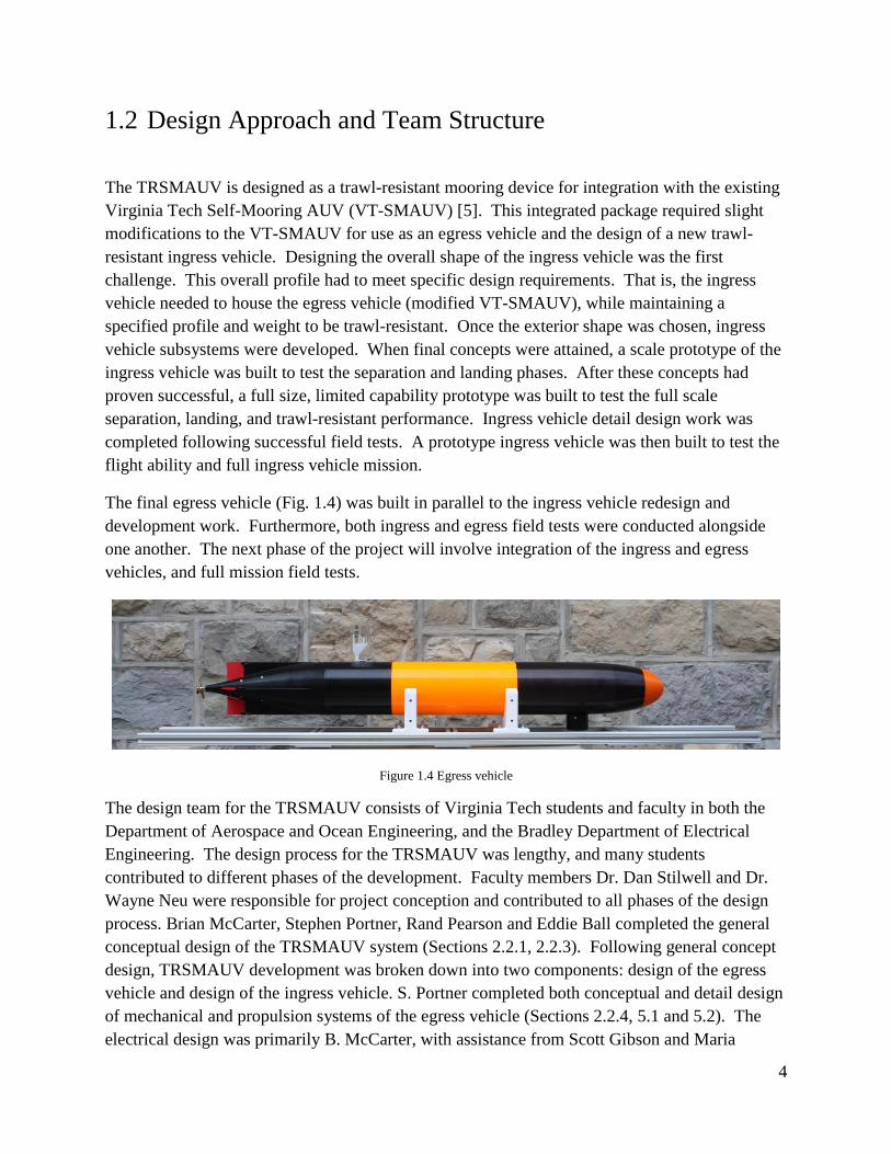
The final egress vehicle (Fig. 1.4) was built in parallel to the ingress vehicle redesign and
development work. Furthermore, both ingress and egress field tests were conducted alongside
one another. The next phase of the project will involve integration of the ingress and egress
vehicles, and full mission field tests.
Figure 1.4 Egress vehicle
The design team for the TRSMAUV consists of Virginia Tech students and faculty in both the
Department of Aerospace and Ocean Engineering, and the Bradley Department of Electrical
Engineering. The design process for the TRSMAUV was lengthy, and many students
contributed to different phases of the development. Faculty members Dr. Dan Stilwell and Dr.
Wayne Neu were responsible for project conception and contributed to all phases of the design
process. Brian McCarter, Stephen Portner, Rand Pearson and Eddie Ball completed the general
conceptual design of the TRSMAUV system (Sections 2.2.1, 2.2.3). Following general concept
design, TRSMAUV development was broken down into two components: design of the egress
vehicle and design of the ingress vehicle. S. Portner completed both conceptual and detail design
of mechanical and propulsion systems of the egress vehicle (Sections 2.2.4, 5.1 and 5.2). The
electrical design was primarily B. McCarter, with assistance from Scott Gibson and Maria

5
Khater. S. Portner completed conceptual mechanical design of the ingress vehicle (Sections
2.2.3.3 and 2.2.4). Additionally, S. Portner completed detail design work for both the ingress
scale model and ingress limited prototype (Chapters 3 and 4). Taylor Wilson performed the
detail mechanical design of the final ingress vehicle prototype (Chapter 6), with assistance from
E. Ball. This included design of mechanical components for various subsystems and integration
of subsystems into the prototype vehicle. T. Wilson performed structural analysis using finite
element analysis (FEA) methods where applicable (Sections 6.5 and 6.6). B. McCarter
performed initial electrical design, while S. Gibson completed detail electrical design, with
assistance from M. Khater. Ingress vehicle propulsion system design was handled primarily by
E. Ball (Section 6.2). Computational fluid dynamic (CFD) analysis of both the ingress and
egress vehicles was completed by E. Ball (Sections 2.2.2, 6.1 and 6.3)
1.3 Thesis Layout
This thesis covers the various phases of the TRSMAUV design process, with the focal point
being the mechanical design of the ingress vehicle prototype. The first few chapters cover
elements of the process that lead up to the mechanical design of the ingress vehicle prototype.
This background information includes: chapter 2, which covers general conceptual design of the
TRSMAUV, as well as conceptual design of some of the subsystems; chapter 3, which covers
the building and testing of a scale model ingress vehicle; chapter 4, which covers the design,
building and testing of a full size limited ingress vehicle prototype; and chapter 5, which covers
the design, building and testing of the egress vehicle. Chapter 6 is the focus of this paper and
covers the detail mechanical design work for the ingress vehicle prototype. Chapter 7 covers the
next stages that are required to complete the TRSMAUV project.

6
2 Conceptual Design
The initial concept was to design a trawl-resistant mooring capability for the existing Virginia
Tech Self-Mooring AUV. A detailed description of the original VT-SMAUV can be found in
[5]. The trawl-resistant concept required the development of an ingress vehicle that could be
moored on the seafloor. The ingress vehicle would house an egress vehicle of similar design to
the VT-SMAUV. The ingress vehicle would rely on the egress vehicle for many functions. The
ingress vehicle will display the principle characteristics of a traditional trawl-resistant mount
(Fig. 2.1) in addition to having an exterior shape consistent with controlled flight. The ingress
vehicle needs to perform several functions during the mission profile described in section 1.1.
Conceptual ideas for these capabilities are described in the following sections of this document.
Several modifications were made to the VT-SMAUV design to produce the egress vehicle. The
conceptual ideas behind these modifications are also briefly described in this document.
Figure 2.1 Traditional trawl-resistant mooring manufactured by Mooring Systems, Inc [9]
2.1 Egress Vehicle
As few modifications as possible were made to the VT-SMAUV to minimize the engineering
effort required to design and build a suitable egress vehicle. The two largest modifications were
to the power budget and the nose design of the vehicle. The egress vehicle only needs to carry

7
enough power to complete the egress portion of the mission as described in Section 1.1. This is
because the egress vehicle will draw from the ingress vehicle batteries during the ingress mission
phase. This power sharing feature enabled the Team to reduce the overall length of the VT-
SMAUV from 74 to 61 inches. The important modification to the nose design occurred as the
egress vehicle no longer needs to carry the false nose as a mooring anchor. Instead, the nose
must contain an electrical connection to the ingress vehicle. This “umbilical” is disconnected to
complete the egress vehicle release phase of the mission.
Figure 2.2 Virginia Tech Self-Mooring AUV shown without the false nose, which functions as a mooring anchor
2.2 Ingress Vehicle
The TRSMAUV ingress vehicle has far more design constraints than a typical general purpose
AUV. This is necessary as the vehicle must be both trawl-resistant and capable of efficient,
controlled flight. It is possible to generally consider the internal components necessary for the
ingress vehicle into the following categories:
1. The egress vehicle: The egress vehicle size is reduced by making the modifications
described in Section 2.1 to the VT-SMAUV. This vehicle will still host the payload,
most electronics, and all computational hardware/software. All guidance and control
functions will reside in the egress vehicle.

8
2. Disposable buoyancy: The ingress vehicle is only required to be positively buoyant
during the ingress portion of the mission. Inexpensive pressure bottles can be used to
store air as buoyancy as this will occur at shallow depths.
3. Batteries: The ingress vehicle will house all batteries necessary for all phases of the
mission profile except the egress phase.
4. Propulsion and control systems: The ingress vehicle will need its own propulsion system
and control surfaces to navigate to the mooring location and successfully descend to the
sea floor. These systems can be inexpensive because they will be primarily operated near
the sea surface.
Figure 2.3 Hypothetical ingress vehicle [7]
2.2.1 Exterior Shape Design
The design of the exterior shape of the ingress vehicle must incorporate the trawl-resistant
bottom mount requirements. This design was based on conventional trawl-resistant systems.
Review of earlier work to develop trawl-resistant bottom mounts showed several common
features to consider. The overall size of the bottom mount also had to be sufficient to house the
egress vehicle.
1. Wet weight while moored: Wet weight can be specified as the force exerted over the
bottom surface area of the trawl-resistant mount while moored. Bottom force per surface
area in previous reported trawl-resistant mount designs ranges from 0.03-0.08 psi [1-3].

9
2. Side slope: The sides of trawl-resistant bottom mounts have a shallow slope so that
trawl cables are passively directed over the mount. The slope relative to the horizontal
ranges between 25 and 40 degrees ([1] and [2] respectively) in previous trawl-resistant
mount designs.
3. Bottom structures: The underside of the bottom mount is occasionally equipped with a
vertical lip. In the case of the Barney trawl-resistant bottom mount, a downward
projecting lip around the circumference of the mount is used in muddy conditions, but is
omitted for sandy bottoms [3]. In the case of the MSI trawl-resistant bottom mount, the
frustum-shaped cover rests upon a 1 inch thick gridded panel base, which may reduce
settling into soft sediments of the seafloor [2].
The wet weight while moored and the side-slope are principle design constraints. As the ingress
vehicle must originally be neutrally buoyant, the buoyant force of the disposable buoyancy is
dependent on the desired wet weight while moored. The desired wet weight will be chosen
based on the appropriate bottom pressure.
In addition to bottom wet weight and side slope, consideration was given to the following
criteria:
1. Minimum dry weight and size to make handling and deployment as easy as possible
2. Physical robustness sufficient to survive impact by trawl itself (e.g., trawl footrope, mud
gear, roller gear) or trawl components (i.e., trawl bridle, trawl door)
3. Minimum cost for unrecoverable components
4. Use of nonmagnetic materials
2.2.2 Preliminary Hydrodynamic Analysis
A preliminary hydrodynamic analysis of the ingress vehicle was performed to determine if the
device could achieve controlled flight. The exterior shape of the vehicle is dramatically different
from other submersible vehicles. Computational fluid dynamic (CFD) methods were used to
conduct the analysis [6].

10
Shell Design 2.2.2.1
It was necessary to have an accurate CAD model of the ingress vehicle exterior shape for the
CFD analysis. A notional shell was designed based on the trawl-resistant design constraints
described in Section 2.2.1, the estimated size of the egress vehicle, and basic hydrodynamic
principles. This shell profile would be used in all of the CFD analysis to determine
hydrodynamic feasibility.
The notional shell is depicted in Fig. 2.4. The maximum sideslope of the shell is 37.5 degrees,
while the minimum sideslope is 27.1 degrees. This kept the sideslope well within the trawl-
resistant parameters (described in Section 2.2.1) while maintaining a hydrodynamic design. An
initial wet weight was chosen so that the bottom pressure would be 0.03 psi. This value is at the
minimum of the valid bottom pressures. It was chosen to reduce the overall weight of
TRSMAUV. Reduction of the overall weight reduces the amount of buoyancy to add to the
ingress vehicle and reduces out-of-water handling difficulties.
Figure 2.4 Exterior shell dimensions for the ingress vehicle
CFD Analysis 2.2.2.2
The CFD simulation determined the hydrodynamic effects on the body when fully submerged
and traveling at 2 m/s through water. It was evident that using such a drastically asymmetric
body generated a large pitching moment, which would be very difficult to control. This pitching
moment is a result of the lift and drag forces experienced by the body, and is illustrated in Fig.
2.5.

11
The initial ingress vehicle generated:
1. Drag = 67.37 N @ 2 m/s
2. Lift = 259.1 N @ 2 m/s
3. Pitch Moment = -255.6 N-m (about approx. centroid of vol.) @ 2 m/s
Figure 2.5 CFD results from the one-sided ingress vehicle [6]
The proposed solution to minimize pitching was to mirror the shell, creating a double sided body
with horizontal plane symmetry. This created a more stable body that would reduce control and
propulsion difficulties. The CFD analysis indicated that this body experienced significantly less
drag, which resulted in a more efficient vehicle (Fig. 2.6).
The two sided version of the ingress vehicle generated:
1. Drag = 54.6 N @ 2 m/s
2. Lift = 0 N @ 2 m/s
3. Pitch Moment = 0 N (about approx. centroid of vol.) @ 2 m/s
Figure 2.6 CFD results for double sided symmetric body [6]

12
The hydrodynamic analysis clearly demonstrated that a body with horizontal plane symmetry
was desirable. This increased the overall complexity for the ingress vehicle and TRSMAUV
because only half of the body was required for mooring.
2.2.3 Overall Systems Layout
Using two symmetric halves for the ingress vehicle introduced more design complications. The
bottom half would be the mooring package. It would be heavier than the water it displaced and
would be positioned on the bottom of the ingress vehicle to ensure roll and pitch stability. Most
of the bottom half design would be constrained by the requirements generated in Section 2.2.1.
It was important to place control surfaces, propellers, and any other external structures needed
for flight and communication in the top half to minimize the vertical relief of the bottom half and
thus maximize the trawl-resistance. The weight of the full ingress vehicle is conditional on the
desired wet weight of the bottom-half mooring package. To maintain stability and obtain the
desired buoyancy for the complete ingress vehicle, all of the positive buoyancy must be located
in the top half. The ingress vehicle must mechanically separate the halves and perform passive
descent and landing on the sea floor.
Buoyancy Control 2.2.3.1
As described in Section 2.2, a large portion of the buoyancy in the ingress vehicle will be
disposable. This buoyancy is only required at shallow depths so air tanks will not be subject to
the large crush pressures that exist at greater depths. These air tanks will be flooded prior to the
helical descent stage of the mission. The tanks will be located within the ingress vehicle and
thus will be part of the disposable portion of the TRSMAUV. When designing these buoyancy
tubes several design constraints were considered:
1. Minimum cost: These components will be part of the disposable ingress vehicle and will
be made from readily available materials that are cost effective and easy to machine (i.e.
PVC pipe).
2. Simplicity and reliability: Failure to flood could compromise the entire mission
3. Rapid flooding: To deploy the TRSMAUV where large currents may be present, it is
necessary to execute the buoyancy release and helical descent as rapidly as possible.
This will increase the chance that the vehicle lands within the CEP.
13
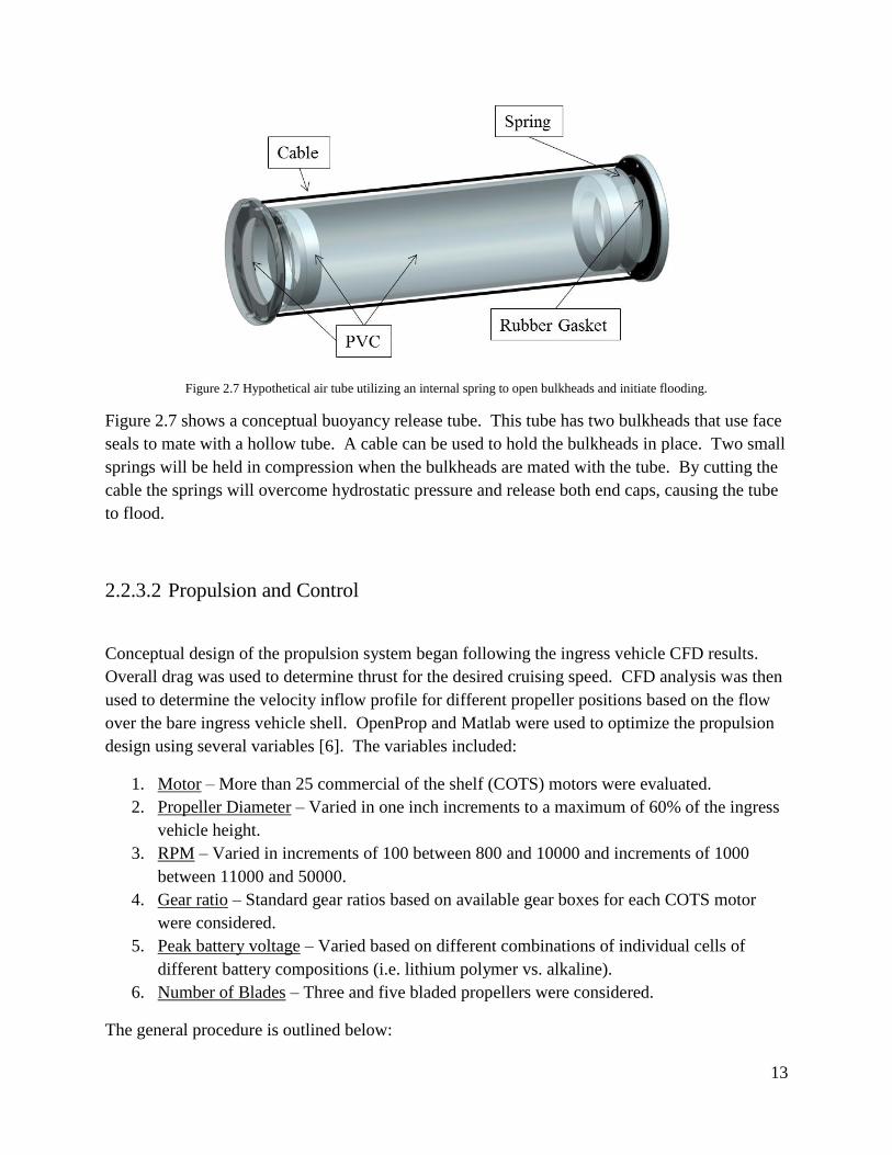
Figure 2.7 Hypothetical air tube utilizing an internal spring to open bulkheads and initiate flooding.
Figure 2.7 shows a conceptual buoyancy release tube. This tube has two bulkheads that use face
seals to mate with a hollow tube. A cable can be used to hold the bulkheads in place. Two small
springs will be held in compression when the bulkheads are mated with the tube. By cutting the
cable the springs will overcome hydrostatic pressure and release both end caps, causing the tube
to flood.
Propulsion and Control 2.2.3.2
Conceptual design of the propulsion system began following the ingress vehicle CFD results.
Overall drag was used to determine thrust for the desired cruising speed. CFD analysis was then
used to determine the velocity inflow profile for different propeller positions based on the flow
over the bare ingress vehicle shell. OpenProp and Matlab were used to optimize the propulsion
design using several variables [6]. The variables included:
1. Motor – More than 25 commercial of the shelf (COTS) motors were evaluated.
2. Propeller Diameter – Varied in one inch increments to a maximum of 60% of the ingress
vehicle height.
3. RPM – Varied in increments of 100 between 800 and 10000 and increments of 1000
between 11000 and 50000.
4. Gear ratio – Standard gear ratios based on available gear boxes for each COTS motor
were considered.
5. Peak battery voltage – Varied based on different combinations of individual cells of
different battery compositions (i.e. lithium polymer vs. alkaline).
6. Number of Blades – Three and five bladed propellers were considered.
The general procedure is outlined below:
14
1. Use CFD to determine velocity inflow profile and vehicle drag profile
2. Use OpenProp to determine torque vs rpm curves for each propeller diameter and
number of blades
3. Use a Matlab script to match each COTS motor with each propeller diameter by
finding the intersection of torque vs. rpm propeller curve with torque vs. rpm
motor curves. This is completed over a combination of assumed battery voltages
and gear ratios.
4. Calculate overall efficiency of each motor/propeller combination
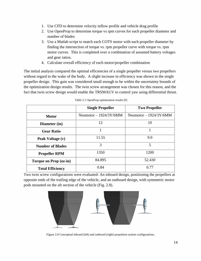
The initial analysis compared the optimal efficiencies of a single propeller versus two propellers
without regard to the wake of the body. A slight increase in efficiency was shown in the single
propeller design. This gain was considered small enough to be within the uncertainty bounds of
the optimization design results. The twin screw arrangement was chosen for this reason, and the
fact that twin screw design would enable the TRSMAUV to control yaw using differential thrust.
Table 2.1 OpenProp optimization results [6]
Single Propeller Two Propeller
Motor Neumotor – 1924/3Y/6MM Neumotor – 1924/3Y/6MM
Diameter (in) 12 10
Gear Ratio 1 1
Peak Voltage (v) 11.55 9.9
Number of Blades 3 5
Propeller RPM 1350 1200
Torque on Prop (oz-in) 84.895 52.430
Total Efficiency 0.84 0.77
Two twin screw configurations were evaluated: An inboard design, positioning the propellers at
opposite ends of the trailing edge of the vehicle, and an outboard design, with symmetric motor
pods mounted on the aft section of the vehicle (Fig. 2.8).
Figure 2.8 Conceptual inboard (left) and outboard (right) propulsion system configurations.
15
The outboard configuration offered several benefits over the inboard design: 1) External motor
pods could rotate for pitch control, removing the need for elevators. 2) Increased propeller
spacing would lead to a finer turn radius. However, these external pods would have a negative
effect on the overall drag of the vehicle and could reduce overall propulsive efficiency. The
mechanical integration of the outboard pods was considered to be more complicated than the
inboard configuration.
The inboard design reduces drag, however each propeller will be operating in the wake of the
vehicle thus reducing propeller efficiency. This design requires the addition of external flaps for
pitch control. Final propulsion design (Section 6.2) was completed following validation of some
of the novel mechanical/hydrodynamic systems in the ingress vehicle. Many design features had
to be completed and validated prior to detail propulsion design.
Attachment & Separation 2.2.3.3
Another system introduced into the two body ingress design is the attachment/separation
mechanism of the two halves. The two halves of the vehicle must be fastened together with
enough strength to resist several forces. This connection will experience a large static load
generated by the difference in buoyancy of the top and bottom halves (estimated as 250 lbs).
There will also be hydrodynamic forces induced on the body while it is underway. In addition to
these known loads, additional dynamic loads could be exerted on the vehicle during initial
deployment and must be considered.
The connections between the two body halves must be reliably severed to allow successful
completion of the separation phase of the mission. Failure of this phase would result in mission
failure and potential loss of the egress vehicle.
Some of the principal mechanisms evaluated for use as the separation connection are listed
below:
1. Latch Mechanism: Several latches were considered necessary to connect different points
of the top and bottom halves. Each latch would be released by a servo either
independently or simultaneously.
2. Pyrotechnic Mechanism: Use of exploding bolts, similar to those used in rocket stage
separation, were considered.
3. Non-Pyrotechnic Release Actuator: Use of one or several actuators specifically designed
to release fasteners were considered.
The latch mechanism was selected for preliminary testing. This was chosen primarily because it
proved to be extremely cost effective. That is, it was the least expensive mechanism that was
16
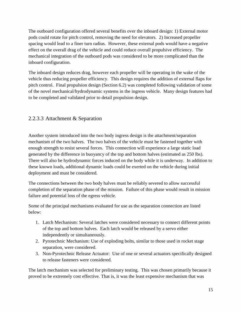
robust, simple and highly reliable. Pyrotechnic mechanisms can be cost effective, however they
are often considered “live ammunition” and can add complication to handling and deployment
regulation.
Figure 2.9 Hypothetical separation mechanism [7]
The hypothetical latch mechanisms consisted of a rotary latch linked to a servo enclosed in a
watertight housing (Fig. 2.9). The rotary latch secures to a pin in the opposing half. By
actuating the servo the linkage transmits the force to the latch release lever and releases the
connection.
Mooring 2.2.3.4
The ingress vehicle can no longer be actively controlled after separation of the halves. Several
different decent and mooring methods were considered. Considered landing requirements
included:
1. Land within a 200 m CEP of the last GPS fix assuming an unknown current with a
magnitude of ≤ 0.25 m/s
2. Soft landing to prevent damage to hull or components.
3. Mooring package correctly oriented to achieve trawl-resistant state.
Several options were investigated based on these criteria. Time of separation is critical because
the ingress vehicle will lose control authority after separation. Simulation studies determined
that an uncontrolled descent from the surface would not be reliable enough to result in a soft
landing within the required CEP. Separation must occur near the sea floor. This would allow
the ingress vehicle to be controlled for the majority of the descent.
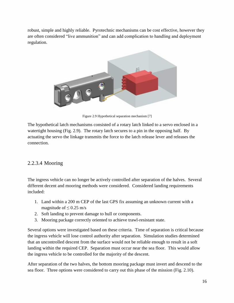
After separation of the two halves, the bottom mooring package must invert and descend to the
sea floor. Three options were considered to carry out this phase of the mission (Fig. 2.10).
17
1. Two halves connected at four corners
2. Two halves connected at one point
3. Bottom half deploys drogue
Figure 2.10 Conceptual descent options.
It proved very difficult to accurately simulate the separation, descent and landing to compare
these configurations. Specifically, how the two halves will behave after separation and how the
linked halves will continue descent. To determine the best option, a scale model was built. The
design and testing of this model is described in Chapter 3.
2.2.4 Egress Vehicle Release
After a predetermined amount of time on the seafloor, the inverted half of the ingress vehicle
must release the egress vehicle. This operation begins with separation of the top cap to expose
the egress vehicle (Fig. 2.11). Buoyant force was determined to be a simple and effective
method for releasing both the top cap of the mooring package and the egress vehicle from the
mooring package. The top cap must be attached firmly enough to survive impact by trawl
equipment during the moored phase of the mission. It must also be effectively released to allow
the egress vehicle to exit the mooring mount. The electrical connection between the egress
vehicle and the bottom mount must also be disconnected. Both of these mechanisms will be
located in the bottom mount which will remain on the seafloor and is a single use system.
Because the seafloor mount system is designed as a disposable piece of hardware, it was
important to keep cost for this assembly to a minimum. Simplicity and reliability were also
important to decrease the chance of failure and reduce the number of design modifications for
the egress vehicle nose [7].
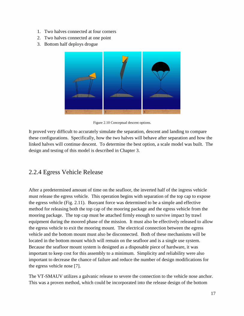
The VT-SMAUV utilizes a galvanic release to severe the connection to the vehicle nose anchor.
This was a proven method, which could be incorporated into the release design of the bottom
18
mount top cap. The top cap will be connected to the bottom mount using several latches. These
latches will mate with removable pins in the bottom mount. Each pin is connected to a spring
held in tension by a fixed cable. A galvanic release will be positioned on a separate cable
holding the spring in tension. By activating the galvanic release the cable can be severed, this
will allow the spring to pull the pin from the latch disconnecting the top cap. A large amount of
positive buoyancy will be located in the top cap. After the latch and pin assembly is
disconnected this buoyancy will cause the top cap to lift off the bottom mount and drift free.
Figure 2.11 Mooring package top cap release [7]
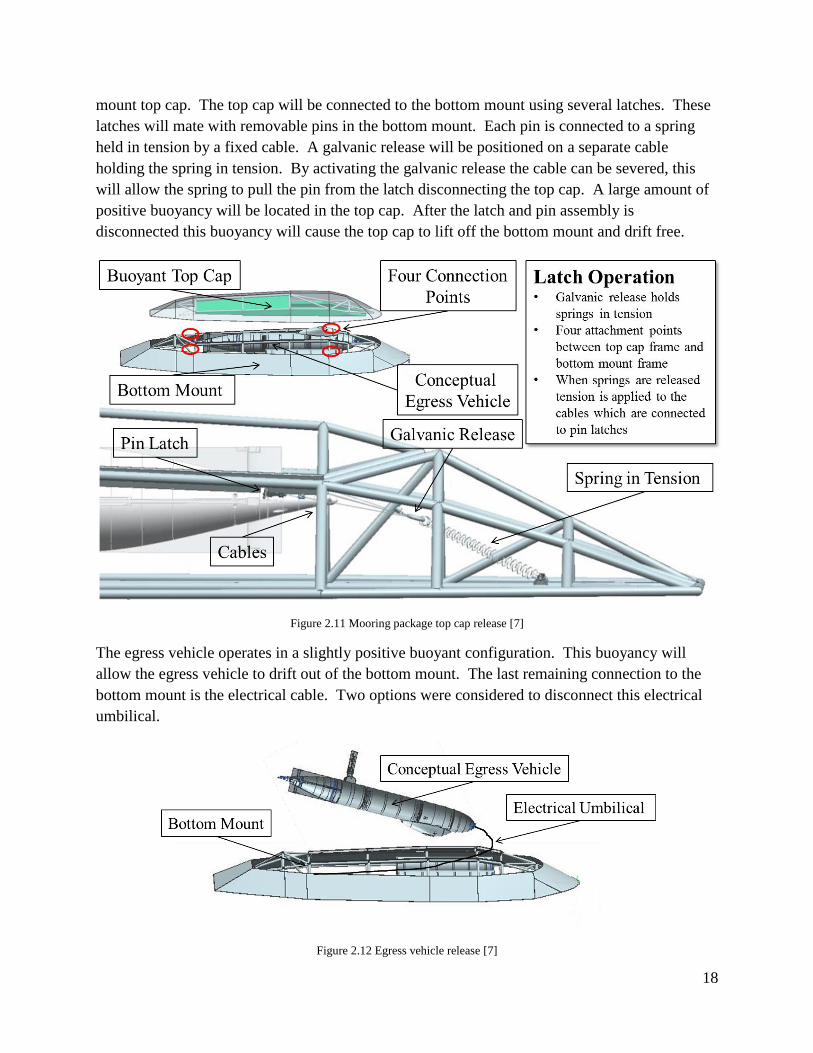
The egress vehicle operates in a slightly positive buoyant configuration. This buoyancy will
allow the egress vehicle to drift out of the bottom mount. The last remaining connection to the
bottom mount is the electrical cable. Two options were considered to disconnect this electrical
umbilical.
Figure 2.12 Egress vehicle release [7]
19
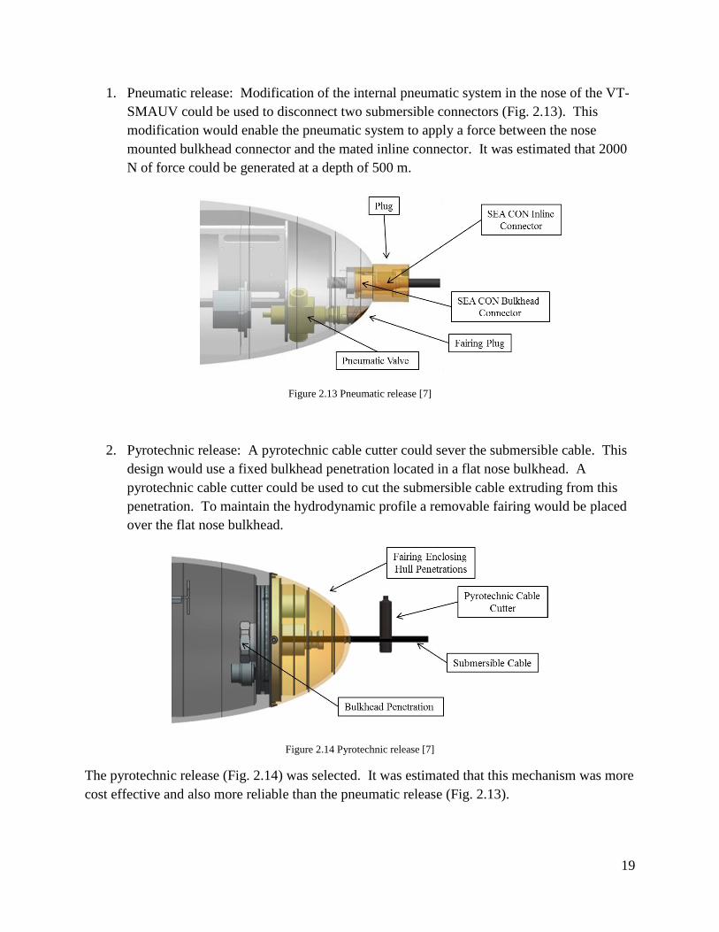
1. Pneumatic release: Modification of the internal pneumatic system in the nose of the VT-
SMAUV could be used to disconnect two submersible connectors (Fig. 2.13). This
modification would enable the pneumatic system to apply a force between the nose
mounted bulkhead connector and the mated inline connector. It was estimated that 2000
N of force could be generated at a depth of 500 m.
Figure 2.13 Pneumatic release [7]
2. Pyrotechnic release: A pyrotechnic cable cutter could sever the submersible cable. This
design would use a fixed bulkhead penetration located in a flat nose bulkhead. A
pyrotechnic cable cutter could be used to cut the submersible cable extruding from this
penetration. To maintain the hydrodynamic profile a removable fairing would be placed
over the flat nose bulkhead.
Figure 2.14 Pyrotechnic release [7]
The pyrotechnic release (Fig. 2.14) was selected. It was estimated that this mechanism was more
cost effective and also more reliable than the pneumatic release (Fig. 2.13).
20
3 Ingress Scale Model
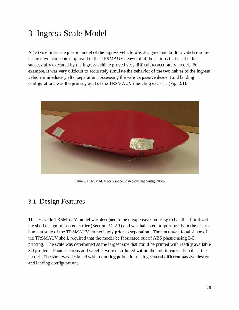
A 1/6 size full-scale plastic model of the ingress vehicle was designed and built to validate some
of the novel concepts employed in the TRSMAUV. Several of the actions that need to be
successfully executed by the ingress vehicle proved very difficult to accurately model. For
example, it was very difficult to accurately simulate the behavior of the two halves of the ingress
vehicle immediately after separation. Assessing the various passive descent and landing
configurations was the primary goal of the TRSMAUV modeling exercise (Fig. 3.1).
Figure 3.1 TRSMAUV scale model in deployment configuration.
3.1 Design Features
The 1/6 scale TRSMAUV model was designed to be inexpensive and easy to handle. It utilized
the shell design presented earlier (Section 2.2.2.1) and was ballasted proportionally to the desired
buoyant state of the TRSMAUV immediately prior to separation. The unconventional shape of
the TRSMAUV shell, required that the model be fabricated out of ABS plastic using 3-D
printing. The scale was determined as the largest size that could be printed with readily available
3D printers. Foam sections and weights were distributed within the hull to correctly ballast the
model. The shell was designed with mounting points for testing several different passive descent
and landing configurations.
21
3.2 Testing
Objectives of the model phase of the project were to evaluate the three descent concepts (Section
2.2.3.4) and select the most suitable descent strategy to develop. To achieve a successful landing
in the descent phase of the mission several things needed to happen:
1. Successful Separation: The bottom half of the ingress vehicle must roll into an inverted
position. This maneuver would be accomplished as a result of weight distribution and the
mooring configuration (three variations described in Section 2.2.3.4).
2. Soft Landing: The bottom half of the ingress vehicle must descend to the seafloor and
land without sustaining damage.
3. Land within CEP: The two halves must land close to the targeted site following the
descent/separation stages.
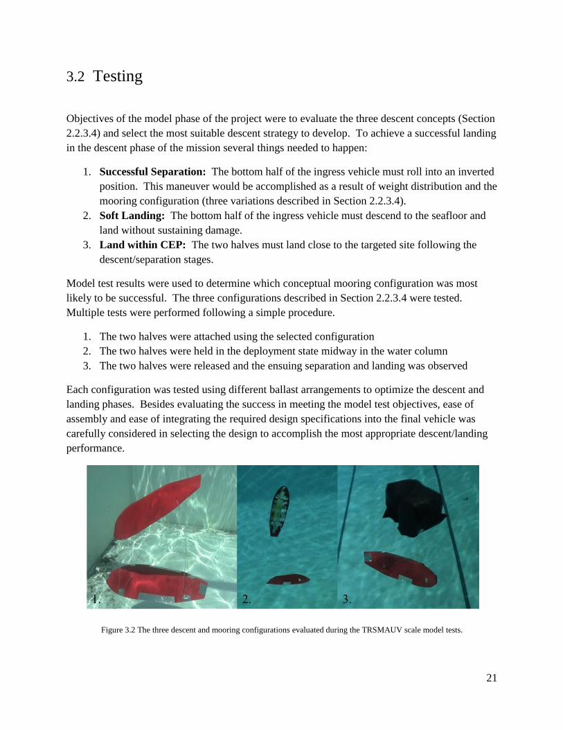
Model test results were used to determine which conceptual mooring configuration was most
likely to be successful. The three configurations described in Section 2.2.3.4 were tested.
Multiple tests were performed following a simple procedure.
1. The two halves were attached using the selected configuration
2. The two halves were held in the deployment state midway in the water column
3. The two halves were released and the ensuing separation and landing was observed
Each configuration was tested using different ballast arrangements to optimize the descent and
landing phases. Besides evaluating the success in meeting the model test objectives, ease of
assembly and ease of integrating the required design specifications into the final vehicle was
carefully considered in selecting the design to accomplish the most appropriate descent/landing
performance.
Figure 3.2 The three descent and mooring configurations evaluated during the TRSMAUV scale model tests.
22
Scale model test results revealed that configuration-2 (two halves connected at one point) was
the most effective descent and landing option (Fig. 3.2). Configuration-1 (two halves connected
at four points) produced a troublesome gliding effect during descent. This increased the
difficulty in predicting where the bottom half would land, thus negatively affecting the desired
CEP. Configuration-3 (bottom half deploys drogue) did not yield any visible benefit over
configuration-2 while adding unnecessary complications and points of failure.
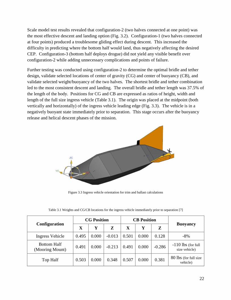
Further testing was conducted using configuration-2 to determine the optimal bridle and tether
design, validate selected locations of center of gravity (CG) and center of buoyancy (CB), and
validate selected weight/buoyancy of the two halves. The shortest bridle and tether combination
led to the most consistent descent and landing. The overall bridle and tether length was 37.5% of
the length of the body. Positions for CG and CB are expressed as ratios of height, width and
length of the full size ingress vehicle (Table 3.1). The origin was placed at the midpoint (both
vertically and horizontally) of the ingress vehicle leading edge (Fig. 3.3). The vehicle is in a
negatively buoyant state immediately prior to separation. This stage occurs after the buoyancy
release and helical descent phases of the mission.
Figure 3.3 Ingress vehicle orientation for trim and ballast calculations
Table 3.1 Weights and CG/CB locations for the ingress vehicle immediately prior to separation [7]
Configuration CG Position CB Position
Buoyancy X Y Z X Y Z
Ingress Vehicle 0.495 0.000 -0.013 0.501 0.000 0.128 -8%
Bottom Half
(Mooring Mount) 0.491 0.000 -0.213 0.491 0.000 -0.286
-110 lbs (for full
size vehicle)
Top Half 0.503 0.000 0.348 0.507 0.000 0.381 80 lbs (for full size
vehicle)
23
4 Ingress Limited Prototype
Some of the novel concepts used in the TRSMAUV could not be adequately tested using the
scale model. Thus, a limited capability, full size prototype was developed for further testing.
This prototype would validate the trawl-resistant capability of the bottom half mooring package,
the latch separation mechanism (Section 2.2.3.3), and the full scale passive mooring.
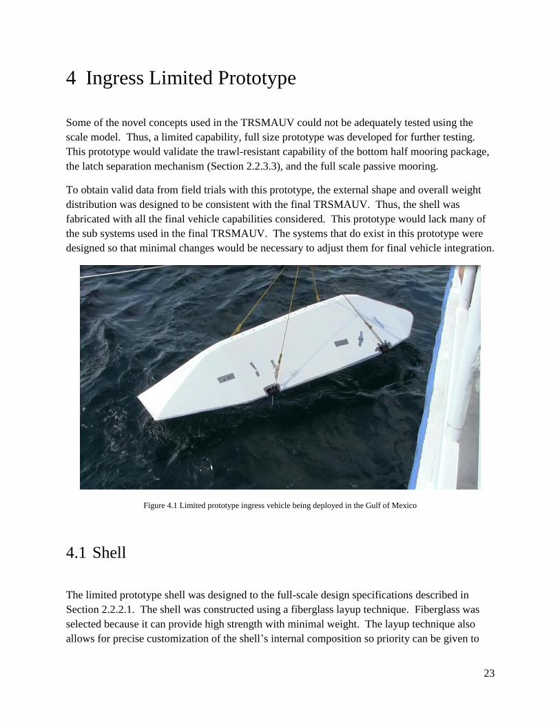
To obtain valid data from field trials with this prototype, the external shape and overall weight
distribution was designed to be consistent with the final TRSMAUV. Thus, the shell was
fabricated with all the final vehicle capabilities considered. This prototype would lack many of
the sub systems used in the final TRSMAUV. The systems that do exist in this prototype were
designed so that minimal changes would be necessary to adjust them for final vehicle integration.
Figure 4.1 Limited prototype ingress vehicle being deployed in the Gulf of Mexico
4.1 Shell
The limited prototype shell was designed to the full-scale design specifications described in
Section 2.2.2.1. The shell was constructed using a fiberglass layup technique. Fiberglass was
selected because it can provide high strength with minimal weight. The layup technique also
allows for precise customization of the shell’s internal composition so priority can be given to
24
strength or weight. This was beneficial as it allowed for customization between the top and
bottom halves of the shell. The top half was fabricated to minimize wet weight, effectively
maximizing the buoyancy. This half only requires enough strength to maintain its shape during
flight. The bottom half shell was fabricated to maximize strength with little concern for weight.
This half must be strong enough to meet the trawl-resistant specifications.
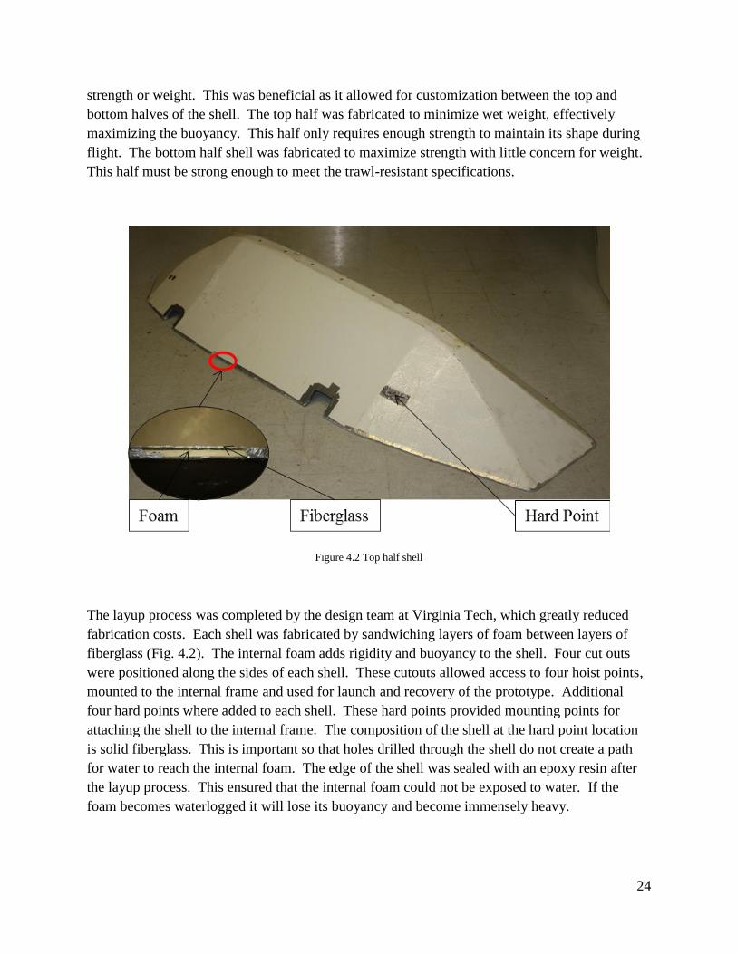
Figure 4.2 Top half shell
The layup process was completed by the design team at Virginia Tech, which greatly reduced
fabrication costs. Each shell was fabricated by sandwiching layers of foam between layers of
fiberglass (Fig. 4.2). The internal foam adds rigidity and buoyancy to the shell. Four cut outs
were positioned along the sides of each shell. These cutouts allowed access to four hoist points,
mounted to the internal frame and used for launch and recovery of the prototype. Additional
four hard points where added to each shell. These hard points provided mounting points for
attaching the shell to the internal frame. The composition of the shell at the hard point location
is solid fiberglass. This is important so that holes drilled through the shell do not create a path
for water to reach the internal foam. The edge of the shell was sealed with an epoxy resin after
the layup process. This ensured that the internal foam could not be exposed to water. If the
foam becomes waterlogged it will lose its buoyancy and become immensely heavy.

25
4.2 Separation
The mechanism to separate the two halves of the limited prototype was based on the rotary latch
conceptual design. Four identical servo and latch assemblies were used to fasten the top frame to
the bottom frame. These separation assemblies were placed near the corners of the framing to
evenly distribute the load. Each assembly was composed of a rotary latch linked to a servo (in a
water tight housing). The latch secures to a horizontal pin fixed to the opposite frame.
Figure 4.3 Separation layout (S. Portner)
The servo and latch portion of the separation assembly were fixed to the top frame. This is
because the other electronics in this prototype are located in the top half shell. By placing the
actuating portion of the separation mechanism in the top half, no electrical connections had to be
severed. All four servos are simultaneously actuated to open the corresponding latches and
release the bottom half to complete the separation phase.
4.3 Mooring
Based on the successful scale model tests, the configuration where two halves were connected at
one point was used for the limited prototype. The bridle and tether assembly was designed to be
37.5% of the total body length of the prototype based on scale model tests. Nylon cord was used
26
for the bridle and tether for the tests. The release of the top half after successful landing was not
tested.
4.4 General Assembly
The overall weight of the limited prototype is determined by the wet weight of the mooring
package (mooring pressure set at 0.03 psi). The overall buoyant state for this prototype must
match what is required immediately prior to separation for valid tests. Ballast was arranged so
that the CG and CB closely matched the most successful scale model tests.
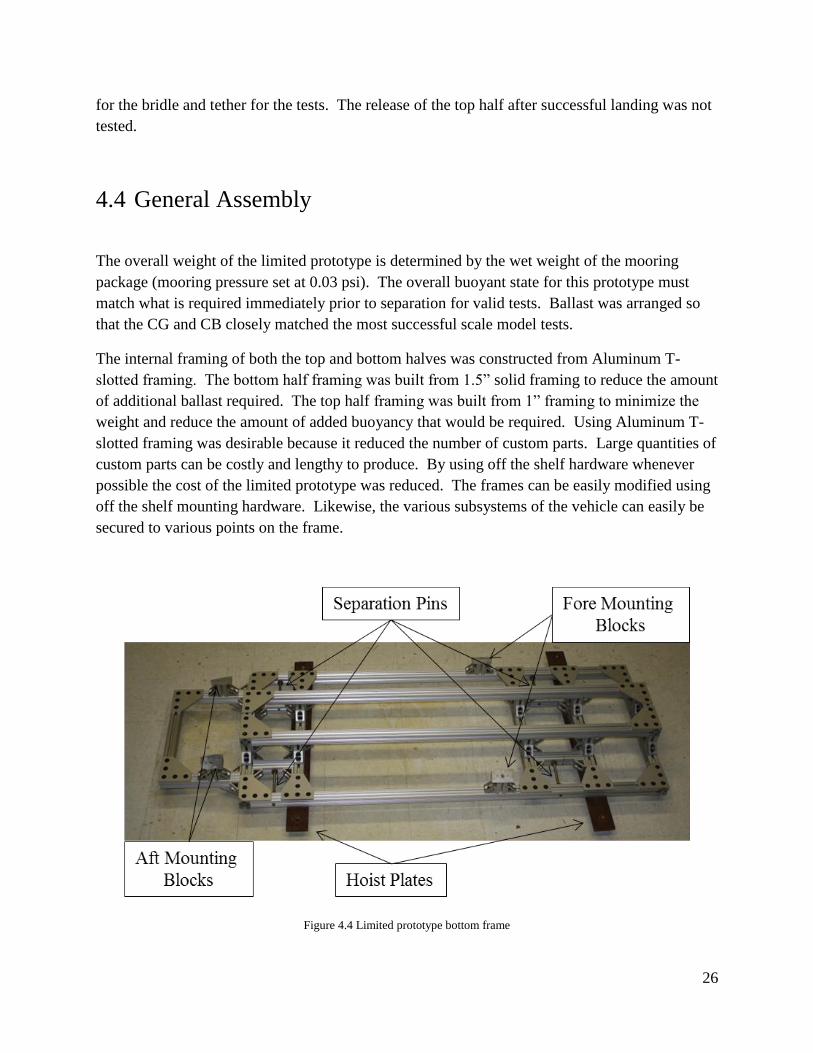
The internal framing of both the top and bottom halves was constructed from Aluminum T-
slotted framing. The bottom half framing was built from 1.5” solid framing to reduce the amount
of additional ballast required. The top half framing was built from 1” framing to minimize the
weight and reduce the amount of added buoyancy that would be required. Using Aluminum T-
slotted framing was desirable because it reduced the number of custom parts. Large quantities of
custom parts can be costly and lengthy to produce. By using off the shelf hardware whenever
possible the cost of the limited prototype was reduced. The frames can be easily modified using
off the shelf mounting hardware. Likewise, the various subsystems of the vehicle can easily be
secured to various points on the frame.
Figure 4.4 Limited prototype bottom frame

27
4.5 Field Test
The limited prototype field tests were largely successful. Separation of the two halves using the
servo actuated rotary latches was unsuccessful. The load applied to the rotary latches was too
much for the servos to overcome. Instead, the two halves were held in a temporary state of
attachment at the surface, held afloat by a line fixed to the boat. Divers used a quick release on
the line to initiate separation. This procedure enabled realistic simulation tests to be conducted
of the mooring phase of the ingress vehicle prototype. Test results demonstrated that following
separation, the bottom half consistently inverted and performed a slow descent coming to a soft
landing on target.
Figure 4.5 Ingress limited prototype separation test
A large chain, with a variety of weights attached to it, was dragged across the deployed mount at
an estimated speed of 4 kts to test the trawl-resistant capability of the mooring package. The
package successfully deflected the chain without sustaining damage and without a significant
change in its moored location through several trials.
Figure 4.6 Ingress limited prototype trawl resistance test

28
5 Egress Vehicle
A prototype egress vehicle was unnecessary as the design is nearly identical to the VT-SMAUV.
The vehicle nose was modified to incorporate the electrical connection to the ingress vehicle.
The external profile of the nose was not altered. This would allow the egress vehicle to use very
similar control algorithms to those used in the VT-SMAUV. Another modification reduced the
battery pack used in the VT-SMAUV. The egress vehicle only requires power for the fifty
nautical mile egress phase of the TRSMAUV mission. Externally, this modification reduced the
overall length of the vehicle. New batteries, with a higher energy density (191 Wh kg⁄ vs.
179 Wh kg⁄ ), were selected that led to a minor modification in the internal mounting
configuration.
Figure 5.1 Field testing the egress vehicle in Claytor Lake, VA
Table 5.1 Egress vehicle specifications
Parameter Specification
Vehicle Diameter 17.53 cm (6.9 in)
Vehicle Length 1.54 m (60.9 in)
Weight in Air 27.5 kg (60.6 lbs)
Maximum Depth 500 m (1600 ft)
Operating Depth Energy 710 Wh
Endurance 10 – 16 hours (depending on operating speed)
Provided by two LiPo 16,000 6S 22.2v battery packs
Propulsion Direct drive DC brushless motor to open 3-bladed
propeller
Velocity Range Operating speed 2 m/s (3.88 knots)
External Hook-Up Ethernet and power Cable
Navigation Attitude Heading and Reference System (AHRS), depth
sensor, and GPS
Tracking Acoustic pinger
CPU/Software 1.7 GHz quad-core Hardkernel ODROID-U3 with a
Gentoo OS

29
5.1 Nose Modifications
Two different conceptual designs were developed to disconnect the electrical connection
between the egress vehicle and the ingress vehicle (Section 2.2.4): A pneumatic release and a
pyrotechnic release. The pyrotechnic release was selected for use in the final egress vehicle.
This mechanism was chosen as it is a simple and very reliable release, which reduced the
complexity of the required nose modifications. Electronic wire cutters were selected. These
cutters could be activated underwater and have a near perfect success rate.
Figure 5.2 VT-SMAUV Nose
The egress vehicle nose was redesigned so that a section of the water-tight hull has a flat
bulkhead. This was done so all hull penetrations could be moved to this bulkhead. A removable
plastic conical fairing was designed to be positioned over this bulkhead to replicate the external
profile of the VT-SMAUV. By relocating the hull penetrations to this nose bulkhead, the fairing
located underneath the nose of the VT-SMAUV could be entirely removed. This reduces drag
and increases the overall efficiency of the vehicle. A small hole is positioned in the center of the
nose fairing for the electrical umbilical to pass through (Fig. 5.3).
Figure 5.3 Egress vehicle nose

30
A second depth sensor was added to the nose. The original depth sensor in the VT-SMAUV is
located in the tail bulkhead between the oil filled tail section and the air filled tube section of the
vehicle. The addition of the second depth sensor gives the egress vehicle the ability to monitor
the oil pressure in the tail section. The vacuum valve assembly on the VT-SMAUV was also
replaced with a more convenient and lower profile configuration.
Figure 5.4 Egress vehicle nose shown in the configuration for independent field trials.
The egress vehicle nose is configured for independent operation (Fig. 5.4) or for subsequent tests
with the ingress vehicle. A 903 series Teledyne Benthos transducer is installed beneath the nose
in this configuration. This acoustic modem uses low and mid frequency ranges for underwater
communication during the independent egress vehicle tests. The umbilical bulkhead connector
has been replaced with a dummy plug for testing so there are no loose wires.
5.2 Tube Modifications
The middle section of the egress vehicle was modified from the VT-SMAUV design. The
battery pack required by the egress vehicle is much smaller than the pack in the VT-SMAUV.
This reduction in size reduced the length of the middle section of the egress vehicle. The VT-
SMAUV middle section comprises several 10 inch long tube sections. Each tube section
connection adds another seam that can become damaged and lead to a loss of water-tight
integrity. These short tube sections were replaced with a single 17” long tube in the egress
vehicle. This change reduced the length of the egress vehicle by 13” to 61” overall.
31
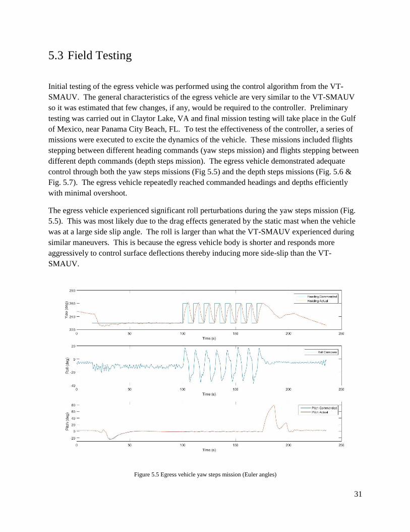
5.3 Field Testing
Initial testing of the egress vehicle was performed using the control algorithm from the VT-
SMAUV. The general characteristics of the egress vehicle are very similar to the VT-SMAUV
so it was estimated that few changes, if any, would be required to the controller. Preliminary
testing was carried out in Claytor Lake, VA and final mission testing will take place in the Gulf
of Mexico, near Panama City Beach, FL. To test the effectiveness of the controller, a series of
missions were executed to excite the dynamics of the vehicle. These missions included flights
stepping between different heading commands (yaw steps mission) and flights stepping between
different depth commands (depth steps mission). The egress vehicle demonstrated adequate
control through both the yaw steps missions (Fig 5.5) and the depth steps missions (Fig. 5.6 &
Fig. 5.7). The egress vehicle repeatedly reached commanded headings and depths efficiently
with minimal overshoot.
The egress vehicle experienced significant roll perturbations during the yaw steps mission (Fig.
5.5). This was most likely due to the drag effects generated by the static mast when the vehicle
was at a large side slip angle. The roll is larger than what the VT-SMAUV experienced during
similar maneuvers. This is because the egress vehicle body is shorter and responds more
aggressively to control surface deflections thereby inducing more side-slip than the VT-
SMAUV.
Figure 5.5 Egress vehicle yaw steps mission (Euler angles)

32
Figure 5.6 Egress vehicle depth steps mission (Euler angles)
Figure 5.7 Egress vehicle depth steps mission (depth)
The VT-SMAUV controller proved to be satisfactory for egress vehicle operation. However, a
new, more appropriate, controller is in development and will be tuned with further field testing.

33
6 Ingress Vehicle Prototype
A final prototype ingress vehicle was designed and built to test the flight ability, buoyancy
release, helical descent, separation and landing after successful validation of the full scale novel
concepts used in the TRSMAUV (Chapter 4). The internal layout of this prototype’s sub
systems is nearly identical to the final TRSMAUV. Although this prototype was designed with
space to house the egress vehicle, it does not contain the mounting or release hardware.
6.1 Stability
The unusual shape of the TRSMAUV ingress vehicle presented many stability problems.
Vehicle stability can be decomposed into three important dimensions: pitch, roll and yaw.
Stability can be further decomposed into two different states: static (the vehicle is not moving),
and dynamic (the vehicle is moving). Static yaw stability is not a concern because the
TRSMAUV is only required to maintain a specific yaw heading while moving.
In a static state, only pitch and roll stability were addressed. In a dynamic state, stability is
required in all three dimensions (pitch, yaw and roll). Dynamic stability is required for efficient
controlled flight. While moving, the hydrodynamic forces experienced in the yaw and roll
dimensions are relatively small, because of this, passive dynamic stability can be achieved.
Dynamic stability in pitch is more difficult due to the large hydrodynamic forces experienced
while underway. This vehicle utilizes different mechanical systems to achieve active dynamic
stability in pitch (Section 6.3).
Static stability in pitch and roll can be obtained in marine vehicles by the correct placement of
vehicle CG and CB. A large vertical separation between the CG and CB leads to good static
stability in pitch and roll. While underway hydrodynamic forces affecting roll are minimal, thus
dynamic stability in roll can also be gained from the placement of CG and CB. The longitudinal
and latitudinal positions of the CB and CG are also important. Inconsistencies in this placement
can lead to undesirable vehicle list or trim. The ingress vehicle design placed the heavy bottom
half mooring package underneath the buoyant top half creating a significant separation between
CB and CG. This provided static stability in pitch and both static and dynamic stability in roll
without negatively affecting the position of other vehicle subsystems.
A fixed skeg was added to the aft section of the vehicle to achieve sufficient dynamic stability in
yaw. The correct sizing of this skeg required a detailed analysis of the hydrodynamic forces
experienced by the ingress vehicle with no skeg. A steady CFD analysis was run on the ingress
vehicle body at multiple yaw angles of attack (Fig. 6.1) [6].
34
Figure 6.1 CFD simulation set up [6]
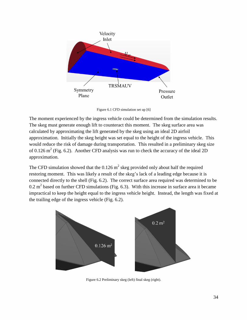
The moment experienced by the ingress vehicle could be determined from the simulation results.
The skeg must generate enough lift to counteract this moment. The skeg surface area was
calculated by approximating the lift generated by the skeg using an ideal 2D airfoil
approximation. Initially the skeg height was set equal to the height of the ingress vehicle. This
would reduce the risk of damage during transportation. This resulted in a preliminary skeg size
of 0.126 m2 (Fig. 6.2). Another CFD analysis was run to check the accuracy of the ideal 2D
approximation.
The CFD simulation showed that the 0.126 m2 skeg provided only about half the required
restoring moment. This was likely a result of the skeg’s lack of a leading edge because it is
connected directly to the shell (Fig. 6.2). The correct surface area required was determined to be
0.2 m2 based on further CFD simulations (Fig. 6.3). With this increase in surface area it became
impractical to keep the height equal to the ingress vehicle height. Instead, the length was fixed at
the trailing edge of the ingress vehicle (Fig. 6.2).
Figure 6.2 Preliminary skeg (left) final skeg (right).

35
Many uncertainties remained on how the skeg would affect the stability of the ingress vehicle
during field trials. For this reason, the skeg was ultimately designed so that it could be easily
replaced with alternate skeg designs, if needed.
Figure 6.3 Skeg surface area required to produce zero net moment at various yaw angles of attack [6]
6.2 Propulsion
The preliminary CFD analysis (Section 2.2.3.2) resulted in the decision to use a twin screw
configuration. This produced a similar efficiency to the single screw system but provided
several benefits compared to the single screw configuration. The most important benefit was the
ability to control yaw using differential thrust. Further analysis was necessary to determine
whether the dual screw optimal configuration was inboard or outboard (completed by E. Ball).
Two CAD models that included the final skeg designs and hypothetical elevators for the inboard
configuration were used for the CFD analysis (Fig. 6.4).
Figure 6.4 CAD models used for CFD analysis showing the inboard (left) and outboard (right) propeller configurations.

36
A CFD simulation using these CAD models generated more accurate drag estimates than the
previous CFD work (Section 2.2.2.2). These simulations also generated velocity inflow profiles
for the different propeller positions. The results indicated that the novel shape of the ingress
vehicle produced a large wake leading to a non-uniform velocity inflow profile for the inboard
propellers (Fig. 6.5).
Figure 6.5 Flow velocity profile shown behind the vehicle and behind the motor pod. Note the asymmetry in the flow field
associated with the propeller positioned behind the vehicle [6].
The outboard configuration generated more drag but allowed propellers to operate in a consistent
flow distribution. The inboard configuration reduced drag but the propellers operated in an
inconsistent flow distribution. The area of large velocity deficit in the wake covered
approximately 25% of the propeller disk area. To account for the irregular velocity inflow
profile, it was estimated that the inboard propellers produced 25% less thrust, due to the blades
stalling in this region, than they would if this region were not present. Overall efficiency of each
configuration was determined using CFD simulation, OpenProp, and Matlab. The general
procedure is outlined below and is the same as the initial propulsion analysis (Section 2.2.3.2).
Inboard vs. Outboard Configuration Selection:
1. Use CFD to determine velocity inflow profile and vehicle drag profile.
2. Use OpenProp to determine torque vs rpm curves for each propeller diameter and
number of blades.
3. Use a Matlab script to match each COTS motor with each propeller diameter by
finding the intersection of torque vs rpm propeller curve with torque vs rpm motor
curves. This is completed over a combination of assumed battery voltage and
gear ratios.
4. Calculate overall efficiency of each motor/propeller combination.

37
The best overall vehicle efficiency was very similar for both configurations. Consideration was
given to the mechanical design difficulty of both configurations in making the decision for which
design to choose. The inboard configuration was chosen as the outboard design was estimated to
be more difficult and more expensive to design and implement. The final phase of the
propulsion design stage was to determine an optimal propeller design and pair it with a COTS
motor. This was completed using CFD simulation, OpenProp and XFOIL. For both OpenProp
and XFOIL, design parameters were selected to optimize the propellers for operation in low
Reynolds number ranges. The general procedure is described below.
Propeller Design Optimization:
1. Assume a propeller blade drag profile based on propeller size.
2. Repeat steps 1-3 from the Configuration Selection procedure.
3. Select the optimal COTS motor and propeller pair.
4. Design propeller blades by radial sections based on calculated lift distribution,
axial/tangential velocities, and pitch angle.
i. Calculate lift per unit span based on lift coefficient distribution (determined
from circulation distribution).
ii. Determine chord lengths based on the range of lift coefficients considered.
iii. Specify thickness distributions.
iv. Calculate Reynolds numbers at each radial position for each chord length.
v. Determine the best lift over drag, best camber and best position of max
camber for all lift coefficients considered at each station.
vi. Select the thickness distribution, Reynolds number distribution and lift
coefficient distribution at each station that corresponds to the lift
coefficient maximizing the lift over drag at each station. This maximizes
thrust for a given torque.
vii. Smooth lift coefficient distribution and repeat steps ii – vi.
viii. Calculate propeller drag profile and thrust using XFOIL.
5. Check that the propeller drag profile determined in step 4.viii is similar to the drag
profile used in step 1. If not, use the updated drag profile and repeat steps 1-4.
6. Check propeller for cavitation in OpenProp and alter lift coefficient distribution if
necessary.
7. CAD file is output by OpenProp for rapid prototyping.
8. Use FEA techniques to select a material and manufacturing procedure for
propeller.
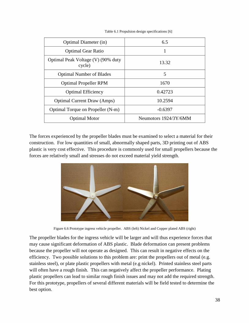
38
Table 6.1 Propulsion design specifications [6]
Optimal Diameter (in) 6.5
Optimal Gear Ratio 1
Optimal Peak Voltage (V) (90% duty
cycle) 13.32
Optimal Number of Blades 5
Optimal Propeller RPM 1670
Optimal Efficiency 0.42723
Optimal Current Draw (Amps) 10.2594
Optimal Torque on Propeller (N-m) -0.6397
Optimal Motor Neumotors 1924/3Y/6MM
The forces experienced by the propeller blades must be examined to select a material for their
construction. For low quantities of small, abnormally shaped parts, 3D printing out of ABS
plastic is very cost effective. This procedure is commonly used for small propellers because the
forces are relatively small and stresses do not exceed material yield strength.
Figure 6.6 Prototype ingress vehicle propeller. ABS (left) Nickel and Copper plated ABS (right)
The propeller blades for the ingress vehicle will be larger and will thus experience forces that
may cause significant deformation of ABS plastic. Blade deformation can present problems
because the propeller will not operate as designed. This can result in negative effects on the
efficiency. Two possible solutions to this problem are: print the propellers out of metal (e.g.
stainless steel), or plate plastic propellers with metal (e.g nickel). Printed stainless steel parts
will often have a rough finish. This can negatively affect the propeller performance. Plating
plastic propellers can lead to similar rough finish issues and may not add the required strength.
For this prototype, propellers of several different materials will be field tested to determine the
best option.

39
Figure 6.7 FEA results on ABS propeller blade (psi) [6]
The blades of a propeller of this design, fabricated out of ABS, may fail when subject to stresses
≥ 6.16 × 10³ psi (yield strength of ABS). Stresses exceeding this value are indicated by shades
of green, yellow, orange and red in the FEA simulation (Fig. 6.7). It should be noted that elastic
deformation may occur well before these stresses, and can have an equally negative effect on
propeller performance.
A final CFD simulation was performed to ensure that the ingress vehicle could overcome the
passive stability generated by the skeg and execute a controlled yaw command. Simulation
estimated that the ingress vehicle can adjust course at roughly 0.5 degrees/second (Fig. 6.8).
This simulation generated a conservative result because it was run assuming one propeller
generating maximum thrust and the other propeller generating zero thrust. Yaw commands
could be executed more rapidly by operating propellers in opposite directions at maximum
thrust.
Figure 6.8 Ingress vehicle yaw command from one propeller at maximum thrust [6]
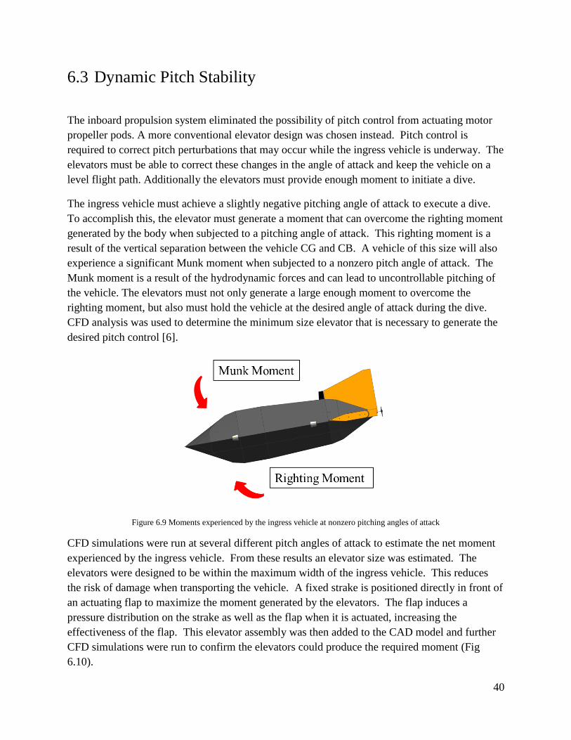
40
6.3 Dynamic Pitch Stability
The inboard propulsion system eliminated the possibility of pitch control from actuating motor
propeller pods. A more conventional elevator design was chosen instead. Pitch control is
required to correct pitch perturbations that may occur while the ingress vehicle is underway. The
elevators must be able to correct these changes in the angle of attack and keep the vehicle on a
level flight path. Additionally the elevators must provide enough moment to initiate a dive.
The ingress vehicle must achieve a slightly negative pitching angle of attack to execute a dive.
To accomplish this, the elevator must generate a moment that can overcome the righting moment
generated by the body when subjected to a pitching angle of attack. This righting moment is a
result of the vertical separation between the vehicle CG and CB. A vehicle of this size will also
experience a significant Munk moment when subjected to a nonzero pitch angle of attack. The
Munk moment is a result of the hydrodynamic forces and can lead to uncontrollable pitching of
the vehicle. The elevators must not only generate a large enough moment to overcome the
righting moment, but also must hold the vehicle at the desired angle of attack during the dive.
CFD analysis was used to determine the minimum size elevator that is necessary to generate the
desired pitch control [6].
Figure 6.9 Moments experienced by the ingress vehicle at nonzero pitching angles of attack
CFD simulations were run at several different pitch angles of attack to estimate the net moment
experienced by the ingress vehicle. From these results an elevator size was estimated. The
elevators were designed to be within the maximum width of the ingress vehicle. This reduces
the risk of damage when transporting the vehicle. A fixed strake is positioned directly in front of
an actuating flap to maximize the moment generated by the elevators. The flap induces a
pressure distribution on the strake as well as the flap when it is actuated, increasing the
effectiveness of the flap. This elevator assembly was then added to the CAD model and further
CFD simulations were run to confirm the elevators could produce the required moment (Fig
6.10).

41
Figure 6.10 Righting moment generated by flaps when deflected at 15 degrees in both directions [6]
The first elevator assembly generated a moment only sufficient to actively control the ingress
vehicle at minimal angles of attack (less than one degree in either direction). Vertical plates
were added to the ends of the fixed strakes and elevator flaps to make the elevators more
effective, without exceeding the maximum width of the vehicle (Fig. 6.11). These plates reduced
vortex shedding along the edge of the elevator and increased the lift. This elevator assembly was
estimated to be capable of generating a moment that could actively control the ingress vehicle at
pitch angles of attack between -7.3 degrees and 5.0 degrees (Fig. 6.10).
Figure 6.11 Elevator assembly
It was necessary to find a suitable actuator for the flap after sizing the elevator assembly. The
flaps were designed using a balanced rudder concept. By placing the shaft at roughly the quarter
chord, the torque on the shaft was reduced. The maximum torque that is exerted on the shaft was
estimated to be 270 oz-in based on the CFD simulations (Fig 6.12). This value was then used to
select a suitable commercially available servo. To account for additional torque from seal losses
and provide an acceptable factor of safety (FoS), servos where selected with a maximum torque
of 500 oz-in.

42
Figure 6.12 Torque experienced by elevator shaft when the flap is at max deflection at various angles of attack [6]
6.4 Buoyancy Control
The ingress vehicle must possess a certain amount of disposable buoyancy as stated earlier
(Section 2.2.3.1). The TRSMAUV executes a one-time change of buoyancy immediately before
the helical descent. To successfully land on target this buoyancy release must occur rapidly.
Buoyancy is supplied from several air tubes in the ingress vehicle. These tubes are designed
with ejectable bulkheads for rapid flooding.
Each tube is constructed from lengths of schedule 40 PVC tubing (6” pipe size). The PVC
tubing provides a suitably strong pressure housing because this buoyancy is only necessary
during the ingress phase of the mission which occurs at shallow depth. Each tube is sealed at
both ends by a solid PVC endcap with a gasket (made of soft silicon based rubber) providing a
face seal. A high strength compression spring is mounted to an internal ring at each end of the
tube and is put into a compressed state while the tube is in its buoyant state. In the buoyant state
the two endcaps are held in place by high strength stretch resistant line (Dyneema). To flood the
tube this line is cut using the same electronic wire cutters used for the egress vehicle release.
The compressed springs provide enough force to overcome the hydrostatic pressure exerted on
the endcaps at the cruising depth and thus release the endcaps. The tube, now open at both ends,
will flood almost instantaneously.

43
Figure 6.13 Prototype buoyancy tube
6.5 Separation
The limited prototype vehicle demonstrated that the rotary latches were ineffective for separation
of the two shell halves (Chapter 4). A separation mechanism was designed using the same
electric wire cutters used for buoyancy release and egress vehicle release. Loading between the
two halves was broken down into two components to simplify the separation mechanism design
(Fig. 6.14):
1. A vertical load composed of: i) a large static load from the buoyancy difference of the
two halves, and ii) smaller hydrodynamic forces exerted on the ingress vehicle while
underway.
2. A shearing load: The maximum shearing load was considered to be the weight of the top
half. This force could result from the vehicle being turned on its side.

44
Figure 6.14 General decomposition of loading forces between the two halves
The vertical loading is carried by two steel cables. There are two identical separation cable
assemblies located in the ingress vehicle; both are positioned along the centerline, one fore and
one aft. Using only one assembly was considered although this could lead to shifting between
the two halves during deployment. Having two connection points reduces this risk. Two
assemblies also enabled the selection of a lighter steel cable that would be strong enough for the
application. Each cable is fitted with stud end fittings. These studs enable preloading of the
cables to securely fasten the two halves of the ingress vehicle together for initial deployment of
the TRSMAUV (Fig. 6.15). When the TRSMAUV is deployed, it will be hoisted into the water
using a sling. This ensures that the cables are never required to support the dry weight of the
bottom half.
Figure 6.15 Separation assembly placement in the TRSMAUV ingress vehicle, electronic wire cutters sever cable and differential
buoyancy between the two vehicle halves causes separation.

45
To resist the shearing load, four steel pins are mounted at the corners of the bottom half frame.
These pins double as locating pins when connecting the top half to the bottom half. Each pin has
a heavy chamfer on the tip to help align pin into the mating plate fixed to the top half frame. It is
important to consider the risk of the two halves binding on these pins when the vertical
connection is severed. To prevent this, the plates are constructed of ABS plastic. The plates are
designed to resist the shearing loading while the ingress vehicle is in the deployment
configuration. Each of the four plates was designed assuming it would carry 1/4th
of the shearing
load. A 2 mm thickness was selected using a minimal FoS (1.32) based on the highest stress
revealed by an FEA simulation; 4.65 × 10³ psi (yield strength of ABS taken as 6.16 × 10³ psi)
(Fig. 6.16). When the vertical connection is severed it was estimated that these plates will be
subject to a much higher force and will break before binding. This will be experimentally tested
during field trials to find the optimal plate thickness.
Figure 6.16 Finite Element Analysis (FEA) results on ABS plastic alignment plate.
During the mission the separation phase is initiated by firing the electric wire cutters and cutting
the cables. The different buoyant forces of the two halves cause the two halves to separate and
begin the mooring phase.
6.6 Pressure Vessels
The ingress vehicle of the TRSMAUV is not designed to be entirely water tight. Many of the
components in the vehicle do not need a dry environment to operate. However, all electronic
components must be housed in water tight pressure housings (hereafter bottles). All of the

46
bottles used in the ingress vehicle are disposable so it was important to design them to minimize
fabrication costs.
Figure 6.17 Partially exploded view of one of the motor bottles used in the TRSMAUV ingress vehicle.
Any generic bottle used in underwater applications generally consists of three components,
which mate together to form the housing. The hull is a tube. This provides maximum strength
against the large crush pressures experienced at depth. This tube section is sealed at both ends
by bulkheads. There are two critical sealing surfaces in this bottle design. These are the two
tube ends where they mate with the bulkheads. One or two piston o-rings are often used to seal
the bottle. The merits of both one o-ring, and two o-ring configurations are discussed below
(Section 6.6.2).
6.6.1 Tube Design
Weight is often a very critical design consideration when designing a tube section for use in an
AUV. It is desirable to construct tube sections that have a minimum wall thickness for safe
operation at the specified mission depth to minimize weight. Many tubes are designed with
several internal ribs that are thicker than the overall wall thickness. The tube sections in the VT-
SMAUV are designed this way. Although this is a proven method to reduce weight, it results in
a very costly manufacturing process. The ingress vehicle, in contrast to the VT-SMAUV is a
large scale disposable AUV. Thus, cheaper and heavier components are more desirable than
lighter more expensive components.
The ingress vehicle tube sections were designed with minimum constant wall thickness. These
tubes can be easily machined from stock tubing to reduce the overall cost. The tube sections

47
were designed with a large FoS so that machining tolerances could be enlarged for the inner and
outer diameter to reduce cost. Small sections of the inside tube ends were designed with a very
tight tolerance and specific surface finish to ensure a proper seal with the bulkheads [4].
Initial wall thicknesses of the motor bottle, actuator bottle and computer bottle were determined
from simple FEA simulations performed on open ended tube sections. These results were then
compared to results from calculations using the Von Mises yield equation [8]. Additionally each
of these bottles was checked for elastic buckling. This calculation was performed by hand using
equations relating the wall thickness, length, Young’s modulus and the Poisson’s ratio [8].
These three estimates provided enough information to select a safe wall thickness. For these
designs a thickness was selected that would yield a desired FoS greater than two (Table 6.2).
Calculations using the Von Mises yield equation were performed using the same method
described in the initial structural analysis of tube sections performed in [5]. This analysis
determines a yield stress for crush failure based on the external pressure. The yield stress is
calculated as the normal stress 𝜎𝑇 on the thin-wall tube. This normal stress is calculated from the
three principal stresses on the tube (Fig. 6.18), using the Von Mises yield equation (6.4) [8].
These stresses (𝜎1, 𝜎2, and 𝜎3 Fig 6.18) are found within the tube section as a result of the
external pressure 𝑞 of 750 psi [8]. The maximum stress 𝜎2 is determined at 𝑟 = 𝑟𝑖𝑛𝑛𝑒𝑟 and the
maximum stress 𝜎3 is determined at 𝑟 = 𝑟𝑜𝑢𝑡𝑒𝑟, the total maximum stress location is unknown
[8]. To account for this, the calculations were performed using ten different values of 𝑟, evenly
spaced between 𝑟𝑖𝑛𝑛𝑒𝑟 and 𝑟𝑜𝑢𝑡𝑒𝑟. The tensile yield stress 𝜎𝑦𝑖𝑒𝑙𝑑 of aluminum 6061 was taken as
3.99 × 10⁴ psi, and a FoS was determined for each bottle (Table 6.2). It is important to note
that the crush FoS determined from these calculations assumes an infinite length tube. Therefore
these FoS represent conservative estimates.
Figure 6.18 Dimensions and stress conventions of the tube stress analysis [8]

48
𝜎1 =−𝑞𝑟𝑜𝑢𝑡𝑒𝑟
2
𝑟𝑜𝑢𝑡𝑒𝑟2 −𝑟𝑖𝑛𝑛𝑒𝑟
2 (6.1)
𝜎2 =−𝑞𝑟𝑜𝑢𝑡𝑒𝑟
2 (𝑟𝑖𝑛𝑛𝑒𝑟2 +𝑟2)
𝑟2(𝑟𝑜𝑢𝑡𝑒𝑟2 −𝑟𝑖𝑛𝑛𝑒𝑟
2 ) (6.2)
𝜎3 =−𝑞𝑟𝑜𝑢𝑡𝑒𝑟
2 (𝑟2−𝑟𝑖𝑛𝑛𝑒𝑟2 )
𝑟2(𝑟𝑜𝑢𝑡𝑒𝑟2 −𝑟𝑖𝑛𝑛𝑒𝑟
2 ) (6.3)
𝜎𝑇2 = (𝜎1
2 + 𝜎22 + 𝜎3
2) − 𝜎1𝜎2 − 𝜎2𝜎3 − 𝜎1𝜎3 (6.4)
𝐹𝑜𝑆𝑐𝑟𝑢𝑠ℎ =𝜎𝑦𝑖𝑒𝑙𝑑
𝜎𝑇 (6.5)
To determine the FoS for elastic buckling, 𝑞′ must first be calculated using Equation 6.6 [8]. In
order to find 𝑞′, the Young’s modulus 𝐸 and the Poisson’s ratio 𝑣 of the selected material are
required (taken as 10.0 × 10⁶ psi and 0.33 respectively for aluminum 6061). Additionally the
wall thickness 𝑡 and the length 𝑙 of the tube must be selected. To use Equation 6.6 the number of
lobes formed by the tube during buckling must be known. This is normally accounted for by
solving for 𝑞′ where 2 ≤ 𝑛 ≤ 10, and using the minimum value of 𝑞′. Based on experimental
results, the recommended critical pressure 𝑃𝑐𝑟𝑖𝑡 occurs at 80 percent of the minimum value of 𝑞′
[8]. The FoS for elastic buckling can then be found using 𝑃𝑐𝑟𝑖𝑡 and the expected external
pressure 𝑞. From this calculation, it was clear that elastic buckling was not a concern for bottles
of this size (Table 6.2).
𝑞′ =𝐸
𝑙
𝑟𝑜𝑢𝑡𝑒𝑟
1+1
2(
𝜋𝑟𝑜𝑢𝑡𝑒𝑟𝑛𝑙
)2 [
1
𝑛2[1+(𝑛𝑙
𝜋𝑟𝑜𝑢𝑡𝑒𝑟)
2
]
2 +𝑛2𝑡2
12𝑟𝑜𝑢𝑡𝑒𝑟2 (1−𝑣2)
[1 + (𝜋𝑟𝑜𝑢𝑡𝑒𝑟
𝑛𝑙)
2
]2
] (6.6)
𝑃𝑐𝑟𝑖𝑡 = 0.80𝑞′ (6.7)
𝐹𝑜𝑆𝑏𝑢𝑐𝑘𝑙𝑖𝑛𝑔 =𝑃𝑐𝑟𝑖𝑡
𝑞 (6.8)
Table 6.2 Stress analysis results for bottle designs (𝐹𝑜𝑆𝑐𝑟𝑢𝑠ℎ based on infinite tube calculations and 𝐹𝑜𝑆𝑏𝑢𝑐𝑘𝑙𝑖𝑛𝑔 based on actual
bottle lengths)
Outer
Diameter Length
Wall
Thickness 𝑭𝒐𝑺𝒄𝒓𝒖𝒔𝒉 𝑭𝒐𝑺𝒃𝒖𝒄𝒌𝒍𝒊𝒏𝒈
Motor Bottle 4” 8.5” 0.2” 5.83 330
Computer
Bottle 6” 14.5” 0.3” 2.59 335
Actuator
Bottle 3.5” 8.5” 0.2” 8.92 414
Battery
Bottle 6.9” 16.5” 0.25” 1.35 201

49
Both the motor bottle and the actuator bottle designs lead to very high factors of safety. It was
not practical to have walls any thinner than 0.2”. This is because threaded holes are placed at
tube ends for bulkhead mounting. A stress analysis was not initially performed on the battery
bottle. Instead, this bottle was designed with a wall thickness and diameter equal to the thickness
of the original constant wall thickness tube sections from the VT-SMAUV [5]. A mistake was
made during design and the battery bottle was fabricated with a wall thickness of 0.25” instead
of the correct 0.4”. Because of this error, the hand calculation strategy discussed above was used
to determine the estimated FoS for both elastic buckling and crush. Initial calculations revealed
that the battery bottle may not have the desired crush FoS (greater than 2) (Table 6.2). As stated
earlier, the hand calculations generate a conservative estimate because they consider an infinite
length tube. The two solid bulkheads at either end of the tube will significantly increase the
strength of the tube section. A more in depth FEA simulation was performed with the bulkheads
in place to determine a more accurate estimate for the crush FoS (Fig 6.19). For this simulation
the tube and bulkheads were modeled as a single part. One end of the tube was constrained and
an external pressure of 750 psi was applied to the bottle. Simulations were performed using
several different mesh sizes until convergence was achieved. The final element size selected was
0.100” (Fig. 6.20).
Figure 6.19 Battery bottle FEA simulation results

50
Figure 6.20 Mesh element size selection. The stress on the y-axis was averaged from several grid points selected at the tube
center.
From this analysis it was observed that stresses through the wall in the tube section do not
exceed 10000 psi. This simulation indicated that when assembled, the battery bottle will have a
crush FoS = 4.2. For bottles of this size, the infinite tube analytical calculations produced very
conservative estimates for crushing FoS.
6.6.2 Bulkhead Design
The bulkheads comprise the other components of the water tight hull. Often, a double o-ring seal
is used in underwater mating application. This is beneficial when applied to mating surfaces that
are frequently unsealed and resealed such as when access to a chamber is needed following each
mission. A second o-ring adds extra security against wear on the o-rings. The o-ring groove that
is machined into the mating surface of the bulkhead must be fabricated to an extremely tight
tolerance and very fine surface finish [4]. It is important that the groove will not only complete
the seal but will not damage the o-ring during installation. Many of the ingress vehicle bottles
were designed with a single o-ring seal to minimize cost. The decrease in safety was acceptable
because these bottles will not be subject to frequent opening and closing. A double o-ring seal
was used in the battery bottle because the battery stack will be removed from the bottle for
charging. This will lead to routine opening and closing of the battery bottle, and the second o-
ring provides additionally security against leaks. A battery short could result in a serious
explosion. A detailed structural analysis was not perfromed on the bulkheads. All of the
bulkhead designs were closely based on previous designs in the VT-SMAUV and were thus
assumed to have the required FoS.

51
6.6.3 Shaft and Seal Selection and Assembly
Bulkheads that have a shaft passing through them present another design difficulty. Constructing
an effective seal around a rotating shaft is difficult and becomes increasingly difficult as
hydrostatic pressure increases. A seal that is rated to great depth puts a large resistance on the
shaft decreasing overall efficiency.
The majority of the ingress vehicle mission is completed at or near the surface (depth < 5 m). It
is critical that the motors are operating at maximum efficiency during the ingress portion of the
mission. The controlled portion of the ingress mission effectively ends at vehicle separation.
For this reason, the seals that were initially selected are not rated to the mission depth of 500m.
It was decided that minor flooding during the descent phase would be acceptable as long as
motors and other components needed for control were not entirely flooded before separation
occurs. The selection of these lower depth seals reduced the torque exerted on the shaft resulting
in more efficient propulsion.
Careful consideration must be given to the shaft material and finish to maximize seal lifespan
and efficiency. Increasing shaft hardness reduces friction and also reduces seal wear. This
directly increases seal lifespan and propulsive efficiency. Applying a fine surface finish to the
shaft is also important. Different finishes can increase or decrease the sealing ability of the
rotary seal based on the fluid viscosity. Another important factor to consider is corrosion
resistance of shaft material. Unfortunately, many of the most corrosion resistant materials are
quite soft (e.g., 316 & 304 stainless steel (SS)). However, there are many surface coating
options that increase hardness although these processes tend to be quite expensive. To keep cost
at a minimum, 440c SS was selected for shafts that pass through seals. The 440c SS is much
harder than other stainless steels but this comes with a reduced corrosion resistance. This
reduction in corrosion resistance was not considered a problem because of the single mission
requirement of the ingress vehicle. Shafts need not possess long endurance capabilities.
The design must provide adequate support for shafts passing through seals. Any misalignment
or wobble in the shaft can lead to rapid seal wear and may prevent the seal from operating
effectively to the rated pressure. For proper alignment and support, two bushings were
positioned along the shaft, one on each side of the seal (Fig. 6.17). Plastic bushings were
selected because they offered excellent wear resistance, minimal friction losses and had proved
effective in previous vehicles. Another component often added to underwater vehicles is a shaft
retainer (or thrust bearing). This is a component that absorbs the hydrostatic and thrust loading
placed on the shaft so the load is not transmitted to the motor. This load can damage the motor
or reduce efficiency, particularly at great depths. This component was left out of the initial
design based again on the fact that the ingress vehicle is designed for single use and that the
majority of operation occurs near the surface. However, sufficient space was left in the motor
bottles to add a shaft retainer if it is found to be needed.
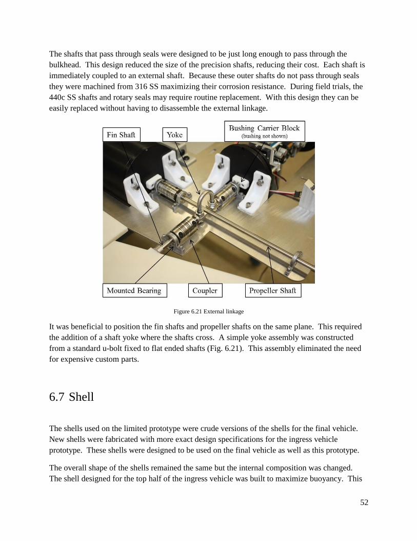
52
The shafts that pass through seals were designed to be just long enough to pass through the
bulkhead. This design reduced the size of the precision shafts, reducing their cost. Each shaft is
immediately coupled to an external shaft. Because these outer shafts do not pass through seals
they were machined from 316 SS maximizing their corrosion resistance. During field trials, the
440c SS shafts and rotary seals may require routine replacement. With this design they can be
easily replaced without having to disassemble the external linkage.
Figure 6.21 External linkage
It was beneficial to position the fin shafts and propeller shafts on the same plane. This required
the addition of a shaft yoke where the shafts cross. A simple yoke assembly was constructed
from a standard u-bolt fixed to flat ended shafts (Fig. 6.21). This assembly eliminated the need
for expensive custom parts.
6.7 Shell
The shells used on the limited prototype were crude versions of the shells for the final vehicle.
New shells were fabricated with more exact design specifications for the ingress vehicle
prototype. These shells were designed to be used on the final vehicle as well as this prototype.
The overall shape of the shells remained the same but the internal composition was changed.
The shell designed for the top half of the ingress vehicle was built to maximize buoyancy. This

53
reduced the amount of extra positive buoyancy that must be added to correctly balance the entire
vehicle. This half is only required to be strong enough to maintain shape for consistent
controlled flight. The bottom half shell is designed to maximize strength as it must deflect trawl
cables and may be subject to impacts from other trawl equipment. Weight was not a concern for
the bottom half because it must maintain a large bottom pressure while moored.
Both shells were made using a hybrid fiberglass and carbon fiber layup process. Layers of foam
were sandwiched between the layers of fiberglass. This foam provides additional strength and
buoyancy to the shell. Strips of carbon fiber were added to the shells along the edges and along
the vertical spines to increase rigidity and strength. The composition of the shells along each
edge is solid fiberglass and carbon fiber. This solid section of fiberglass and carbon fiber creates
a seal around the internal foam, preventing it from absorbing water and adding weight.
The top half shell was partitioned into three pieces: A single forward portion (roughly ¾ the
length of the vehicle), and an aft section split into starboard and port sections (Fig. 6.18).
Clearance between the shell and internal components was only critical in the aft section of the
vehicle. The forward section was designed to be thicker and more buoyant than the aft sections.
Each of the aft sections was fabricated to be very thin in order to provide maximum space for the
positioning of components inside this section of the vehicle. The bottom half shell was separated
into two pieces: the removable top cap, and the fixed base (Fig. 6.22).
Figure 6.22 Ingress vehicle prototype shells

54
6.8 General Assembly
In a large vehicle like the ingress vehicle, consideration was given to the placement of every
subsystem. Components were positioned so that many conditions could be met:
1. Correct weight and balance of vehicle
2. Ease of assembly
3. Easy accessibility to components that may require access in the field
4. Easy re-arming of buoyancy tubes and separation/attachment mechanism
The internal framing of this prototype was constructed from Aluminum T slotted extrusions.
These frames were nearly identical to those used in the limited prototype (Section 4.4). The
Aluminum T slotted framing allowed easy mounting of all subsystems and any additional weight
or buoyancy required for vehicle ballasting.
All water tight bottles containing electronic components were positioned in close proximity and
in the tail section of the vehicle. There are two identical motor bottles, a computer bottle and an
actuator bottle. Each of these four bottles is mounted to a removable plate. All additional
components of the propulsion and control surface systems are mounted to the plate as well (Fig.
6.23).
Figure 6.23 General layout for the ingress vehicle prototype
Overall assembly, bench testing and field repair were made more convenient with this mounting
scheme. During benchtop testing, all systems that require extensive testing are mounted to the
removable plate. This assembly is not as large and cumbersome as the full ingress vehicle.
These components represent the most likely cause of failure in the field. They will be easily

55
accessible in the tail section of the ingress vehicle, and if necessary the entire plate can be
removed from the vehicle to allow for comprehensive failure diagnosis and repair.
As noted in sections 6.1 and 6.3 both the skeg and the elevator assemblies may require size and
shape modification to optimize performance. These components are mounted to the plate so that
they are easily interchangeable with alternative designs. Additionally, for the ingress vehicle
prototype the communication array is mounted directly in front of the skeg. With this mounting
scheme a sail identical to that used on the egress vehicle could be used. This design reduced
difficulty routing cables from antennas (in the communication array) to the modems (in the
computer bottle).
Figure 6.24 Ingress prototype
7 Next Phase
There is still a significant amount of work required to complete the TRSMAUV project. The
ingress vehicle prototype is currently in the assembly phase. Upon full assembly of this
prototype, the vehicle will undergo a rigorous field testing phase. Field testing will validate the
flight ability of the ingress vehicle. Following confirmation that the ingress vehicle is capable of
efficient controlled flight, detail design work will be completed for the top-cap release of the
bottom half mooring mount. Additionally, detail design will be completed for mounting the
egress vehicle inside the ingress vehicle. This system will be fabricated and installed into the
ingress vehicle prototype. The final stage of the TRSMAUV design process will be full scale
mission testing that will include all stages of the mission profile.
56
8 References
[1] JG Dessureault, DJ Belliveau, SW Young, “Design and Tests of a Trawl-Resistant
Package for an Acoustic Doppler Current Profiler”, IEEE Journal of Oceanic
Engineering, 16(4):397-401, 1991.
[2] SC Cumbee, “A New Trawl-Resistant Bottom Mount to Support Hydrographic
Current Measurement Requirements”, OCEANS 2001, Honolulu, HI, 2001
[3] H Perkins, F de Strobel, and L Gualdesi, “The Barny Sentinel Trawl-Resistant ADCP
Bottom Mount: Design, Testing, and Application”, IEEE Journal of Oceanic
Engineering, 25(4):430-436, 2000.
[4] “Parker O-Ring Handbook”, Parker Hannifin Corporation, Cleveland, OH, 2007.
[5] Briggs, Robert C. Mechanical Design of a Self-Mooring Autonomous Underwater
Vehicle. Thesis. Virginia Polytechnic and State University, 2010
[6] Ball, Eddie, personal communication, November 17, 2015
[7] Portner, Stephen, personal communication, May 12, 2015
[8] Young, W.C., Roark’s Formulas for Stress & Strain, McGraw-Hill, Inc., New York, NY
1989.
[9] Mooring Systems, Inc, “Bottom Mount Systems for ADCPS”, August 2015. Online.
[Available] http://www.mooringsystems.com/mounts.htm