Mechanical Design of a Shape Memory Alloy Actuated ...engineering.nyu.edu › mechatronics ›...
34
1 Mechanical Design of a Shape Memory Alloy Actuated Prosthetic Hand Kathryn J. De Laurentis 1 and Constantinos Mavroidis 2 Robotics and Mechatronics Laboratory Department of Mechanical and Aerospace Engineering Rutgers University, The State University of New Jersey 98 Brett Rd, Piscataway, NJ, 08854-8058 Tel: 732 - 445 - 0732, Fax: 732 - 445 - 3124 E-mail: [email protected], [email protected] Webpage: http://cronos.rutgers.edu/~mavro/robot ABSTRACT This paper presents the mechanical design for a new five fingered, twenty degree-of- freedom dexterous hand patterned after human anatomy and actuated by Shape Memory Alloy artificial muscles. Two experimental prototypes of a finger, one fabricated by traditional means and another fabricated by rapid prototyping techniques, are described and used to evaluate the design. An important aspect of the Rapid Prototype technique used here is that this multi- articulated hand will be fabricated in one step, without requiring assembly, while maintaining its desired mobility. The use of Shape Memory Alloy actuators combined with the rapid fabrication of the non-assembly type hand, reduce considerably its weight and fabrication time. Therefore, the focus of this paper is the mechanical design of a dexterous hand that combines Rapid Proto- type techniques and smart actuators. The type of robotic hand described in this paper can be util- ized for applications requiring low weight, compactness, and dexterity such as prosthetic de- vices, space and planetary exploration. 1 Graduate Fellow 2 Associate Professor, Corresponding Author
Transcript of Mechanical Design of a Shape Memory Alloy Actuated ...engineering.nyu.edu › mechatronics ›...

1
Mechanical Design of a Shape Memory Alloy Actuated Prosthetic Hand
Kathryn J. De Laurentis1 and Constantinos Mavroidis2
Robotics and Mechatronics Laboratory
Department of Mechanical and Aerospace Engineering
Rutgers University, The State University of New Jersey
98 Brett Rd, Piscataway, NJ, 08854-8058
Tel: 732 - 445 - 0732, Fax: 732 - 445 - 3124
E-mail: [email protected], [email protected]
Webpage: http://cronos.rutgers.edu/~mavro/robot
ABSTRACT
This paper presents the mechanical design for a new five fingered, twenty degree-of-
freedom dexterous hand patterned after human anatomy and actuated by Shape Memory Alloy
artificial muscles. Two experimental prototypes of a finger, one fabricated by traditional means
and another fabricated by rapid prototyping techniques, are described and used to evaluate the
design. An important aspect of the Rapid Prototype technique used here is that this multi-
articulated hand will be fabricated in one step, without requiring assembly, while maintaining its
desired mobility. The use of Shape Memory Alloy actuators combined with the rapid fabrication
of the non-assembly type hand, reduce considerably its weight and fabrication time. Therefore,
the focus of this paper is the mechanical design of a dexterous hand that combines Rapid Proto-
type techniques and smart actuators. The type of robotic hand described in this paper can be util-
ized for applications requiring low weight, compactness, and dexterity such as prosthetic de-
vices, space and planetary exploration.
1 Graduate Fellow 2 Associate Professor, Corresponding Author
2
1 INTRODUCTION
It has been estimated that major amputations occur in one out of 300 individuals in the
United States, and that 23% of these are upper extremity amputations [33]. The primary causes
of upper extremity amputation include trauma, tumor, and congenital absence [17]. A large
number of amputees are candidates for prosthetic limb replacement that will restore a certain de-
gree of autonomy and improve their quality of life. In contrast to the dexterous manipulations
performed by computer-controlled robotic arms with many-degrees of freedom (DOF), human-
operated prosthetic arms function much as they did over a century ago, by single-jointed grasp-
ing [4]. This dichotomy underscores the urgent and unmet challenge of applying modern robotic
technologies to prosthetic devices [8]. Lighter, dexterous, powerful and quieter prostheses, im-
proved control of multiple degrees of freedom, along with sensory feedback, may greatly im-
prove the function of upper extremity prostheses, thereby enhancing productivity and options of
amputees and those with congenital limb absences [3].
In an effort to advance this technology, several unique and fascinating multi-fingered
multi-degree-of-freedom anthropomorphic hands have been developed over the past twenty
years. A good review of dexterous robotic hands can be found in [30, 31]. Some of the most
notable recent hands that are using state-of-the-art robotic technologies are the NTU Hand, the
DLR hand and the Robonaut hand [5, 18, 19, 20]. Existing dexterous artificial hands are primar-
ily using conventional means of actuation and fabrication, which result in high system complex-
ity and large weight, volume and fabrication time. In most cases, the actuators used do not have
a biomimetic behavior and this creates human interface control problems. Finally, the actuators
and transmission elements that are used in existing artificial hands are noisy and this creates dis-
comfort to the human operator.

3
The potential of using a new generation of small, smart material based, high powered,
biomimetic, artificial muscle actuators for robotic and biomedical applications is becoming in-
creasingly evident [6, 16]. These technologies include electro-magnetics, mechano-chemical
polymers, electro-chemo-mechanical polymers (conducting polymers), piezoelectric and mag-
neto-strictive materials, Shape Memory Alloys and polymers. Of these actuators, only Shape
Memory Alloys (SMA) have been used extensively in a vast number of applications including
robotics and medicine.
Shape Memory Alloys, such as Nickel-Titanium (Ni-Ti) wires, belong to a group of me-
tallic materials that demonstrate the ability to return to a predetermined shape or size when they
are subjected to heating. These properties allow the wire to be heated and cooled repeatedly to
provide a usable amount of force. This phenomenon, called the Shape Memory Effect (SME),
occurs when the material is heated above a certain transition temperature changing its crystalline
phase from Martensite to Austenite. Heating, and thus actuation, of an SMA wire is easily ac-
complished by applying a voltage drop across the wire causing current to flow through the mate-
rial, resulting in joule heating. Ease of actuation is not the only advantage of SMA actuators.
Other advantages are their incredibly small size, volume, and weight, their high force to weight
ratio, and their low cost. Their limitations include the need for a large length of wire to create
sizeable linear motion, the small amount of absolute force obtained from one SMA wire, a rela-
tively small bandwidth and low energy efficiency. A more detailed description of the SMA ef-
fect is presented in Section 2.
Since 1983, SMA artificial muscles have been used in micro-robotics. It was discovered,
that artificial muscle motion could be controlled and that their small size and displacement was
ideal for micro-robots, i.e. robots smaller than 1mm. In this context, SMA has been used in

4
many different robotic systems as micro-actuators [6, 13-15]. SMAs have been proposed as ac-
tuators for dexterous hands [34] and several of these works are briefly described here.
The most famous SMA actuated hand is the Hitachi Ltd. Hand [41]. This four-fingered
(three fingers and a thumb) hand weighs 4.49 kgs (9.9 lbs) and is 69.85 cm (27.5 inches) long,
which includes the forearm. It has a 1.995 kgf (4.4 lbf) load capacity. The fingers each have a
number of SMA 0.02 mm diameter wires that are set around the tube housings of its spring ac-
tuators. Each wrist axis (pitch and yaw) has four SMA 0.035 mm diameter wires set around pul-
leys and housed in the forearm. The joint travel speed is 90 degrees per second. A biomechanic
SMA hand that imitates the human hand in shape has been proposed in [25]. This is a five-
fingered hand utilizing four Flexinol NiTi wires per finger, which are connected on the upper and
lower part of the finger’s body on both sides. A Fingerspelling Hand, developed by Oaktree
Automation in 1989, presents data from a computer one character at a time using a fingerspelling
alphabet, which is read by the user placing their hands on the device [12]. The hand has a fore-
arm attached that houses the 108, 250 micron Flexinol wires acting in parallel, providing flexion
and extension, and abduction and adduction antagonistically. The mechanical design of a SMA
direct driven five finger robotic hand has been described in a recent US Patent [32].
Several SMA based actuator devices have been proposed specifically for use in robotic
and prosthetic hands. One device that uses SMA springs in a push-pull configuration has been
studied in [2]. Experiments were conducted in which two motor modules, each containing two
SMA coil-type springs, were placed inside a finger phalanx. This actuator was able to exert a
variable force at constant strain provided the SMA temperature does not exceed a limiting value.
A SMA actuated micro-joint of a dexterous micro-gripper has been proposed in [36]. The devel-
oped micro-joint, which has been integrated in the gripper's phalanx, consists of a five link two

5
degree of freedom planar mechanism that is actuated by two SMA wires. A novel SMA spring
based actuator for force-feedback hand masters has been proposed in [11]. Finally, a novel wrist
hand-orthosis system actuated by SMA artificial muscles has been presented in [21].
This paper presents the mechanical design for a new five fingered, twenty degree-of-
freedom dexterous hand, which is based on information obtained from the study of human anat-
omy and actuated by our SMA artificial muscles. The developed hand has potential to be used in
prosthetic and space robotic applications. The goal is to develop a biomimetic, ultra-lightweight
hand, with a high number of degrees of freedom that will be able to apply substantial forces.
Additional design requirements include fast fabrication times, noiseless operation and easy re-
placement of the components.
The lightweight requirement is achieved by using SMA artificial muscles as actuators of
the system joints and by eliminating all transmission elements such as gears, pulleys or springs.
The goal is to develop a hand that will weigh 1 kg. The dexterity requirement is achieved by de-
veloping a multi-degree of freedom hand with a high number of powered joints, following the
geometry, dimensions and actuation patterns of a human hand. Each joint has a large range of
motion that is achieved by attaching the SMA actuated tendons very close to the revolute joint
axes. The high force requirement is achieved by using a series of SMA wire bundles as artificial
muscles of the hand. The specific goal is to develop muscles that will apply forces of 50 N, re-
sulting in fingertip forces of 10 N. The operation of SMA muscles is noiseless. The SMA mus-
cles are placed outside the hand, in a forearm location. A modular design is proposed for the at-
tachment of the artificial muscles on the hand so that the procedure of muscle replacement is
very easy. This will allow the users of the hand, to easily replace the muscles if they break. It
will also permit us to exchange easily the artificial muscles and conduct experiments with other

6
types of smart material based artificial muscles. Finally, rapid prototyping techniques are used to
develop the structure of the hand. These techniques allow the fabrication of the hand in a very
short time as compared with conventional prototyping techniques. Because of the speed and
ease of this type of fabrication, replacing part or even a complete hand is quite feasible. Because
our rapid prototype assemblies use a lightweight material, the weight of the hand is reduced. A
novel characteristic of the rapidly prototyped hand is that its multi-finger, multi-jointed structure
is built in one step and no assembly is required.
It is important to note here that while the focus of this paper is purely mechanical design,
such aspects as actuator control, speed, and heat dissipation; inclusion of sensors; and thermal
isolation have not been neglected in the complete study of this problem. We have studied adap-
tive joint control algorithms for SMA actuated robotic systems [10]. Such algorithms, which al-
low accurate and fast joint control under varying payloads and configurations, will be used, in
the future, for the control of the Rutgers hand. In addition, for the specific prosthetic device con-
trol the concepts of the biomimetic myo-pneumatic controller will be utilized as specified in pa-
pers [1, 7]. Heat dissipation, thermal isolation and sensor addition are the subjects of on going
research at the Robotics and Mechatronics Laboratory at Rutgers University. While, all the
above mentioned issues are important and quite practical concerns, they are outside the scope of
this paper and are the subject of future papers.
Even though the applications of such a hand for robotics or prosthetics are different, the
mechanical design problem is similar. The intent of this paper is to explore the use of Rapid Pro-
totyping as a one-step, non-assembly, manufacturing process (not just a prototyping process) for
this dexterous hand that provides advantages over traditional forms of manufacturing. In addi-
tion, a nontraditional form of actuation is explored and used that in part dictates the design.

7
While there are many impressive hands, the purpose here is to improve the state-of-the-art. For
example, the very successful Hitachi Hand is not direct drive, whereas the hand described herein
is. There are other differences between the Hitachi Hand and the Rutgers Hand to be noted here:
the Rutgers Hand decreases the number of components and is a less complex design; the Rutgers
Hand does not use gears to increase the torque, rather it uses SMA bundles; and the Rutgers
Hand is lighter with more DOF. As mentioned previously, the focus of this paper is the me-
chanical design of a dexterous hand that combines Rapid Prototyping and smart actuators.
2 PRINCIPLES OF SMA BEHAVIOR
Shape Memory Alloys consist of a group of metallic materials that demonstrate the abil-
ity to return to some previously defined shape or size when subjected to the appropriate thermal
procedure. This phenomenon is known as the Shape Memory Effect (SME). The SME occurs
due to a temperature and stress dependent shift in the material’s crystalline structure between two
different phases called Martensite and Austenite. Martensite, the low temperature phase, is rela-
tively soft whereas Austenite, the high temperature phase, is relatively hard. In order to under-
stand this phenomenon, it is useful to consider the highly simplified two-dimensional representa-
tion of the material’s crystalline arrangement shown in Figure 1.
Each box represents a grain of material with its corresponding grain boundaries. The
grains form a heavily twinned structure, meaning they are oriented symmetrically across grain
boundaries. The twinned structure allows the internal lattice of individual grains to change while
still maintaining the same interface with adjacent grains. As a result, Shape Memory Alloy can
experience large macroscopic deformations while maintaining remarkable order within its micro-
scopic structure. For example, if a piece of SMA starts as Austenite (Figure 1a), the internal

8
atomic lattice of each grain is cubic creating grains with more or less right angles. If it is now
allowed to cool below the phase transition temperature, the crystalline structure changes to Mart-
ensite (Figure 1b) and the grains collapse to the structure represented by the diamonds. Note that
the grains lean in different directions for different layers. Now, if sufficient stress is applied, the
Martensitic structure represented in Figure 1b will start to yield and “de-twin” as the grains re-
orient such that they are all aligned in the same direction (Figure 1c).
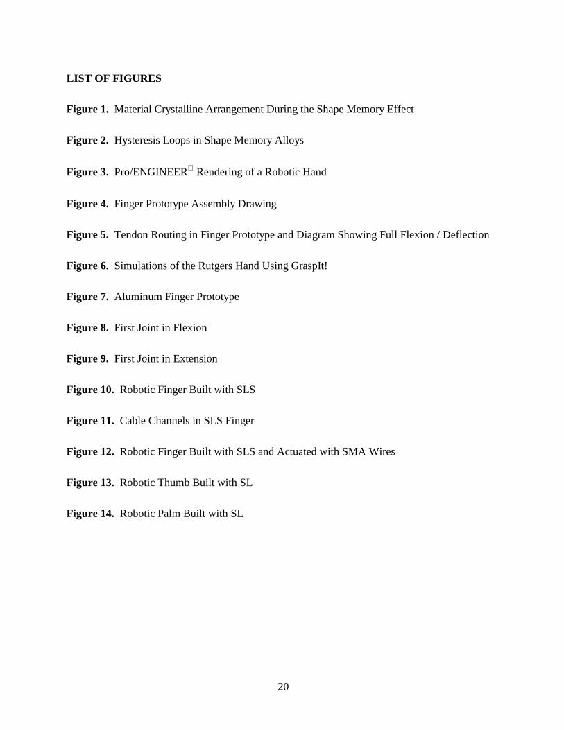
The change that occurs within a SMA’s crystalline structure during the SME is not a
thermodynamically reversible process. In other words there is energy dissipation due to internal
friction and creation of structural defects. As a result, a temperature hysteresis occurs which is
illustrated in Figure 2a. This temperature hysteresis translates directly into hysteresis in the
strain/temperature relationship (see Figure 2b). The hysteresis behavior makes it challenging to
develop modeling and control schemes for SMA actuators. Most Shape Memory Alloys have a
hysteresis loop width of 27.8 to 67.8°C (50 to 122 ºF), with the exception of some wide hystere-
sis alloys used for joining applications such as couplings. Additional information on SMA can
be found in [9, 23, 35, 37].
3 MECHANICAL DESIGN OF THE HAND
A five fingered, twenty degree-of-freedom dexterous prosthetic hand patterned after hu-
man anatomy and actuated by our artificial muscles is presented in this section. Figure 3 shows
the conceptual design of the hand. Figure 4 shows the detailed mechanical design of one finger.
The links of the first prototype are made of aluminum pipe, the outer diameter measuring 0.246
cm (5/8-inch). The distal and middle links are each 2.54 cm (one-inch) in length and the proxi-
mal link is 3.81 cm (1 ½ inches) long. Custom designed pivot brackets connect the links. These
pivot brackets are attached inside the distal and middle links allowing revolute movement of the
9
following link about the revolute pin. These brackets also serve as channels for routing the ca-
bles through the fingers. The proximal link is attached to the palm with a ball rod end joint that
allows abduction and adduction of the fingers, as well as flexion and extension. The maximum
deflection for each joint is approximately 80° in each direction. The range of motion for the rod-
end joints for the four fingers is 90° in flexion and extension, and +10° for lateral movement.
The ball and socket joint for the thumb has +30° deflection in all directions. The total hand (four
fingers, thumb, palm and shaft) weight is estimated that it will be less than 1.36 kg.
The joints of the artificial hand are actuated by a set of cables or "tendons" routed within
the structure of the finger. This is done to protect the cable and allow for an external synthetic
covering to be placed over the exoskeleton. Thin braided Teflon coated tendons, are connected
distal to each joint (forward of the axis), and run through the pivot brackets along the length of
the finger. The pivot bracket design is such that different routing schemes can be accomplished.
Figure 5 shows one routing scheme of the tendons within the finger. With this scheme all the
cables run on top of the joints except for the last joint closest to the palm (and the joint where the
cable is attached). By routing the tendons above these successive joints, any reaction to the force
applied to the desired joint only cause the successive joints to lock in extension. Additionally,
routing can be done so joints are coupled thus decreasing the degrees-of-freedom. The distal and
middle links are coupled so that actuation of the distal link also moves the middle link similar to
the natural movement of a human finger. This coupling is done by running the cables for the dis-
tal joint through the connecting channel of the middle joint, so that when the distal joint is actu-
ated the middle follows. This also reduces the number of artificial muscles required and the
power consumed. Confirmation of the effectiveness and pertinence to the desired application of
both of these routing schemes is presently being undertaken. Figure 5 also shows the required

10
displacement of the SMA to achieve a full 80° range of motion of the joints, which has been suc-
cessfully tested.
The cables run through the middle of the wrist spherical joint and are attached to artificial
muscles, placed parallel to each other in a position similar to the position of the radius and ulna
in a human arm. For each finger, there are two artificial muscle bundles attached to the distal
joint and two to the proximal joint: one muscle bundle for flexion and one for the recovery force
needed to reposition the joint to its original configuration. The abduction and adduction motions
of the proximal joint are passive. Because a ball rod end joint is used for the proximal joint,
slight side-to-side movement occurs when the cables from the proximal joint are pulled. Three
artificial muscle bundles at the thumb ball and socket joint provide the extension/flexion and ab-
duction/adduction of this joint. In our previous work we have successfully achieved actuation of
a ball and socket joint using three SMA artificial muscles placed symmetrically in an antagonis-
tic actuation scheme [29]. The artificial muscles consist of bundles of SMA wires that are fabri-
cated using the design considerations and techniques described in [24].
Simulations using the software package GraspIt!, from Columbia University, have been
performed to test the grasping capabilities of the hand. GraspIt! is a versatile three-dimensional
grasping simulator that allows a user to perform grasps with an artificial hand model and visual-
ize the space of forces and torques that can be applied by each grasp [26, 27], which is directed
by the hand’s geometry and kinematics, and the CAD file information. This simulator is cur-
rently being used to test the Rutgers hand design for real-time collision detection, workspace
analysis, and design evaluation based on grasping capabilities. Figure 6 illustrates the Rutgers
hand in the simulator grasping a mug. Initial testing of the hand shows that all links are capable

11
of grasping the object. This verifies that the range of motion of the joints and finger link lengths
are adequate, with few collisions detected.
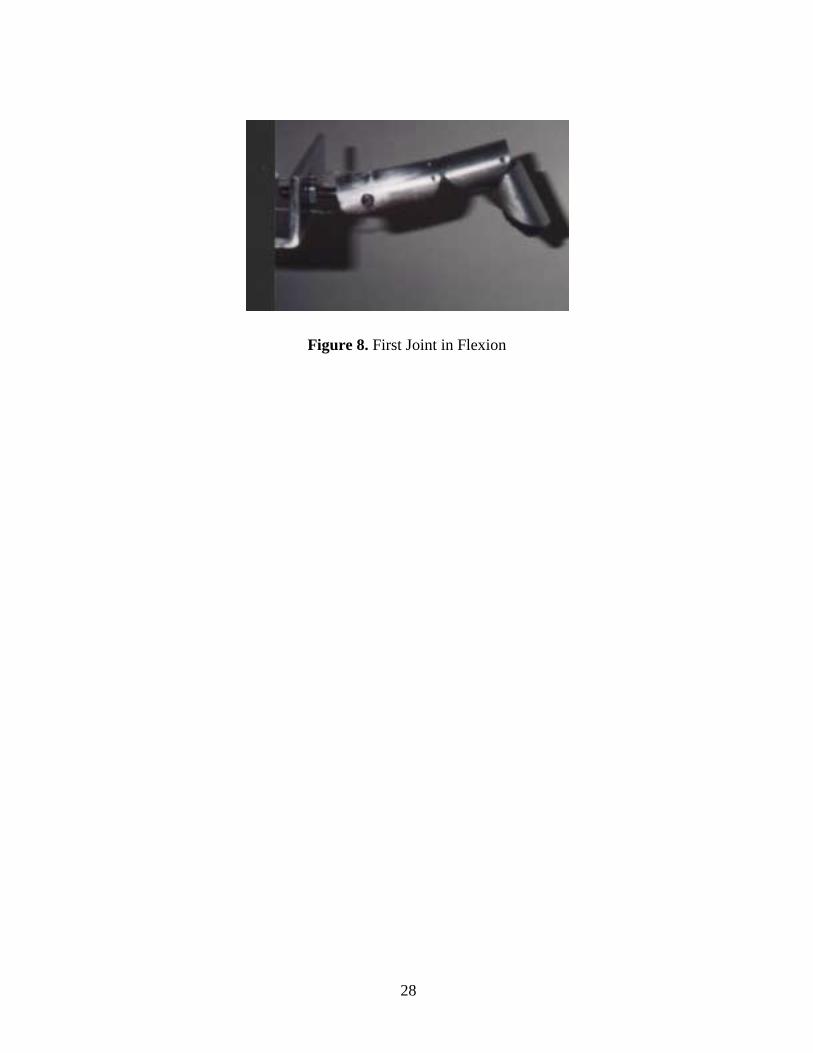
Figure 7 shows the aluminum four degree-of-freedom SMA actuated finger prototype
that has been built to test the mechanical design of the hand and the SMA bundle actuators de-
scribed. The palm currently consists of two 7.67 cm x 7.67 cm aluminum channels placed to-
gether for mounting of the finger. The forearm shaft serves as the mounting brace for the SMAs.
The final assembly weighs 0.248 kg and the finger weighs 0.363 kg. The photographs in Figures
8 and 9 show the resulting uncoupled deflections from the first joint articulation. The results of
these tests showed that while the SMA articulated the joint in full deflection of either extension
or flexion, it was difficult to have the action performed consecutively in both directions. Though
the SMAs are placed and perform in an antagonistic manner, they had to be adjusted to perform
either motion precisely. The SMAs used for these tests were one bundle per joint of two linked
250 µm diameter wires. Recent tests of new SMA bundles have improved these results and
added increased force capabilities for the bundles [28]. These new actuators are capable of pro-
viding a force of 53.4 N (at a power consumption of 14.5 W), which translates to at least a 6.67
N fingertip force. For further experiments, the successive joints would be tested first individu-
ally for maximum deflection, then various configurations and combinations of fingers, and fi-
nally, testing would be performed on the entire hand with full articulation.
4 HAND FABRICATION USING RAPID PROTOTYPING
In addition to the aluminum prototype, a rapidly prototyped robotic hand (Figure 3) with
five fingers and a palm has been designed. The fingers are composed of three cylindrical links
connected by two revolute joints. Each of the fingers is to be attached to the palm section by

12
modified spherical joints. This complex system is currently being fabricated; entirely con-
structed as one non-assembly type mechanism using a Rapid Prototyping (RP) technique. Thus
far, two Rapid Prototyping techniques, StereoLithography (SL) and Selective Laser Sintering
(SLS) have been used for the rapid fabrication of several fingers, a thumb, and palm.
4.1 Rapid Prototyping Techniques
Conventional manufacturing, such as CNC machining, fabricates a part by selectively
taking away material from a work piece. However, Rapid Prototyping is a fabrication technique
where three-dimensional solid models are constructed layer upon layer by the fusion of material
under computer control. This process generally consists of a substance, such as fluids, waxes,
powders or laminates, which serves as the basis for model construction as well as sophisticated
computer-automated equipment to control the processing techniques such as deposition, sinter-
ing, lasing, etc. Also referred to as Solid Freeform Fabrication, Rapid Prototyping complements
existing conventional manufacturing methods of material removing and forming. It is widely
used for the rapid fabrication of physical prototypes of functional parts, patterns for molds,
medical prototypes such as implants, bones and consumer products. Its main advantage is early
verification of product designs. Through quick design and error elimination, Rapidly Prototyped
parts show great cost savings over traditionally prototyped parts in the total product life cycle
[38].
StereoLithography (SL) is a three-dimensional electro-mechanical building process,
which produces a solid plastic model. In this process, a low-powered ultraviolet (UV) laser
traces two-dimensional cross-sections on the surface of a photosensitive liquid plastic (resin).
Successive 2-D slices are cured directly onto the previous layer as the entire part is built from
bottom to top. The Department of Mechanical and Aerospace Engineering of Rutgers University

13
is equipped with a Stereolithography 190 machine from 3D Systems, of Valencia, CA. Avail-
able basis materials for this machine include photo-polymer resin epoxies with various physical
properties. (Material data sheets for Cibatool® SL 5170 resin used here can be obtained from the
developers: Ciba-Geigy Corporation, Formulated Systems Group, of East Lansing, MI.)
Selective Laser Sintering (SLS) is a three-dimensional building process based on the sin-
tering (heating and fusing) of a metallic or non-metallic powder by a laser. The fabrication of
prototype parts used in the present investigations was through a professional Rapid Prototyping
service provider for SLS manufacturing. The machine used is the Selective Laser Sintering Sin-
terstation 2000 of DTM Corporation of Austin, TX.
The Rapid Prototyping process begins with the development of Computer Aided Designs
(CAD) solid models. The solid models for this project were made using Pro/ENGINEER and
are shown here along with the actual prototype. Upon completion of the solid model, it is ex-
ported to the RP machine for fabrication.
4.2 Rapidly Prototyped Robotic Hand
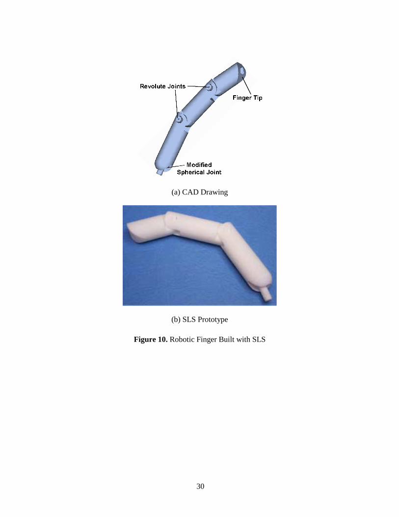
The initial step toward fabricating a robotic hand is the successful fabrication of the
joints. Additionally, an important design consideration in this robotic hand prototype is to have
the same range of motion and similarity in size to that of an average human hand. The latter
guiding design feature necessitated the use of modified joint designs to partially restrict some of
the degrees of freedom. The spherical joint that meets the fingers with the palm is one such joint
(Figure 10). The non-assembly type finger prototype shown here was built using the SLS proc-
ess, with a glass-filled nylon material, and produced joints that exhibit good mobility through the
desired ranges of motion. One of the challenges of using Rapid Prototyping in non-assembly

14
hand fabrication is the assurance of proper joint clearances. This SLS finger prototype is an ex-
ample of this as the clearances are such that there is additional movement in the joints than de-
sired. However, this movement is minimal still allowing very good finger mobility. Later proto-
types eliminated this problem.
Additionally, no lubrication is needed due to the techniques used here for building the
non-assembly type joints. Though the joints move freely with little friction, it is possible that
over time some wearing may occur (metal inserts may be necessary in future joints). To date,
this is not a problem and no maintenance is required. The lifetime of the RP hand material is ex-
pected to be similar to that of traditional plastic parts.
Actuation of the robotic hand is to be achieved through a combination of cables (tendons)
and Shape Memory Alloy artificial muscle wires. The SMA wires to be used in this design have
a wire diameter of approximately 150 microns (0.006"). The cables are connected close to the
pivot points of the revolute joints and run through the incorporated “pathways” (Figure 11)
within the length of the fingers. The cables are crimped to SMA muscle wires proximal to the
palm. It is necessary to run the cables through the hand rather than the SMAs themselves as the
activation temperature of the SMA is 70° - 90°C and the melting temperature of the SL material
is 85°C. (The melting temperature is not a consideration with the SLS material as its melting
temperature is 185°C.) The use of SMA wires will be the first attempt at actuating a Rapidly
Prototyped system at Rutgers University.
Figure 11 shows a cutaway view of the channels within the finger for routing of the ca-
bles used for actuation. These pathways, 0.254 cm in diameter, were designed to guide the ca-
bles through the finger links so as to decrease stress on the cables while maintaining the required
tension. One channel through the middle link appears in a diagonal pattern, as seen from this

15
side view, for the above-mentioned purpose. In addition, the cables intended for flexion and ex-
tension of the distal link travel over top of the revolute joint between the middle and proximal
links. The channels through the proximal link fan out around the ball and socket (which could be
seen from a dorsal view). Two cable pathways, one for flexion and one for extension of the
modified spherical joint, run through the socket on the palmar and dorsal sides to allow for 90°
rotation during actuation. Currently, abduction and adduction movement at the finger spherical
joint is passive. This is due to the modified spherical joints natural side to side motion when the
cables from the proximal joint are pulled.
Figure 12 shows the SLS fabricated finger with the tendons (cables) attached in a post-
fabrication phase. As in the previous SLS constructions, the joints fully reach the designed range
of motion. Additionally, all the pathways and cable assembly holes were clear of material. The
Selective Laser Sintering process successfully fabricated this multi-joint, multi-degree-of-
freedom robotic finger.
Other fabricated hand parts were done with the SL technique (SLA 190 with Cibatool®
SL 5170 resin) and are shown in Figures 13 and 14. The thumb design (Figure 13) has been
modified to a two link, two joint assembly to more closely resemble the size and “appearance” of
the human thumb. Additionally, slots for sensors have been incorportated for strain gauges to
measure all fingertip forces and the palmar grasp force. The position of each link will be
measured with Hall effect magnetic position sensors placed in the links. Figure 14 shows the
palm design and fabricated part. The palm is hollow to allow for passage of cables and sensors.
Because fabrication of the separate structures of the robotic hand has been successful, the entire
hand can now be built as one non-assembly prototype. Additional information on the application
of rapid prototyping in the fabrication of robotic systems can be found in [39, 40].

16
5 CONCLUSIONS
The mechanical design of a dexterous hand that combines Rapid Prototyping techniques
and smart actuators was presented. The concept of actuation for one finger with one cable rout-
ing scheme was successfully tested with the aluminum finger prototype. Rapid prototyping
techniques have also been used to develop prototypes of a finger. Additionally, the mechanical
design grasping ability for the Rapid Prototype hand has been confirmed. The prototype experi-
mentation and the design finalization of the robotic hand described here are ongoing projects.
Future work will involve the performance of closed loop computer control experiments with
various control schemes such as adaptive and non-linear control. Electrical and thermal insula-
tion of the actuators in the hand and electrical consumption of the prototype are also subjects of
future work.
6 ACKNOWLEDGMENTS
This work is supported by a CAREER grant (DMI-9984051) from the National Science
Foundation. Support from the Center for Advanced Information Processing (CAIP) and the Cen-
ter for Computational Design of Rutgers University are gratefully acknowledged. Kathryn De-
Laurentis is supported by a National Science Foundation Graduate Research Fellowship. The
assistance provided by Charles Pfeiffer in the mechanical design of the aluminum finger and by
Jey Won in the fabrication of the SLS finger are acknowledged and appreciated. Andrew Miller
and Peter Allen provided a copy of the software GraspIt!. A PCT International patent applica-
tion has been filed by Rutgers University for the devices presented in this paper [22].

17
7 REFERENCES
[1] R. Abboudi, C. Glass, N. A. Newby and W. Craelius, A Biomimetic Controller for a Dexterous Hand, Proceedings of the 1999 IEEE Transactions on Rehabilitation Engi-neering, 7 (1999), 121-129.
[2] M. Bergamasco, F. Salsedo and P. Dario, Shape Memory Alloy Micromotors for Direct-Drive Actuation of Dexterous Artificial Hands, Sensors and Actuators, 17 (1989), 115-119.
[3] J. N. Billock, Current Challenges in The Practice of Upper-Limb Prosthetics, Report for a Research Planning Conference on Prosthetic and Orthotic Research for the 21st Century, National Institute of Child Health and Human Development, 1992, pp. 109-102.
[4] J. H. Bowkler and Michael J. W., Atlas of Limb Prosthetics, St Louis: Mosby Year Book, 1992.
[5] J. Butterfass, G. Hirzinger, S. Knoch and H. Liu, DLR’s Multisensory Articulated Hand, Part I: Hard- and Software Architecture, Proceedings of the 1998 IEEE International Conference on Robotics and Automation, Leuven, Belgium, 1998, pp. 2081-2086.
[6] D. G. Caldwell and P. M. Taylor, Artificial Muscles as Robotic Actuators, Proceedings of the IFAC Robot Control Conference (Syroco 88), Karlsrue, Germany, 1998 pp. 401-406.
[7] W. Craelius, N. A. Newby and R. Abboudi, Control of a Multi-Fingered Prosthetic Hand, Proceedings of the Sixth International Conference on Rehabilitation Robotics, (ICORR ’99) Stanford University, 1999, pp. 255-260.
[8] A. Davalli, R. Sacchetti, and H. Schmidl, Multifunctional Prosthetic-Robotics Systems. When?, Proceedings of the 1993 IEEE International Conference on Systems, Man and Cybernetics, Le Touquet, France, 1993, pp. 531-533.
[9] T. W. Duerig (Editor), Engineering Aspects of Shape Memory Alloys, Butterworth-Heinemann, 1990.
[10] Y. Eren, C. Mavroidis and J. Nikitczuk, B-Spline Based Adaptive Control of Shape Memory Alloy Actuated Robotic Systems, submitted for publication in the Proceedings of the 2002 IEEE International Conference on Robotics and Automation, Washington D.C., May 2002.
[11] M. A. Gharaybeh and G. C. Burdea, Investigation of a Shape Memory Alloy Actuator for Dexterous Force-Feedback Masters, Advanced Robotics, 9 (1995), 317-329.
[12] R. G. Gilbertson, Muscle Wires Project Book, California: Mondotronics, Inc., 1994, 3rd Edition.
[13] D. Grant, Shape Memory Alloy Actuator With an Application to a Robotic Eye, Master Thesis, Department of Electrical Engineering, McGill University, 1995.

18
[14] I. Hunter, S. Lafontaine, J. Hollerbach and P. Hunter, "Fast Reversible NiTi Fibers for Use in Microrobotics", Proceedings of the 1991 IEEE Micro Electro Mechanical Systems Conference - MEMS 91, pp 166-170.
[15] K. Kuribayashi, A New Actuator of a Joint Mechanism Using TiNi Alloy Wire, Interna-tional Journal of Robotics Research, 4 (1986), pp. 47-58.
[16] R. Kornbluh, R. Pelrine, J. Eckerle and J. Joseph, Electrostrictive Polymer Artificial Muscle Actuators, Proceedings of the 1998 IEEE International Conference on Robotics and Automation, Leuven, Belgium, 1998.
[17] D. W. Lamb, State of the Art in Upper-Limb Prosthetics, Journal of Hand Therapy, 6 (1993), 1-8.
[18] L. Lin and H. Huang, NTU Hand: A New Design of Dexterous Hands, Journal of Me-chanical Design, Transactions of the ASME, 120 (1998), 282-292.
[19] H. Liu, P. Meusel, J. Butterfass and G. Hirzinger, DLR’s Multisensory Articulated Hand, Part II: The Parallel Torque / Position Control System, Proceedings of the 1998 IEEE In-ternational Conference on Robotics and Automation, Leuven, Belgium, 1998, pp. 2087-2093.
[20] C. S. Lovchik and M. A. Diftler, The Robonaut Hand: A Dexterous Robot Hand for Space, Proceedings of the 1999 IEEE Int. Conference on Robotics and Automation, De-troit, MI, 1999, pp. 907-912.
[21] J. E. Makaran, D. K. Dittmer, R. O. Buchal and D. E. MacArthur, The SMARTTM Wrist-Hand Orthosis (WHO) for Quadriplegic Patients, Journal of Prosthetics and Orthotics, 5 (1992), 73-76.
[22] C. Mavroidis, K. J. DeLaurentis, C. Pfeiffer and M. Mosley, Prosthetic, Orthotic, and Other Rehabilitative Robotic Assistive Devices Actuated by Smart Materials, Rutgers Docket Number 99-0001; PCT International patent application filed by Rutgers Univer-sity, September 1999.
[23] C. Mavroidis, C. Pfeiffer and M. Mosley, Conventional Actuators, Shape Memory Alloys and Electrorheological Fluids, Automation, Miniature Robotics and Sensors for Non-Destructive Testing and Evaluation, Y. Bar-Cohen Editor, The American Society for Nondestructive Testing, Inc. (ASNT), 2000, pp. 189-214.
[24] M. Mosley and C. Mavroidis, Design and Control of a Shape Memory Alloy Wire Bun-dle Actuator, Proceedings of the 2000 ASME Mechanisms and Robotics Conference, Bal-timore MD, September 10-13, 2000. Paper DETC2000/MECH-14157.
[25] I. Mihalcz, E. I. Zudor, V. Csibi and P. Baranyi, A Biomechanic Robot Hand Using SMA, Proceedings of the Tenth World Congress on the Theory of Machines and Mecha-nisms, Oulu, Finland, 1999, pp. 1835-1840.
[26] A. T. Miller and P. K. Allen, GraspIt!: A Versatile Simulator for Grasp Analysis, Pro-ceedings of the International Robotics Symposium, Montreal, Canada, 2000.

19
[27] A. T. Miller and P. K. Allen, Examples of 3D Grasp Quality Computations, Proceedings of the 1999 IEEE International Conference on Robotics and Automation, 1999, pp. 1240-1246.
[28] J. Nikitczuk, Control, Design, and Testing of Shape Memory Alloy Actuators, Technical report for the New Jersey Space Grant Consortium, August 2001.
[29] C. Pfeiffer, K. J. DeLaurentis and C. Mavroidis, Shape Memory Alloy Actuated Robot Prostheses: Initial Experiments, Proceedings of the 1999 IEEE International Conference on Robotics and Automation, Detroit, MI, 1999, pp. 2385-2391.
[30] J. L. Pons, R. Ceres and F. Pfeiffer, Multifingered Dexterous Robotic Hand Design and Control: A Review, Robotica, 17 (1999), 661-674.
[31] M. E. Rosheim, Robot Evolution: The Development of Anthrobotics, New York: John Wiley & Sons, Inc., 1994.
[32] J. A. Rush, Memory Wire Robotic Hand, United States Patent Number 5,647,723, Date July 15, 1997.
[33] H.A. Rusk, Rehabilitation Medicine, St. Louis: CV Mosby, 1977.
[34] A. B. Soares, H. M. Brash and D. Gow, The Application of SMA in the Design of Pros-thetic Devices, Proceedings of the 2nd International Conference on Shape Memory and Superelastic Technologies, Pacific Grove, CA, 1997, pp. 257-262.
[35] Toki Corporation, Biometal Guidebook, Tokyo, Japan, 1987.
[36] N. Troisfontaine, P. Bidaud and G. Morel, A New Inter-Phalangeal Actuator for Dexter-ous Mirco-Grippers, Proceedings of the 1997 IEEE International Conference on Robotics and Automation, Albuquerque, New Mexico, 1997, pp. 1773-1778.
[37] T. Waram, Actuator Design Using Shape Memory Alloys, Mondotronics, Inc., 1993.
[38] T. Wohlers, Rapid Prototyping and Tooling State of the Industry: 1999 Worldwide Pro-gress Report, Wohlers Associates, 1999.
[39] J. Won, K. DeLaurentis and C. Mavroidis, Fabrication of a Robotic Hand Using Rapid Prototyping, Proceedings of the 2000 ASME Mechanisms and Robotics Conference, Bal-timore MD, September 10-13, 2000. Paper DETC2000/MECH-14203.
[40] J. Won, K. DeLaurentis and C. Mavroidis, Rapid Prototyping of Robotic Systems, Pro-ceedings of the 2000 IEEE International Conference on Robotics and Automation, April 24-28 2000, San Francisco, CA, pp. 3077-3082.
[41] N. Yoshiyuki et al., Hitashi's Robot Hand, Robotics Age, 6 (1984), 18-20.
20
LIST OF FIGURES
Figure 1. Material Crystalline Arrangement During the Shape Memory Effect
Figure 2. Hysteresis Loops in Shape Memory Alloys
Figure 3. Pro/ENGINEER Rendering of a Robotic Hand
Figure 4. Finger Prototype Assembly Drawing
Figure 5. Tendon Routing in Finger Prototype and Diagram Showing Full Flexion / Deflection
Figure 6. Simulations of the Rutgers Hand Using GraspIt!
Figure 7. Aluminum Finger Prototype
Figure 8. First Joint in Flexion
Figure 9. First Joint in Extension
Figure 10. Robotic Finger Built with SLS
Figure 11. Cable Channels in SLS Finger
Figure 12. Robotic Finger Built with SLS and Actuated with SMA Wires
Figure 13. Robotic Thumb Built with SL
Figure 14. Robotic Palm Built with SL

21
Figure 1. Material Crystalline Arrangement During the Shape Memory Effect
22
Figure 2. Hysteresis Loops in Shape Memory Alloys

23
Figure 3. Pro/ENGINEER Rendering of a Robotic Hand

24
Figure 4. Finger Prototype Assembly Drawing

25
Figure 5. Tendon Routing in Finger Prototype and Diagram Showing Full Flexion / Deflection

26
Figure 6. Simulations of the Rutgers Hand Using GraspIt!

27
Figure 7. Aluminum Finger Prototype
28
Figure 8. First Joint in Flexion

29
Figure 9. First Joint in Extension
30
(a) CAD Drawing
(b) SLS Prototype
Figure 10. Robotic Finger Built with SLS

31
Figure 11. Cable Channels in SLS Finger

32
Figure 12. Robotic Finger Built with SLS and Actuated with SMA Wires

33
(a) CAD Drawing
(b) SL Prototype
Figure 13. Robotic Thumb Built with SL

34
(a) CAD Drawing
(b) SL Prototype
Figure 14. Robotic Palm Built with SL