Mechanical Design Lab 1 - Penn Engineering - Welcome to …robo2008/labs/MechanicalDesign1.pdf ·...
11
SAAST Robotics Program 2008 Mechanical Design Lab 1 Mechanism Synthesis, Prototyping and the World’s Strongest Truck In this lab you will be introduced to 3 different linkage mechanisms and prototyping techniques such as foam core mock-ups and laser cutting of acrylic parts. You will design and build a “truck” to transport as much payload as possible up an inclined plane. Read the entire lab first before starting. Part 1: Mechanism Synthesis* An assembly of n links has a total of 3n degrees of freedom before they are joined to form a mechanism. The act of connecting the links with joints results in the loss of degrees of freedom for the total system. Pin (or revolute) joints and slider joints both only allow for one degree of relative motion for the links that they join. Therefore, Gruebler has derived the following formula to determine the number of degrees of freedom for a mechanism that is comprised of members attached with pin and/or slider joints: ) ( 2 ) 1 ( 3 # 2 1 j j n DOF + ⋅ - - ⋅ = where: n = number of links/members j 1 = number of pin (revolute) joints j 2 = number of slider joints For each mechanism/linkage identify: • how many members comprise the mechanism (don’t forget ground) • the types of joints present • the number of degrees of freedom Note: The number of pin joints at a common connection is j 1 = m -1, where m is the number of links joined by a single revolute joint.
Transcript of Mechanical Design Lab 1 - Penn Engineering - Welcome to …robo2008/labs/MechanicalDesign1.pdf ·...

SAAST Robotics Program 2008
Mechanical Design Lab 1
Mechanism Synthesis, Prototyping and the World’s Strongest Truck
In this lab you will be introduced to 3 different linkage mechanisms and prototyping
techniques such as foam core mock-ups and laser cutting of acrylic parts. You will
design and build a “truck” to transport as much payload as possible up an inclined plane.
Read the entire lab first before starting.
Part 1: Mechanism Synthesis*
An assembly of n links has a total of 3n degrees of freedom before they are joined to
form a mechanism. The act of connecting the links with joints results in the loss of
degrees of freedom for the total system. Pin (or revolute) joints and slider joints both
only allow for one degree of relative motion for the links that they join. Therefore,
Gruebler has derived the following formula to determine the number of degrees of
freedom for a mechanism that is comprised of members attached with pin and/or slider
joints:
)(2)1(3# 21 jjnDOF +⋅−−⋅=
where: n = number of links/members
j1 = number of pin (revolute) joints
j2 = number of slider joints
For each mechanism/linkage identify:
• how many members comprise the mechanism (don’t forget ground)
• the types of joints present
• the number of degrees of freedom
Note: The number of pin joints at a common connection is j1 = m -1, where m is the
number of links joined by a single revolute joint.
In the report: Include completed Mechanism Synthesis Worksheets.
* Reference:
• Erdman, A., Sandor, G. Mechanism Design – Analysis and Synthesis, Volume 1,
2nd
ed. Prentice-Hall, 1994, Englewood Cliffs, NJ.
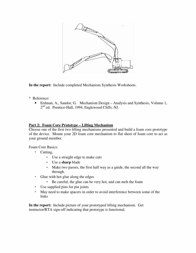
Part 2: Foam Core Prototype – Lifting Mechanism
Choose one of the first two lifting mechanisms presented and build a foam core prototype
of the device. Mount your 2D foam core mechanism to flat sheet of foam core to act as
your ground member.
Foam Core Basics:
• Cutting,
– Use a straight edge to make cuts
– Use a sharp blade
– Make two passes, the first half way as a guide, the second all the way
through.
• Glue with hot glue along the edges
– Be careful, the glue can be very hot, and can melt the foam
• Use supplied pins for pin joints
• May need to make spacers in order to avoid interference between some of the
links
In the report: Include picture of your prototyped lifting mechanism. Get
instructor/RTA sign-off indicating that prototype is functional.
Part 3: WORLD’S STRONGEST TRUCK
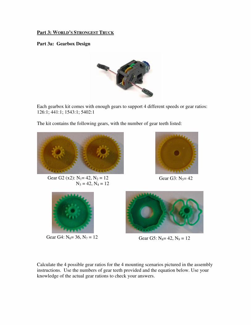
Part 3a: Gearbox Design
Each gearbox kit comes with enough gears to support 4 different speeds or gear ratios:
126:1; 441:1; 1543:1; 5402:1
The kit contains the following gears, with the number of gear teeth listed:
Calculate the 4 possible gear ratios for the 4 mounting scenarios pictured in the assembly
instructions. Use the numbers of gear teeth provided and the equation below. Use your
knowledge of the actual gear rations to check your answers.
Gear G4: N6= 36, N7 = 12
Gear G2 (x2): N1= 42, N2 = 12
N3 = 42, N4 = 12 Gear G3: N5= 42
Gear G5: N8= 42, N9 = 12

gearsdriveronteethofnumbersofproduct
gearsdrivenonteethofnumbersofproductRatioGear
driven
driver==
ω
ω
A worm gear is used to change the direction of motion of output shaft from the motor.
Assume that the worm gear is rotating at ωin = ωdriver = 7000 revolutions per minute
(rpm). Calculate the speed in rpms for the output shaft of the gear box for all 4 cases.
Choose the appropriate gear ratio for this application and assemble the gearbox.
In the report:
Include completed Gear Ration Calculations Worksheet for each gear ratio case. Identify
the drive and driven gears – i.e. driven gear: G3-N5. Show all calculations used to
determine gear ratios and output shaft speeds. Also, list choice for gear ratio and explain
the reasons for your choice.
Part 3b: Chassis and Wheel Design
Using the 0.25” thick acrylic material, design a truck bed that has inside dimensions of 5”
x 3” and walls that are 2” high. Be sure to include mounting holes for gearbox on bottom
of truck bed and one for a “caster” that will be used as a third support for your truck.
You need to include mounting hole for on/off switch on one side of truck bed. The
switch requires a ¼” diameter hole. Include through hole on one wall where wires to
battery can be routed.
Choose the appropriate wheel diameter for this application and explain your choice.
Design the wheel for high traction when operating on the test platform – hint: completely
circular wheels may slip. Include mounting holes in wheels so that you can mount it to
drive shaft coming from gearbox. Choose length of caster to in conjunction with wheel
diameter choice.
Optional: You can alter the supplied drive shaft or design new ones to mount to the
wheels if you so desire. You can use the supplied connectors or mount directly to the
drive shaft.
Use the laser cutter to manufacture the parts.
In the report:
Include print-out of CAD file of part designs used for laser cutting. Describe reasons for
choice of wheel diameter.
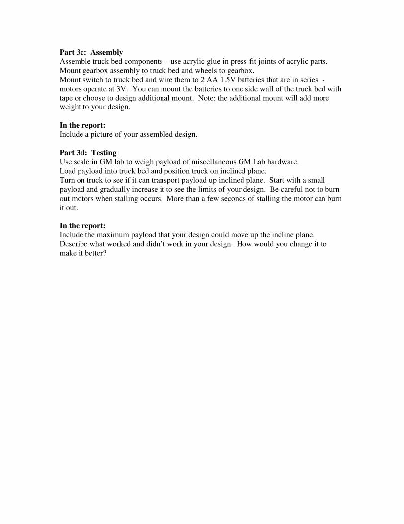
Part 3c: Assembly
Assemble truck bed components – use acrylic glue in press-fit joints of acrylic parts.
Mount gearbox assembly to truck bed and wheels to gearbox.
Mount switch to truck bed and wire them to 2 AA 1.5V batteries that are in series -
motors operate at 3V. You can mount the batteries to one side wall of the truck bed with
tape or choose to design additional mount. Note: the additional mount will add more
weight to your design.
In the report:
Include a picture of your assembled design.
Part 3d: Testing
Use scale in GM lab to weigh payload of miscellaneous GM Lab hardware.
Load payload into truck bed and position truck on inclined plane.
Turn on truck to see if it can transport payload up inclined plane. Start with a small
payload and gradually increase it to see the limits of your design. Be careful not to burn
out motors when stalling occurs. More than a few seconds of stalling the motor can burn
it out.
In the report:
Include the maximum payload that your design could move up the incline plane.
Describe what worked and didn’t work in your design. How would you change it to
make it better?

Sample Component Design Schematic:
Wheels
Caster
Truck Bed Bottom
Side Wall
Side Wall
Side Wall
Side Wall

Lab Worksheets

Name: ______________________________
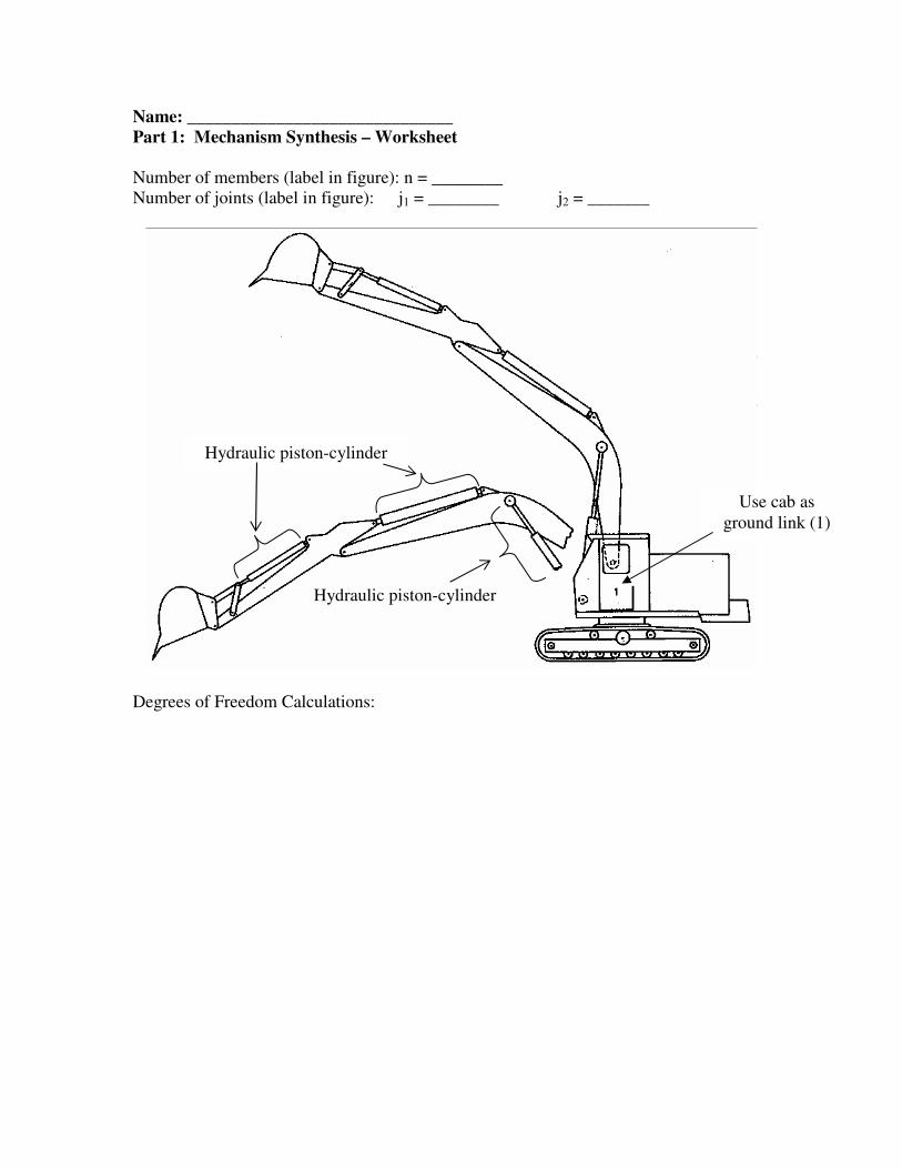
Part 1: Mechanism Synthesis – Worksheet
Number of members (label in figure): n = ________
Number of joints (label in figure): j1 = ________ j2 = _______
Degrees of Freedom Calculations:
Number of members (label in figure): n = ________
Number of joints (label in figure): j1 = ________ j2 = _______
Degrees of Freedom Calculations:
Name: ______________________________
Part 1: Mechanism Synthesis – Worksheet
Number of members (label in figure): n = ________
Number of joints (label in figure): j1 = ________ j2 = _______
Degrees of Freedom Calculations:
Use cab as
ground link (1)
Hydraulic piston-cylinder
Hydraulic piston-cylinder

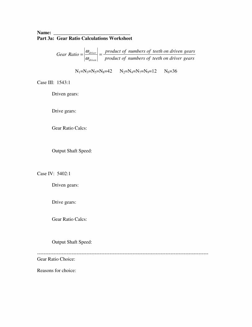
Name: _______________________________
Part 3a: Gear Ratio Calculations Worksheet
gearsdriveronteethofnumbersofproduct
gearsdrivenonteethofnumbersofproductRatioGear
driven
driver==
ω
ω
N1=N3=N5=N8=42 N2=N4=N7=N9=12 N6=36
Case I: 126:1
Driven gears:
Drive gears:
Gear Ratio Calcs:
Output Shaft Speed:
Case II: 441:1
Driven gears:
Drive gears:
Gear Ratio Calcs:
Output Shaft Speed:
Name: _______________________________
Part 3a: Gear Ratio Calculations Worksheet
gearsdriveronteethofnumbersofproduct
gearsdrivenonteethofnumbersofproductRatioGear
driven
driver==
ω
ω
N1=N3=N5=N8=42 N2=N4=N7=N9=12 N6=36
Case III: 1543:1
Driven gears:
Drive gears:
Gear Ratio Calcs:
Output Shaft Speed:
Case IV: 5402:1
Driven gears:
Drive gears:
Gear Ratio Calcs:
Output Shaft Speed:
--------------------------------------------------------------------------------------------------------
Gear Ratio Choice:
Reasons for choice: