Mechanical Design Control System Design - RPI - The Center for
30
Mechanical Design Control System Design Rafael Quintanilla Escalante March 22, 2005
Transcript of Mechanical Design Control System Design - RPI - The Center for

Mechanical DesignControl System Design
Rafael Quintanilla Escalante
March 22, 2005

Lecture Contents
• Design Process *
• Miscellaneous Components **•Gears and Belts •Flexible Couplings
•Bearings •Fixing Components to Shafts
• Stress and Strain Analysis
• Design Studies• TIM (Infrared Mexican Telescope)
* Based on the notes of Douglas Wright on Mechanical Analysis of Machine Elements, Department of Mechanical and Materials Engineering, University of Western Australia.** Based on last year’s lecture on Mechanical Design given by Ben Potsaid to the CSD class, ECSE, RPI.
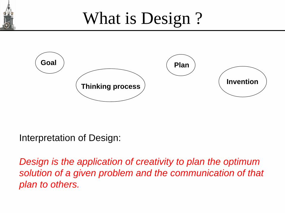
What is Design ?
Goal Plan
InventionThinking process
Interpretation of Design:
Design is the application of creativity to plan the optimum solution of a given problem and the communication of that plan to others.

The Rudimentary Design ProcessSTATE THE PROBLEM
broad, complete
GENERATE IDEASmethods
AVAILABLEKNOWLEDGE
BANK OF SOLUTION CANDIDATESuncritical – quantity not quality
RENDERPRACTICABLE
SPECIFY CONTRAINTS& CRITERIA
EVALUATECANDIDATES
OPTIMUM SOLUTION
communicate

Problem Statement• Understand the problem – communicate
Designer’s responsibility to initiate communication and clear up any misunderstanding.
• Avoid artificial constraintsReal boundary
Solution Space
Fictitious restrictions
Your limitation knowledge
Example: Team 4 - … track a target in various lighting conditions.
• Broaden the problemExample:
moreHow to reduce car’s fuel consumption? How to reduce car’s running costs?
broadlyFinancialProblems !!
Improvedriving habits
Tuneengine
Switch offengine atred lights
Ignoremaintenance
Fuelconsumption

Problem Statement (Cont.)
moremoreHow to travel between home and work at minimum cost? How to get money?broadlybroadly
walk bike bus Go to work Lotterycar Get anotherjob
• Complete the problemIdentify everyone and everything likely to be affected by any solution.
Examples: • Inaccurate launching system causes iterative refinement not been able to compensate errors.
• Team 1 spills water on the car of Team3
You must ask the right questions
BEFORE NEXT STAGE OF DESIGN, PROBLEM STATEMENTMUST BE AS BROAD AND COMPLETE AS POSSIBLE

Generation of IdeasAvoid ALL criticism while creating
Inventiveness depends upon:
• Inherited qualities: Leonardo DaVinci• Attitude: Be positive. • Knowledge: Understanding of similar problems and area of study.• Effort: Edison, inventor of the light bulb, said:
“Invention is 1% inspiration and 99% perspiration”
Ideation is carried out before considering constraints and criteria (crazy candidates trigger or are transformed into practical solutions)
QU
IT T
IME?
Rate of idea generation
Cumulative numberof ideas generated
Generate as many ideas as possible; quality doesn’t matter at this stage. However, recognize when stop inventing.
time

Specify Constraints and CriteriaIdentify ALL the constraints and criteria
• Constraints: Bounds that every candidate solution must satisfy to be valid.Examples:
• Pour water from a bottle into a cup without spilling.• The motor current should be lower than 300mA.
• Criteria: Measurements used to judge different candidate solutions.
The degree by which candidate i satisfies the criterion j may be expressed by the utility,uij, often a real number between 0 and 100%.
Examples: • Pour water from a bottle into a cup minimizing spilling.• The motor circuit should be cooled down.
Solution space can be increased by converting constraints into equivalent criteria
A common criterion which is often neglected is the need for simplicity

Render Practical
Solve secondaryproblems, modify
Candidate CANsatisfies ALL constraints ?
Candidate CANNOTsatisfies ALL constraints ?
candidate solution from bank
NO
NO
YES YES
practical solution to evaluation activity
impractical solutionto trash
A problem is trivial if it has been previously solved satisfactorily.
PROBLEM
TRIVIALSOLUTION
NEW SOLUTION
SECONDARYPROBLEM
…TERTIARYPROBLEM
TRIVIALSOLUTION
NEW SOLUTION
NEW SOLUTION
TRIVIALSOLUTION
DONE ! DONE ! DONE !

Render Practical (Cont.)
Need to consider the manufacture and operation of the candidate solution in detail.
Manufacture:• Knowledge or • Direct experimentation.
Operation:• Direct experimentation if possible (certain components or subsystems), or• Mathematical model
Inter-dependence of kinematics and forces occurs in all devices. Bewarethe dangers of a kinematic analysis without looking also at the forces involve.
Candidates must be rendered practical before evaluation

EvaluationCompare practical solution candidates based on the problem criteria
1) Relative importance of criteria
Weight wj : relative importance of the jth criterion
Example: wmass is 25% for the vacuum cleaner and 75%for the military aircraft
2) Satisfaction of the criteria - utility
Utility uij : degree to which the ith candidate satisfies the jth criterion. ( 0 ≤ uij ≤ 1 or 100%)
3) Overall utility
Ui : degree to which the ith candidate satisfies the whole problem.
∑=
=n
jijji uwU
1n = number of criteria;
Optimum candidate is the one with highest overall utility

Fixing Components to Shafts
Setscrews:
• Low torque transmission• High stress generation• Low cost
UNRELIABLE
Examples:

Fixing Components to Shafts
Pins:
• Low torque transmission• High stress generation• Low cost
Examples:
Circular or roll pinStraight round pin Tapered round pin

Fixing Components to Shafts
Keys:
• Medium torque transmission• High stress generation• Medium cost
Examples:
squarekey
flatkey
roundkey

Fixing Components to Shafts
Spline:
• High torque transmission• Low stress generation• High cost
Examples:
spline

Fixing Components to Shafts
Camp :
• High torque transmission• Low stress generation• Medium cost
Examples:

Fixing Components to Shafts

Mechanical Design
Fixing Components to Shafts
Method Torque Stress Cost
Setscrew Low High Low
Clamp High Low Med
Pin Low High Low
Key Med High Med
Spline High Low High
unreliable

Gears and Belts
Instantaneously, gears and pulleys act like levers
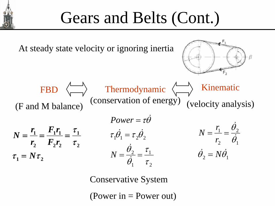
Gears and Belts (Cont.)
At steady state velocity or ignoring inertia
2
1
1
2
2211
ττ
θθ
θτθτ
θτ
==
=
=
N
Powerr F r
Nr F rN
ττ
τ τ
= = =
=
1 1 1 1
2 2 2 2
1 2
Thermodynamic(conservation of energy)
FBD
(F and M balance)
Kinematic
(velocity analysis)
12
1
2
2
1
θθ
θθ
N
rrN
=
==
Conservative System
(Power in = Power out)

Gearheads - Spur
Inexpensive
Efficient
Low torque
Some backlash
Motor and Gearhead often combined

Gearheads - Planetary
Large reduction in a small and lightweight assembly
Large torque capacity
Considerable backlash
Identical stages can be stacked together

Gearheads - Harmonic
Flexspline has 2 fewer teeth than circular spline
One tooth advances every rotation
Huge reduction in small and lightweight assembly
Almost no backlash
Aerospace and robotics applications

Gearheads Comparison
Type Torque Efficiency
Backlash
Cost
Spur Low High Low Low
Planetary
High Low High Med
Harmonic
Med Med Low High

Bearings
Inner race
Outer raceBearings are usually press fit to the shaft or housing.
Correct bearing hole diameter is critical.
Heat expansion can be used to assist assembly.
Bearings allow for slight misalignment

Flexible Couplings
Angular misalignment
Parallel offset misalignment
• Coupling is used to transmit torque between two shafts.
• Coupling is rigid in torsion and flexible in bending.
• Without flexible coupling, there would be excessive loadson the shafts and bearings.
• Without flexible coupling, bearings would fail prematurelyand performance would suffer.

Stress and StrainDynamic forces are exerted on the mechanical components.
θτ JxmF ==
Dynamic forces cause deflections (strain) and internal forces (stresses) in the structural components.
A
oLL∆
=εStrain ( ε ) :
AF
=σStress ( σ ) :

Stress and Strain
Yield Stress
(elongation)
In the linear region, material acts like a spring ( F = kx ).
Stresses in the components should never exceed the Yield Stress to prevent permanent deformation.
Why we do not design to the yield strength?

Design Study - TIM

Conclusions
• Mechanical Design and Control System Design cannot be done separately when high performance is required.
• Apply the Rudimentary Design Process.
• Don’t forget about first principles and the basics.