Mechanical characterisation of TiN/ZrN multi-layered … · This paper reports the mechanical...
7
Mechanical characterisation of TiN/ZrN multi-layered coatings C.J. Tavares a,* , L. Rebouta a , M. Andritschky a , S. Ramos b a Depto. Fı ´sica, Universidade do Minho, Azure ´m, 4800 Guimara ˜es, Portugal b Depto. Eng a Meca ˆnica (polo 2), FCT da Univ. de Coimbra, Pinhal de Marrocos, 3030 Coimbra, Portugal Abstract Ultra-microhardness, adhesion and residual-stress analysis tests were performed on reactive sputtered deposited TiN/ZrN multi-layers. Hardness values as high as 3600 Vickers were achieved for this material. Scratch tests of coatings deposited on steel substrates confirmed the existence of different mechanisms associated with total adhesion failure, depending essentially on multi-layer deposition control parameters. Stress-relaxation measurements indicated the compressive nature of these thin films. The inherent mechanical characterisation was broadened regarding the induced contributions from film thickness, total interfacial roughness, number of bi-layers and corresponding modulation periodicity. Complementary analyses with data extracted from structural XRD studies have been undertaken. # 1999 Elsevier Science S.A. All rights reserved. Keywords: Multi-layers; Ultra-microhardness; Adhesion; Residual stress; Roughness; XRD 1. Introduction Multi-layers are one-dimensional synthetic structures comprising a number of alternate layers. They fit in a vast range of optical, electrical/magnetical and protection against wear applications. Therefore, the physical properties of multi-layers have been the subject of considerable interest due to the fact that the diverse phenomena associated with very thin films, interfaces, roughness and anomalous mechanical properties, can be studied. It has been reported that multi-layer coatings may be superior to single-layer coatings regarding particular applications [1–3]. Neverthe- less, a systematic study concerning their failure mechanisms has yet to be established. Hard wear physical vapour deposited (PVD) coatings have now reached a new generation. The alternative multi-layer design is credited to the introduction of more interfaces, which permit cracks to be deflected, thereby dissipating energy and enhancing toughness. Recently it was reported that multi-layers are suited for tribological applications owing to their elevated hardness and strength [4]. Others have commented that multi-layers have superior hardness, due either to differences in dislocation line ener- gies or coherency strain fields developed between adjacent layers [5]. Moreover, the modulation period of the multi- layer is known to induce an effect on the overall micro- hardness of such coatings, this being possibly a synergistic improvement [6]. This paper reports the mechanical characterisation of TiN/ZrN multi-layer thin films grown by PVD. Ultra-micro- hardness, adhesion and residual-stress analyses have been undertaken. The deposition of these coatings was achieved by unbalanced reactive magnetron sputtering, combining RF and DC modes. 2. Fabrication of the samples The TiN/ZrN coatings were deposited using an Alcatel SCM650 sputtering system. An Ar/N 2 enriched atmosphere was present in the chamber. Two types of multi-layers were fabricated: in the static mode, alternating layers of TiN and ZrN were grown by stopping the substrate holder during a preset time interval alternately above the Ti and Zr targets; in the rotation mode the substrate holder rotates continuously (for a specific cycle period) between both targets. The Ar flow rate was kept at 100 cm 3 /min whilst the N flow rate was fixed at 2.25 cm 3 /min in the static mode and 4.25 cm 3 /min in the rotation mode. Pure Ti and Zr targets were used. The Ti target was run in the RF mode (600 W in static and 1200 W in rotation) whilst that corresponding to Zr was in the DC Journal of Materials Processing Technology 92–93 (1999) 177–183 *Corresponding author. Tel.: +351-53-510154; fax: +351-53-510153 E-mail address: [email protected] (C.J. Tavares) 0924-0136/99/$ – see front matter # 1999 Elsevier Science S.A. All rights reserved. PII:S0924-0136(99)00126-0
Transcript of Mechanical characterisation of TiN/ZrN multi-layered … · This paper reports the mechanical...
Mechanical characterisation of TiN/ZrN multi-layered coatings
C.J. Tavaresa,*, L. Reboutaa, M. Andritschkya, S. Ramosb
aDepto. FõÂsica, Universidade do Minho, AzureÂm, 4800 GuimaraÄes, PortugalbDepto. Enga MecaÃnica (polo 2), FCT da Univ. de Coimbra, Pinhal de Marrocos, 3030 Coimbra, Portugal
Abstract
Ultra-microhardness, adhesion and residual-stress analysis tests were performed on reactive sputtered deposited TiN/ZrN multi-layers.
Hardness values as high as �3600 Vickers were achieved for this material. Scratch tests of coatings deposited on steel substrates con®rmed
the existence of different mechanisms associated with total adhesion failure, depending essentially on multi-layer deposition control
parameters. Stress-relaxation measurements indicated the compressive nature of these thin ®lms. The inherent mechanical characterisation
was broadened regarding the induced contributions from ®lm thickness, total interfacial roughness, number of bi-layers and corresponding
modulation periodicity. Complementary analyses with data extracted from structural XRD studies have been undertaken. # 1999 Elsevier
Science S.A. All rights reserved.
Keywords: Multi-layers; Ultra-microhardness; Adhesion; Residual stress; Roughness; XRD
1. Introduction
Multi-layers are one-dimensional synthetic structures
comprising a number of alternate layers. They ®t in a vast
range of optical, electrical/magnetical and protection against
wear applications. Therefore, the physical properties of
multi-layers have been the subject of considerable interest
due to the fact that the diverse phenomena associated with
very thin ®lms, interfaces, roughness and anomalous
mechanical properties, can be studied. It has been reported
that multi-layer coatings may be superior to single-layer
coatings regarding particular applications [1±3]. Neverthe-
less, a systematic study concerning their failure mechanisms
has yet to be established.
Hard wear physical vapour deposited (PVD) coatings
have now reached a new generation. The alternative
multi-layer design is credited to the introduction of more
interfaces, which permit cracks to be de¯ected, thereby
dissipating energy and enhancing toughness. Recently it
was reported that multi-layers are suited for tribological
applications owing to their elevated hardness and strength
[4]. Others have commented that multi-layers have superior
hardness, due either to differences in dislocation line ener-
gies or coherency strain ®elds developed between adjacent
layers [5]. Moreover, the modulation period of the multi-
layer is known to induce an effect on the overall micro-
hardness of such coatings, this being possibly a synergistic
improvement [6].
This paper reports the mechanical characterisation of
TiN/ZrN multi-layer thin ®lms grown by PVD. Ultra-micro-
hardness, adhesion and residual-stress analyses have been
undertaken. The deposition of these coatings was achieved
by unbalanced reactive magnetron sputtering, combining RF
and DC modes.
2. Fabrication of the samples
The TiN/ZrN coatings were deposited using an Alcatel
SCM650 sputtering system. An Ar/N2 enriched atmosphere
was present in the chamber. Two types of multi-layers were
fabricated: in the static mode, alternating layers of TiN and
ZrN were grown by stopping the substrate holder during a
preset time interval alternately above the Ti and Zr targets; in
the rotation mode the substrate holder rotates continuously
(for a speci®c cycle period) between both targets. The Ar
¯ow rate was kept at 100 cm3/min whilst the N ¯ow rate was
®xed at 2.25 cm3/min in the static mode and 4.25 cm3/min in
the rotation mode. Pure Ti and Zr targets were used. The Ti
target was run in the RF mode (600 W in static and 1200 W
in rotation) whilst that corresponding to Zr was in the DC
Journal of Materials Processing Technology 92±93 (1999) 177±183
*Corresponding author. Tel.: +351-53-510154; fax: +351-53-510153
E-mail address: [email protected] (C.J. Tavares)
0924-0136/99/$ ± see front matter # 1999 Elsevier Science S.A. All rights reserved.
PII: S 0 9 2 4 - 0 1 3 6 ( 9 9 ) 0 0 1 2 6 - 0

mode (0.9 A in static and 1.0 A in rotation). The substrate
bias voltage was held at ÿ50 V. The target-to-substrate
distance was kept at 60 mm in all depositions.
The samples were grown on 40 mm diameter high-speed
steel (AISI M2) discs. These substrates were previously
heat-treated and annealed to enhance their overall
dynamic hardness. Also, prior to loading in the sputtering
chamber, the substrates were ®ne polished and cleaned
through a sequence consisting in sandpaper-to-diamond
paste abrasion, ultrasonically-enhanced alkali decreasing
and washing stages, followed by de-ionised water rinsing,
and ®nally, hot air drying. Before deposition, the substrates
were in situ sputter etched in Ar, with the RF mode (200 W),
for 15 min.
The examination of the cross-section of these coatings
with a scanning electron microscope (SEM) provided their
thickness.
3. Mechanical characterisation
In this section will be described the most important
formalism which resulted in the measurement of the
ultra-microhardness, Young's modulus, critical loads and
residual stress.
3.1. Ultra-microhardness measurements
Hardness testing has achieved the status of one of the
simplest and quickest experimental techniques by means of
which to obtain information regarding aspects of mechanical
properties. Recent developments in hardness testing have
enabled continuous monitoring of the load and depth of
penetration experienced by the indenter during the indenta-
tion process. These depth-sensing measurements allow the
estimation not only of the hardness but also of Young's
modulus.
The ultra-microhardness experiments were carried out on
a computerised Fischerscope dynamic ultra-microhardness
tester (model H100). This set-up enables continuous mon-
itoring of the load (P) and penetration depth (h) during the
indentation cycle. The tester was equipped with a quad-
rangular pyramidal Vickers indenter, possessing an apical
angle of 1368. The approach is to estimate the residual
plastic indentation depth (hp) remaining after indentation
unloading [7]. This value of hp undergoes an error correction
due to geometric defects at the indenter's tip (off-set),
yielding consequently hpc. Therefore, the equation that
enables the calculation of the Vickers hardness (HV) in
kg/mm2 is given by
HV � P
240:25 h2pc
: (1)
The denominator stands for the characteristic area func-
tion of the Vickers indenter [8]. In order to evaluate Young's
modulus, one has to determine the initial unloading contact
stiffness (S):
S � dP
dh: (2)
This is actually the slope of the initial portion of the
unloading curve. Finally, the following is obtained [8]:
Sÿ1 � dh
dP� 1
2hpc
����������
24:5
r1
Er; (3)
where Er represents the biaxial reduced modulus
1
Er
� 1ÿ v2
E� 1ÿ v2
i
Ei
: (4)
In Eq. (4), E and v stand for Young's modulus and
Poisson's ratio (v�0.3) for the ®lm, respectively. Ei and
vi denote the same quantities for the diamond indenter
(Ei�1050 GPa, vi�0.07). This leads to the ®nal equation,
which calculates the values of Young's modulus for the
coating
E � 1ÿ v2� � ���������������=24:5
p2hpc�dh=dp� ÿ ��1ÿ v2
i �=Ei����������������=24:5
p : (5)
3.2. Scratch tests
An established method of assessing the adhesion of hard
coatings made by PVD is the scratch test. During this
process, a hemispherical tipped diamond indenter is driven
over the coated surface to produce a scratch. The equipment
used was a Sebastian-5A model from the Quad Group. A
200 mm radius diamond tip was used for the stylus; the test
indentation speed was set at 0.01 cm/s, and the load rate was
kept at 1.2 N/s. The load on the diamond stylus is increased
linearly whilst at the same time the scratch length is being
monitored.
A selective and useful criteria based on acoustic emission
(AE) is employed. This AE signal is de®ned as the elastic
wave generated by the release of energy stored within the
material structure [9]. An AE transducer with a resonance
frequency of 200 kHz, which can detect acoustic bulk waves
in a frequency range of approximately 50±400 kHz (insen-
sitive to mechanical vibrations arisen from instruments: 0±
30 kHz), was used. Due to the fact that the AE signal
contains information as to the extent of the damage (released
binding energy), its signal intensity is integrated with respect
to time and subsequently transformed to an energy spectrum.
The analysis of this AE spectrum aids the identi®cation of
the value of the critical load.
The load at which the ®rst adhesion failure occurs is
known as the ®rst critical load (Lc1) [9]. Frequently this ®rst
critical load is associated with a cohesive failure related to
chipping of material from within the coating. This damage is
representative of a very weak AE signal and practically goes
unnoticed in the frictional transversal force versus scratch
length plot. Nevertheless, an experienced observer using an
optical microscope can detect this failure easily.
178 C.J. Tavares et al. / Journal of Materials Processing Technology 92±93 (1999) 177±183

The critical load characteristic of total failure of the
coating (Lc2) is regarded as the in¯ection point of the
increasing frictional force curve. This point corresponds
to the ®rst contact of the diamond with the substrate,
resulting in a change of the shear stress component [9].
The mechanisms that give rise to adhesion failures are
regarded as cohesive or adhesive damage. When chipping
occurs at some particular distance preceding the indenter it
can result in buckling and cracking in a roughly semi-
circular arc pointing towards the scratch direction [10].
The sliding stylus produces a compressive stress ®eld ahead,
which deforms the coating, bends it and pulls it underneath,
embedding the chipped material in the scratch track. When
buckling is the origin of total failure, the corresponding
critical load (Lc2) is low. Contrarily, if the mechanism that
gives rise to total failure is related to spallation, then the
critical load is higher. Spallation is an adhesive damage, and
occurs when there is ¯aking of coating material from its
interface with the substrate, being deposited subsequently on
the lateral top edge of the ®lm. This effect generates a
considerable AE signal, making its detection normally very
easy.
Two other types of failure mechanisms can be linked to
adhesion damage. Both happen when the coating remains
fully adherent to the substrate [10]. The ®rst type is named
conformal cracking, and consists of semi-circular cracks
within the scratch only, parallel to the leading edge of the
indenter. They are formed as the indenter deforms the
coating and underlying substrate, resulting in tensile bend-
ing moments within the coating as it is pushed down under-
neath the indenter. The second type bears resemblance to the
former in the way that there is also a semi-circular arc in the
scratch track, although these traces are now parallel to the
trailing edge of the stylus. The latter result from tensile
frictional stresses presents on the trailing edge of the inden-
ter; these stresses balancing the compressive stresses ahead
of the indenter.
Associated with these failure mechanisms, quite often
lateral cracking can be observed also. At low critical loads,
this lateral cracking reaches out from the semi-circular arcs
resulting from chipping and buckling. At higher critical
loads, when the tensile compressive ®eld that follows the
trailing edge of the indenter is considerable in respect to the
compressive ®elds ahead of the stylus, lateral-cracking
converging to the opposite direction of the leading stylus
takes place.
3.3. Residual stress analysis
The technique used for residual-stress measurement is
based on the associated curvature de¯ection of a thin sub-
strate [11,12]. The major advantages of this approach in
comparison to the measurements of the elastic strains in the
®lms via XRD [13] resides in the fact that in the de¯ection
method no information regarding the elastic properties of the
coating is required to calculate the residual stress.
It is well known that both the mechanical and tribological
properties of coated specimens are affected by the size and
relative spatial distribution of residual stresses [14]. An
example of this is that a high compressive stress within
the coating has been found to increase its fracture toughness
[15]. High coating toughness is a control quality sought after
in PVD coatings applied to tool steels, where wear is often
induced by propagation of cracks within the coating. How-
ever, excessive compressive stresses have the disadvantage
of provoking adhesion damage to the coatings, mainly
around the edges.
Experimentally, this technique works well when the
thickness of the substrate exceeds the ®lm thickness by at
least a factor of 100, and the lateral dimensions of the
coating and substrate are much greater than their total
thickness. In PVD coatings there is usually a large intrinsic
(microstructural) component in the residual stress (�res),
which originates: partly by the way that the crystal structure
de®nes the growth of the deposit, through changes in the
distribution, orientation and size of the crystallites
nucleated; and partly by the PVD processes itself [16].
Using the Stoney [17] equation
� � ÿ Es
6�1ÿ vs� �t2s
tc� rÿ1
a ÿ rÿ1b
� �; (6)
in which Es/(1ÿvs) refers to the biaxial modulus of the
substrate, where Es�2150 GPa and vs�0.283 [20]; tsand tc are, respectively, the thickness of the steel sub-
strate and coating; and the parameters rb and ra represent
the radius of the curvature of the substrate before and after
deposition.
The samples used were deposits of TiN/ZrN multi-layers
on 25 mm diameter and 500 mm thick stainless steel discs.
Using a Keyence 2100 laser displacement meter coupled
with a semiconductor laser, it was possible to measure the
de¯ection of the substrates prior to and after deposition. The
theory developed by Ramsey et al. [18] was used to obtain a
value for the radius of curvature of the discs. A parabolic
equation
��x� � a� bx� cx2 (7)
was ®tted to the experimental de¯ection curves, before and
after deposition. �(x) is the de¯ection as a function of the
lateral sample length; whilst a, b and c are constants. From
the latter equation, the radius of curvature is easily assessed
as
r � �ÿ2C�ÿ1: (8)
4. Experimental results
4.1. Hardness and Young's modulus
Table 1 shows the experimental results obtained for the
ultra-microhardness of the TiN/ZrN coatings. Pmax is the
C.J. Tavares et al. / Journal of Materials Processing Technology 92±93 (1999) 177±183 179

maximum load employed during the indentation cycle;
HV and E are the Vickers ultra-microhardness and
Young's modulus, respectively. Pmax was chosen taking
into account the coating thickness, in order to eliminate
possible substrate in¯uence on the ®nal results. An average
number of 6 tests was performed on each sample. Samples
M16, M18 and M21 were produced in the rotation mode
whilst the remaining samples were in the static mode. In this
table tc represents the coating thickness.
In Fig. 1 are presented the results of an indentation test
performed on a sample (M21), in order to gather data related
to its ultra-microhardness.
Fig. 2 illustrates the evolution of both the ultra-micro-
hardness values and Young's modulus, relative to the multi-
layer modulation periodicity, for TiN/ZrN multi-layer sam-
ples grown via: (a) rotation; and (b) static; modes. Error bars
are given for the sake of clarity. The bilayer period was
determined from structural re®nement of the XRD high
angle patterns of the same ®lms [19].
4.2. Adhesion tests
Table 2 presents a summary of all of the experimental
data extracted for a series of samples regarding the critical
loads detected for the ®rst failure (Lc1) and the total adhesion
failure (Lc2).
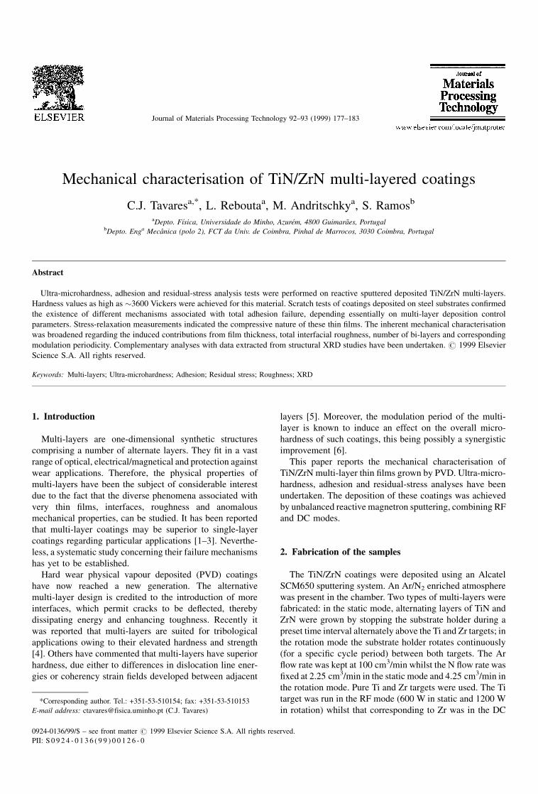
Fig. 3 represents an example of a scratch test performed
on the sample M10, grown by static mode. Visible are the
plots of the AE signal, the transversal frictional force and
Table 1
Ultra-microhardness and Young's modulus values obtained for TiN/ZrN
multi-layers
Sample tc (mm) Pmax (mN) E (GPa) HV (kg/mm2)
M14 0.95 30 228�31 1330�347
M16 1.50 50 283�6 1998�110
M17 1.14 30 273�7 2132�170
M18 1.10 30 322�28 2779�347
M20 1.86 100 318�32 3583�978
M21 1.91 50 370�31 3631�381
M22 1.81 70 244�58 1889�534
M31 1.89 70 329�13 3060�170
Fig. 1. Ultra-microhardness test performed on a sample (M21) grown in
the rotation mode. The maximum load was set at 50 mN. The creep time,
at the final stage of loading, was held for 32 s.
Fig. 2. Evolution of HV and E relative to the modulation period of the
TiN/ZrN films grown by: (a) rotation; and (b) static modes. The periodicity
was calculated by XRD refinement [19].
Table 2
Critical load values obtained for the first failure (Lc1) and total failure (Lc2)
corresponding to TiN/ZrN multi-layers, when subjected to a scratch test
Sample � (AÊ ) Lc1 (N) Lc2 (N)
M10 1000 15�5 45�2
M12 395 13�2 31�2
M13 124 10�1 20�2
M15 82 10�1 20�1
M16 115 19�6 31�3
M17 250 11�5 23�5
M18 57 16�2 29�8
M20 124 16�5 26�6
M21 74 9�2 32�2
M22 77 10�2 20�4
M31 172 24�4 34�5
M40 124 12�2 35�6
The modulation period (�) is also shown [19]. An average number of 6
tests was performed on each sample.
180 C.J. Tavares et al. / Journal of Materials Processing Technology 92±93 (1999) 177±183
load versus scratch length. Lc1 and Lc2 are clearly marked,
and were assessed by combined optical and plot analysis.
The ®rst critical load, when observing the damage optically,
was associated with chipping. The second critical load was
linked to an extensive spalling that occurred and lead to total
adhesion failure. Whilst observing Fig. 3, it is easy to point
out where this last load occurred. First, if the frictional force
plot versus scratch length is examined, there is a slight
perturbed in¯ection point indicative of this failure. Besides
this, experimentally it is found that Lc2 is directly related to
the abrupt decay of the acoustic emission signal. Never-
theless, the optical observation and position detection of the
damage due to Lc2 is essential. A rule of thumb, while
observing the damage optically, dictates the position of Lc2
to where there is approximately less than 50% of the coating
remaining. Only then and based on the observations of the
frictional force plots and AE signal, can the second critical
load be derived.
For the scratch test illustrated in Fig. 3, despite the second
critical load being identi®ed at a position �0.34 cm on the
scratch length, the coating is only removed completely at
around �0.4 cm. This is clearly seen on the frictional force
plot, where an in¯ection point occurs. On the scratch tracks,
occasionally, appear some stains that are due to substrate
roughness. These roughness peaks protrude through the
coating.
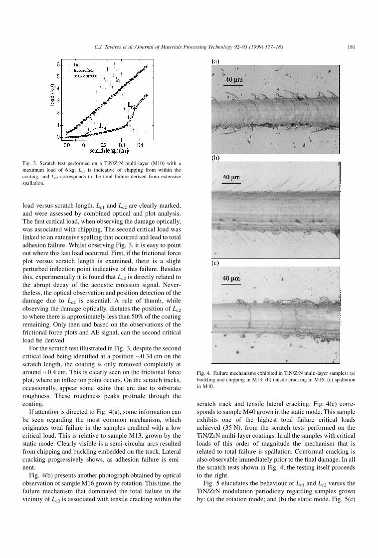
If attention is directed to Fig. 4(a), some information can
be seen regarding the most common mechanism, which
originates total failure in the samples credited with a low
critical load. This is relative to sample M13, grown by the
static mode. Clearly visible is a semi-circular arcs resulted
from chipping and buckling embedded on the track. Lateral
cracking progressively shows, as adhesion failure is emi-
nent.
Fig. 4(b) presents another photograph obtained by optical
observation of sample M16 grown by rotation. This time, the
failure mechanism that dominated the total failure in the
vicinity of Lc2 is associated with tensile cracking within the
scratch track and tensile lateral cracking. Fig. 4(c) corre-
sponds to sample M40 grown in the static mode. This sample
exhibits one of the highest total failure critical loads
achieved (35 N), from the scratch tests performed on the
TiN/ZrN multi-layer coatings. In all the samples with critical
loads of this order of magnitude the mechanism that is
related to total failure is spallation. Conformal cracking is
also observable immediately prior to the ®nal damage. In all
the scratch tests shown in Fig. 4, the testing itself proceeds
to the right.
Fig. 5 elucidates the behaviour of Lc1 and Lc2 versus the
TiN/ZrN modulation periodicity regarding samples grown
by: (a) the rotation mode; and (b) the static mode. Fig. 5(c)
Fig. 3. Scratch test performed on a TiN/ZrN multi-layer (M10) with a
maximum load of 6 kg. Lc1 is indicative of chipping from within the
coating, and Lc2 corresponds to the total failure derived from extensive
spallation.
Fig. 4. Failure mechanisms exhibited in TiN/ZrN multi-layer samples: (a)
buckling and chipping in M13; (b) tensile cracking in M16; (c) spallation
in M40.
C.J. Tavares et al. / Journal of Materials Processing Technology 92±93 (1999) 177±183 181

refers to the evolution of both critical loads, this time with
respect to the total interfacial roughness. This roughness was
calculated by structural computational re®nement of the
XRD spectra, relative to these samples [19].
4.3. Residual stress analysis
In Table 3 the experimental data obtained for the residual
stress analysis of TiN/ZrN multi-layer coatings can be seen.
In this table tc represents the coating thickness; � stands for
the multi-layer period, which was calculated by structural
re®nement of the XRD patterns [19]; rb and ra represent the
curvature radius of the samples, before and after deposition,
respectively; and �res is the residual stress. All values of �res
are indicative of compressive residual stresses within the
coatings.
Samples M21, M23 and M32 were deposited via the
rotation mode. Samples M26 and M34 refer not to multi-
layers but to thin ®lms of TiN and ZrN, respectively.
Curiously, both exhibit compressive residual stresses of
the order of �3.5 GPa. The remaining samples were grown
under the static mode.
Fig. 6 demonstrates the columnar growth characteristic of
these coatings. The sample shown corresponds to M30,
which was grown in the rotation deposition mode.
Fig. 5. Evolution of Lc1 and Lc2 critical loads in respect to the modulation period for TiN/ZrN multi-layer samples grown via: (a) the rotation mode; and (b)
the static mode. Their behaviour according to the (c) interfacial roughness [19] present on the coatings is also shown.
Table 3
Experimental compressive residual stress values obtained for a series of
studied TiN/ZrN multi-layer samples
Sample tc (mm) � (AÊ ) 1/ra-1/rb (mÿ1) �res (GPa)
M20 1.86 124 0.987 6.64
M21 1.91 74 0.232 1.52
M22 1.81 124 0.330 2.28
M23 2.17 90 0.636 3.67
M24 0.71 124 0.434 7.70
M26 1.84 ± 4.790 3.26
M31 1.89 172 1.180 7.81
M32 1.75 140 1.060 7.58
M34 4.02 ± 0.120 3.73Fig. 6. SEM photograph of sample (M30-rotation), exhibiting dense
columnar morphology. This growth is typical of TiN/ZrN multi-layers.
182 C.J. Tavares et al. / Journal of Materials Processing Technology 92±93 (1999) 177±183

Fig. 7 illustrates the behaviour of the residual stress
versus the TiN/ZrN multi-layer modulation period. This
periodicity was determined by structural simulation of the
experimental XRD patterns of the samples [19].
5. Conclusions
Reported in this paper is the production of TiN/ZrN PVD
multi-layers. Whilst studying the ultra-microhardness and
Young's modulus data obtained for the TiN/ZrN multi-layer
coatings, it is possible to comment that there is a similar
behaviour between both; regarding essentially their evolu-
tion versus number of bi-layers, modulation period, total
interfacial roughness and ®lm thickness. A slight increase on
both HVand E with modulation period is observed, although
some attention has to be reserved towards the overall ®lm
thickness. The samples created under rotation exhibited
larger values of interfacial roughness, which in¯uenced
positively HV and E; rewarding these samples with better
ultra-microhardness and Young's modulus levels in compar-
ison with similar multi-layers grown in the static mode.
Ultra-microhardness values as high as �3600 Vickers were
obtained, which is optimistic for industrial applications,
more precisely in wear prevention. The elastic Young's
modulus values are appreciable, in a range between 230
and 370 GPa; being a little lower than those published for
thin ®lms of TiN (�450 GPa [11]).
There is a link between HV, E and Lc2 values. For a large
portion of samples, higher values of ultra-microhardness and
Young's modulus corresponded to higher levels of total
failure critical loads.
The adhesion tests indicated the mechanisms that induced
failures. Through all of the experiments ful®lled, it can be
concluded that for lower critical loads (�20 N) the mechan-
ism involved is of a cohesive nature: chipping plus buckling.
At intermediate levels of Lc2 (�30 N) tensile cracking is
present, whilst at higher magnitudes of this critical load
(�32±45 N) the failure that dominates the total adhesion
damage of the coating is directly linked to spallation. Lateral
cracking is also evident, being compressive at lower levels of
Lc2 whilst at higher values it has a tensile nature.
Samples deposited under the rotation mode exhibited
similar critical loads and shared the same failure mechan-
isms, which enabled a more consistent study to be made than
grown under static conditions.
Concerning the residual stress measurements, there is a
visible increment with the decrease of the number of bi-
layers, and consequent monolayer thickness. This means
that �res increases with the thickness of a bi-layer (period),
when comparing samples with approximately the same
overall ®lm thickness. At some critical stage in the fabrica-
tion of a bi-layer, the residual stress reaches an elevated level
that causes inevitable brittleness and consequently lower
adhesion critical loads. All of the samples were character-
istic of a compressive nature having residual stresses of
between 1 and 8 GPa. The majority of these stress results for
TiN/ZrN PVD multi-layers are much higher than those
found in the literature for PVD thin ®lms of TiN
(�4.0 GPa [11]).
Acknowledgements
The authors gratefully acknowledge the ®nancial support
of the Junta Nacional de Investigac,aÄo Cientõ®ca (JNICT),
during the course of this scienti®c research, under the project
referenced as PBICT/P/CTM/1962/95.
References
[1] R. Fella et al., Surf. Coat. Tech. 36 (1988) 257.
[2] R. Schlatmann et al., Phys. Rev. B. 51 (1991) 5345.
[3] K.J. Ma et al., Surf. Coat. Tech. 76±77 (1995) 297.
[4] W.-D. Munz et al., Surf. Coat. Tech. 58 (1993) 205.
[5] M. Shinn et al., J. Mater. Res. 7 (1992) 901.
[6] X. Chu et al., Surf. Coat. Tech. 61 (1993) 251.
[7] G.M. Pharr, W.C. Oliver, MRS Bull. (1992) 28.
[8] W.C. Oliver, G.M. Pharr et al., J. Mater. Res. 7(6) (1992) 1564.
[9] V. Bellido-Gonzallez et al., Surf. Coat. Tech. 74 (1995) 884.
[10] P.J. Burnett et al., Thin Sol. Films 154 (1987) 403.
[11] M. Larsson et al., Surf. Eng. 12(1) (1996) 43.
[12] H.Y. Kumagai, Ninth International Conference on CVD, The
Electrochem. Soc., 1984, p. 189.
[13] A.J. Perry, J. Vac. Sci. Tech. A 8(3) (1990) 1351.
[14] W.D. Nix, Metall. Trans. 20A (1989) 2225.
[15] G. Kleer et al., Surf. Coat. Technol. 54±55 (1992) 165.
[16] J.-AÊ . Schweitz, J. Micromech. Microeng. 1 (1991) 10.
[17] G.G. Stoney, Proc. R. Soc. London, Ser. A 82 (1909) 172.
[18] P.M. Ramsey et al., Surf. Coat. Tech. 43±44 (1990) 223.
[19] C.J. Tavares et al., Surf. Coat. Tech. 100±101 (1998) 65.
[20] C.J. Smithels, Metals Reference Book, 5th ed., Butterworth, London,
1976, p. 975.
Fig. 7. Behaviour of the residual stress in respect to the bi-layer period, for
a series of samples. All stresses are compressive.
C.J. Tavares et al. / Journal of Materials Processing Technology 92±93 (1999) 177±183 183