Mechanical Analysis Bearings and Screws
35
Ahmed Kovacevic, City University London 1 1 Mechanical Analysis Bearings and Screws Prof Ahmed Kovacevic Lecture 2 School of Engineering and Mathematical Sciences Room CG25, Phone: 8780, E-Mail: [email protected] www.staff.city.ac.uk/~ra600/intro.htm Mechanical Analysis and Design ME 2104
-
Upload
truongdieu -
Category
Documents
-
view
223 -
download
3
Transcript of Mechanical Analysis Bearings and Screws

Ahmed Kovacevic, City University London 1 1
Mechanical Analysis Bearings and Screws
Prof Ahmed Kovacevic
Lecture 2
School of Engineering and Mathematical Sciences
Room CG25, Phone: 8780, E-Mail: [email protected]
www.staff.city.ac.uk/~ra600/intro.htm
Mechanical Analysis and Design ME 2104

Ahmed Kovacevic, City University London 2
Plan for the analysis of mechanical elements
Objective:
Procedures for design and selection of
mechanical elements
Week 1 – Shafts and keyways
Week 2 – Bearings and screws
Week 3 – Belt and chain drives
Week 4 – Gears and gear trains
Week 5 – Design Project Review
Ahmed Kovacevic, City University London 3
Plan for this week
Examples:
Bearings
Screws (with examples)
Ahmed Kovacevic, City University London 4
Rolling
element
bearings
Ahmed Kovacevic, City University London 5
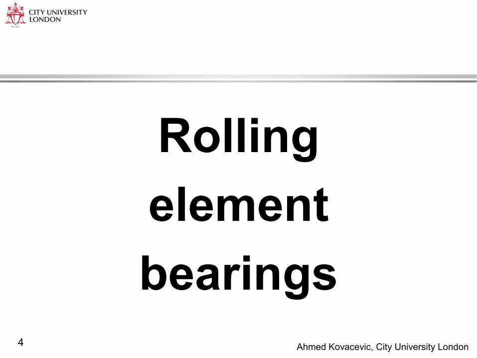
Rolling element bearings
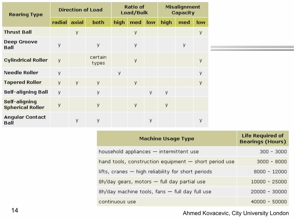
Designed to take: - Pure radial loads - Pure thrust loads - Combination of the two
kinds of loads
Main parts: - Outer ring - Inner ring - Rolling elements (balls) - Separator
Selection of bearings: - Type and amount of load
(axial - thrust, radial) - Size, Speed - Lubrication - Life rating
Ahmed Kovacevic, City University London 6
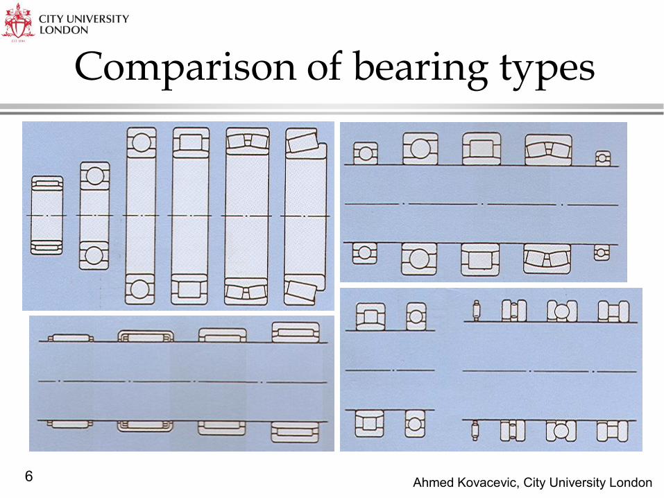
Comparison of bearing types
Ahmed Kovacevic, City University London 7
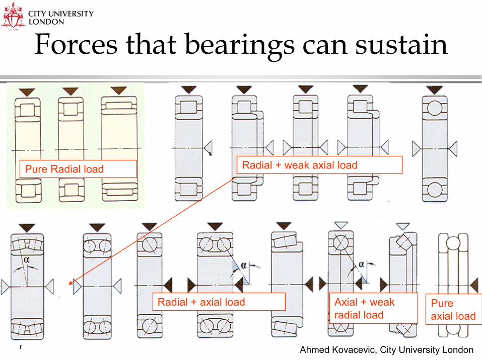
Forces that bearings can sustain
Pure Radial load
Radial + axial load Pure
axial load
Axial + weak
radial load
Radial + weak axial load
Ahmed Kovacevic, City University London 8
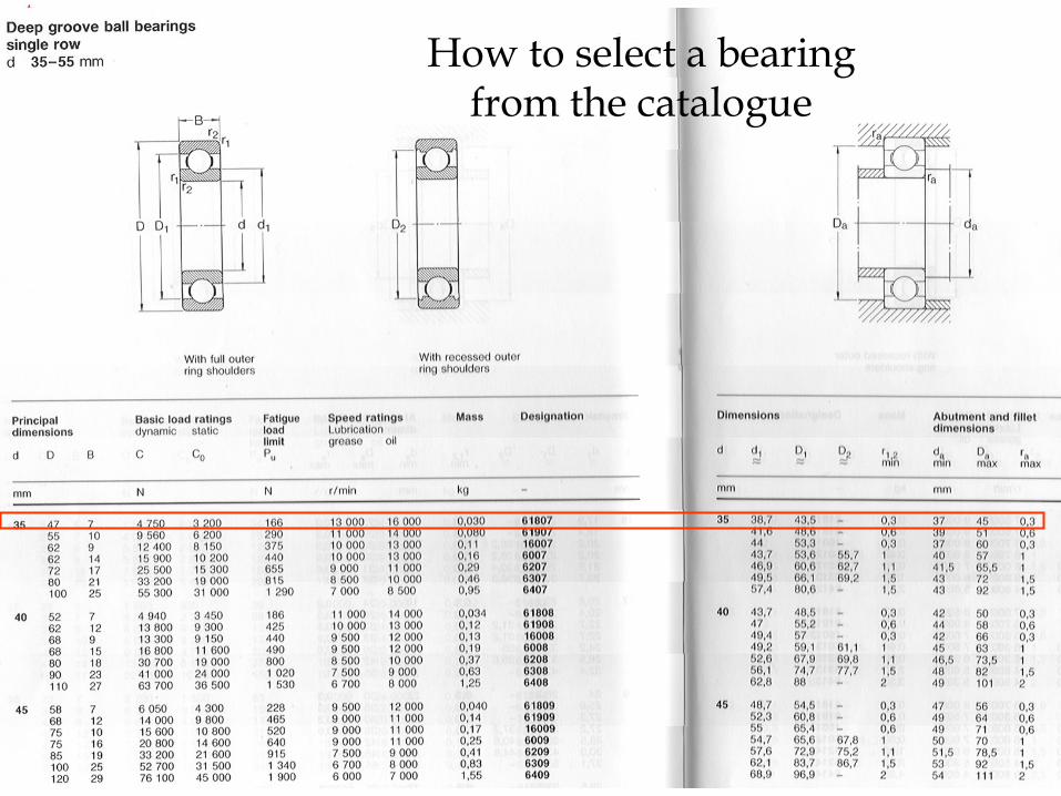
How to select a bearing from the catalogue
Ahmed Kovacevic, City University London 9
Bearing Life - Definitions
Stresses: inner ring - rolling element + rolling element - outer ring.
Metal fatigue is the only cause of failure for clean, properly lubricated,
sealed and cooled bearings. (Dynamic loading)
Endurance of a bearing is limiting factor – bearing life L:
» Number of revolutions of the inner ring until the first evidence of fatigue.
» Number of hours of use at standard angular speed until the first evidence of
fatigue
Rating life (minimum life) of a bearing, L10
» number of revolution or hours of operation that 90% of a group of identical
bearings will achieve or exceed before the failure criterion develops.
Both previous life estimations are based on the reliability factor.
The ‘new’ theory includes fatigue load limit Pu when estimating the bearing
life

Ahmed Kovacevic, City University London 10
The size of a bearing is initially selected on the relation of its load carrying
capacity and the carried load with the life and reliability requirement.
Load carrying capacity is specified for each bearing in a catalogue with:
» C – basic dynamic load rating – for variable loads and high speeds
» Co – basic static load rating - for static loads and low speeds
The load calculated from free body diagrams or by other means.
Rating life can be calculated from the life equation. The form of the life
equation depends on the accuracy required. Basic rating life is:
a = 3 - for ball bearings
a = 3.33- for roller bearings
P [N] – equivalent dynamic
load rating
n [rpm] – rotational speed
D [m] - wheel diameter
Bearing Life - Calculation
6
10
6
10 10
6
10 10
[10 ]
10[ ]
60
[10 ]1000
a
h
s
CL rev
P
L L hoursn
DL L km

Ahmed Kovacevic, City University London 11
P [N] - equivalent dynamic
bearing load
Fr [N] – actual radial bearing load
Fa [N] – actual axial bearing load
x – radial load factor
y – axial load factor
Equivalent dynamic
bearing load
r aP xF y F
Bearing type Condition x y
Deep groove ball bearing Fa/Fr<=0.5 1 0
Fa/Fr>0.5 0.56 1-2
Self aligning ball bearings Fa/Fr<=e* 1 Y*
Fa/Fr>e* 0.65 y*
Angular contact ball
bearings
Fa/Fr<=1.14 1 0
Fa/Fr>1.14 0.35 0.57
Double row angular contact
ball bearings
Fa/Fr<=0.86 1 0.73
Fa/Fr>0.86 0.62 1.17
Four-point contact ball
bearings
Fa/Fr<=0.95 1 0.66
Fa/Fr>0.95 0.6 1.07
Cylindrical roller bearing
(with flanges)
Fa/Fr<=0.2 1 0
Fa/Fr>0.2 0.92 0.6
Needle roller bearings - 1 0
Trust roller bearings - 0 1
Taper roller bearings Fa/Fr<=e* 1 0
Fa/Fr>e* 0.4 Y*
Taper roller bearings 1.00 0.75 0.60
Ahmed Kovacevic, City University London 12
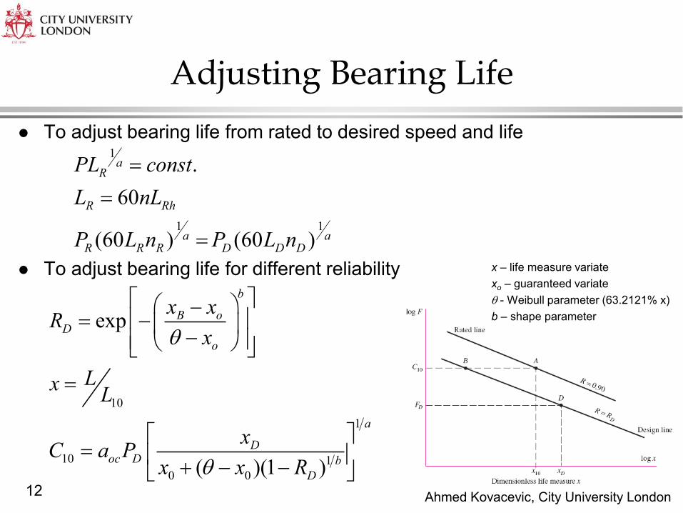
To adjust bearing life from rated to desired speed and life
To adjust bearing life for different reliability
Adjusting Bearing Life
1
1 1
.
60
(60 ) (60 )
aR
R Rh
a aR R R D D D
PL const
L nL
P L n P L n
10
1
10 1
0 0
exp
( )(1 )
b
B oD
o
a
Doc D b
D
x xR
x
LxL
xC a P
x x R
x – life measure variate
xo – guaranteed variate
- Weibull parameter (63.2121% x)
b – shape parameter

Ahmed Kovacevic, City University London 13
If the bearing is not operating in the ideal conditions then the basic rating
life should be adjusted:
aOC – application factor (quality of lubrication and sealing).
aOC = 0.20 – 2.20
Values depend on relative viscosity of lubricant.
Adjusted Bearing Life
6
10 [10 ]adj T R OCL a a a L rev
Temperature [oC] 150 200 250 300
aT 1.00 0.90 0.75 0.60
Reliability [%] 90 95 96 97 98 99
aR 1.00 0.62 0.53 0.44 0.33 0.21
Ahmed Kovacevic, City University London 14

Ahmed Kovacevic, City University London 15
Example
Ahmed Kovacevic, City University London 16
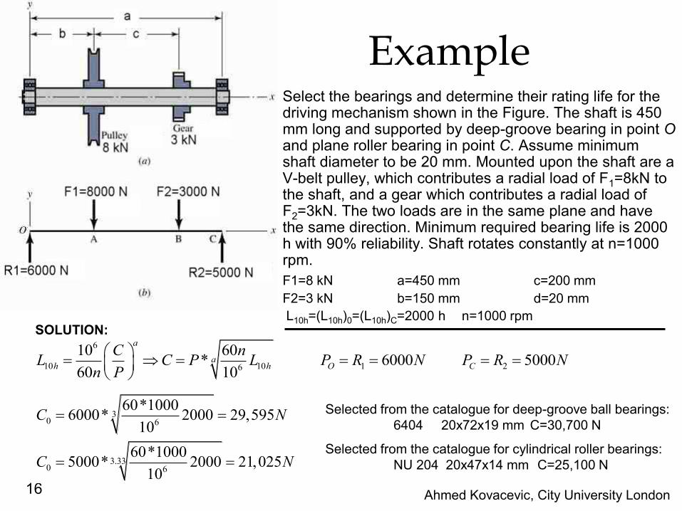
Example Select the bearings and determine their rating life for the
driving mechanism shown in the Figure. The shaft is 450 mm long and supported by deep-groove bearing in point O and plane roller bearing in point C. Assume minimum shaft diameter to be 20 mm. Mounted upon the shaft are a V-belt pulley, which contributes a radial load of F1=8kN to the shaft, and a gear which contributes a radial load of F2=3kN. The two loads are in the same plane and have the same direction. Minimum required bearing life is 2000 h with 90% reliability. Shaft rotates constantly at n=1000 rpm.
F1=8 kN a=450 mm c=200 mm
F2=3 kN b=150 mm d=20 mm
L10h=(L10h)0=(L10h)C=2000 h n=1000 rpm
SOLUTION: 6
10 10 1 26
10 60* 6000 5000
60 10
a
ah h O C
C nL C P L P R N P R N
n P
30 6
3.330 6
60*10006000* 2000 29,595
10
60*10005000* 2000 21,025
10
C N
C N
Selected from the catalogue for deep-groove ball bearings:
6404 20x72x19 mm C=30,700 N
Selected from the catalogue for cylindrical roller bearings:
NU 204 20x47x14 mm C=25,100 N
Ahmed Kovacevic, City University London 17
Screws
and
Bolts
Ahmed Kovacevic, City University London 18
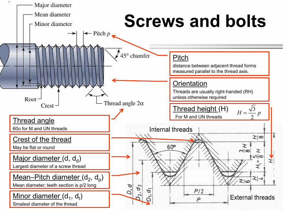
Screws and bolts
Pitch distance between adjacent thread forms
measured parallel to the thread axis.
Major diameter (d, dd) Largest diameter of a screw thread
Mean–Pitch diameter (d2, dp) Mean diameter; teeth section is p/2 long
Minor diameter (d1, dt) Smalest diameter of the thread
Orientation Threads are usually right-handed (RH)
unless otherwise required
Thread angle 60o for M and UN threads
Thread height (H) For M and UN threads
3
2H p
Crest of the thread May be flat or round

Ahmed Kovacevic, City University London 19
Screw Threads
Metric Threads:
Thread angle = 60o
Symmetric profiles
Identified as M and MJ
Coarse and fine pitch
Specification of the thread:
M12 x 1.75
The metric thread
designation
Unified threads: (usually pipe threads)
Thread angle = 60o
Symmetric profiles
Series UN and UNR
Coarse (C) and fine (F) pitch
Specification of the thread:
¼ in-20 UNRC
Nominal major
diameter
Pitch:
coarse or fine
Nominal major
diameter
Threads per inch
(coarse or fine)
Thread series:
UNC, UNF,
UNRC, UNRF
Ahmed Kovacevic, City University London 20
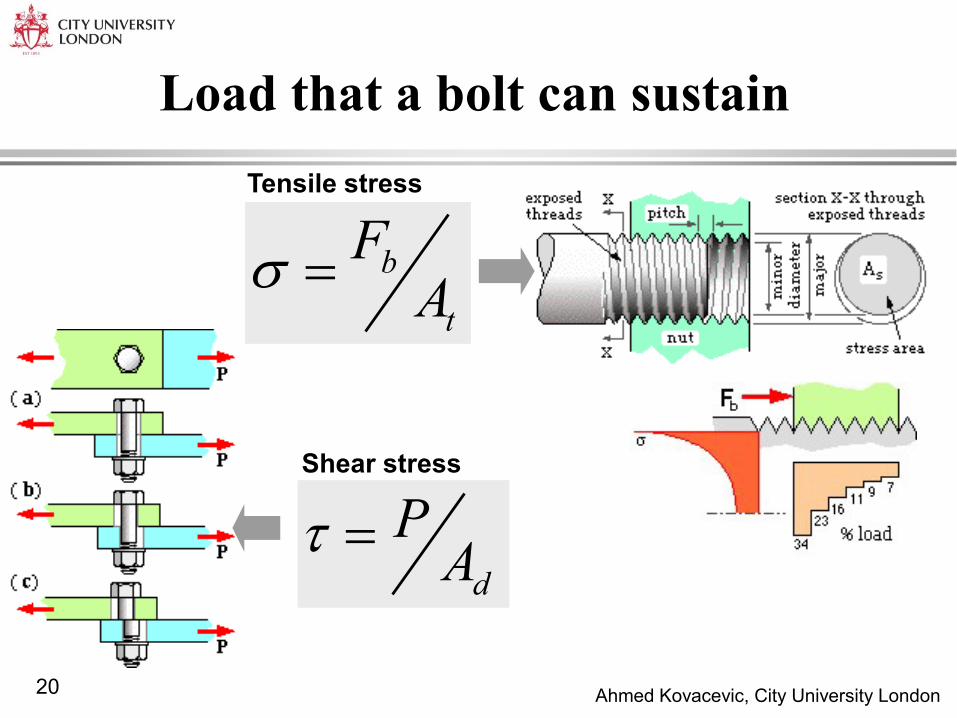
Load that a bolt can sustain
b
t
FA
d
PA
Shear stress
Tensile stress
Ahmed Kovacevic, City University London 21
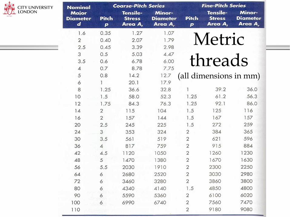
Metric threads
(all dimensions in mm)
Ahmed Kovacevic, City University London 22
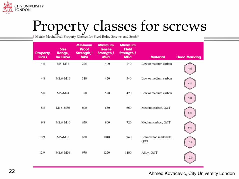
Property classes for screws

Ahmed Kovacevic, City University London 23
Joint-Fastener stiffness

Ahmed Kovacevic, City University London 24
Joint-Members stiffness
Stiffness of the joint
Load on a member
Load on the bolt
Ahmed Kovacevic, City University London 25
Statically loaded joint with Preload
Recommended Preload Proof load
Load factor per a bolt (ratio of proof load and operating load)
L total
p t i
Cn PN
S A F
Number of bolts
totalPP
N
Yielding factor of safety
Factor of safety against joint separation
Ahmed Kovacevic, City University London 26
From: Shigley’s Mechanical Engineering Design, 9th edition
Ahmed Kovacevic, City University London 27
From: Shigley’s Mechanical Engineering Design, 9th edition
Ahmed Kovacevic, City University London 28
From: Shigley’s Mechanical Engineering Design, 9th edition
Ahmed Kovacevic, City University London 29
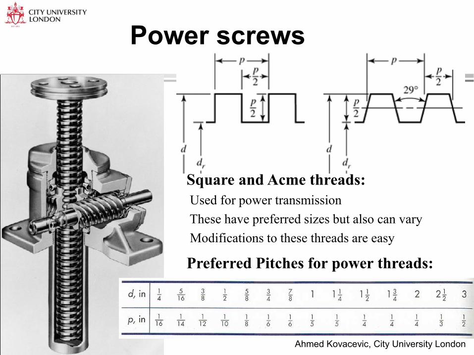
Power screws
Square and Acme threads:
Used for power transmission
These have preferred sizes but also can vary
Modifications to these threads are easy
Preferred Pitches for power threads:

Ahmed Kovacevic, City University London 30
Multiple threaded screws
(a) Single, (b) double, (c) triple threaded screws.
l=3p l=2p l=p
Ahmed Kovacevic, City University London 31
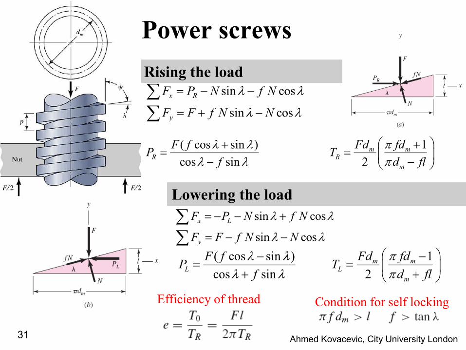
Power screws
Rising the load
sin cos
sin cos
x R
y
F P N f N
F F f N N
Lowering the load
1( cos sin )
cos sin 2
m mR R
m
Fd fdF fP T
f d fl
sin cos
sin cos
x L
y
F P N f N
F F f N N
1( cos sin )
cos sin 2
m mL L
m
Fd fdF fP T
f d fl
Condition for self locking Efficiency of thread
Ahmed Kovacevic, City University London 32
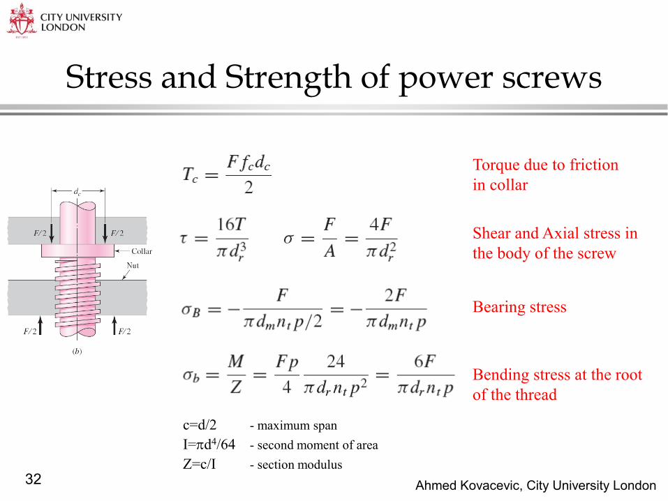
Stress and Strength of power screws
Torque due to friction
in collar
Shear and Axial stress in
the body of the screw
Bending stress at the root
of the thread
Bearing stress
c=d/2 - maximum span
I=d4/64 - second moment of area
Z=c/I - section modulus

Ahmed Kovacevic, City University London 33
Example The cover of a pressurised cylinder is attached by a
self-energising seal and 6 identical bolts M10x1.5 of
class 8.8. The fluid pressure is essentially constant at 6
MPa. A safety factor of three is required. Check if the
given bolt can sustain the pressure!
P=6MPa 6 class 8.8 M10x1.5
ds=120 mm Nd=3
-----------------------------------------------------------------------------
St /=?
SOLUTION:
Force on the cover
caused by the pressure:
2 26 0.12
6 10 67858 67.94 4
sc s c
dF p A p F N kN
Force on the individual bolt 67.9 11.36 6
cb b
FF F kN
From tables: Tensile stress area Proof strength 258tA mm 590pS MPa
Stress on each bolt: 11300 19458
b
t
FMPa
A
Selected number of bolts can sustain the load
5903.04
194
p
d
SN
Ahmed Kovacevic, City University London 34
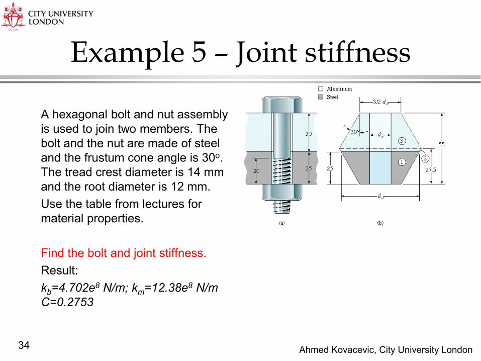
Example 5 – Joint stiffness
A hexagonal bolt and nut assembly
is used to join two members. The
bolt and the nut are made of steel
and the frustum cone angle is 30o.
The tread crest diameter is 14 mm
and the root diameter is 12 mm.
Use the table from lectures for
material properties.
Find the bolt and joint stiffness.
Result:
kb=4.702e8 N/m; km=12.38e8 N/m
C=0.2753
Ahmed Kovacevic, City University London 35
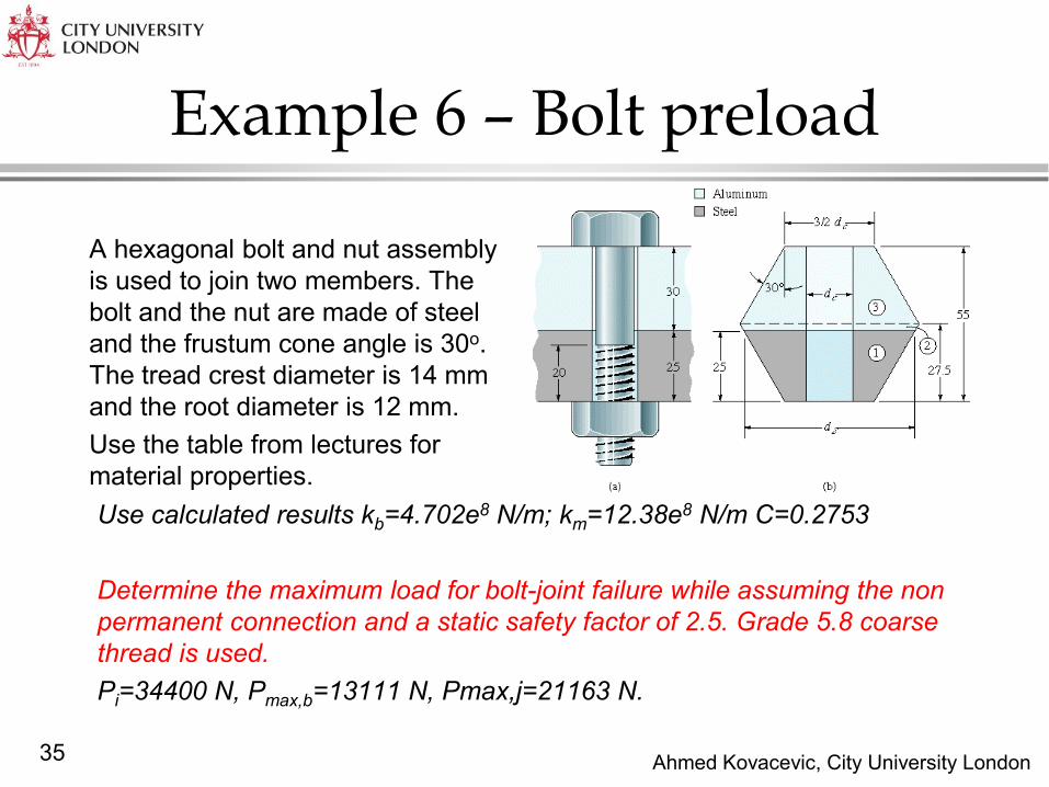
Example 6 – Bolt preload
A hexagonal bolt and nut assembly
is used to join two members. The
bolt and the nut are made of steel
and the frustum cone angle is 30o.
The tread crest diameter is 14 mm
and the root diameter is 12 mm.
Use the table from lectures for
material properties.
Use calculated results kb=4.702e8 N/m; km=12.38e8 N/m C=0.2753
Determine the maximum load for bolt-joint failure while assuming the non
permanent connection and a static safety factor of 2.5. Grade 5.8 coarse
thread is used.
Pi=34400 N, Pmax,b=13111 N, Pmax,j=21163 N.