Measuring Wheel Manual -...
20
TomTom-Tools GmbH Zelgli 20 Phone: +41 79 774 06 44 8905 Arni [email protected] Switzerland www.tomtom-tools.com 28 April 2017 Measuring Wheel 1. INTRODUCTION: The Measuring Wheel is a measurement tool, which measures the diameter of slow rotating cylinders during operation; for example on support rollers or tires on rotary kilns or dryers. These components are typically subject to a certain amount of wear and have to be re-machined or replaced after some time of operation. In order keep the kiln or drier axis aligned; it is essential to know the changes of the diameters and to compensate them by adjusting the roller positions. By measuring the diameter at various positions along the width of a support roller or tire, its cylindricity gets known, which helps to define the corrective action in case of deviations. The Measuring Wheel can be considered as a caliper to measure diameters of huge rotating cylinders. Typical applications: Diameter measurement of: • Support rollers, tires and shell on rotary kilns and rotary dryers • Trunnions or tires and shell on ball mills (measured in barring mode) 1.1 Safety: Rotary kilns, dryers and mills, where this tool typically is used, are huge rotating equipment with many pinch points, they can cause serious injuries. Therefore only specialized and trained personnel shall work close to these machines. To use the tool, follow strictly the local safety rules given by the respective plant / factory / local authorities and discuss the application with the safety engineer in charge. The tools provided by TomTom-Tools GmbH have proven their functionality in various applications; nevertheless TomTom-Tools GmbH does not take any responsibility for the application on site regarding safety. The plant is responsible for the safety, according to the local law, in a way that nobody can be hurt or injured. The application and safety instructions below are guidelines and not exhausted which include the experience from previous measurement campaigns and might need to be adapted to the local safety requirements.
Transcript of Measuring Wheel Manual -...

TomTom-Tools GmbH Zelgli 20 Phone: +41 79 774 06 44 8905 Arni [email protected] Switzerland www.tomtom-tools.com
28 April 2017
Measuring Wheel
1. INTRODUCTION: The Measuring Wheel is a measurement tool, which measures the diameter of slow rotating cylinders during operation; for example on support rollers or tires on rotary kilns or dryers. These components are typically subject to a certain amount of wear and have to be re-machined or replaced after some time of operation. In order keep the kiln or drier axis aligned; it is essential to know the changes of the diameters and to compensate them by adjusting the roller positions. By measuring the diameter at various positions along the width of a support roller or tire, its cylindricity gets known, which helps to define the corrective action in case of deviations.
The Measuring Wheel can be considered as a caliper to measure diameters of huge rotating cylinders.
Typical applications: Diameter measurement of:
• Support rollers, tires and shell on rotary kilns and rotary dryers
• Trunnions or tires and shell on ball mills (measured in barring mode)
1.1 Safety:
Rotary kilns, dryers and mills, where this tool typically is used, are huge rotating equipment with many pinch points, they can cause serious injuries. Therefore only specialized and trained personnel shall work close to these machines. To use the tool, follow strictly the local safety rules given by the respective plant / factory / local authorities and discuss the application with the safety engineer in charge.
The tools provided by TomTom-Tools GmbH have proven their functionality in various applications; nevertheless TomTom-Tools GmbH does not take any responsibility for the application on site regarding safety. The plant is responsible for the safety, according to the local law, in a way that nobody can be hurt or injured. The application and safety instructions below are guidelines and not exhausted which include the experience from previous measurement campaigns and might need to be adapted to the local safety requirements.
Page 2 April 28, 2017
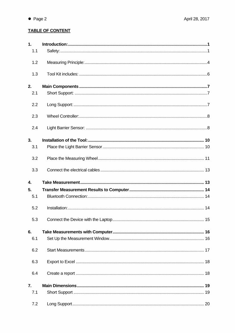
TABLE OF CONTENT
1. Introduction: ............................................................................................................................. 1 1.1 Safety: .................................................................................................................................... 1
1.2 Measuring Principle: .............................................................................................................. 4
1.3 Tool Kit includes: ................................................................................................................... 6
2. Main Components ................................................................................................................... 7 2.1 Short Support: ....................................................................................................................... 7
2.2 Long Support: ........................................................................................................................ 7
2.3 Wheel Controller: ................................................................................................................... 8
2.4 Light Barrier Sensor: ............................................................................................................. 8
3. Installation of the Tool: ........................................................................................................ 10 3.1 Place the Light Barrier Sensor ........................................................................................... 10
3.2 Place the Measuring Wheel ............................................................................................... 11
3.3 Connect the electrical cables ............................................................................................. 13
4. Take Measurement ............................................................................................................... 13 5. Transfer Measurement Results to Computer ................................................................... 14
5.1 Bluetooth Connection: ........................................................................................................ 14
5.2 Installation: .......................................................................................................................... 14
5.3 Connect the Device with the Laptop .................................................................................. 15
6. Take Measurements with Computer .................................................................................. 16 6.1 Set Up the Measurement Window ..................................................................................... 16
6.2 Start Measurements ........................................................................................................... 17
6.3 Export to Excel ................................................................................................................... 18
6.4 Create a report ................................................................................................................... 18
7. Main Dimensions .................................................................................................................. 19 7.1 Short Support ..................................................................................................................... 19
7.2 Long Support ...................................................................................................................... 20

Page 3 April 28, 2017
Caution:
Pinch Points: Do not put your hands nor any items close or into pinch points (e.g. girth gear / pinion, kiln tires / support rollers,…)
Keep safe distance to avoid getting caught by moving parts.
Never place the Measuring Wheel on the side of the pinch point between support roller and tire ; place it always on the out running side, to avoid the items get caught between
Magnet Fields:
Be aware of the strong magnet field of the magnet stands.
Keep the tool away from people with pace makers or any other sensitive item as credit cards or magnetic data carrier.
Clamping:
Do not put fingers between the magnets and magnetic surface. There is the risk for clamping or pinching, due to the strong magnetic force.
Gloves:
Wear proper gloves to protect your hands from hot and rough surfaces and sharp edges.
Hot Surface: After using the tool, some components might be very hot; especially the switch flag and the light barrier sensor
Let them cool down before stowage. Otherwise the box may get damaged.
Radio Waves:
Be aware of the radio waves (Bluetooth) which are emitted from the tool as well from the Bluetooth adapter on the computer.
Do not keep the tool unnecessary in operation; switch it off, after usage.

Page 4 April 28, 2017
Magnetic Switch Flag
Measuring Wheel with Encoder
Wheel Controller
Light Converter
Spring Loaded Wheel Suspension
Light Barrier Sensor (heat resistant 180°C)
Diameter to measure
1.2 Measuring Principle:
The Measuring Wheel kit consists of three main components, the wheel itself with the integrated rotation encoder, the heat resistant light barrier sensor to indicate the rotation of the item to be measured and the controller which calculates and displays the diameter.
The wheel with the diameter of 176mm is running without slippage on the surface to be measured (e.g. support roller). During each wheel revolution 1760 electrical impulse are sent to the Wheel Controller which is counting them.
With the help of a magnetic switch flag attached to the side face of the support roller or tire, the light barrier sensor provides each revolution an electrical impulse to the Wheel Controller. This revolution impulse starts the counting of the impulses coming from the wheel encoder. After one revolution of the support roller or tire, a new impulse from the barrier sensor is stopping the counting, the diameter value is displayed and immediately the next measuring cycle is started.
With each revolution the diameter value is refreshed whereupon the last reading appears at the lowest of the three rows in the display. The second and the third row show the previous readings.
a) Schematic with Light Barrier Sensor (standard)

Page 5 April 28, 2017
Measurement of kiln tire diameter
Measurement of support roller diameter

Page
2
5
8
1.3 To
The Meafollowing
1. M
2. W
3. L
4. L
5. S
6. M
7. M
8.
9. Ma
10. Te
11. A
12. M
e 6
ool Kit incl
asuring Wheg items:
Measuring
Wheel Con
Light Barrie
Light Conv
Sensor Cab
Magnetic SIncluding ba
Magnetic SIncluding ma
Battery Cha
Magnetic swand extensio
Transport Cextra tough,
Allen Key fo
Manual (in l
4
ludes:
eel is comin
Wheel with
troller with
er Sensor w
verter for Lig
bles with 2 a
Stand for Mease plate wit
Stand for Ligagnetic base
arger with d
witch flag won rods
Case with fo water and d
or assembly
lid)
3
g as a tool k
integrated r
graphic disp
with opening
ght Barrier S
and 5m leng
easuring Whh 8 magnets
ght Barrier Se, connector
different plug
with heat res
oam cushiondust seal (su
y
6
kit in a strong
rotation enco
play
g 80mm, hea
Sensor
gth
heel s, connector
ensor rs and exten
g adapters (1
sistant magn
ning, uitable for ai
6
g and tight t
oder and sp
at resistant u
rs and 4 exte
nsion rod
100…240VA
net (up to 30
ir cargo)
ransport cas
ring loaded
up to 180°C
ension rods
AC)
00°C)
Apri
1
10
se, which inc
wheel susp
TranspType: E67x51xWeight
l 28, 2017
7
9
0
11
cludes the
ension
port Case Explorer 582x26.2cm
total: 24kg
23

Page 7 April 28, 2017
Extension rod
Wheel Controller
Light Barrier Sensor
Light Converter
Base plate
Clamping handle
Adjustmen handle
Wheel (hardened
stainless steel)
Tilt adjustment screw
Spring suspension hub
Rotation encoder in wheel hub
Connector (M12 4pole)
Magnet (max 8 pieces)
2. MAIN COMPONENTS
2.1 Short Support:
Wheel directly mounted to the base plate
2.2 Long Support:
Wheel mounted on extended support to reach further. To give the necessary hold in case of extending with more than 2 rods, it is recommended to use 8 magnets on the base plate.

Page
Light (ma
2.3 W
The Whthe follow
•
•
•
2.4 Li
Light BaelectricaIt consis
•
•
•
•
e 8
Mag(ma
Converter ax 60°C)
Wheel Contr
eel Controllewing compo
Switch boa
Re-charge
Tough hou Note: The tof the hous(by turning
ight Barrie
arrier Sensoral impulse tosts mainly of
Light Convthe light pas(Attention: m
Light Barri(heat resist
Magnet Stawith differen
Magnetic Swith differen
net Stand ax 80°C)
Charge(9…25
Graph
Power
roller:
er supplies tonents:
ard with imp
eable batter
using with tw
two magnetsing can be rmagnets co
r Sensor:
r provides eo start and stf the followin
verter whichssing througmax. temp.
ier Fork withtant up to 18
and nt extension
Switch Flagnt extension
er Plug 5VDC)
hic Display
Switch
the power a
pulse counte
ies 4 pieces
wo plugs to
s on the bacremoved if nounter-clockw
ach revolutiotop the meang compone
h sends andgh the optica60°C)
h optical cab80°C)
n rods
g n rods
nd processe
er, graphical
s, size AA, ty
connect the
ck not required,wise)
on preciselyasurement.nts:
receives al cables
bles
es the acqui
display and
ype NiMH (1
e wheel and
y an
Maw
red values.
d battery ma
1.2V, >1900m
the light bar
Apri
Optical CLength(max 1
Ligh(m
agnetic Swithcwith extension
(max 300°C
Connect(M12
2 Ma(back
It consists m
nagement.
mAh)
rrier sensor
l 28, 2017
Cables : 1.5m 80°C)
ht Barrier Formax 180°C)
ch Flagn rods C)
tor Plugs 4pole)
gnets k side)
mainly of
rk

Page 9 April 28, 2017
Magnetic Switch Flag (difuse reflection plate)
Measuring Wheel with Encoder
Light Reflection Sensor (heat resistant 180°C)
Diameter to measure
Light Converter
Magnetic Switch Flag (difuse reflection plate)
Light Reflection Sensor (heat resistant 180°C)
Light Converter
b) Schematic with Light Reflection Sensor (optional) In case of narrow space, it is possible to replace the abovementioned light barrier sensor by this small light sensor, which works by reflection in the range of approximately 10…30mm distance.
Note: With this sensor it is important to use the switch flag with sharp edges in order to get repetitive accurate impulses; do not use the hexagonal studs nor the round magnet body as switch flag.

Page 10 April 28, 2017
Swithch Flag
Light Barrier Sensor on kiln tire
3. INSTALLATION OF THE TOOL:
3.1 Place the Light Barrier Sensor
Place the Magnet Stand of the Light Barrier Sensor onto a magnetic surface near the side face of the support roller or tire, which has to be measured. Try to minimize the exposure to heat.
Attach the magnetic switch flag to the side face of the roller or tire. Make sure there is sufficient clearance and the surface does not have thick dust build up to prevent the magnet from falling. Special attention has to be given on kiln tires that the switch flag is not interfering with the thrust roller. Adjust the Light Barrier Fork in a way that the switch flag is passing through the fork and interrupts the light beam. The light beam is not visible but the two lenses where the light is passing can be found on the two ends of the fork. The signal is indicated later by a light in the Light Converter and with a symbol in the display of the Wheel Controller.
Light Barrier Sensor on support roller
Swithch Flag
Caution Hot! Wear Gloves! The tire and afterwards the Switch Flag might be very hot

Page
3.2 Pl
Place thAssure extensioaddition
For safecontact w
Dependdifferent
For the the midd
To get provides
CautioStro
e 11
lace the Me
he Magnet Ssufficient c
on rods, theal magnets
ety, hold thewith only tw
ing on the t positions a
purpose of dle is taken.
information s a clear bas
on Clampingong Magnets
M
easuring W
Stand of theleanliness o range can to the basep
e base platewo magnets a
purpose to long the wid
kiln axis alig
about the se for decisio
g!
Measure the d
Wheel
e wheel ontoof the contabe increase
plate, they c
e not directlas shown in
measure tdth.
gnment or g
cylindricity ons about p
Base Pla(8 Magne
diameter on d
o a magnetact surfacesed to more can be found
ly but on th the followin
the roller or
general wea
various mepossible requ
ate ets)
Placin
ifferent positio
tic surface ns to have sthan 2m. In
d in the case
e Extensionng picture.
r tire diamet
r measurem
easurementuired re-mac
ng the magne
ons
near the supsufficient stan this case ite under the w
n Rod. To a
ter the whe
ment, typical
ts along thechining of the
etic Base Plat
Apri
pport roller oability. By at is requiredwheel.
avoid shock
eel can be
ly only one
e width aree roller or tir
te
l 28, 2017
or the tire. adding the d to attach
s, get first
placed on
reading in
e taken. It re surface.

Page 12 April 28, 2017
Rotation
Adjustment of the contact pressure Adjustment of the straightness
The following sketch provides recommendations for placing the Measuring Wheel.
Place the wheel only in safe areas. Keep distance to the pinch point between support roller and tire.
Never place the Measuring Wheel or the Light Barrier Sensor on the side of the pinch point; place it always on the out running side, to avoid the items get caught between.
Please note also the orientation of the wheel suspension in relation to the sense of rotation.
To avoid slippage it is important that the wheel is adjusted in line with the running surface and some pressure is applied. The pressure can be adjusted by loosening the clamping handle on the hub of the lever arm and pushing the wheel against the surface. Tighten the lever arm again, after adjustment. To fine tune the straightness use the tilt screw as shown in the picture below.
Caution! Pinch Points
Keep safe distance

Page
3.3 C
ConnectControlledevices
4. TAStart thethe icon Also thethrough.high tem
The diamlowest rothe high
WTem
e 13
onnect the
t the Measuer. It does nand allocate
AKE MEASe Wheel Con appears in
e icon for the. To protect
mperature, a
meter valuesow and pus
hest diamete
Wheel mperature
e electrical
uring Wheenot matter, wes the signa
SUREMENTntroller. As sthe display
e Light Barriethe wheel, it
an alarm mes
s are shownhes the prev
er value has
Wheel Icon
cables
el and the Lwhich plug
als according
T soon the whenext to the re Sensor apts temperatussage will ap
n in stack movious valuesto be found
Measu
9…25VDC
555
Light Barrieris used for
gly.
eel is turningrespective pppears and inure is measuppear and th
ode with thres up. This m; the value w
I - 0
uring W
5 6 2 4 . 35 6 2 5 . 55 6 2 5 . 5
r Sensor wwhich sens
g it is recognlug. ndicates whured and dishe wheel ha
ee rows. Theakes the finewith no whee
tomtom
Wheel
3 5 5
ith the two sor; the cont
nized by the
en the switcsplayed on thas to be remo
e latest value tuning of thel slippage.
m-tools.com
Light Barrier
Apri
cables to ttroller is det
e wheel cont
ch flag passehe screen. Ioved from th
ue is displayehe wheel ea
Icon
BatterStatu
LDiam
l 28, 2017
the Wheel tecting the
roller and
es n case of he kiln.
ed in the asy, where
ry s
Latest meter Value
[mm]

Page 14 April 28, 2017
5. TRANSFER MEASUREMENT RESULTS TO COMPUTER There exists the possibility to transfer the measured values, which are displayed on the Wheel Controller, directly via Bluetooth to a computer (Windows). It makes it very easy to save, visualize and analyze the results.
5.1 Bluetooth Connection:
Typically the distance between the Wheel Controller and the Laptop is short; hence the inbuilt Bluetooth interface is strong enough and can be used to connect.
In case a stronger connection is required, use the USB Bluetooth adapter UD100.
Windows recognizes the hardware and automatically installs the suitable driver
5.2 Installation:
The software (TomTom-Tools Measurement Studio), which is used for the Measuring Wheel, comes along with the equipment on a USB memory stick. Nevertheless it is recommended to install the software from www.tomtom-tools.com , where always the latest version is available.
During any start of the Measurement Studio, it is checking for updates if the computer is connected to the internet. In case of available upgrades the user gets asked if they should be downloaded and installed.
Click to download the software
Click to install the software
Page 15 April 28, 2017
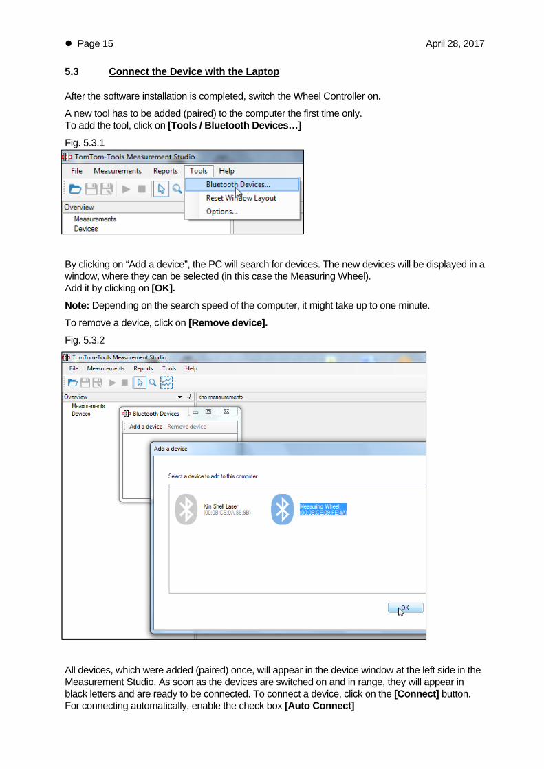
5.3 Connect the Device with the Laptop
After the software installation is completed, switch the Wheel Controller on.
A new tool has to be added (paired) to the computer the first time only. To add the tool, click on [Tools / Bluetooth Devices…] Fig. 5.3.1
By clicking on “Add a device”, the PC will search for devices. The new devices will be displayed in a window, where they can be selected (in this case the Measuring Wheel). Add it by clicking on [OK]. Note: Depending on the search speed of the computer, it might take up to one minute.
To remove a device, click on [Remove device]. Fig. 5.3.2
All devices, which were added (paired) once, will appear in the device window at the left side in the Measurement Studio. As soon as the devices are switched on and in range, they will appear in black letters and are ready to be connected. To connect a device, click on the [Connect] button. For connecting automatically, enable the check box [Auto Connect]

Page 16 April 28, 2017
Fig. 5.3.3 (Device Window)
6. TAKE MEASUREMENTS WITH COMPUTER 6.1 Set Up the Measurement Window
• To set up a new measurement, click on: [Measurement / New / Measuring Wheel / Kiln Diameter]
Fig. 6.1.1
• The first pier will be displayed as per default • More piers can be added by the right mouse click “Add pier ” as shown in Fig. 6.1.2 • Put some additional useful information about the measurement into the “Settings Window” • Specify if the “Material Flow direction” by right mouse click
Device can be connected, when displayed in black
letters here
To connect click here

Page 17 April 28, 2017
Fig. 6.1.2
6.2 Start Measurements
• To start a new measurement, click on the Start Button or press F5
The values will appear in the graph and the red line indicates the shape of the outer surface of rollers and tire.
• To stop the measurement, click on the Stop Button or press F6 With that, the last value will remain in on the screen
Enter additional Information Select the Roller
by clicking
Add more piers by right mouse click
Detail window of selected roller
Support Roller
Tire Surface
Page 18 April 28, 2017
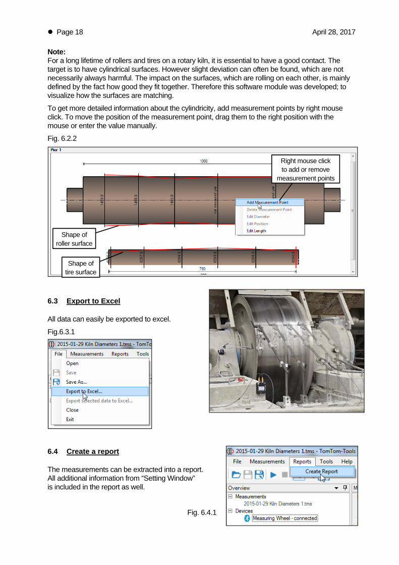
Note: For a long lifetime of rollers and tires on a rotary kiln, it is essential to have a good contact. The target is to have cylindrical surfaces. However slight deviation can often be found, which are not necessarily always harmful. The impact on the surfaces, which are rolling on each other, is mainly defined by the fact how good they fit together. Therefore this software module was developed; to visualize how the surfaces are matching.
To get more detailed information about the cylindricity, add measurement points by right mouse click. To move the position of the measurement point, drag them to the right position with the mouse or enter the value manually.
Fig. 6.2.2
6.3 Export to Excel
All data can easily be exported to excel.
Fig.6.3.1
6.4 Create a report
The measurements can be extracted into a report. All additional information from “Setting Window” is included in the report as well.
Fig. 6.4.1
Shape of roller surface
Shape of tire surface
Right mouse click to add or remove
measurement points

Page 19 April 28, 2017
7. MAIN DIMENSIONS
7.1 Short Support

Page 20 April 28, 2017
7.2 Long Support
TomTom-Tools GmbH Switzerland www.tomtom-tools.com [email protected]