Measuring speed, air, fuel of i.c. engine
14
MEASURING SPEED, FUEL & AIR OF I.C. ENGINE SHANTANU GIRDE, G.H.R.C.E., NAGPUR.
-
Upload
shantanu-girde -
Category
Engineering
-
view
617 -
download
2
Transcript of Measuring speed, air, fuel of i.c. engine

MEASURING SPEED, FUEL &
AIR OF I.C. ENGINE
SHANTANU GIRDE, G.H.R.C.E., NAGPUR.

Measurement of Engine Speed:
A wide variety of speed measuring devices are
available in the market. They range from a mechanical
tachometer to digital and triggered electrical
tachometers.
The best method of measuring speed is to count the
number of revolutions in a given time. This gives an
accurate measurement of speed. Many engines are
fitted with such revolution counters.
A mechanical tachometer or an electrical tachometer
can also be used for measuring the speed.
Engine speed:
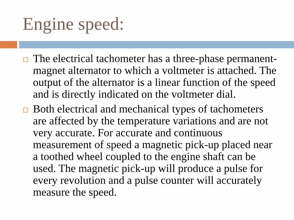
The electrical tachometer has a three-phase permanent-magnet alternator to which a voltmeter is attached. The output of the alternator is a linear function of the speed and is directly indicated on the voltmeter dial.
Both electrical and mechanical types of tachometers are affected by the temperature variations and are not very accurate. For accurate and continuous measurement of speed a magnetic pick-up placed near a toothed wheel coupled to the engine shaft can be used. The magnetic pick-up will produce a pulse for every revolution and a pulse counter will accurately measure the speed.

Engine speed:
Mechanical Tachometer Electrical
Tachometer
Engine speed:
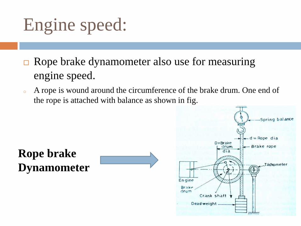
Rope brake dynamometer also use for measuring
engine speed.
o A rope is wound around the circumference of the brake drum. One end of
the rope is attached with balance as shown in fig.
Rope brake
Dynamometer

Fuel Consumption Measurement
Fuel consumption is measured in two ways :
(a)The fuel consumption of an engine is measured
by determining the volume flow in a given time interval
and multiplying it by the specific gravity of the fuel
which should be measured occasionally to get an accurate
value.
(b) Another method is to measure the time required
for consumption of a given mass of fuel.

Fuel Measurement:
As already mentioned two basic types of fuel
measurement methods are :
(1)Volumetric type:
Volumetric type flowmeter includes Burette
method, Automatic Burette flowmeter and Turbine
flowmeter.
Turbine
Flowmeter

Fuel Measurement:
(2)Gravimetric type:
The efficiency of an engine is related to the
kilograms of fuel which are consumed and not the
number of litres. The method of measuring volume flow
and then correcting it for specific gravity variations is
quite inconvenient and inherently limited in accuracy.
Instead if the weight of the fuel consumed is directly
measured a great improvement in accuracy and cost can
be obtained.
There are three types of gravimetric type
systems which are commercially available include Actual
weighing of fuel consumed, Four Orifice Flowmeter, etc.

Air Consumption Measurement:
One can say the mixture of air and fuel is the food for
an engine. For finding out the performance of the
engine accurate measurement of both is essential.
In IC engines, the satisfactory measurement of air
consumption is quite difficult because the flow is
pulsating, due to the cyclic nature of the engine and
because the air a compressible fluid. Therefore, the
simple method of using an orifice in the induction pipe
is not satisfactory since the reading will be pulsating
and unreliable.

Air Measurement:
All kinetic flow-inferring systems such as nozzles,
orifices and venturies have a square law relationship
between flow rate and differential pressure which gives
rise to severe errors on unsteady flow. Pulsation
produced errors are roughly inversely proportional to
the pressure across the orifice for a given set of flow
conditions. The various methods and meters used for
air flow measurement include
(a) Air box method, and
(b) Viscous-flow air meter.

Air supply to engine(carburetor)
Generally u tube manometer is use to check inlet air
pressure and by equation air consumption also find out.
Measurement
of Air
by Air Box
Method.

Air Measurement:
Measurement of Air Supply of an I.C. Engine:
Let a = area of orifice in m3.
Cd = Coefficient of discharge of the orifice.
ΔH= Difference of pressure as measured in cm.
of water.
Ma= Mass of one cubic metre of air, in kg.
Mw=Mass of one cubic metre of water, in kg.
H= Head causing flow through the orifice in m.
of air.

Air Measurement:
V= Velocity of air flowing through the orifice inmetre per sec.
Q= Discharge of air flowing through the orifice ,in m3 per sec.
Now, consider one m3 of air at a pressure of ‘p’N/m2 and absolute temperature ‘T’, Kelvin.
Then, applying gas=n
pv=Ma.RT
But v=1m3
∴ Ma=𝑝
𝑅𝑇

Air Measurement:
Ma=𝑝
287.𝑇( ∵ R=287 J/kg-K) ----1
Now, H =△𝐻
100X𝑀𝑤
𝑀𝑎m of air
Also, V = Cd. 2𝑔𝐻
And Q= a.V
∴ Q=a.Cd. 2𝑔𝐻 -----2
Now, using the equation 1 and 2 the mass of the air
supplied can be calculated as follows.
Mass of air supplied = Q.Ma

![METHANE – A FUEL FOR · PDF fileMETHANE – A FUEL FOR AGRICULTURE ... - compressed natural gas (CNG) ... Fig.1. A typology of alternative fuels used in I.C. engines [1]](https://static.fdocuments.in/doc/165x107/5ab238f07f8b9a7e1d8d3a51/methane-a-fuel-for-a-fuel-for-agriculture-compressed-natural-gas-cng.jpg)