Measuring Geometrical Parameters of Involute Spur … Geometrical Parameters of Involute Spur Gears...
7
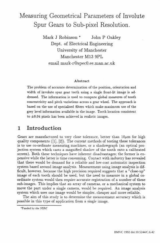
Measuring Geometrical Parameters of Involute Spur Gears to Sub-pixel Resolution. Mark J Robinson * John P Oakley Dept. of Electrical Engineering University of Manchester Manchester M13 9PL email mark-r<Q>specO.ee .man.ac.uk Abstract The problem of accurate determination of the position, orientation and width of involute spur gear teeth using a single front-lit image is ad- dressed. The information is used to compute global measures of tooth concentricity and pitch variations across a gear wheel. The approach is based on the use of specialised filters which make maximum use of the grey level information available in the image. Tooth location consistent to ±0.04 pixels has been achieved in realistic images. 1 Introduction Gears are manufactured to very close tolerance, better than 10/zm for high quality components ([l], [2]). The current methods of testing these tolerances is to use co-ordinate measuring machines, or a shadowgraph (an optical pro- jection system which casts a magnified shadow of the tooth onto a calibrated screen). Both these techniques have inherent disadvantages; the former is ex- pensive while the latter is time consuming. Contact with industry has revealed that there would be demand for a reliable and low-cost automatic inspection system based around image analysis. Measurement using image analysis is dif- ficult, however, because the high precision required suggests that a "close-up" image of each tooth should be used, but the need to measure in a global co- ordinate system would then require accurate registration of a number of these sub-images. This implies that an array of cameras, or a. mechanical system to move the part under a single camera, would be required. An image analysis system which uses one image would be simpler, cheaper and more reliable. The aim of this study is to determine the measurement accuracj' which is possible in this type of application from a single image. •Funded by the SERC BMVC 1992 doi:10.5244/C.6.42
Transcript of Measuring Geometrical Parameters of Involute Spur … Geometrical Parameters of Involute Spur Gears...
Measuring Geometrical Parameters of Involute
Spur Gears to Sub-pixel Resolution.
Mark J Robinson * John P Oakley
Dept. of Electrical Engineering
University of Manchester
Manchester M13 9PL
email mark-r<Q>specO.ee .man.ac.uk
Abstract
The problem of accurate determination of the position, orientation andwidth of involute spur gear teeth using a single front-lit image is ad-dressed. The information is used to compute global measures of toothconcentricity and pitch variations across a gear wheel. The approach isbased on the use of specialised filters which make maximum use of thegrey level information available in the image. Tooth location consistentto ±0.04 pixels has been achieved in realistic images.
1 Introduction
Gears are manufactured to very close tolerance, better than 10/zm for highquality components ([l], [2]). The current methods of testing these tolerancesis to use co-ordinate measuring machines, or a shadowgraph (an optical pro-jection system which casts a magnified shadow of the tooth onto a calibratedscreen). Both these techniques have inherent disadvantages; the former is ex-pensive while the latter is time consuming. Contact with industry has revealedthat there would be demand for a reliable and low-cost automatic inspectionsystem based around image analysis. Measurement using image analysis is dif-ficult, however, because the high precision required suggests that a "close-up"image of each tooth should be used, but the need to measure in a global co-ordinate system would then require accurate registration of a number of thesesub-images. This implies that an array of cameras, or a. mechanical system tomove the part under a single camera, would be required. An image analysissystem which uses one image would be simpler, cheaper and more reliable.
The aim of this study is to determine the measurement accuracj' which ispossible in this type of application from a single image.
•Funded by the SERC
BMVC 1992 doi:10.5244/C.6.42
410
Pitch circle
Dedenduml
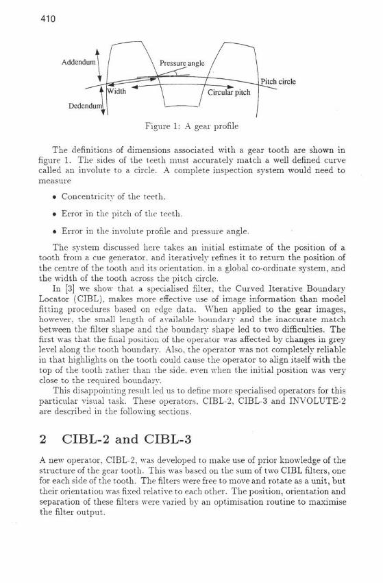
Figure 1: A gear profile
The definitions of dimensions associated with a gear tooth are shown infigure 1. The sides of the teeth must accurately match a well defined curvecalled an involute to a circle. A complete inspection sj'stem would need tomeasure
• Concentricity of the teeth.
• Error in the pitch of the teeth.
• Error in the involute profile and pressure angle.
The system discussed here takes an initial estimate of the position of atooth from a cue generator, and iteratively refines it to return the position ofthe centre of the tooth and its orientation, in a global co-ordinate s)rstem, andthe width of the tooth across the pitch circle.
In [3] we show that a specialised filter, the Curved Iterative BoundaryLocator (CIBL), makes more effective use of image information than modelfitting procedures based on edge data. When applied to the gear images,however, the small length of available boundary and the inaccurate matchbetween the filter shape and the boundary shape led to two difficulties. Thefirst was that the final position of the operator was affected by changes in greylevel along the tooth boundary. Also, the operator was not completely reliablein that highlights on the tooth could cause the operator to align itself with thetop of the tooth rather than the side, even when the initial position was veryclose to the required boundary.
This disappointing result led us to define more specialised operators for thisparticular visual task. These operators, CIBL-2. CIBL-3 and INVOLUTE-2are described in the following; sections.
2 CIBL-2 and CIBL-3A new operator, CIBL-2, was developed to make use of prior knowledge of thestructure of the gear tooth. This was based on the sum of two CIBL filters, onefor each side of the tooth. The filters were free to move and rotate as a unit, buttheir orientation was fixed relative to each other. The position, orientation andseparation of these niters were varied by an optimisation routine to maximisethe filter output.
411
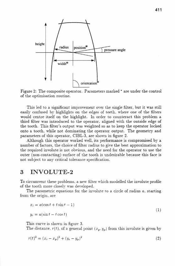
pressure angle
Figure 2: The composite operator. Parameters marked * are under the controlof the optimisation routine.
This led to a significant improvement over the single filter, but it was stilleasily confused by highlights on the edges of teeth, where one of the filterswould centre itself on the highlight. In order to counteract this problem athird filter was introduced to the operator, aligned with the outside edge ofthe tooth. This filter's output was weighted so as to keep the operator lockedonto a tooth, while not dominating the operator output. The geometry andparameters of this operator, CIBL-3, are shown in figure 2.
Although this operator worked well, its performance is compromised by anumber of factors, the choice of filter radius to give the best approximation tothe required involute is not obvious, and the need for the operator to use theouter (non-contacting) surface of the tooth is undesirable because this face isnot subject to any critical tolerance specification.
3 INVOLUTE-2To circumvent these problems, a new filter which modelled the involute profileof the tooth more closely was developed.
The parametric equations for the involute to a circle of radius a. startingfrom the origin, are
x, = «(cos t + t sin / — 1)
y, = a(s'mt — tcost)(1)
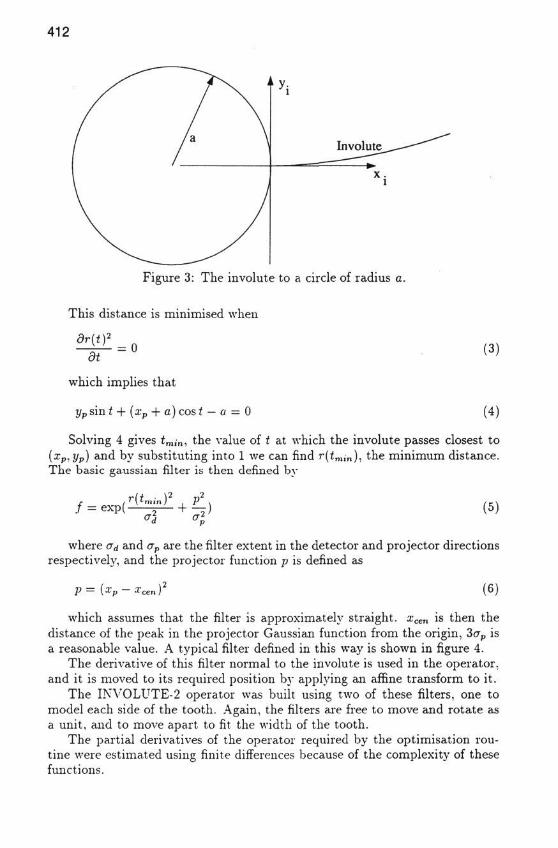
This curve is shown in figure 3.The distance. r(t), of a general point (xv.yp) from this involute is given by
r ( t ) 2 = (x, - x , , ) 2 + { y , - y p ) (2)
412
Figure 3: The involute to a circle of radius a.
This distance is minimised when
= 0&t
which implies that
yp sin t + (xp + a) cos t - a = 0
(3)
(4)
Solving 4 gives £„„•„, the value of t at which the involute passes closest to(ip, yp) and by substituting into 1 we can find r(<m;n), the minimum distance.The basic gaussian filter is then defined by
= exp( r(tmln)(5)
where (id and av are the filter extent in the detector and projector directionsrespectively, and the projector function p is defined as
p = (xp - xc (6)
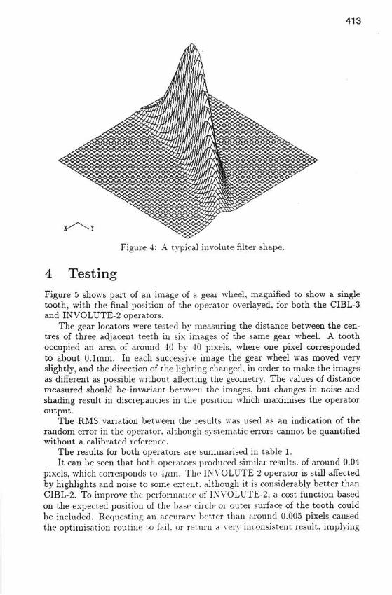
which assumes that the filter is approximately straight. xcen is then thedistance of the peak in the projector Gaussian function from the origin, 3crp isa reasonable value. A typical filter defined in this way is shown in figure 4.
The derivative of this filter normal to the involute is used in the operator,and it is moved to its required position by apph'ing an affine transform to it.
The INVOLUTE-2 operator was built using two of these filters, one tomodel each side of the tooth. Again, the filters are free to move and rotate asa unit, and to move apart to fit the width of the tooth.
The partial derivatives of the operator required by the optimisation rou-tine were estimated using finite differences because of the complexity of thesefunctions.
413
Figure 4: A typical involute filter shape.
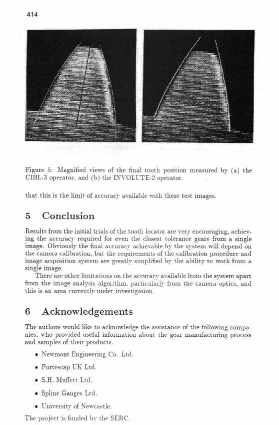
4 TestingFigure 5 shows part of an image of a gear wheel, magnified to show a singletooth, with the final position of the operator overlayed, for both the CIBL-3and INVOLUTE-2 operators.
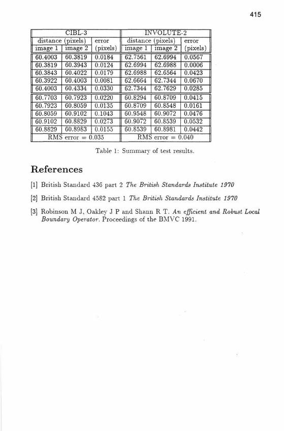
The gear locators were tested by measuring the distance between the cen-tres of three adjacent teeth in six images of the same gear wheel. A toothoccupied an area of around 40 by 40 pixels, where one pixel correspondedto about 0.1mm. In each successive image the gear wheel was moved veryslightly, and the direction of the lighting changed, in order to make the imagesas different as possible without affecting the geometry. The values of distancemeasured should be invariant between the images, but changes in noise andshading result in discrepancies in the position which maximises the operatoroutput.
The RMS variation between the results was used as an indication of therandom error in the operator, although systematic errors cannot be quantifiedwithout a calibrated reference.
The results for both operators are summarised in table 1.It can be seen that both operators produced similar results, of around 0.04
pixels, which corresponds to 4/an. The INVOLUTE-2 operator is still affectedby highlights and noise to some extent, although it is considerably better thanCIBL-2. To improve the performance of INVOLUTE-2, a cost function basedon the expected position of the base circle or outer surface of the tooth couldbe included. Requesting an accuracy better than around 0.005 pixels causedthe optimisation routine to fail, or return a very inconsistent result, implying
414
Figure 5: Magnified views of the final tooth position measured by (a) theCIBL-3 operator, and (b) the INVOLUTE-2 operator.
that this is the limit of accuracy available with these test images.
5 ConclusionResults from the initial trials of the tooth locator are very encouraging, achiev-ing the accuracj- required for even the closest tolerance gears from a singleimage. Obviously the final accuracy achievable by the system will depend onthe camera calibration, but the requirements of the calibration procedure andimage acquisition system are greatly simplified by the ability to work from asingle image.
There are other limitations on the accuracy available from the system apartfrom the image analysis algorithm, particularly from the camera optics, andthis is an area currently under investigation.
6 AcknowledgementsThe authors would like to acknowledge the assistance of the following compa-nies, who provided useful information about the gear manufacturing processand samples of their products.
• Newmont Engineering Co. Ltd.
• Portescap UK Ltd.
• S.H. Muffett Ltd.
• Spline Gauges Ltd.
• University of Newcastle.
The project is funded by the SERC.
415
CIBL-3distance (pixels)
image 160.400360.381960.384360.392260.400360.770360.792360.805960.910260.8829
image 260.381960.394360.402260.400360.433460.792360.805960.910260.882960.8983
error(pixels)0.01840.01240.01790.00810.03300.02200.01350.10430.02730.0155
RMS error = 0.035
INVOLUTE-2distance (pixels)
image 162.756162.699462.698862.666462.734460.829460.870960.954860.907260.8539
image 262.699462.698862.656462.734462.762960.870960.854860.907260.853960.8981
error(pixels)0.05670.00060.04230.06700.02850.04150.01610.04760.05320.0442
RMS error = 0.040
Table 1: Summary of test results.
References[1] British Standard 436 part 2 The British Standards Institute 1970
[2] British Standard 4582 part 1 The British Standards Institute 1970
[3] Robinson M J, Oakley J P and Shann R T. An efficient and Robust LocalBoundary Operator. Proceediiags of the BMVC 1991.