
Measuring Fingertip Forces by Imaging the Fingernail
7
Measuring Fingertip Forces by Imaging the Fingernail Yu Sun, John M. Hollerbach * School of Computing University of Utah Stephen A. Mascaro † Department of Mechanical Engineering University of Utah Abstract This paper presents an external camera method for mea- suring fingertip forces by imaging the fingernail and sur- rounding skin. This method is an alternative to the pho- toplethysmograph sensor originally developed by one of the authors. A 3D model of the fingernail surface and skin is obtained with a stereo camera and laser striping system. Subsequent images from a single camera are registered to the 3D model by adding fiducial markings to the fingernail. Calibration results with a force sensor show that the mea- surement range depends on the region of the fingernail and skin. A Bayesian method is developed to predict fingertip force given coloration changes. Preliminary accuracy results for normal and shear force measurement are presented. In comparison to the results using the photoplethysmograph fingernail sensor, our results are more accurate and double the range of forces that can be transduced, all the way up to the saturation level. CR Categories: H.5.2 [INFORMATION INTERFACES AND PRESENTATION]: User Interfaces—Haptic I/O; Keywords: fingertip force, fingernail, coloration, image registration, Bayesian 1 Introduction The use of coloration change in the fingernail to predict fin- gertip force was originally proposed by Mascaro and Asada [6]. The blood flowing under the fingernail is affected by the pressure at the fingerpad, and the coloration change in the fingernail provides a surprisingly good transduction of fingerpad force [7]. Shear forces as well as normal forces can be measured, although there is coupling between them [8]. To image the fingernail, Mascaro and Asada [6] devised a photoplethysmograph sensor comprised of an array of 6 LEDs to illuminate the fingernail and an array of 8 photodetectors to measure the coloration. These arrays are embedded in an epoxy substrate shaped like an artificial fingernail (Figure 1), which is individually fitted and attached to a subject’s fingernail. Wires are routed out for interface with a com- puter. Sensor response was linear up to 1 N normal force and beyond 1 N there was a nonlinear leveling off [8]. With a linear model, the sensor predicted normal force to within 1 N accuracy in the range of 2 N and shear force to within 0.5 N accuracy in the range of 3 N. In current grasping studies, instrumented objects are typ- ically created that incorporate miniature 6-axis force/torque sensors at predefined grasp points [12]. The subject is not free to grasp an object in different ways or to change grasp * e-mail: {ysun,jmh}@cs.utah.edu † e-mail:[email protected] (A) (B) Figure 1: (A) The underside of the photoplethysmograph fingernail sensor. (B) The sensor attached to the fingernail. Figure 2: Contact conditions that influence coloration include normal force fz , shear forces fx and fy , fingertip orientation φx (pitch) and φy (roll), and finger joint angle J 3 . points. The fingernail-based force sensing technique has the great advantage that objects do not have to be instrumented and everyday objects can be used. There is no constraint on how a subject changes grasp points. The need to fabricate sensors fitted to each fingernail is currently a disadvantage. Other limitations are the sparse sampling of the fingernail and the lack of imaging of the surrounding skin, whose coloration change we have found to transduce fingertip force well also. Besides normal and shear forces, other factors that influence fingernail coloration in- clude the contact orientation, the curvature of the contact, and the DIP joint angle (Figure 2). They all combine to affect the coloration pattern, but it is asking a lot of a fixed sparse sampling of the fingernail image to separate the influ- ences of these factors. We have also found that the fingernail coloration saturates at lower force levels than the surround- ing skin. This paper presents an alternative approach: an external camera system that provides a fuller imaging of the back of the fingertip. The use of an external camera system presents challenges of keeping the fingernail in view, the lighting en- vironment, and registration. None of these challenges is an issue with the photoplethysmograph sensor, since the sensor is fixed to the back of the nail and the lighting environment is controlled. Nevertheless, the high resolution of the fingernail image and surrounding skin is an offsetting advantage pro- 125 Symposium on Haptic Interfaces for Virtual Environment and Teleoperator Systems 2006 March 25 - 26, Alexandria, Virginia, USA 1-4244-0226-3/06/$20.00 ©2006 IEEE
Transcript of Measuring Fingertip Forces by Imaging the Fingernail

Measuring Fingertip Forces by Imaging the Fingernail
Yu Sun, John M. Hollerbach∗
School of Computing
University of Utah
Stephen A. Mascaro†
Department of MechanicalEngineering
University of Utah
Abstract
This paper presents an external camera method for mea-suring fingertip forces by imaging the fingernail and sur-rounding skin. This method is an alternative to the pho-toplethysmograph sensor originally developed by one of theauthors. A 3D model of the fingernail surface and skin isobtained with a stereo camera and laser striping system.Subsequent images from a single camera are registered tothe 3D model by adding fiducial markings to the fingernail.Calibration results with a force sensor show that the mea-surement range depends on the region of the fingernail andskin. A Bayesian method is developed to predict fingertipforce given coloration changes. Preliminary accuracy resultsfor normal and shear force measurement are presented. Incomparison to the results using the photoplethysmographfingernail sensor, our results are more accurate and doublethe range of forces that can be transduced, all the way upto the saturation level.
CR Categories: H.5.2 [INFORMATION INTERFACESAND PRESENTATION]: User Interfaces—Haptic I/O;
Keywords: fingertip force, fingernail, coloration, imageregistration, Bayesian
1 Introduction
The use of coloration change in the fingernail to predict fin-gertip force was originally proposed by Mascaro and Asada[6]. The blood flowing under the fingernail is affected bythe pressure at the fingerpad, and the coloration change inthe fingernail provides a surprisingly good transduction offingerpad force [7]. Shear forces as well as normal forces canbe measured, although there is coupling between them [8].
To image the fingernail, Mascaro and Asada [6] devised aphotoplethysmograph sensor comprised of an array of 6 LEDsto illuminate the fingernail and an array of 8 photodetectorsto measure the coloration. These arrays are embedded in anepoxy substrate shaped like an artificial fingernail (Figure1), which is individually fitted and attached to a subject’sfingernail. Wires are routed out for interface with a com-puter. Sensor response was linear up to 1 N normal forceand beyond 1 N there was a nonlinear leveling off [8]. Witha linear model, the sensor predicted normal force to within1 N accuracy in the range of 2 N and shear force to within0.5 N accuracy in the range of 3 N.
In current grasping studies, instrumented objects are typ-ically created that incorporate miniature 6-axis force/torquesensors at predefined grasp points [12]. The subject is notfree to grasp an object in different ways or to change grasp
∗e-mail: {ysun,jmh}@cs.utah.edu†e-mail:[email protected]
(A) (B)
Figure 1: (A) The underside of the photoplethysmograph fingernailsensor. (B) The sensor attached to the fingernail.
Figure 2: Contact conditions that influence coloration include normalforce fz , shear forces fx and fy , fingertip orientation φx (pitch) andφy (roll), and finger joint angle J3.
points. The fingernail-based force sensing technique has thegreat advantage that objects do not have to be instrumentedand everyday objects can be used. There is no constraint onhow a subject changes grasp points.
The need to fabricate sensors fitted to each fingernail iscurrently a disadvantage. Other limitations are the sparsesampling of the fingernail and the lack of imaging of thesurrounding skin, whose coloration change we have found totransduce fingertip force well also. Besides normal and shearforces, other factors that influence fingernail coloration in-clude the contact orientation, the curvature of the contact,and the DIP joint angle (Figure 2). They all combine toaffect the coloration pattern, but it is asking a lot of a fixedsparse sampling of the fingernail image to separate the influ-ences of these factors. We have also found that the fingernailcoloration saturates at lower force levels than the surround-ing skin.
This paper presents an alternative approach: an externalcamera system that provides a fuller imaging of the back ofthe fingertip. The use of an external camera system presentschallenges of keeping the fingernail in view, the lighting en-vironment, and registration. None of these challenges is anissue with the photoplethysmograph sensor, since the sensoris fixed to the back of the nail and the lighting environment iscontrolled. Nevertheless, the high resolution of the fingernailimage and surrounding skin is an offsetting advantage pro-
125
Symposium on Haptic Interfaces for Virtual Environment and Teleoperator Systems 2006March 25 - 26, Alexandria, Virginia, USA1-4244-0226-3/06/$20.00 ©2006 IEEE
viding that these challenges can be met. Furthermore, theexternal camera approach does not encumber a subject andthere is no need for sensor fabrication and individual fitting.The existence of low-cost cameras and of image processingmethods readily performed on PCs makes the instrumenta-tion costs of such an approach relatively low.
In this paper, we consider a fixed fingertip pressing againsta 6-axis force sensor and imaged by a camera system in acontrolled lighting environment. We do not yet consider is-sues of finger tracking or of handling variable lighting en-vironments. The reason is to explore the fundamental ef-fect of fingertip force versus fingernail coloration, withoutyet throwing in such complicating factors. We present re-sults regarding the dependence of force range on the regionof the fingernail and surrounding skin. A Bayesian estima-tion method is developed to predict fingerpad force from col-oration changes. Preliminary results of force prediction ac-curacy for normal and shear forces separately are presented.
2 Calibration Stage
Figure 3: (A) A Flea 2D high-resolution camera images a contactplane mounted on a 6-axis JR3 force sensor and manual Cartesianstage. (B) Dome light and a molded plastic arm supporter withVelcro strips to provide arm fixation.
Figure 3 shows a calibration stage comprised of a 6-axisJR3 force sensor mounted on a small manual Cartesian stage,a Flea CCD video camera (Point Grey Research, Inc), anda small light dome. A rubber-surface flat plane is mountedon the JR3 force sensor to provide a contact surface; theCartesian table is adjusted to locate the contact plane be-neath a subject’s fingertip. The subject’s arm is fixated bya molded plastic arm support and Velco strips; the plasticarm has 2 DOFs for position adjustment. A subject sits in achair adjustable with 4 DOF for positioning relative to theexperimental stage.
The small light dome provides a controled lighting envi-roment so that the images taken at different times are com-parable. A reflective hemisphere was created from moldedpastic; a hole at the top permits visual access by the Fleacamera. LEDs placed along the perimeter reflect off thedome to create uniform lighting on the fingernail surfaceand to avoid specular reflection.
Images are captured from the Flea camera at 30 fps, syn-chronously with recorded forces from the JR3 force sensor.In combination with the lens, the Flea camera measures animage that is about 8 cm along the optical axis and is about4x3 cm in crossection. The green channel from the cam-era’s RGB color space has been found to produce a largercoloration response and better linearity with force than theother color channels, and is used subsequently.
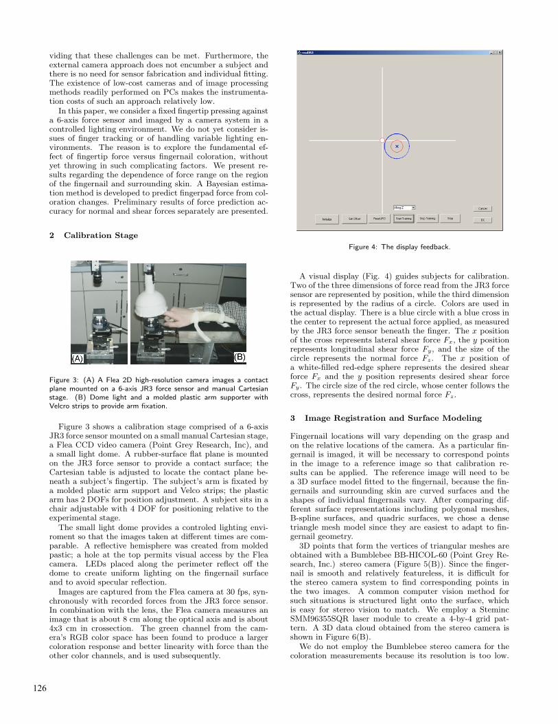
Figure 4: The display feedback.
A visual display (Fig. 4) guides subjects for calibration.Two of the three dimensions of force read from the JR3 forcesensor are represented by position, while the third dimensionis represented by the radius of a circle. Colors are used inthe actual display. There is a blue circle with a blue cross inthe center to represent the actual force applied, as measuredby the JR3 force sensor beneath the finger. The x positionof the cross represents lateral shear force Fx, the y positionrepresents longitudinal shear force Fy, and the size of thecircle represents the normal force Fz. The x position ofa white-filled red-edge sphere represents the desired shearforce Fx and the y position represents desired shear forceFy. The circle size of the red circle, whose center follows thecross, represents the desired normal force Fz.
3 Image Registration and Surface Modeling
Fingernail locations will vary depending on the grasp andon the relative locations of the camera. As a particular fin-gernail is imaged, it will be necessary to correspond pointsin the image to a reference image so that calibration re-sults can be applied. The reference image will need to bea 3D surface model fitted to the fingernail, because the fin-gernails and surrounding skin are curved surfaces and theshapes of individual fingernails vary. After comparing dif-ferent surface representations including polygonal meshes,B-spline surfaces, and quadric surfaces, we chose a densetriangle mesh model since they are easiest to adapt to fin-gernail geometry.
3D points that form the vertices of triangular meshes areobtained with a Bumblebee BB-HICOL-60 (Point Grey Re-search, Inc.) stereo camera (Figure 5(B)). Since the finger-nail is smooth and relatively featureless, it is difficult forthe stereo camera system to find corresponding points inthe two images. A common computer vision method forsuch situations is structured light onto the surface, whichis easy for stereo vision to match. We employ a StemincSMM96355SQR laser module to create a 4-by-4 grid pat-tern. A 3D data cloud obtained from the stereo camera isshown in Figure 6(B).
We do not employ the Bumblebee stereo camera for thecoloration measurements because its resolution is too low.
126

(A)
Figure 5: (A-B) The Bumblebee stereo camera. (C)The grid patternthat is projected onto the fingernail by the laser module.
However, its output is adequate for determining a 3D meshmodel. To map the high-resolution Flea 2D images to a 3Dmodel, we employ a well-known technique from computervision [2] of adding fiducial marks to the fingernail and sur-rounding skin with a black marker (Figure 6(A)). It is nec-essary that the relative locations of the fiducial markings inthe 3D model be known; this knowledge is obtained usingthe stereo camera. The fiducial marks are then automati-cally detected in the 2D image from the Flea camera [13]and used to compute the extrinsic parameter matrix [R t],where R and t are the rotation and displacement from the2D image to the coordinates of the 3D model (Figure 7).
The homogeneous coordinates of a point i in the 2D imagepi and in the 3D model Pi are
pi = [ui vi 1]T Pi = [X Y Z 1]T
where the 2D camera coordinates are (ui, vi). Let K be theintrinsic parameter matrix for the camera, and define the3x4 transformation
M = K [R t] = [m1 m2 m3]T
The transform relation between the two coordinates is pi =M Pi. Hence
mT1 Pi − (mT
3 Pi)ui = 0 (1)
mT2 Pi − (mT
3 Pi)vi = 0 (2)
With 6 fiducial marks, the parameters in M can be cal-ibrated with linear least squares. A registration result isshown in Figure 6(C).
4 Coloration Response
Figure 8 shows the coloration response hi of one typical pointi in the fingernail to a normal force fi on the finger pad. Theresponse curve shows that the coloration starts to changewhen the force reaches a certain level fa and then stopschanging at force fb because of saturation. Point i can onlytransduce the force in the measurement range [fa, fb].
To find the measurement range, the gradient curve of theresponse curve is calculated.
1. Locally weighted linear regression is used to fit theresponse curve [9]. The weighting function is wk =
(A)
(B)
(C)
Figure 6: (A) Fingernail with fiducial marks. (B) 3D point cloudfrom the stereo camera. (C) Triangular 3D mesh with color mappedfrom the 2D image.
exp(−D(fk, fi)2/K2
w), where i is the index of the querypoint, and k is the index of points around i. It giveslarger weight to the points close to the query pointand small weights to far points. This curve fitting em-phasizes local information, which can pick up turningpoints. A typical result is shown in Figure 8.
2. Local gradients on the fitted curve are calculated bydifferentials.
3. A threshold gth is set. The crossing points where thegradient curve crosses the threshold are found. Themeasurement range [fa, fb] is the segment that startsfrom a rising crossing point and stops at a falling cross-ing point, as shown in Figure 9.
Different points in the fingernail and surrounding skinhave different measurement ranges. Some of them start from0 N force, and some of them start from a relatively high forcesuch as 4N. Some of them saturate at a very high force suchas 10N, and some of them saturate at a lower force such as3N. Some have two or more measurement ranges as show inFigure 10. Currently, the largest measurement range of thepoint is defined as the measurement range of that point.
Figure 11 shows the start point color map (left column)and the saturation point color map (right column) of onesubject. The row numbers 1 to 7 represent the force levels[0, 1), [1, 2), [2, 3), [3, 4), [4, 5), [5, 6) and [6, 10) re-spectively. The dark points in each figure are the regions ofthe fingernail and surrounding skin with the associated forcelevels.
• Most points in the front of the fingernail start to re-spond at a force level of 2–3 N and saturate at 5–6 N.
127

Figure 7: Perspective camera geometry model. A fiducial point isrelated between the 2D Flea camera image and the 3D surface modelthat defines the world coordinates.
Figure 8: The coloration response data of a point in the fingernailwith force from 0–10 N. A fitting curve is calculated with locallyweighted linear regression.
Figure 9: The gradients and the crossing points (circles) when thethreshold gth = 0.3.
Figure 10: Two measurement ranges for this particular point on thefingernail.
• Most areas in the middle of fingernail start to respondat 0–1 N. Some of those areas saturate at 1–2 N, whileothers saturate at 2–3 N.
• Some areas on the skin surrounding the fingernail startto respond at 3–4 N and some start to respond at 4–5N. They all saturate at force larger than 6 N.
There is no point on the fingernail or the surrounding skinwhich has a measurement range to cover 0–10 N. Some areashave their measurement range at low level forces, other areashave measurement ranges at high level forces. By combiningall the area together, the fingernail coloration can possiblytransduce forces from 0 to 10 N for this subject.
5 Linear Response Regions
Our research has identified that certain areas of the finger-nail show a strong linear response of coloration to fingertipforce, others do not. Not just the fingernail areas show thiseffect, certain areas of the surrounding skin show a stronglinear response as well. The location of the good areas de-pends on the contact conditions. Figure 12 shows the areasthat respond well to the sideways shear fx, the forward shear
128

(1)
(2)
(3)
(4)
(5)
(6)
(7)
Figure 11: The start map (left column) and the saturation map (rightcolumn).
fy, and the normal force fz. Some areas respond well to allcomponents of force, other areas are unique to a force com-ponent particularly for sideways shear fx, where skin areasare particularly involved.
(A) (B)
(C)
Figure 12: Regions of the finger with good linear response to (A)sideways shear fx, (B) forward shear fy , and (C) normal force fz .
The determination of which regions of the fingernail andsurrounding skin respond well is done by a linear correlationanalysis [1]. A linear model of intensity hi of a mesh elementi versus a force component fi was fit:
hi = αfi + β; (3)
where a and b are the linear fitting parameters. The corre-lation coefficient was computed for n readings to determinehow linear each mesh element response is with force.
R =1
n
∑n
i=1(fi − f̄)(hi − h̄)√
1
n
∑n
i=1(fi − f̄)2 1
n
∑n
i=1(hi − h̄)2
(4)
f̄ and h̄ are the averages of the force and intensity readingsrespectively. Mesh elements whose correlation magnitudesare above 0.6 are considered to be good. Other mesh ele-ments are discarded in order to reduce the dimensionality ofthe calibration model and to improve the calibration accu-racy.
6 Bayesian Prediction Model
A good prediction model should be able to include all thestatistical information. For this particular application, themodel should include all the mesh elements with their mea-surement ranges. A least squares model cannot include themeasurement ranges. Also, the number of input variables(the mesh elements) is too big for a traditional least squaresmodel. A principle component analysis has to be done to re-duce the number of variables, which throws out information.A least squares model would treat color as the input variableand force as the output variable. However, the causality is inthe other direction: force causes color changes. A Bayesianmodel [11] captures this notion through the posterior p(f |h),which can easily include the measurement range infomation.
Lump the m coloration readings from the good regionsinto a vector h = [h1 . . . hm]T . Bayes’ rule is
p(f |h) =p(h|f)p(f)
p(h)(5)
129

where p(f) is the probability of a force component, p(h) isthe probability of the coloration observation, p(h|f) is theconditional probability of a coloration observation given aforce, and p(f |h) is the conditional probability of a forcegiven a coloration observation. A key facilitator is that resid-uals of the coloration observations h given a force can bemodeled using a normal distribution [11], which was verifiedusing Q-Q plot [3].
p(h|f) =1
Kexp−
1
2(h − h)T
Σ−1(h − h) (6)
where h is the mean of h, and Σ is the variance matrix ofh, which can be estimated from the experimental samplesof h. K is a constant which later cancels out. We assumethe distribution of forces on the finger pad is uniform in themeasurement range [fa, fb]:
p(f) =
{ 1
fb − fa
fa ≤ f ≤ fb
0 otherwise(7)
The conditional probability of a force given a coloration ob-servation can be written as
p(f |h) =p(h|f)p(f)∫ fb
fa
p(h|f)p(f)df
=exp− 1
2(h − h)T Σ−1(h − h)
(fb − fa)K∫ fb
fa
p(h|f)p(f)df(8)
≡G(f,h)
M(h)(9)
M(h) is a constant, while G(f,h) is a function of f since
the means h depend on f . hi is modeled as a linear functionof f as in (3), whose coefficients are estimated by linearregression.
A loss function is defined as
L(f, f̂) = (f − f̂)2 (10)
The optimal Bayes estimation is
f̂Bayes =
∫ fb
fa
fp(f |h)df /
∫ fb
fa
p(f |h)df
=
∫ fb
fa
f G(f,h)df /
∫ fb
fa
G(f,h)df (11)
f̂Bayes can be estimated by numerical integration with acoloration observation h.
7 Calibration and Verification
To verify the system, experiments were carried out with 7subjects varying in age, size, sex and race. Subjects usedtheir index fingers to press on the rubber plate mounted onthe JR3 force sensor while the camera monitored the col-oration change of the index finger. Subjects were asked to
produce normal forces and shear forces with display feed-back. For each direction of force, 3 sets of data were taken.The first two sets were used for calibration and the third setwas used for verification.
Figure 13 shows the verification examples of dynamic forceapplications for two subjects. Each subject is rhythmicallyexerting force on the calibration stage. For each subject,there are 3 plots representing 3 recordings of different tasks:exerting primarily a normal force fz, a shear force fx, ora shear force fy. The Bayesian estimators are trained ona different set of recordings. The predictions are truncatedabove the 6 N force magnitude because of saturation of thecoloration effect, even though the actual force productiongoes higher. For example, subject (A) produced a maximumof 25 N, which is why there is the big gap between cyclesof the periodic force response. A total of 7 subjects weretested, and these plots are representative examples.
Figure 13: Force predictions for 2 subjects (A) and (B). For eachsubject there are 3 tasks: exerting primarily a normal force fz , ashear force fx, and a shear force fy . The dashed lines represent themeasured force components, the solid lines represent the estimatedforce component using the Bayesian predictor.
The accuracies of predicting the different force compo-nents vary between subjects and force directions. For thez direction, 5 subjects have RMS error below 0.4, which is6.7% of the measuring range, while the rest have RMS errorbelow 0.8, which is 13% of the measuring range. For subject
130

(A) the normal force fz is predicted fairly accurately (RMSerror is 0.34), whereas for subject (B) the sideways shear fx
is predicted fairly accurately (RMS error is 0.278).
A statement of accuracy is complicated by delays in thecoloration effect for this dynamic task. For example, theshapes of the actual versus predicted shear force profiles fy
are fairly similar for subject (A), but they are displaced intime. If one looked at a particular instant in time, theremight appear to be a large error between actual force andpredicted force. Another complicating factor is that theBayesian predictor was trained on the fast-ramp data, andtime misalignment was not taken into account and no doubthas degraded the estimates. In comparison to the results of[8] using the photoplethysmograph fingernail sensor, our re-sults are more accurate and double the range of forces thatcan be transduced, all the way up to the saturation level.
8 Discussion
The external camera system proposed in this paper showsa rather complex picture of coloration change with finger-tip force. Depending on the region of the fingernail andsurrounding skin, the usable force range varies. A typicalexample from a subject shows that the middle region of thefingernail has a low force range (0–2 N), the front region hasan intermediate force range (2–6 N), and the surroundingskin has a high force range (3 to greater than 6 N). Thesaturation point varies with subject: sometimes less than 6N, sometimes more. To predict the fingertip force responseover the entire range from 0 N to saturation, readings fromall fingernail and skin regions need to be combined.
The usable force range from our imaging system corre-sponds well to typical fingertip forces during contact. [10]reported that forces between 0 to 2 N are the most relevantfor grasping and typing. [5] found that a human is capableof controlling a constant finger force in the range of 2 to 6N with average error of 6% with visual feedback and natu-ral haptic sense. Also, [6] found that the force that a humansubject can comfortably apply for an extended time is about3 N.
In view of these results, the limited sampling explainssome of the limitations in force prediction of the photo-plethysmograph sensor [6]. A few points on the nail wereimaged, typically in the middle regions. This explains whythe response appeared to saturate at 2 N. Also, the greaterability to select good response regions may partly explainthe higher force prediction accuracies with the method ofthis paper. The Bayesian estimator may also yield greateraccuracies than the least squares estimator in [6].
In this paper, the green color channel was used for col-oration observation, since its response range and linearity isbetter than the blue and red channels. There are possiblyother channels in other color spaces better than the greenchannel; one alternative, for example, is the HSI (hue satu-ration intensity) color space. Our future work will comparedifferent coloration spaces.
The time course of the coloration affects the predictionaccuracy. In the future, we will calibrate the time constantfor each measurement point in the fingernail. The predictionmodel will only use the points with fast dynamic response inorder to lessen the time course effect. The extent to whichthe different factors affecting coloration response (normalforce, shear force, finger joint angle, etc.) can be separatelyestimated is also a subject of ongoing investigation.
Acknowledgments
This research was partly supported by NSF Grant DMI9978603 and by a University of Utah Funding Seed Initi-ation Grant.
References
[1] J.S. Bendat and A.G. Piersol. Engineering Applications of
Correlation and Spectral Analysis. Wiley, NY, 1980.[2] A.G. Brown. A survey of image registration techniques. ACM
Computing Surveys, 24:226-276, 1992.[3] J.M. Chambers, W.S. Cleveland, B.Kleiner and P.A.
Turkey. Graphical Methods for Data Analysis. Chapman &Hall/CRC Press, Boca Raton FL, 1983.
[4] D. Forsyth and J. Ponce. Computer Vision - A Modern Ap-
proach. Prentice Hall, 2003.[5] L. A. Jones. Perception and control of finger forces. Proc.
ASME Dynamic Systems and Control Division, 64:133-137,1998.
[6] S.A. Mascaro and H.H. Asada. Photoplethysmograph finger-nail sensors for measuring finger forces without haptic ob-struction. IEEE Trans. Robotics and Automation, 17:698-708, 2001.
[7] S.A. Mascaro and H.H. Asada. Understanding of fingernail-bone interaction and fingertip hemodynamics for fingernailsensor design. Proc 10th Intl. Symposium on Haptic Inter-
faces for Virtual Environment and Teleoperator Systems, pp.106-113, 2002.
[8] S.A. Mascaro and H.H. Asada. Measurement of finger pos-ture and three-axis fingertip touch force using fingernail sen-sors. IEEE Trans. Robotics and Automation, 20:26-35, 2004.
[9] A.W. Moore, J. Schneider and K. Deng. Efficient locallyweighted polynomial regression predictions. Proc. Interna-
tional Machine Learning Conference, Morgan KaufmannPublishers, 1997.
[10] D.T.V. Pawluk and R.D. Howe. Dynamic lumped elementresponse of the human fingerpad. ASME J. Biomechanical
Engineering, 121(6):605-611, 1999.[11] G.A.F. Seber and A.J. Lee. Linear Regression Analysis. Wi-
ley, Hoboken NJ, 2003.[12] J. K. Shim, M. L. Latash, V. M. Zatsiorsky, Prehension syn-
ergies in three dimentions. J. Newrophysiol, 93: 766-776,2005.
[13] H.W. Trucco and V. Alessandro. Introductory Techniques for
3-D Computer Vision. Prentice Hall, 1998.
131

![Measuring Fingertip Forces by Imaging the Fingernail · gertip force was originally proposed by Mascaro and Asada [6]. The blood owing under the ngernail is a ected by the pressure](https://static.fdocuments.in/doc/165x107/5fbfde6b4b47584c770ba762/measuring-fingertip-forces-by-imaging-the-fingernail-gertip-force-was-originally.jpg)