Measurements of Drag Torque, Lift Off Speed and ...rotorlab.tamu.edu/TRIBGroup/TRC 02-12...
41
Texas A&M University Mechanical Engineering Department Turbomachinery Laboratory Tribology Group Measurements of Drag Torque, Lift Off Speed and Identification of Structural Stiffness and Damping in a Metal Mesh Foil Bearing Research Progress Report to the TAMU Turbomachinery Research Consortium TRC– B&C-3-09 by Luis San Andrés Mast-Childs Professor Principal Investigator Thomas Abraham Chirathadam Research Assistant May 2009 Continuation (Year II) Period of Performance: September 1, 2008 – May 31, 2009 Metal Mesh-Top Foil Bearings for Oil-Free Turbomachinery: Test Rig for Prototype Demonstrations TRC Funded Project, TEES # 32513/1519 V2
Transcript of Measurements of Drag Torque, Lift Off Speed and ...rotorlab.tamu.edu/TRIBGroup/TRC 02-12...

Texas A&M University Mechanical Engineering Department
Turbomachinery Laboratory Tribology Group
Measurements of Drag Torque, Lift Off Speed and Identification of Structural Stiffness and
Damping in a Metal Mesh Foil Bearing
Research Progress Report to the TAMU Turbomachinery Research Consortium
TRC– B&C-3-09 by
Luis San Andrés Mast-Childs Professor Principal Investigator
Thomas Abraham Chirathadam
Research Assistant
May 2009 Continuation (Year II)
Period of Performance: September 1, 2008 – May 31, 2009
Metal Mesh-Top Foil Bearings for Oil-Free Turbomachinery: Test Rig for Prototype Demonstrations
TRC Funded Project, TEES # 32513/1519 V2

TRC-B&C-3-09 ii
EXECUTIVE SUMMARY
Measurements of Drag Torque, Lift Off Speed and Identification of Structural Stiffness and Damping in a Metal Mesh Foil Bearing
Metal mesh foil bearings (MMFBs) are a promising low cost gas bearing technology for high
speed oil-free microturbomachinery. Elimination of complex oil lubrication and sealing system
by installing MMFBs in rotorcraft gas turbine engines offer distinctive advantages such as
reduced system overall weight, enhanced reliability at high rotational speeds and extreme
temperatures, and extended maintenance intervals compared to conventional engines. MMFBs
for oil-free rotorcraft engines must demonstrate adequate load capacity, reliable rotordynamic
performance, and low frictional losses in a high temperature environment. The report presents
the measurements of MMFB break-away torque, rotor lift off and touchdown speeds,
temperature at increasing static load conditions, and identified stiffness and equivalent viscous
damping coefficients. The experiments, conducted in a test rig driven by an automotive
turbocharger turbine, demonstrate the airborne operation (hydrodynamic gas film) of the floating
test MMFB with little frictional loses at increasing loads. The measured drag torque peaks when
the rotor starts and stops, and drops significantly once the bearing is airborne. The estimated
rotor speed for lift-off increases linearly with increasing applied loads. During continuous
operation, the MMFB temperature measured at one end of the back surface of the top foil
increases both with rotor speed and static load. Nonetheless, the temperature rise is only nominal
ensuring reliable bearing performance. Application of a sacrificial layer of solid lubricant on the
top foil surface aids to reduce the rotor break-away torque. The measurements give confidence
on this simple bearing technology for ready application into oil-free turbomachinery.
Impact loads delivered (with a soft tip) to the test bearing, while resting on the (stationary)
drive shaft, evidence a system with large damping and a structural stiffness that increases slightly
with frequency (max. 125 Hz). The system damping ratio decreases from ~ 0.94 to 0.47 as the
frequency increases. In general, the viscous damping in a metal mesh structure is of structural
type and inversely proportional to the frequency and amplitude of motion.
CIATEQ A.C., a TRC member, donated two aluminum foam bearings; their viability for use
in turbomachinery is not recommended due to delicate integrity of the stiff metal foam. Dear reader: The PI read, revised, edited (language and technical content) and rewrote every sentence of this report prior to its release to TRC members. The PI time and efforts are not rewarded by TRC funding structure.

TRC-B&C-3-09 iii
TABLE OF CONTENTS
page
EXECUTIVE SUMMARY ii
LIST OF TABLES iv
LIST OF FIGURES iv
NOMENCLATURE vi
I. INTRODUCTION 1
II. LITERATURE REVIEW 5
III DESCRIPTION OF TEST BEARING AND EXPERIMENTAL FACILITY 7
TEST METAL MESH FOIL BEARING 7
EXPERIMENTAL FACILITY 10
IV. MEASUREMENT OF DRAG TORQUE, LIFT-OFF SPEED, AND TOP FOIL TEMPERATURE IN A METAL MESH FOIL BEARING
13
MEASUREMENT OF BEARING DRAG TORQUE 13
MEASUREMENT OF TOP FOIL TEMPERATURE 20
V CONCLUSIONS 21
REFERENCES 22
APPENDIX A CALIBRATION OF EDDY CURRENT SENSOR 25
APPENDIX B UNCERTAINTY ANALYSIS 27
APPENDIX C IDENTIFICATION OF MMFB STIFFNESS AND DAMPING COEFFICIENTS FROM IMPACT LOAD TESTS
29
APPENDIX D ALUMINUM FOAM BEARINGS 35

TRC-B&C-3-09 iv
LIST OF TABLES # page1 Description of metal mesh foil bearing components 82 Nominal dimensions and material specifications for test MMFB 9D1 Dimensions and specifications of aluminum foam bearings 35
LIST OF FIGURES
# page1 Air foil bearing with a porous material support [4], (a) bearing cartridge, (b)
external circular (cartridge shim) foil, (c) porous material support, (d) top circular foil, (e) rotating shaft, (f) hydrodynamic air film and (g) pinned edge. Patent No. WO 2006/043736 A1
2
2 Schematic view of a metal mesh foil bearing 23 MMFB structural stiffness (K) versus frequency derived from three motion
amplitudes (12.7 μm, 25.4 μm, 38.1 μm). Ref. [6] 3
4 Equivalent viscous damping versus frequency of excitation derived from three motion amplitudes (12.7 μm, 25.4 μm, 38.1 μm). Ref. [6]
4
5 Structural loss factor (γ) versus frequency of excitation derived from three motion amplitudes (12.7 μm, 25.4 μm, 38.1 μm). Ref. [6]
4
6 Photograph of a metal mesh foil bearing manufactured at TAMU 77 Schematic representation of cut view of the MMFB 98 Photograph of test rig with metal mesh foil bearing mounted on journal (28 mm
diameter and 55 mm length 10
9 Schematic view of MMFB, rotating journal, and instrumentation for static (pull) load and torque measurements (drawing not to scale)
11
10 Schematic view of the MMFB mounted on shaft of turbocharger drive system. Sensors for measuring bearing accelerations and displacements relative to shaft ( in the horizontal and vertical directions) shown
12
11 Rotor speed and bearing torque versus time during a lift-off test cycle for applied static load of 17.8 N (4 lb). Manual speed-up to 65 krpm, operation at a constant rotor speed of 65 krpm, and deceleration to rest
14
12 Rotor speed and bearing torque versus time during a lift-off test cycle with scheduled variations in speed. Applied static load of 8.9 N (2 lb). Manual speed-up to 61 krpm, operation at fixed rotor speeds of 60, 50, 37, 24 krpm and deceleration to rest
15
13 Bearing viscous drag torque versus rotor speed for increasing static loads. MMFB airborne
16
14 MMFB friction coefficient f versus rotor speed for increasing static loads. Steady state operation with bearing airborne
16
15 MMFB break away torque versus static load. Measurements from rotor speed start up tests to 60 krpm and post-test with (fresh) MoS2 layer deposited on top foil
17

TRC-B&C-3-09 v
16 Dry-friction coefficient of MMFB versus static loads. Measurements from rotor speed start up tests to 60 krpm and post-test with (fresh) MoS2 layer deposited on top foil
18
17 Bearing drag torque versus rotor speed for increasing static loads. Measurement during rotor speed-up tests
19
18 Friction coefficient versus rotor speed for increasing static loads. Measurement during rotor speed-up tests
19
19 MMFB: Rotor lift-off speed versus static load from smallest drag torque (see Fig.17)
20
20 Bearing temperature rise versus rotor speed for airborne operation with increasing static loads. Estimation at steady state rotor speeds (after 15 min. for each condition). Ambient temperature at 21 °C
21
A.1 Force versus displacement (Calibration of spring for torque measurement) 25A.2 Calibration of Eddy Current Sensor (3300 XL) for Aluminum target
26
C.1 Representation of bearing force coefficients and impact forces acting on test bearing
29
C.2 Schematic view representing the impact loading of MMFB 30C.3 Coherence between the impact force and eddy current sensor signal. Average of
10 impacts. Shaft not rotating 31
C.4 FFT of the impact force along the vertical direction. Average of 10 impacts. Shaft not rotating
32
C.5 FFT of the bearing Y-diplacement with respect to the shaft due to the impact force along the vertical direction. Average of 10 impacts. Shaft not rotating
32
C.6 FFT of acceleration of bearing cartridge (measured and derived from displacement) versus frequency. Average of 10 impacts. Shaft not rotating
33
C.7 (Force/displacement) versus (acceleration/displacement), and curve fit identifying the stiffness and mass coefficients. Average of 10 impacts. Shaft not rotating
33
C.8 Identified MMFB stiffness KYY versus frequency. Shaft not rotating
34
C.9 Identified MMFB equivalent viscous damping CYY versus frequency. Shaft not rotating
34
D.1 Aluminum foam bearings 35

TRC-B&C-3-09 vi
NOMENCLATURE
i i X Ya = , Acceleration of bearing cartridge along X and Y directions [m/s2]
Ccrit Critical damping [Ns/m] D Diameter of rotating shaft [m] DBi Bearing cartridge inner diameter [m] DBo Bearing cartridge outer diameter [m] DMMi Metal mesh ring inner diameter [m] DMMo Metal mesh ring outer diameter [m] DW Metal wire diameter [m] E Young’s Modulus [N/m2] f Friction coefficient [-]
i i X Yf = , External excitation force [N] fn Test system natural frequency [Hz] FY Impact force in frequency domain [N] Kest Estimated stiffness [N/m]
ij ij i j X YK C =, , , , Bearing stiffness [N/m] and equivalent viscous damping coefficients[Ns/m]
L Bearing axial length [m] M, Mest Measured and estimated MMFB mass [kg] Mm Metal mesh ring mass [kg] P Power loss [W] R Radius of the rotating shaft [m] Ri Metal mesh ring inner radius [m] Ro Metal mesh ring outer radius [m] Ttf Top foil thickness [m] Ud, Uv, Uf Uncertainty in displacement[mm], voltage[V] and force[lb] respectively W Total static load on the bearing [N] WS Applied static load [N] WD Dead weight of the bearing assembly [N] ρMM Wire density = metal mesh mass/ (metal mesh volume× density of metal) υ Poisson’s Ratio ω Excitation frequency [Hz]
i X Yiδ = , Relative displacement of bearing with respect to the rotating shaft [m]

TRC-B&C-3-09 1
I. INTRODUCTION
Oil-free microturbomachinery (< 250 kW) implements gas bearings as they offer distinctive
advantages like low friction, absence of complex lubrication systems, reliability and long
operating life with little need of maintenance [1]. In a gas foil bearing, the hydrodynamic
pressure generated within a small gap between the rotating shaft and a smooth foil supports a
load. Gas foil bearings are presently used in air cycle machines, cryogenic turbocompressors and
turboexpanders, and micro gas turbines. Gas bearings have potential application in high speed
rotor bearing systems with moderate loads (static and dynamic) such as in fuel cell electric
power systems, automotive turbochargers, etc [2].
Metal mesh foil bearings (MMFB) comprise of a top foil supported on a ring shaped metal
mesh (MM) providing structural stiffness and mechanical energy dissipation with material
hysteresis or dry-friction [3]. The current research on MMFBs modifies a patented gas bearing
with an elastic porous material underneath a smooth top foil [4]. Figure 1 taken from Ref. [4]
shows that the bearing consists of a bearing cartridge (a), an external circular (cartridge shim)
foil (b), a resilient porous material support (c), and a top circular smooth foil (d). The trailing
edges of the top circular foil, porous material and external circular (cartridge shim) foil are
pinned at (g) and the top foil leading edges are free. The external circular (cartridge shim) foil
facilitates seamless installation of the porous material inside the bearing cartridge. As the rotor
(e) speed increases, a hydrodynamic film pressure (f) builds up and separates the rotor from the
top foil.
Metal mesh foil bearings aim to satisfy the requirements for light, inexpensive, high power
density (power per unit mass) gas turbines and automobile turbochargers, for example. The
elimination of lubricating oil in MMFBs enhances the bearing reliability at high rotational speeds
and extreme temperatures. MMFBs for oil-free turbomachinery require of adequate load
capacity, reliable rotordynamic performance, and low frictional losses in a high temperature
environment.

TRC-B&C-3-09 2
Fig. 1 Air foil bearing with a porous material support [4], (a) bearing cartridge, (b) external circular (cartridge shim) foil, (c) porous material support, (d) top circular foil, (e) rotating shaft, (f) hydrodynamic air film and (g) pinned edge. Patent No. WO 2006/043736 A1
The current metal mesh foil bearing design follows the concept illustrated in Figure 1, but
installs a commercially available metal mesh ring between the top foil and the bearing cartridge,
as depicted in Figure 2, to provide structural stiffness and damping. Note that prior experiments
conducted at the Turbomachinery laboratory (TL) have demonstrated that metal mesh materials
render equivalent viscous damping large enough to replace oil-lubricated squeeze film dampers,
for example [5].
(e) Hydrodynamic film
(a) Bearing cartridge
(b) Metal mesh ring
(d) Rotating shaft
(c) Top foil
Fig. 2 Schematic view of a metal mesh foil bearing

TRC-B&C-3-09 3
San Andŕes et al. [6] present the estimated structural stiffness and damping of a MMFB,
obtained from static and dynamic load tests. Static load versus bearing deflection measurements
show a nonlinear load-deflection relationship with a large mechanical hysteresis, indicating large
mechanical energy dissipation. As depicted on Figure 3, the estimation of bearing stiffness, using
the real part of the transfer function and measured mass of the bearing, shows a decrease (~ 40
%) in magnitude with an increase in frequency from 25 to 400 Hz, and decreases (~50%) with an
increase in amplitude of motion from 12.7 µm to 38.1 µm. At the lowest test frequency of 25
Hz, the equivalent viscous damping coefficient attains the highest magnitude (~5.5 kNs/m and
3.6 kNs/m for 12.7 µm and 38.1 µm motion amplitudes respectively). Figure 4 shows that the
equivalent viscous damping coefficient decays exponentially for increasing test frequencies. For
the entire range of test frequencies, the MMFB equivalent viscous damping reduces with
increase in motion amplitudes. The hysteretic damping property of the metal mesh ring is best
represented with a loss factor (γ) defined as the ratio of the imaginary part of the mechanical
impedance to the bearing stiffness. Figure 5 shows that the identified loss factor is as high as
0.50, a large magnitude for the simple bearing configuration, and exhibits little dependency on
excitation frequency. However, later experiments show a reduction in MMFB stiffness and
damping coefficients after multiple dismantling and reassembly processes and continuous
operation.
0
0.5
1
1.5
2
2.5
3
3.5
4
0 100 200 300 400Frequency [Hz]
Stru
ctur
al S
tiffn
ess
[MN
/m]
12.7 um25.4 um38.1 um
Amplitude increases
38.1 μm
25.4 μm
12.7 μm
Fig. 3 MMFB structural stiffness (K) versus frequency derived from three motion amplitudes (12.7 μm, 25.4 μm, 38.1 μm). Ref. [6]

TRC-B&C-3-09 4
10
100
1000
10000
0 100 200 300 400
m
m
Frequency [Hz]
12.7 um25.4 um38.1 um
Amplitude increases
38.1 µm
25.4 µm
12.7 µm
Fig. 4 Equivalent viscous damping versus frequency of excitation derived from three motion amplitudes (12.7 μm, 25.4 μm, 38.1 μm). Ref. [6]
0
0.1
0.2
0.3
0.4
0.5
0.6
0.7
0.8
0.9
1
0 100 200 300 400Frequency [Hz]
Stru
ctur
al L
oss
Fact
or
12.7 um25.4 um38.1 um
38.1 μm
25.4 μm
12.7 μm
Fig. 5 Structural loss factor (γ) versus frequency of excitation derived from three motion amplitudes (12.7 μm, 25.4 μm, 38.1 μm). Ref. [6]
The present work advances prior research [6] by measuring the dynamic forced response of
MMFBs. The bearing stiffness and damping coefficients are estimated from the rotor response to
impact loads for various rotor speeds and applied static loads. A squirrel cage softly supports the
test bearing in a turbocharger driven test rig and eddy current sensors measure the motion of the
test journal relative to the bearing along two orthogonal directions. The measurement of bearing
drag torque, temperature rise and load capacity for various static loads and operating speed
Equ
ival
ent v
isco
us d
ampi
ng [N
s/m
]
TRC-B&C-3-09 5
conditions will provide the information required for the application of metal mesh foil bearings
in oil-free rotating machinery.
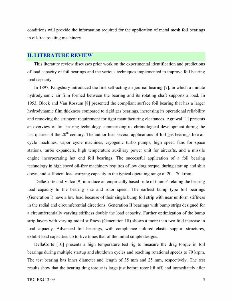
II. LITERATURE REVIEW This literature review discusses prior work on the experimental identification and predictions
of load capacity of foil bearings and the various techniques implemented to improve foil bearing
load capacity.
In 1897, Kingsbury introduced the first self-acting air journal bearing [7], in which a minute
hydrodynamic air film formed between the bearing and its rotating shaft supports a load. In
1953, Block and Van Rossum [8] presented the compliant surface foil bearing that has a larger
hydrodynamic film thickness compared to rigid gas bearings, increasing its operational reliability
and removing the stringent requirement for tight manufacturing clearances. Agrawal [1] presents
an overview of foil bearing technology summarizing its chronological development during the
last quarter of the 20th century. The author lists several applications of foil gas bearings like air
cycle machines, vapor cycle machines, cryogenic turbo pumps, high speed fans for space
stations, turbo expanders, high temperature auxiliary power unit for aircrafts, and a missile
engine incorporating hot end foil bearings. The successful application of a foil bearing
technology in high speed oil-free machinery requires of low drag torque, during start up and shut
down, and sufficient load carrying capacity in the typical operating range of 20 – 70 krpm. DellaCorte and Valco [9] introduce an empirically based ‘rule of thumb’ relating the bearing
load capacity to the bearing size and rotor speed. The earliest bump type foil bearings
(Generation I) have a low load because of their single bump foil strip with near uniform stiffness
in the radial and circumferential directions. Generation II bearings with bump strips designed for
a circumferentially varying stiffness double the load capacity. Further optimization of the bump
strip layers with varying radial stiffness (Generation III) shows a more than two fold increase in
load capacity. Advanced foil bearings, with compliance tailored elastic support structures,
exhibit load capacities up to five times that of the initial simple designs.
DellaCorte [10] presents a high temperature test rig to measure the drag torque in foil
bearings during multiple startup and shutdown cycles and reaching rotational speeds to 70 krpm.
The test bearing has inner diameter and length of 35 mm and 25 mm, respectively. The test
results show that the bearing drag torque is large just before rotor lift off, and immediately after

TRC-B&C-3-09 6
rotor touchdown, due to rubbing contact between the journal and the top foil surface. Once the
bearing is airborne, the drag torque reduces to a minimum, and then increases gradually with
rotor speed. In further tests in Ref. [11], the foil bearing torque increases with static load and
decreases with operating temperature. The frictional force and contact stress between the top foil
and the shaft surface contributes to the large drag torque at start up. The load capacity is
estimated by coasting down the rotor from a high speed, while a static load is applied on the foil
bearing, until the drag torque suddenly rises indicating the onset of rubbing. In a gas bearing, the
load capacity approaches a limit, not increasing further with surface speed. The experimental
load capacity in the test bearing is linear with speed to 30 krpm. It is speculated that a foil
bearing reaches its ultimate load capacity when the minimum film thickness approaches the
combined surface roughness of the top foil and the rotating shaft [11]. In the tests, the foil
bearing load capacity decreases with increasing operating temperature, possibly due to the
decrease in the support structure stiffness. Note that the ultimate load capacity of a foil bearing
cannot exceed that of its resilient support structure, i.e. the bump strip layers.
Radil et al. [12] reports that the load capacity of a Generation III foil bearing, with inner
diameter of 35 mm and length 25 mm and constructed from several nickel based super alloy
foils, is the highest for a near optimum clearance. Note that clearance in a foil bearing is a vague
concept since in actuality, upon assembly, no physical gap exists between a top foil and a
stationary shaft. Continuous operation of a foil bearing that has a suboptimal clearance results in
thermal runaway failure and seizure. However, a foil bearing can be operated safely with a radial
clearance larger than the optimal value, but at a reduced load capacity. Ref. [13] shows that
tailoring the support structure, to reduce the side leakage and to provide a uniform film
thickness, results in a higher load capacity.
Peng and Khonsari [14] determine the ultimate load capacity of ideal foil bearings, showing
its dependency on the stiffness (compliance) of the support structure beneath the top foil. Kim
and San Andŕes [15] further advance the analysis to determine the effect of assembly preload on
the ultimate load capacity for gas foil bearing operation at ultra high operating speeds. Note that
foil bearings are typically assembled with a slight preload, i.e., the inner diameter of the top foil
bring smaller than the journal diameter.
The current research does not focus on the tribological characteristics [16, 17] of solid
lubricant coatings on the top foil and the rotating shaft.

TRC-B&C-3-09 7
III. DESCRIPTION OF TEST BEARING AND EXPERIMENTAL FACILITY TEST METAL MESH FOIL BEARING
Figure 6 shows the photograph of a prototype bearing and Table 1 describes the three main
components comprising a MMFB. The MMFBs employ commercially available ring shaped
metal mesh as the elastic support under a thin top foil. The prototype bearing uses a metal mesh
ring made of copper wires, owing to the large structural damping offered by copper meshes [3].
The top foil, a smooth arcuate surface 127µm thick, is in contact with the journal when not in
operation. Note that, at high rotor speed operation, a thin hydrodynamic air film separates the top
foil and the rotating journal. Hence, any wear of the journal or the bearing is absent while the
rotor is airborne. In MMFBs, the metal mesh supporting the top foil also provides material
damping and dry-friction energy dissipation effects [3].
Fig. 6 Photograph of a metal mesh foil bearing manufactured at TAMU
The top foil is made from a cold rolled steel strip (Chrome-Nickel alloy, Rockwell 40/45)
with significant resilience to deformation. The steel strip is first heat treated in a die at a
temperature of 927° C and then allowed to cool for ~ 10 hours. Further, a tempering process at ~
400 ° C toughens the formed top foil. The heat treatment process follows the recommendations
in Ref. [14] that details the heat treatment processes typically employed in the manufacturing of
top foils in commercial bearings.
Metal mesh ring
Top Foil
Bearing cartridge

TRC-B&C-3-09 8
Table 1. Description of metal mesh foil bearing components
Description Role
Bearing Cartridge Stainless steel cylindrical ring Cartridge holding metal mesh ring and smooth top foil.
Metal mesh ring (MM)
Ring shaped compressed woven wire mesh
Soft material support provides structural stiffness and energy dissipation
Smooth top Foil
Thin Stainless steel sheet,curved and preformed, with oneend affixed to the metal meshring and the other end free.
A hydrodynamic film pressure builds up within the gap between the rotating shaft and the top foil.
Figure 7 displays a schematic representation of a cross sectional view of the test MMFB and
illustrates the installation of the smooth arcuate top foil inside the metal mesh ring. One end of
the top foil has two identical shaped tabs that are bent and fit into the two apertures inside the
ring shaped metal mesh during assembly. After affixing the top foil into the metal mesh, the
assembly is inserted into the bearing cartridge to complete the construction of the MMFB [6]. A
thin and uniform solid lubricant coating of MoS2 is applied on the top foil inner surface to
protect it from excessive wear due to frictional contact with the rotating journal. Table 2 displays
the dimensions of the MMFB with the metal mesh ring inner diameter of 28.30 mm and axial
length of 28.05 mm. Cooper wire with a diameter of 0.30 mm comprises of a metal mesh ring
with a compactness of 20%. The compactness (wire density) of the metal mesh determines its
physical (equivalent) properties [3]. Stainless steel top foil thickness is 0.127 mm. The total mass
of MMFB including a torque arm (see Fig. 8) is ~ 0.363 kg.

TRC-B&C-3-09 9
Fig. 7 Schematic representation of cut view of the MMFB
Table 2. Nominal dimensions and material specifications for test MMFB
Parameter name and physical dimension Magnitude
Bearing cartridge outer diameter, DBo (mm) 58.15 ± 0.02
Bearing cartridge inner diameter, DBi (mm) 42.10 ± 0.02
Bearing axial length, L (mm) 28.05 ± 0.02
Metal mesh outer diameter, DMMo (mm) 42.10 ± 0.02
Metal mesh inner diameter, DMMi (mm) 28.30 ± 0.02
Metal mesh mass, Mm (kg) 0.0391
Metal mesh density, ρMM (%)1 20
Top foil thickness, Ttf (mm) 0.127
Wire diameter, DW (mm) 0.30
Copper Young modulus, E (GPa), at 21 ºC [18] 114
Copper Poisson ratio, υ [19] 0.33
Bearing mass (cartridge + mesh + foil + torque arm), M (kg)
0.363
Uncertainty in mass measurement = ±0.0001 kg
1 Manufacturers define the density of metal mesh as the ratio of the ring mass to its volume times the metal material density.
Metal Mesh Ring
DMMi DBi DBo
Top Foil
Tabs
L
Bearing Cartridge

TRC-B&C-3-09 10
EXPERIMENTAL FACILITY Figure 8 shows a photograph of the test rig with a ball bearing supported turbocharger (TC)
turbine driving the system to a maximum speed of 120 krpm. The compressor impeller and
volute of the original TC are removed to expose the overhanging shaft. A journal of diameter 28
mm and length 55 mm is press fitted on the TC shaft end and fastened with a nut. The journal is
balanced in-place using correction masses inserted at eight equally spaced threaded holes on the
journal front face. The MMFB slides on the journal and remains afloat when the journal starts
rotating. A torque arm attached to the bearing prevents its rotation.
Fig. 8 Photograph of test rig with metal mesh foil bearing mounted on journal (28 mm diameter and 55 mm length
Figure 9 shows a schematic front view of the test bearing, journal, and the devices for
measurement of torque, applied load and temperature. Once the journal starts rotating, the torque
arm applies a force on the soft spring (0.88 kN/m), and the spring reaction force balances the
drag moment acting on the bearing. An eddy current sensor records the lateral displacement of
the torque arm. The rubber band shown gives a slight preload and prevents axial motions of the
test bearing.
Static (horizontal) loads are applied on the bearing by pulling a string (flexible) connected to
the bearing, using a positioning table. A dynamometer (± 0.2 N) affixed to the linear positioning
table measures the applied load. As the positioning table moves toward left, as illustrated in
Test MMFB
Journal
Thermocouple
Oil outlet
Turbocharger Oil inlet
Torque arm String for pulling static load

TRC-B&C-3-09 11
Figure 9, the string applies a horizontal load on the bearing floating on the shaft. Note that the
string, loosely wound around the bearing circumference (at its axial mid-plane) does not prevent
the bearing rotation, thus facilitating seamless torque measurement. Incidentally, note that the
weight of the bearing assembly is 3.5 N. A K-type thermocouple affixed at one of the bearing
ends measures the top foil temperature (± 0.5 °C). An infrared tachometer, mounted within the
safety structure, measures the turbine tip speed with ± 0.0015 % accuracy.
Fig. 9 Schematic view of MMFB, rotating journal, and instrumentation for static (pull) load and torque measurements
A pressure regulator adjusts the supply air pressure [8.1 bar (120 psig) max.] into the turbine
inlet. A ball valve throttles the inlet air and the exhaust air is routed from the test cell to the
outside environment. The gradual increase of the inlet air into the turbine accelerates the rotor to
a certain steady state speed. Further, depending on the test type, either the inlet air is suddenly
cut or gradually reduced (stepwise), the rotor speed decreases until it stops rotating.
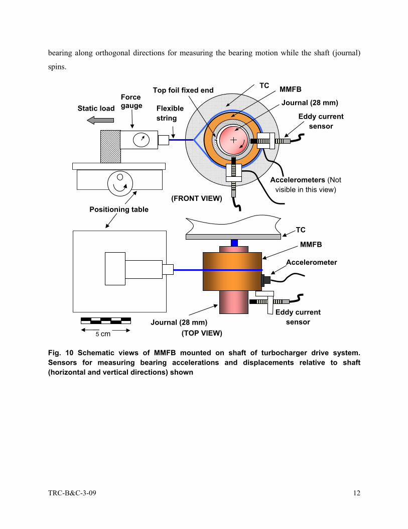
The torque arm is later removed and two eddy current sensors and two miniature
piezoelectric accelerometers (each weighing 5.1 g), as shown in Figure 10, are affixed to the test
Thermocouple
Positioning table Torque arm
Calibrated spring
MMFB
Shaft String to pull bearing Static load
Eddy current sensor
Force gauge
Top foil fixed end
Preloading using a rubber
band
5 cm
TRC-B&C-3-09 12
bearing along orthogonal directions for measuring the bearing motion while the shaft (journal)
spins.
Fig. 10 Schematic views of MMFB mounted on shaft of turbocharger drive system. Sensors for measuring bearing accelerations and displacements relative to shaft (horizontal and vertical directions) shown
Positioning table
MMFB
Journal (28 mm) Flexible string
Static load Force gauge
Top foil fixed end
5 cm (TOP VIEW)
Accelerometer
Eddy current sensor
Eddy current sensor
MMFB
Journal (28 mm)
TC
TC
Accelerometers (Not visible in this view)
(FRONT VIEW)

TRC-B&C-3-09 13
IV. MEASUREMENT OF DRAG TORQUE, LIFT-OFF SPEED, AND TOP FOIL TEMPERATURE IN A METAL MESH FOIL BEARING
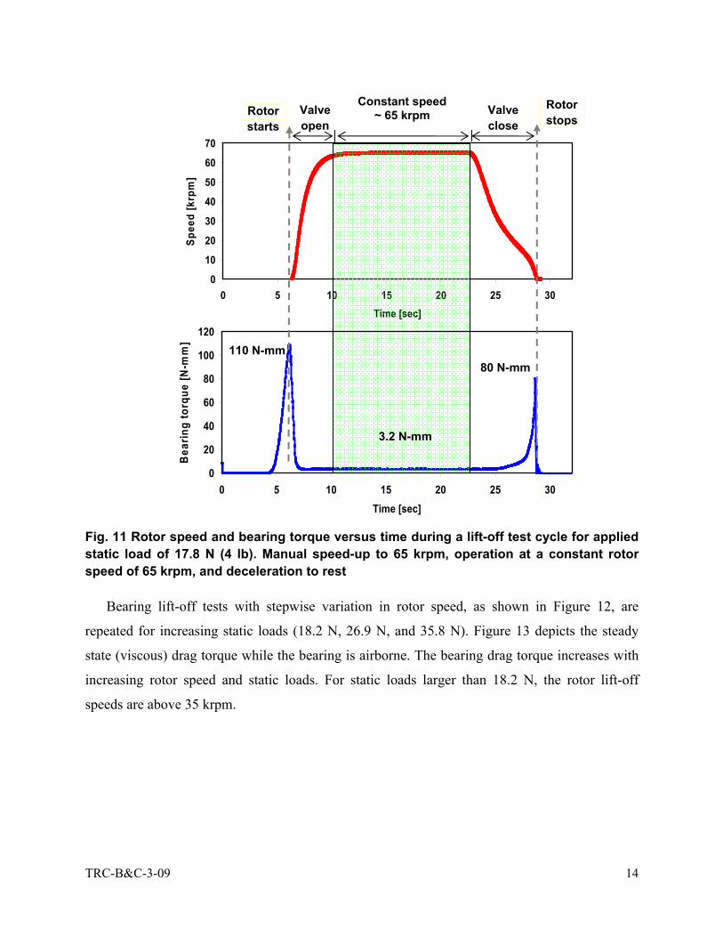
MEASUREMENT OF BEARING DRAG TORQUE The air inlet valve is controlled to accelerate the TC shaft from rest, maintain it at a steady
speed, and then decelerate it to rest as the air valve is closed. Figure 11 shows the journal speed
and bearing drag torque versus time during a lift-off test cycle with an applied static (pull) load
of 17.8 N (4 lb). The rotor accelerates beyond the bearing lift of speed (~ 28 krpm) to a steady
speed of 65 kprm, and then decelerated to rest. As the rotor starts to spin, rubbing between the
journal and top foil surfaces generate a sharp peak in bearing torque (~ 110 N-mm). Once the
journal starts rotating, the torque falls rapidly. Further, the bearing operates in a mixed
lubrication regime with partial asperity contacts, until the thin air film completely separates the
two surfaces. The airborne journal, at a steady speed of 65 kprm, offers a significantly smaller
drag torque of ~ 3.2 N-mm, i.e. 3% of the peak (break-up) torque. While decelerating to rest, the
journal comes into physical contact with the top foil and causes a sharp peak in the drag torque
(80 N-mm).
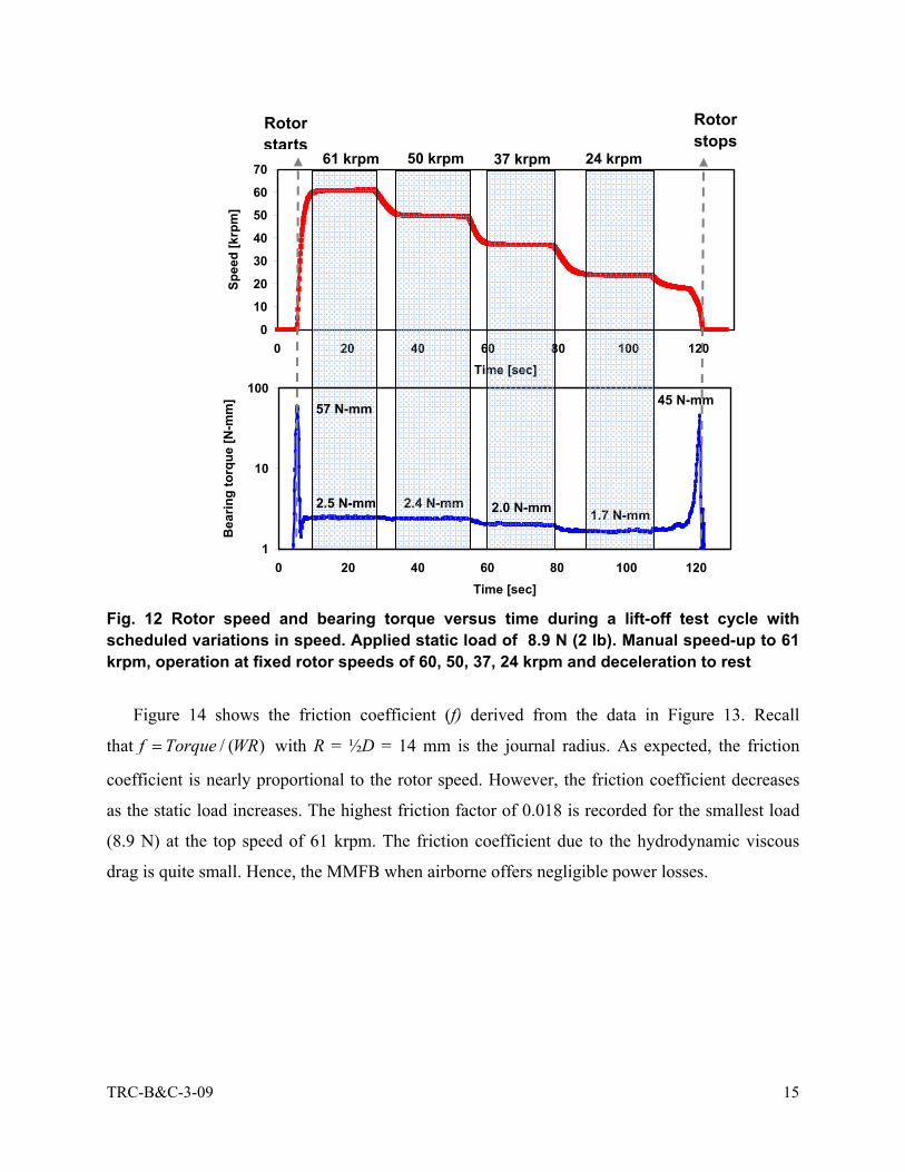
The lift-off shut-down test cycle is again conducted with a step wise change in the rotating
speed. Figure 12 shows the rotor speed and bearing drag torque versus time with an applied static
load of 8.9 N (2 lb). Note that the (horizontal) direction of the static pulling load (WS) is 90°
away from that of the bearing dead weight (WD=3.5 N). Hence, the total static load acting on the
MMFB is 2 2S DW = W +W 2.The opening of the valve instantly brings the rotor to 65 krpm,
overcoming a dry friction torque, due to rubbing with the top foil, of 57 N-mm. Once airborne,
the viscous drag torque, between the air film and the top foil, is only 2.5 N-mm. Next, after every
20 s, the air inlet valve to the turbine is closed a little more, to reduce the rotor speed in a
stepwise manner. The drag torque decreases with journal speed, to 2.4 N-mm at 50 krpm, to 2.0
N-mm at 37 krpm, to 1.7 N-mm at 24 krpm, respectively. Further reduction in the rotor speed
evidences an increase in drag torque. The drag torque peaks to 45 N-mm just before the rotor
comes to rest.
2 Total static load is 9.6 N, 18.2 N, 26.9 N, and 35.8 N for the applied (horizontal) static loads of 8.9 N, 17.8 N, 26.7 N, and
35.6 N, respectively.
TRC-B&C-3-09 14
Fig. 11 Rotor speed and bearing torque versus time during a lift-off test cycle for applied static load of 17.8 N (4 lb). Manual speed-up to 65 krpm, operation at a constant rotor speed of 65 krpm, and deceleration to rest
Bearing lift-off tests with stepwise variation in rotor speed, as shown in Figure 12, are
repeated for increasing static loads (18.2 N, 26.9 N, and 35.8 N). Figure 13 depicts the steady
state (viscous) drag torque while the bearing is airborne. The bearing drag torque increases with
increasing rotor speed and static loads. For static loads larger than 18.2 N, the rotor lift-off
speeds are above 35 krpm.
0
20
40
60
80
100
120
0 5 10 15 20 25 30Time [sec]
Bea
ring
torq
ue [N
-mm
]
0
10
20
30
40
50
60
70
0 5 10 15 20 25 30Time [sec]
Spee
d [k
rpm
]
Rotor starts
Rotor stops
Constant speed ~ 65 krpm
80 N-mm
Valve open
Valve close
3.2 N-mm
110 N-mm
TRC-B&C-3-09 15
Fig. 12 Rotor speed and bearing torque versus time during a lift-off test cycle with scheduled variations in speed. Applied static load of 8.9 N (2 lb). Manual speed-up to 61 krpm, operation at fixed rotor speeds of 60, 50, 37, 24 krpm and deceleration to rest
Figure 14 shows the friction coefficient (f) derived from the data in Figure 13. Recall
that / ( )f Torque WR= with R = ½D = 14 mm is the journal radius. As expected, the friction
coefficient is nearly proportional to the rotor speed. However, the friction coefficient decreases
as the static load increases. The highest friction factor of 0.018 is recorded for the smallest load
(8.9 N) at the top speed of 61 krpm. The friction coefficient due to the hydrodynamic viscous
drag is quite small. Hence, the MMFB when airborne offers negligible power losses.
1
10
100
0 20 40 60 80 100 120Time [sec]
Bea
ring
torq
ue [N
-mm
]
0
10
20
30
40
50
60
70
0 20 40 60 80 100 120Time [sec]
Spee
d [k
rpm
]
Rotor starts
Rotor stops
61 krpm 50 krpm 37 krpm 24 krpm
2.5 N-mm
57 N-mm 45 N-mm
2.4 N-mm 2.0 N-mm 1.7 N-mm

TRC-B&C-3-09 16
Fig. 13 Bearing viscous drag torque versus rotor speed for increasing static loads. MMFB airborne
Fig. 14 MMFB friction coefficient f versus rotor speed for increasing static loads. Steady state operation with bearing airborne
Figure 15 displays the bearing break away torque versus static load measured during (four)
rotor speed-up tests to ~ 60 krpm. The largest dry friction induced torque is observed when the
rotor begins to spin. After the series of rotor liftoff tests, a post-inspection of the top foil surface
showed its protective MoS2 layer had disappeared. The top foil surface is sprayed again with the
0
0.5
1
1.5
2
2.5
3
3.5
4
4.5
20 30 40 50 60 70 80Rotor speed [krpm]
Bea
ring
torq
ue [N
-mm
]8.9 N (2 lb)
17.8 N (4 lb)
26.7 N (6 lb)
35.6 N (8 lb)
Rotor not lifted off
Dead weight (WD= 3.6 N)
Increasing static load (Ws) to 35.6 N (8 lb)
0
0.005
0.01
0.015
0.02
0.025
20 30 40 50 60 70 80Rotor speed [krpm]
Fric
tion
coef
ficie
nt [-
] 8.9 N (2 lb)
17.8 N (4 lb)
26.7 N (6 lb)
35.6 N (8 lb)

TRC-B&C-3-09 17
solid lubricant, and the bearing break away torque measured while rotating the journal manually.
Figure 15, showing these measurements, clearly depicts that the recoated top foil surface reduces
the drag torque, for instance by ~30 % for the highest static load of 35.8 N.
Fig. 15 MMFB break away torque versus static load. Measurements from rotor speed start up tests to 60 krpm and post-test with (fresh) MoS2 layer deposited on top foil
Figure 16 depicts the bearing friction coefficient / ( )f Torque WR= estimated from the
measurements shown in Figure 15. This friction coefficient represents the rubbing contact (dry
frictional sliding) between the rotor and the top foil surface. The estimated value of f decreases
from ~0.4 to ~ 0.37, with an increase in the static load from 9.6 N to 35.8 N, for the top foil with
a worn layer of MoS2. These friction coefficient magnitudes are typical for metal to metal
contact. After spraying the top foil with a new sacrificial layer of MoS2, the dry friction
coefficient ranges from ~0.3 to 0.2 as the static load increases from 9.6 N to 35.8 N. The
experimental results imply the need of adequate and enduring solid lubricants to reduce MMFB
drag torque during the rotor start up (and shut down.
0
20
40
60
80
100
120
140
160
180
0 10 20 30 40Static load [N]
Stal
l tor
que
[N-m
m] Worn MoS2
layer Fresh coating
of MoS2

TRC-B&C-3-09 18
Fig. 16 Dry-friction coefficient of MMFB versus static loads. Measurements from rotor speed start up tests to 60 krpm and post-test with (fresh) MoS2 layer deposited on top foil
Figure 17 shows the bearing drag torque versus rotor speed, during rotor speedup, for
increasing static loads of 9.6 N, 18.2 N, 26.9 N and 35.8 N. Note that the uncertainty in drag
torque is ± 0.35N-mm for drag torque < 10 N-mm. For each static load, as the rotor speed
increases, initially the bearing drag torque decreases quickly and, when the journal is airborne,
increases gradually with rotor speed. The lowest drag torque provides the rotor lift off speed.
Note that for operation at 60 krpm, the measured drag torque is nearly identical to those recorded
under steady journal speed, see Figure 13. Figure 18 show that the friction coefficient f changes
only slightly with rotor speed after the rotor is airborne, i.e. once the MMFB operates with a
hydrodynamic film. The identified f is the lowest for the largest applied load of 35.8 N.
Owing to the very low friction coefficient, f ~0.01 to 0.02 (when the bearing is airborne), the
drag power losses in the bearing are rather small. For example, at 60 krpm and the highest static
load, the estimated power loss, P=Torque x Ω ~ 4 N-mm x 60000 (π/30) = 25.1 W.
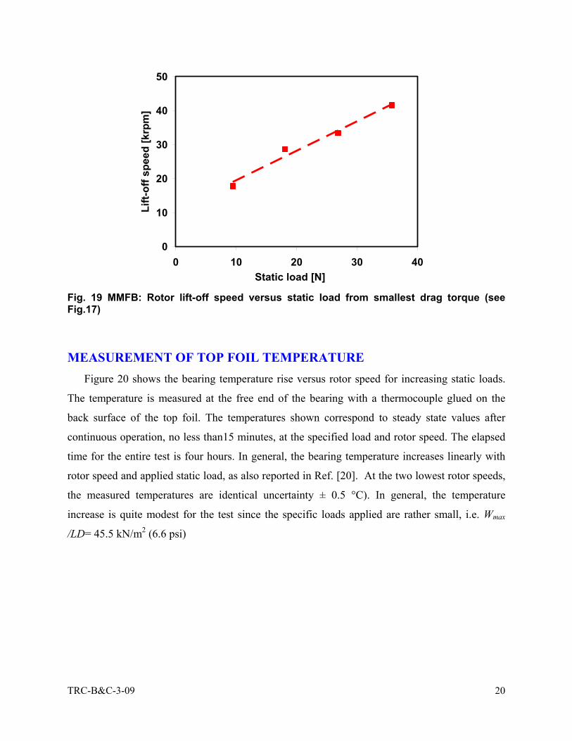
The rotor lift-off speed, as shown in Figure 19, is proportional to the static load imposed on
the bearing. Once the shaft starts spinning, the bearing drag torque rises to a peak; then at a
certain threshold speed when the bearing is airborne, the torque suddenly drops and remains at
this small magnitude as long as there is an air film. The rotational speed beyond which the
bearing operates with a significantly smaller drag torque, in comparison to the large startup
0
0.1
0.2
0.3
0.4
0.5
0 10 20 30 40Static load [N]
Fric
tion
coef
ficie
nt [-
]
Worn MoS2 layer
Fresh MoS2 layer
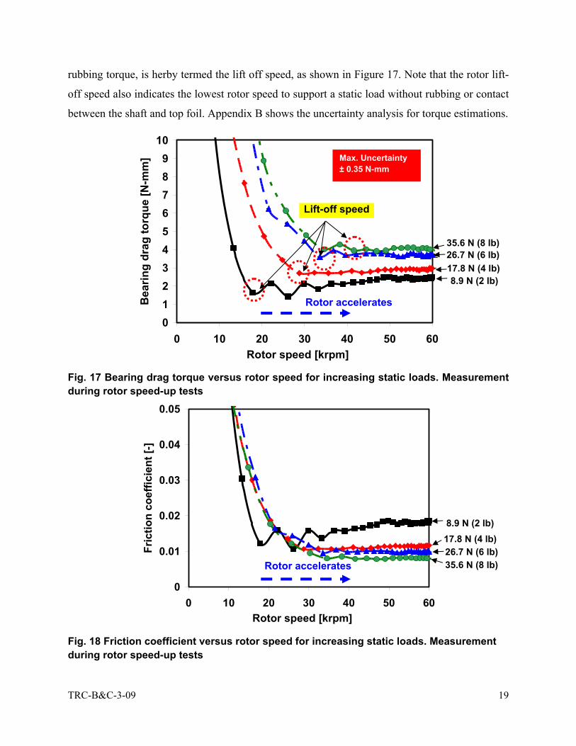
TRC-B&C-3-09 19
rubbing torque, is herby termed the lift off speed, as shown in Figure 17. Note that the rotor lift-
off speed also indicates the lowest rotor speed to support a static load without rubbing or contact
between the shaft and top foil. Appendix B shows the uncertainty analysis for torque estimations.
Fig. 17 Bearing drag torque versus rotor speed for increasing static loads. Measurement during rotor speed-up tests
Fig. 18 Friction coefficient versus rotor speed for increasing static loads. Measurement during rotor speed-up tests
0
0.01
0.02
0.03
0.04
0.05
0 10 20 30 40 50 60Rotor speed [krpm]
Fric
tion
coef
ficie
nt [-
]
Rotor accelerates
8.9 N (2 lb)17.8 N (4 lb)26.7 N (6 lb)35.6 N (8 lb)
0123456789
10
0 10 20 30 40 50 60Rotor speed [krpm]
Bea
ring
drag
torq
ue [N
-mm
]
Lift-off speed
Rotor accelerates
8.9 N (2 lb)17.8 N (4 lb)26.7 N (6 lb)35.6 N (8 lb)
Max. Uncertainty ± 0.35 N-mm
TRC-B&C-3-09 20
Fig. 19 MMFB: Rotor lift-off speed versus static load from smallest drag torque (see Fig.17)
MEASUREMENT OF TOP FOIL TEMPERATURE Figure 20 shows the bearing temperature rise versus rotor speed for increasing static loads.
The temperature is measured at the free end of the bearing with a thermocouple glued on the
back surface of the top foil. The temperatures shown correspond to steady state values after
continuous operation, no less than15 minutes, at the specified load and rotor speed. The elapsed
time for the entire test is four hours. In general, the bearing temperature increases linearly with
rotor speed and applied static load, as also reported in Ref. [20]. At the two lowest rotor speeds,
the measured temperatures are identical uncertainty ± 0.5 °C). In general, the temperature
increase is quite modest for the test since the specific loads applied are rather small, i.e. Wmax
/LD= 45.5 kN/m2 (6.6 psi)
0
10
20
30
40
50
0 10 20 30 40Static load [N]
Lift-
off s
peed
[krp
m]

TRC-B&C-3-09 21
Fig. 20 Bearing temperature rise versus rotor speed for airborne operation with increasing static loads. Estimation at steady state rotor speeds (after 15 min. for each condition). Ambient temperature at 21 °C
V. CONCLUSIONS Metal mesh foil bearings (MMFBs) offer promise as a reliable support in oil-free high speed
rotating machinery. MMFBs provide a tunable resilient support with large (material) damping.
Most importantly, the MMFB configuration is simple and of little cost since it uses commercially
available materials. Note that metal mesh ring structural properties can be changed by modifying
its geometrical dimensions and compactness, thus promoting the scalability of this bearing
technology.
The report presents the measurement of drag torque, rotor lift-off speed, and operating
temperature of a test MMFB mounted on a turbocharger air turbine driven test rig. The
measurements aim to characterize the static load performance of the MMFB over broad ranges of
rotor speed and static loads. The measurements show that the bearing break-away torque during
rotor speed start-up increases with increasing static loads. This dry-friction torque, typical of
metal to metal contact, is reduced by application of a sacrificial layer of MoS2. During rotor
airborne (hydrodynamic) operation, the bearing drag torque increases with the static load and
rotor speed. However, the friction coefficient is rather small (< 0.010) denoting negligible
02468
101214161820
20 30 40 50 60 70 80Rotor speed [krpm]
Tem
pera
ture
rise
[°C
]8.9 N (2 lb)
17.8 N (4 lb)26.7 N (6 lb)35.6 N (8 lb)

TRC-B&C-3-09 22
power losses. The rotor lift-off speed, estimated at the lowest drag torque, increases linearly with
static load. The test bearing steady state temperature is proportional to rotor speed and increases
with the applied static load. The experimental results provide a comprehensive database on
the static load performance of the simple and low cost prototype MMFB for increasing rotor
speed and temperature. The measurements demonstrate the reliable performance of a MMFB for
an oil-free application and pave the way for further developments.
MMFB structural stiffness and damping coefficients are identified, for the range of
frequencies 0-125 Hz, from impact load tests (See Appendix C). In these tests, the shaft does not
spin and the only load is due to the bearing weight. The bearing response shows a system with
large damping. The identified structural static stiffness is ~0.1 MN/m. The frequency dependent
stiffness gradually increases with frequency. The equivalent viscous damping coefficient
decreases from ~400 Ns/m to ~200 Ns/m as the frequency increases from 10 to 125 Hz. Further
experiments to determine the bearing force coefficients while the shaft rotates are planned.
CIATEQ A.C., a TRC member, donated two aluminum foam bearings; their viability for use
in high speed turbomachinery is not recommended due to their large stiffness and delicate
integrity of the metal foam.
REFERENCES [1] Agrawal, G., 1997, “Foil Air/Gas Bearing Technology – an Overview,” ASME Paper No.
97-GT-347.
[2] Valco, M.J., and DellaCorte, C., 2002, “Emerging Oil-Free Turbomachinery Technology for
Military Propulsion and Power Applications,” Proc. Of 23rd U.S. Army Science Conf. Ft.
Lauderdale, FL, Dec. 2-5.
[3] Al-Khateeb, E. M., 2002, “Design, Modeling and Experimental Investigation of Wire Mesh
Vibration Dampers,” PhD. Thesis, Texas A&M Univ. College Station, TX.
[4] Lee, Y. B., Kim, C. H., Jo, J. H., and Ryu, K., 2006, “Air Foil Bearing Having a Porous
Foil,” International Patent No. WO 2006/043736 A1.
[5] Zarzour, M. and Vance, J., 2000, “Experimental Evaluation of a Metal Mesh Bearing
Damper,” ASME J. Eng. Gas Turbines Power, 122(2), pp. 326-329.
[6] San Andrés, L., Kim, T. H., Chirathadam, T. A., and Martinez, A., 2008, “Measurement of
Structural Stiffness and Damping in a Metal Mesh Foil Bearing and Development of a Test

TRC-B&C-3-09 23
Rig for Gas Foil Bearings,” Technical Report TRC-B&C-5-08, Texas A&M Univ., College
Station, TX.
[7] Pinkus, O., 1987, “The Reynolds Centennial: A Brief History of the Theory of Lubrication,”
ASME J. Trib., 109, pp. 1-20.
[8] Blok, H. and van Rossum, J. J., 1953, “The Foil Bearing – A New Departure in
Hydrodynamic Lubrication,” Lub. Eng., 9(6), pp. 316-320
[9] DellaCorte, C., and Valco, M.J., 2000, “Load Capacity Estimation of Foil Air Journal
Bearings for Oil-Free Turbomachinery Applications,” NASA/TM-2000-209782.
[10] DellaCorte, C., 1997, “A New Foil Air Bearing Test Rig for use to 700° C and 70,000 rpm,”
NASA/TM-107405.
[11] DellaCorte, C., Lukaszewics, V., Valco, M.J., Radil, K.C., and Heshmat, H., 2000,
“Performance and Durability of High Temperature Foil Air Bearings for Oil-Free
Turbomachinery,” NASA/TM-2000-209187/REV1.
[12] Radil, K., Howard, S., and Dykas, B., 2002, “The Role of Radial Clearance on the
Performance of Foil Air Bearings,” NASA/TM-2002-211705.
[13] DellaCorte, C., Radil, K. C., Bruckner, R. J., and Howard, S. A., 2008, “ Design,
Fabrication, and Performance of Open Source Generation I and II Compliant Hydrodynamic
Gas Foil Bearings,” Tribol. Transactions, 51, pp. 254-264.
[14] Peng, Z.-C., and Khonsari, M. M., 2004, “On the Limiting Load-Carrying Capacity of Foil
Bearings,” ASME J. Tribol., 126, pp. 817-818.
[15] Kim, T.H., and L. San Andrés, 2006, “Limits for High Speed Operation of Gas
Foil Bearings,” ASME J. Tribol., 128, pp. 670-673.
[16] DellaCorte, C., Zaldana, A., and Radil, K., 2003, “A System Approach to the Solid
Lubrication of Foil Air Bearing for Oil-Free Turbomachinery,” ASME J. Tribol., 126(1), pp.
200-207.
[17] Jahanmir, S., Heshmat, H., and Heshmat, C., 2009, “Evaluation of DLC Coatings for High-
Temperature Foil Bearing Applications,” ASME J. Tribology, 131, pp. 011301-(1-11).
[18] Dodge, H.L., 1913, “The Physical Review,” American Institute of Physics, pp. 439.
[19] Boyd, J. E., 1917, Strength of Materials, McGraw-Hill Book Company, New York, pp.
[20] San Andrés, L., Kim, T.H., Ryu, K., Chirathadam, T. A.,Jarrett, C., Hagen, K., Martinez, A.,
Rice, B., Niedbalski, N., Hung, W., and Johnson, M., “Gas Bearing Technology for Oil-Free

TRC-B&C-3-09 24
Microturbomachinery – Research Experience for Undergraduate (REU) Program at Texas
A&M University,” ASME Paper No. GT2009-59920

TRC-B&C-3-09 25
APPENDIX A. CALIBRATION OF EDDY CURRENT SENSOR AND SPRING CONSTANT
Figures A.1 and A.2 display the calibration curves for a mechanical spring (torque
measurement) and an eddy current sensor (Aluminum target). A dynamometer applies a force on
the steel spring and the eddy current sensor measures the corresponding deflection. The
estimated spring constant is 879.5 N/m. The gain of the eddy current sensor for the Aluminum
target, 13.446 V/mm, is estimated using the displacement reading from a positioning table digital
readout and the corresponding eddy current sensor voltage due to the aluminum target
displacement.
F [N] = 0.8795 [N/mm]* X [mm] + 0.0166R2 = 0.9987
0
0.5
1
1.5
2
2.5
3
3.5
0 1 2 3 4Displacement [mm]
Forc
e [N
]
Fig. A.1 Force versus displacement (Calibration of spring for torque measurement)

TRC-B&C-3-09 26
V [V] = 13.446 [V/mm]* X [mm] + 5.9012
R2 = 1
0
5
10
15
20
25
0 0.2 0.4 0.6 0.8 1Displacement [mm]
Out
put v
olta
ge [V
]
Fig. A.2 Calibration of Eddy Current Sensor (3300 XL) for Aluminum target

TRC-B&C-3-09 27
APPENDIX B. UNCERTAINTY ANALYSIS
EDDY CURRENT SENSOR CALIBRATION
The proximity sensor calibration uses displacement reading from a positioning table digital
readout (Ud = ± 0.0005 mm) and a voltmeter (Uv= ± 0.005 V). The eddy current proximity
sensor gain follows the relationship
fit
DGV
ΔΔ
= (B.1)
where ΔD is the change in displacement for a change in voltage, ΔVfit. , resulting from the linear
fit. The general equation for computing the uncertainty of parameters for a typical expression, r
= f(x1, x2, …xns), is defined as
1 2 n
2 2 2r x x x
1 1 n
r r rU ( U ) ( U ) ... ( U )x x x
∂ ∂ ∂= + + +
∂ ∂ ∂
(B.2)
The uncertainty of expression B.1, using equation B.2 becomes
fitVfit2 2 2 2 2G D D
fit fit
UUU U UG G 1 1( ) ( ) ( ) ( ) ( )G D D V G D VΔ Δ
∂ ∂= + = +
∂ ∂
(B.3)
where DΔ and fitVΔ are the range of experimental values and fitVU is computed from the
uncertainty of the voltmeter and the uncertainty of the curve fit as described
fit
2 2V fit VU (U ) (U )= + (B.4)
Hence, G =13.44 ± 0.007 V/mm
CALIBRATION OF SPRING CONSTANT
The spring3 constant calibration uses displacement reading from a positioning table digital
readout (Ud = ±0.0005 mm) and a force gauge (Uf = ± 0.2 N). The spring constant follows the
relationship
fit
FKD
ΔΔ
= (B.5)
3 For measurement of drag torque

TRC-B&C-3-09 28
The uncertainty of expression B.5, using equation B.2 becomes
fitDfit2 2 2 2 2K F F
fit fit
UUU U UK K 1 1( ) ( ) ( ) ( ) ( )K F F D K F DΔ Δ
∂ ∂= + = +
∂ ∂
(B.6)
Where FΔ and fitDΔ are the range of experimental values and fitDU is computed from the
uncertainty of the displacement measurement and the uncertainty of the curve fit as described
fit
2 2D fit DU (U ) (U )= + (B.7)
Thus, K = 0.88 ± 0.03 N/mm
TORQUE MEASUREMENT
The torque measurement follows the relationship
T V G K L= (B.8)
where, T is the bearing torque, V the voltmeter reading, G the Eddy current sensor
gain, K the spring constant, and L the torque arm length. The uncertainty of
expression B.8, using equation B.2 becomes
2 2 2 2 2V GT K LU UU U U( ) ( ) ( ) ( ) ( )T V G K L
= + + + (B.9)
The uncertainty in the measurement of torque of 10 Nmm is ± 0.35 Nmm using eqn. (B.9)

TRC-B&C-3-09 29
APPENDIX C. IDENTIFICATION OF MMFB STIFFNESS AND DAMPING COEFFICIENTS FROM IMPACT LOAD TESTS MODEL OF THE TEST BEARING
Figure C.1 shows a representation of the bearing force coefficients and the impact forces
exerted on the test bearing. Recall that the bearing floats atop the rotating shaft or journal, and it
rests on the journal while the journal is not rotating.
Fig. C.1 Representation of bearing force coefficients and impact forces acting on test bearing
The equations of motion of the test bearing modeled as a 2DOF mechanical system are
X X XX XY XX XY
Y Y YX YY YX YY
f M a C C K Kx xf M a C C K Ky y
δ δδ δ
−⎛ ⎞ ⎡ ⎤ ⎡ ⎤⎛ ⎞ ⎛ ⎞= +⎜ ⎟ ⎜ ⎟ ⎜ ⎟⎢ ⎥ ⎢ ⎥− ⎝ ⎠ ⎝ ⎠⎝ ⎠ ⎣ ⎦ ⎣ ⎦
(C.1)
where i i=X,Y f are the excitation forces, M=0.38 kg is the test system mass, ,i i X Y a = are the
accelerations of the bearing cartridge, and ij ij i j X Y K C =, , , are the bearing stiffness and damping
coefficients, respectively. Xδ and Yδ are the relative displacements of the bearing with respect
to the journal in the horizontal and vertical directions.
Only one of the equations above is needed to identify the stiffness and damping coefficients
when the journal does not spin. This is so since cross coupled coefficients are nil without journal
X
YKYY, CYY
KXY, CXY
Impact force, fY
Impact force, fX
Bearing Cartridge
Journal
KYX, CYX
KXX, CXX
Ω

TRC-B&C-3-09 30
rotation. Thus, the uncoupled equation of motion along one direction (Y) represented in the
frequency domain is
[ ] [ ]YYY Y YY
F K M A Y i CY
ω= ++ * ( / ) (C.2)
where YF , YA and Y are the FFTs of the impact force, the bearing accelerations and the relative
bearing displacement along the vertical (y) direction. KXX = KYY and CXX = CYY are the identified
bearing stiffness and equivalent viscous damping coefficients, and ω is the excitation frequency.
TEST CONFIGURATION
Figure C.2 illustrates the schematic view of the test configuration for identifying the bearing
stiffness and damping coefficients along the vertical direction with impact load tests. An eddy
current sensor, at one end of the bearing cartridge, measures the bearing displacement with
respect to the journal. The model assumes that the whole bearing cartridge remains parallel to the
journal. A miniature accelerometer (5.1 g) records the accelerations of the bearing cartridge. Ten
impacts are provided in the vertical direction. Frequency domain averages are used to estimate
the bearing force coefficients.
Fig. C.2 Schematic view representing the impact loading of MMFB
Impact Hammer
Accelerometer
Ω
y
x
Eddy Current Sensor
MMFB
5 cm
MMFB floating on test journal
Turbocharger
journal

TRC-B&C-3-09 31
IMPACT TEST RESULTS Figure C.3 shows, for frequencies to 125 Hz, an excellent coherence (~ 1.00) for the
displacement due to 10 impact loads. The coherence between the signals is rather poor at higher
frequencies as the small impact force does not excite the high frequency bearing displacement
components. Figures C.4 and C.5 show the FFTs of the impact force and relative bearing
displacement with respect to the shaft, respectively. Note how the displacement amplitudes
decrease rapidly as the frequency increases, i.e. the test bearing appears to have large damping.
0
0.25
0.5
0.75
1
0 25 50 75 100 125Frequency [Hz]
Coh
eren
ce [-
]
Fig. C.3 Coherence between impact force and eddy current sensor signal. Average of 10 impacts. Journal not rotating
Figure C.6 depicts the FFT of the bearing cartridge acceleration (AY) and the derived
acceleration, from the relative displacement of the MMFB and the journal, i.e. |-ω2 Y| . The two
accelerations must coincide if the journal is not moving. Alas, this is not the case since the shaft
stub of the turbocharger is rather flexible. Hence, the cartridge acceleration must be kept, as
measured, in the model for identifying the stiffness and damping coefficients, see Eq. (C2).
Substituting AY = -ω2 Y is not correct.

TRC-B&C-3-09 32
Fig. C.4 FFT of the impact force along the vertical direction. Average of 10 impacts. Journal not rotating.
Fig. C.5 FFT of bearing Y-displacement with respect to the shaft due to the impact force along the vertical direction. Average of 10 impacts. Journal not rotating.
The bearing model, see Eqn. (C2), includes three unknowns, the bearing stiffness (KYY), the
equivalent viscous damping (CYY), and the bearing mass (M). Figure C.7 shows a curve fit of the
real part of Eqn. (C2) identifying the bearing static stiffness KYYo =0.118 N/μm and system mass
M=0.379 kg, which is nearly identical to the measured mass of 0.380 kg, The estimated test
Dis
plac
emen
t [um
]
Frequency [Hz] 0 25 50 75 100 125
0
1
2
3
Impa
ct fo
rce
[N]
Frequency [Hz] 0 25 50 75 100 125
0
0.1
0.2
0.3
0.4
0.5

TRC-B&C-3-09 33
system natural frequency is fn = (KYY/M)0.5 = 88.8 Hz, and the system critical damping
Ccrit=2*(KYYM)0.5 = 423 N.s/m
Fig. C.6 FFT of acceleration of bearing cartridge (measured and derived from displacement) versus frequency. Average of 10 impacts. Journal not rotating
Fig. C.7 (Force/displacement) versus (acceleration/displacement), and curve fit identifying the MMFB stiffness and mass coefficients. Average of 10 impacts. Journal not rotating
0 25 50 75 100 1250
0.2
0.4
0.6
0.8
1
Acceleration derived from relative displacement of bearing cartridge and shaft
Measured acceleration
Frequency [Hz]
Acc
eler
atio
n [m
/s2 ]
0 4 .105 8 .105 1.2 .106 1.6 .106 2 .1065 .105
3 .105
1 .105
1 .105
3 .105
5 .105
Re (F/Y) = Kest + Mest* Re (A/Y)
Kest = 1.179 * 105 N/m Mest = 0.379 kg
Curve fit
Re
(For
ce/ D
ispl
acem
ent)
Re (Acceleration/Displacement)

TRC-B&C-3-09 34
Figure C.8 shows the identified bearing stiffness KYY increasing with frequency. Figure C.9
depicts the estimated equivalent viscous damping CYY decreasing from ~ 400 Ns/m to ~200 Ns/m
as the frequency increases from 10 to 125 Hz. The damping ratio (CYY/ Ccrit ) decreases from ~
0.94 to 0.47. In general, the viscous damping in a metal mesh structure is inversely proportional
to the frequency and amplitude of motion. See Ref. [6] for further details.
Fig. C.8 Identified MMFB stiffness KYY versus frequency. Journal not rotating
Fig. C.9 Identified MMFB viscous damping CYY versus frequency. Journal not rotating
0 25 50 75 100 1250
0.1
0.2
0.3
0.4
0.5
Kest = 1.179 * 105 N/m
KYY = Re (F - MestAy)/Y
Frequency [Hz]
Stiff
ness
[MN
/m]
Eq. v
isco
us d
ampi
ng [N
s/m
]
Frequency [Hz]
CYY = Im est y(F - M A )/Yω
⎡ ⎤⎢ ⎥⎣ ⎦
0 25 50 75 100 1250
250
500
750
1000

TRC-B&C-3-09 35
APPENDIX D. ALUMINUM FOAM BEARINGS CIATEQ A.C, “Centro de Investigación y Asistencia Tecnologica de el Estado de Queretaro
(Mexico)” donated two aluminum foam bearings on 09-25-08. Figure D.1 shows a photograph
of the two bearings and Table D.1 lists their dimensions and specifications.
Fig. D.1 Aluminum Foam Bearings
Table D.1 Dimensions and specifications of Aluminum Foam Bearings
Parameters Bearing 1 Bearing 2
Bearing Cartridge Outer Diameter, Co [mm] 58.03 ± 0.01 58.02 ± 0.01
Bearing Cartridge Inner Diameter, Ci [mm] 42.11 ± 0.01 41.60 ± 0.01
Aluminum Foam inner Diameter, Fi [mm] [28.20, 29.30] 4 [28.04, 28.15]
Bearing Axial Length, L [mm] 28.07 ± 0.01 28.15 ± 0.01
Bearing Mass, M [kg] 0.1027 ± 0.00005 0.1017 ± 0.00005
Porosity % 865 93
Appearance of Foam Foam covers almost all the inner surface of the bearing cartridge
Foam covers only ~ 95% of the bearing inner surface
4 The aluminum foam inner diameter is not a constant along the circumferential direction owing to the rough surface finish. Table 1 shows a range of diameter values. 5 Porosity computed by considering an Aluminum density of 2.7 g/cc
Bearing 2 Bearing 1